Note: Descriptions are shown in the official language in which they were submitted.
CA 3176846
MULTI WELL TRAY FOR PERFORMING AUTOMATED REAGENT-BASED ASSAYS
FIELD
[0001]
The present disclosure relates to systems and apparatuses for performing
automated
reagent-based biochemical assays.
BACKGROUND INFORMATION
[0002] Automated molecular assay instrumentation offers numerous advantages,
however
most automated instruments suffer from a limited set of assay capabilities.
These limited
capabilities complicate or inhibit parallel processing of multiple assays and,
as a result, reduce
sample throughput and flexibility in assay choices. This is particularly true
for sensitive assays
such as those involving nucleic acid detection and/or an amplification
procedure. There are
many procedures in use for amplifying nucleic acids, including the polymerase
chain reaction
(PCR), (see, e.g., Mullis, "Process for Amplifying, Detecting, and/or Cloning
Nucleic Acid
Sequences," U.S. Pat. No. 4,683,195), transcription-mediated amplification
(TMA), (see, e.g.,
Kacian et al., "Nucleic Acid Sequence Amplification Methods," U.S. Pat. No.
5,399,491),
ligase chain reaction (LCR), (see, e.g., Birkenmeyer, "Amplification of Target
Nucleic Acids
Using Gap Filling Ligase Chain Reaction," U.S. Pat. No. 5,427,930), strand
displacement
amplification (SDA), (see, e.g., Walker, "Strand Displacement Amplification,"
U.S. Pat. No.
5,455,166), and loop-mediated isothermal amplification (see, e.g., Notomi et
al., "Process for
Synthesizing Nucleic Acid," U.S. Pat. No. 6,410,278). A review of several
amplification
procedures currently in use, including PCR and TMA, is provided in HELEN H.
LEE ET AL.,
NUCLEIC ACID AMPLIFICATION TECHNOLOGIES (1997).
[0003] Automated molecular assays incorporate the use of consumable
components, which
may or may not hold reagents utilized in the molecular assay to be performed,
which can be
manually loaded onto automated instrumentation. Providing such consumable
components that
are configured to limit contamination, enhance target detection, simplify
loading into and
transport within the system, enhance the operability of mechanical components
within the
1
Date recue/Date received 2023-04-06
automated system while lowering cost, and providing high performance in
connection with the
assay to be performed is desirable.
SUMMARY
[0004] The present disclosure relates to systems, methods, and apparatuses
for performing
automated reagent-based biochemical assays.
[0005] Accordingly, in an aspect of the present disclosure, there is
provided a single-piece
receptacle. The receptacle includes a body having a generally cylindrical
upper portion and a
tapered lower portion, the upper portion having an open end and the lower
portion being closed-
ended, an annular ring formed on an outer surface of the body, the annular
ring separating the
upper and lower portions of the body, a lip circumscribing the open end of the
upper portion, the
lip being adapted for inter-locking engagement with a mated cap, and a
plurality of longitudinally
oriented grooves formed in an inner surface of the upper portion of the body
and situated between
the open end and the annular ring. In various embodiments, the closed end of
the lower portion
may be flat or curved. The number of grooves disposed on the inner surface of
the upper portion
is selected from the group consisting of 2, 3, 4, 5, 6, 7, and 8. The lip may
radially-extend from
an exterior surface of the upper portion and tapers towards the open end
thereof.
[0006] In another aspect, the disclosure provides a cap securable to the
single-piece
receptacle. The cap includes a lower portion having an outer surface for
sealing engagement of
an inner surface of the open upper end of the body, the outer surface
including one or more
annular ring(s), an upper portion having a length, an inner surface, an outer
surface, and an open
end configured for engagement with an automated pipettor, and further
including one or more
recess(es), which can be concave in shape, disposed on the outer surface
thereof extending along
at least part of the length of the upper portion, and one or more linear
rib(s) disposed on the inner
surface of the upper portion, each linear rib having a length corresponding to
the length of at least
one of the recesses, and wherein each of the one or more linear ribs is
positioned on the inner
surface of the cap in a manner that corresponds to at least one of the
recesses such that at least
one linear rib lies on an inner surface of the cap that directly opposes the
position of at least one
recess on the outer surface of the cap, and a lip positioned between, and
extending radially away
from, the upper and lower portions, the lip including a plurality of locking
arms extending toward
2
Date Recue/Date Received 2022-09-26
the lower portion of the cap for securely engaging the lip of the receptacle.
In various
embodiments, the number of linear ribs corresponds to the number of recesses
in a one-to-one
relationship, and the number of recesses disposed on the outer surface of the
cap is selected from
the group consisting of 2, 3,4, 5, 6, 7, and 8. The lower portion of the cap
may include 1, 2, or 3
annular rings for sealing engagement of the inner surface of the body of the
receptacle.
100071 In certain embodiments, the locking arms comprise a snap fit
attachment for securely
engaging the lip of the receptacle. The number of locking arms may be selected
from the group
consisting of 1,2, 3,4, 5, 6, 7, and 8. In addition, the number of linear ribs
disposed on the inner
surface of the upper portion of the cap may be selected from the group
consisting of 2,3, 4,5, 6,
7, and 8. The distal portion of the cap may further include a bottom
separating the upper portion
of the cap from the proximal lower portion of the cap. In certain embodiments,
the bottom is
scored for piercing. The at least one of the linear rib includes a portion
that gradually tapers
radially inward toward the center of the upper portion, or increases in size
(e.g., an increase in
thickness or radial geometry) as the at least one of the linear ribs
approaches the bottom
separating the upper portion of the cap from the proximal lower of the cap.
[0008] In another aspect, the disclosure provides a method for the
automated removal of a cap
from a capped reaction receptacle. The method includes providing a single-
piece receptacle
comprising a body having a generally cylindrical upper portion and a tapered
lower portion, the
upper portion having an open end and the lower portion being closed-ended; an
annular ring
formed on an outer surface of the body, the annular ring separating the upper
and lower portions
of the body; a lip circumscribing the open end of the upper portion, the lip
being adapted for
inter-locking engagement with a mated cap; and a plurality of longitudinally
oriented grooves
formed in an inner surface of the upper portion of the body and situated
between the open end
and the annular ring; and a cap securable to the single-piece receptacle,
comprising: a lower
portion having an outer surface for sealing engagement of an inner surface of
the open upper end
of the body, the outer surface including one or more annular ring(s); an upper
portion having a
length, an inner surface, an outer surface, and an open end configured for
engagement with an
automated pipettor, and further including one or more recess(es) disposed on
the outer surface
thereof extending along at least part of the length of the upper portion, and
one or more linear
3
Date Recue/Date Received 2022-09-26
rib(s) disposed on the inner surface of the upper portion, each linear rib
having a length
corresponding to the length of at least one of the recesses, and wherein each
of the one or more
linear ribs is positioned on the inner surface of the cap in a manner that
corresponds to at least
one of the recesses such that at least one linear rib lies on an inner surface
of the cap that directly
opposes the position of at least one recess on the outer surface of the cap;
and a lip positioned
between, and extending radially away from, the upper and lower portions, the
lip including a
plurality of locking arms extending toward the lower portion of the cap for
securely engaging the
lip of the receptacle. The cap is securely engaged to the single piece
receptacle. The method
further includes performing an automated motion of contacting an inner portion
of at least one
of the plurality of locking arms with a raised annular ridge defined around a
receptacle slot,
wherein said contacting urges the locking arms away from the lip of the
receptacle thereby
disengaging the cap from the receptacle, and while the cap is disengaged from
the receptacle,
performing an automated motion of lifting the cap away from the receptacle,
thereby removing
the cap from the capped reaction receptacle.
[0009] In another aspect, the disclosure provides a multi-well tray for use
in an automated
process. The multi-well tray includes a base having a top surface, a card
insert having a first
surface, the card insert configured for removable attachment to the base,
wherein when attached
to the base, the first surface of the card insert is substantially parallel to
and flush with the top
surface of the base, and a plurality of sets of wells. Each set of wells
includes a first well disposed
in an opening of the top surface of the base, the first well being configured
to receive a receptacle
cap, second well disposed in an opening of the top surface of the base, the
second well being
configured to receive a receptacle, wherein the receptacle cap and the
receptacle are configured
for secure engagement with each other, and a third well disposed in an opening
of the first surface
of the card insert, the third well containing a lyophilized reagent. The wells
of each set of wells
are disposed in alignment with each other, and the third well is sealed with a
frangible seal. In
certain embodiments the third well may include one or more retention features
for retaining a
lyophilized reagent at the bottom thereof.
[0010] In another aspect, the disclosure provides a reagent-containing
multi-well tray for use
in an automated process. The multi-well tray includes a base having a top
surface and a plurality
4
Date Recue/Date Received 2022-09-26
of wells disposed therein. Each of the wells may be defined by a cylindrical
or conical wall, an
open upper end, and a bottom. The wells may be disposed in alignment with each
other and
sealed with a frangible seal. In certain embodiments each of the wells may
include at least one
retention feature to retain a lyophilized reagent therein. The multi-well tray
may further include
a lyophilized reagent disposed within each well, positioned at, or adjacent
to, the bottom.
Exemplary retention features include, but are not limited to, an annular ridge
formed on the well
wall and positioned above the lyophilized reagent, a spiral channel formed
along a length of the
well wall and positioned above the lyophilized reagent, a tapered ring
attached to the well wall
and positioned above the lyophilized reagent, a capillary insert attached to
the well wall, and a
collar attached to the well wall at or proximal to the open upper end. The
collar may further
include one or more fingers formed on a bottom surface thereof that protrude
along a radius of
curvature toward an axial center of the well. The capillary insert may include
an open upper end
that tapers toward the bottom of the well, and a capillary channel formed
between the open upper
end and the bottom of the well. In certain embodiments, the lyophilized
reagent is held in
position at, or adjacent to, the bottom through the use of electrostatic
force.
[00111 In
various aspects, any of the multi-well trays may also include machine readable
indicia positioned on the base or card insert containing identifying
information regarding the
multi-well tray or card insert, including reagents contained therein. The
machine readable indicia
may be a barcode, 2D barcode, or a radio frequency identification (RFID). In
addition, the multi-
well tray may include one or more locking arms disposed on the card insert for
locking
engagement with the base. The first well may be defined by a first side wall
and a bottom surface,
and include a protrusion extending from a center of the bottom surface of the
well toward the top
surface of the base for frictional engagement with a hollow portion in the
lower portion of the
receptacle cap. The first well may also include a plurality of tabs protruding
from the first side
wall for securely engaging the receptacle cap. The second well may be defined
by a second side
wall and a second bottom, the second bottom including a through-hole extending
from an inner
surface of the second well to an outer surface of the base. An annular ledge
may then be formed
within the second well at the circumference of the through-hole. The second
well may also
include a plurality of legs protruding from the second side wall for securely
engaging the distal
portion of the cap. The third well may be defined by a third side wall and a
third bottom and
Date Recue/Date Received 2022-09-26
include one or more features selected from the group consisting of a convex
groove, a concave
groove, and a set of grooves comprising a crisscross pattern disposed in the
third bottom. The
third side wall may be conical, tapering toward the bottom thereof. The third
well may also
include a plurality of rigid guides radially protruding from the third wall
toward a center thereof.
The base may be spatially indexed such that an automated pipettor can
accurately identify and/or
access any of the plurality of wells when the multi-well tray is placed in an
automated system.
[0012] In another aspect, the disclosure provides a cartridge with
communicating wells for
use in an automated process. The cartridge includes a casing having a top
surface, a fluid
chamber disposed within the casing, and wherein a first opening is provided in
the top surface of
the casing having at least one side wall surface extending to, or optionally
forming at least a
portion of, the fluid chamber, and a fluid reservoir disposed within the
casing adjacent to and in
fluid communication with the fluid chamber. In certain embodiments, the
cartridge also includes
an oil reservoir disposed within the casing and adjacent to the fluid chamber.
The fluid
communication between the fluid chamber and the fluid reservoir may be both
liquid and gaseous
communication and may be provided by the same or different means. The
cartridge may also
include a second opening that is provided in the top surface of the casing
having at least one side
wall surface extending to, or optionally forming at least a portion of, the
fluid reservoir. Each of
the first and second openings may be sealed from exposure to the ambient
atmosphere with a
frangible seal.
[0013] In another aspect, the disclosure provides a cartridge rack for use
in an automated
process. The cartridge rack includes a chassis having a top surface and a
first and a second
opposing end, the chassis being configured for releasable attachment to one or
more multi-well
trays(s) as set forth herein, a plurality of machine readable indicia
including data disposed on the
chassis, and a handle disposed on the first end surface of the chassis. The
chassis is configured
for releasable attachment to a plurality (e.g., two or more, or up to five)
multi-well trays. In
various embodiments, the chassis is configured for releasable attachment to a
cartridge with
communicating wells. As discussed above, the cartridge includes a casing
having a top surface;
a fluid chamber disposed within the casing, and wherein a first opening is
provided in the top
surface of the casing having at least one side wall surface extending to, or
optionally forming at
6
Date Recue/Date Received 2022-09-26
least a portion of, the fluid chamber; and a fluid reservoir disposed within
the casing adjacent to
and in fluid communication with the fluid chamber. The machine readable
indicia may include
identifying information regarding the multi-well tray attached thereto, and
may be in the form of
a barcode, 2D barcode, QR code, or an RFID. The machine readable indicia may
be readable
through a direct contact connection, a wired connection, or wirelessly.
[0014] In another aspect, the disclosure provides a system for conducting
an automated
reagent-based assay. The system includes a multi-well tray, a cartridge with
communicating
wells, and an automated pipettor positioned on a robot arm. The multi-well
tray may include a
plurality of wells, each of the wells containing a lyophilized reagent,
wherein the plurality of
wells are disposed in alignment with each other and sealed with a frangible
seal, wherein the
lyophilized reagent includes a target-specific reagent. The cartridge with
communicating wells
includes a casing having a top surface; a fluid chamber disposed within the
casing, and wherein
a first opening is provided in the top surface of the casing having at least
one side wall surface
extending to, or optionally forming at least a portion of, the fluid chamber;
a fluid reservoir
disposed within the casing in fluid communication with the fluid chamber; and
a diluent
contained within the fluid chamber. The automated pipettor is adapted to
execute a retrieval and
dispense protocol that includes a retrieval of a portion of the reagent from
the cartridge and a
dispense of the portion of the reagent in one of the plurality of wells, and
wherein the retrieval
and dispense protocol is repeated for each of the plurality of wells. In
various embodiments, the
multi-well tray, the cartridge with communicating wells, and the automated
pipettor are
contained within a housing, such as an automated biochemical analyzer.
[0015] In another aspect, the disclosure provides a method for providing a
stabilized reagent
for a molecular assay. The method includes introducing a fluid molecular assay
reagent to a well,
the well including a tapered opening and a capillary insert having a capillary
channel, wherein
the tapered opening and capillary channel are in fluid communication.
Thereafter, subjecting the
well containing the reagent to conditions suitable for lyophilizing the fluid
molecular assay
reagent to prepare a lyophilized reagent. Thereafter, reconstituting the
lyophilized reagent by
introducing a reconstitution solution to the tapered opening of the well to
prepare a reconstituted
reagent. Then withdrawing the reconstituted reagent using a fluid transfer
device that is
7
Date Recue/Date Received 2022-09-26
introduced into the tapered opening of the well. In various embodiments, the
fluid transfer device
is a pipettor. The molecular assay may be a polymerase chain reaction (PCR)
assay.
10016]
Various embodiments disclosed herein pertain to a cap securable to a
receptacle and
comprising: a lower portion configured to be inserted into a receptacle
opening; an upper portion
having an opening formed therein, the opening being configured to receive a
portion of an
automated transfer mechanism; a plurality of locking arms extending toward the
lower portion
of the cap and configured for securely engaging a portion of a receptacle to
secure the cap to the
receptacle when the lower portion is inserted into the receptacle opening; and
a plurality of
longitudinally-extending linear ribs disposed on an inner surface of the
opening, wherein each
linear rib has associated therewith at least one of: an enlarged portion
proximate a distal end
thereof, and a recess disposed on an outer surface of the upper portion,
wherein the recess
corresponds in length with the rib and is disposed on the outer surface
opposite the rib. Also
disclosed is a combination of a receptacle and such a cap carried within wells
of a tray, wherein
the receptacle is configured to be engaged by the cap and comprises: a
generally cylindrical
portion with an opening formed therein and configured to receive the lower
portion of the cap so
as to provide a sealing engagement between an outer surface of the lower
portion and an inner
surface of the opening fonned in the cylindrical portion; and a radially-
projecting lip
circumscribing the opening, the lip being configured for inter-locking
engagement with the
locking arms of the cap.
[0016A] Various embodiments disclosed herein pertain to an assembly comprising
a receptacle
and a separate cap in interlocking engagement with the receptacle, wherein the
receptacle
comprises: a generally cylindrical portion with an opening formed therein; and
a radially-
projecting lip circumscribing the opening; and wherein the cap comprises: a
lower portion
inserted into the opening of the receptacle and configured to provide a
sealing engagement
between an outer surface of the lower portion and an inner surface of the
opening; an upper
portion having an opening formed therein, the opening being configured to
receive a portion of
an automated transfer mechanism; a plurality of locking arms extending toward
the lower portion
of the cap and interlockingly engaged with the lip of the receptacle to secure
the cap to the
receptacle; and a plurality of longitudinally-extending linear ribs disposed
on an inner surface of
8
Date Recue/Date Received 2022-09-26
the opening, wherein each rib has associated therewith at least one of: an
enlarged portion
proximate a distal end thereof, and a recess disposed on an outer surface of
the upper portion,
wherein the recess corresponds in length with the rib and is disposed on the
outer surface opposite
the rib.
[0016B] Various embodiments disclosed herein pertain to a cap securable to a
receptacle and
comprising: a lower portion configured to be inserted into a receptacle
opening; an upper portion
having an opening formed therein, the opening being configured to receive a
portion of an
automated transfer mechanism; a plurality of locking arms extending toward the
lower portion
of the cap and configured for securely engaging a portion of a receptacle to
secure the cap to the
receptacle when the lower portion is inserted into the receptacle opening; and
a plurality of
longitudinally-extending linear ribs disposed on an inner surface of the
opening; and a detent
formed in at least one of the linear ribs and configured for engaging a
portion of the automated
receptacle transfer mechanism.
[0016C] Various embodiments disclosed herein pertain to a combination of a
receptacle and a
cap, carried within wells of a tray, wherein the receptacle is configured to
be engaged by the cap
and comprises: a generally cylindrical portion with an opening formed therein
and configured
to receive the lower portion of the cap so as to provide a sealing engagement
between an outer
surface of the lower portion of the cap and an inner surface of the opening
formed in the
cylindrical portion and of the receptacle; a radially-projecting lip
circumscribing the opening, the
lip being configured for inter-locking engagement with the locking arms of the
cap.
[00161:11 Various embodiments disclosed herein pertain to a fluid cartridge
comprising: a fluid
chamber; a fluid reservoir, wherein the fluid chamber and the fluid reservoir
contain the same
liquid, and wherein the fluid reservoir has a greater volumetric capacity than
the fluid chamber;
a frangible seal covering an opening of the fluid chamber and a frangible seal
covering an opening
of the fluid reservoir; a first opening between the fluid reservoir and the
fluid chamber, the first
opening being disposed proximate a lower portion of the fluid reservoir and
fluid chamber and
providing liquid communication between the fluid reservoir and the fluid
chamber; and a second
opening between the fluid reservoir and fluid chamber, the second opening
being disposed
8a
Date Recue/Date Received 2022-09-26
proximate a top portion of the fluid reservoir and fluid chamber and providing
fluid
communication between the fluid reservoir and the fluid chamber.
[0016E] Various embodiments disclosed herein pertain to a method for
transferring a liquid,
comprising; with a pipette tip affixed to a probe of a robotic pipettor,
penetrating a frangible seal
disposed over a fluid chamber of a fluid cartridge and accessing a liquid
contained in the fluid
chamber; withdrawing a volume of liquid from the fluid chamber with the
robotic pipettor; and
removing the pipette tip from the fluid chamber, wherein a portion of the
volume of liquid
removed from the fluid chamber is replaced by liquid flowing into the fluid
chamber from a
sealed fluid reservoir of the fluid cartridge through a first opening between
the fluid reservoir
and the fluid chamber, the first opening being disposed proximate a lower
portion of the fluid
reservoir and fluid chamber, and wherein a volume of air corresponding to the
volume of liquid
that flows from the fluid reservoir into the fluid chamber moves into the
fluid reservoir through
an opening formed in the frangible seal by the pipette tip and through a
second opening between
the fluid reservoir and fluid chamber, the second opening being disposed
proximate a top portion
of the fluid reservoir and fluid chamber.
[0016F] Various embodiments disclosed herein pertain to a multi-well tray for
use in an
automated process comprising: a base; a card insert removably securable to the
base; and one or
more sets of wells, wherein each set comprises: a receptacle cap well formed
in the base and
configured to receive a receptacle cap; a receptacle well formed in the base
and configured to
receive a receptacle; and a reagent well formed in the card insert and
containing a lyophilized
reagent.
[0016G] Various embodiments disclosed herein pertain to an assembly for using
in an
automated process comprising a rack, comprising: a chassis having a top
surface and first and
second opposing ends, the chassis including locking members; a plurality of
machine readable
indicia including data disposed on the chassis; and a handle disposed on the
first end surface of
the chassis; two or more multi-well trays supported on the chassis of the
rack, each multi-well
tray comprising: a base including locking features; a card insert removably
securable to the base;
and one or more sets of wells, wherein each set comprises: a receptacle cap
well formed in the
base and configured to receive a receptacle cap; a receptacle well formed in
the base and
8b
Date Recue/Date Received 2022-09-26
configured to receive a receptacle; and a reagent well formed in the card
insert and containing a
lyophilized reagent; wherein the locking members of the rack are operatively
engaged with the
locking features of the each multi-well tray to secure the multi-well tray to
the chassis of the
rack; and a fluid cartridge comprising: a liquid chamber and a liquid
reservoir in fluid
communication with the liquid chamber, the liquid chamber and the liquid
reservoir containing
a reconstitution solution for reconstituting the lyophilized reagent, and a
frangible seal covering
the liquid chamber and the liquid reservoir of the fluid cartridge.
[001611] Various embodiments disclosed herein pertain to a rack for holding
two or more trays
in an automated process, the rack comprising: a chassis having a top surface
and first and second
opposing ends, the chassis including locking members configured for engagement
with
cooperating locking features on the trays for releasably securing the trays to
the chassis; a
plurality of machine readable indicia including data disposed on the chassis;
and a handle
disposed on the first end surface of the chassis.
[00161] Various embodiments disclosed herein pertain to a cartridge for use in
an automated
process comprising: a base having a top surface; one or more wells formed in
the base and
defined by a side wall, a bottom wall, and an open upper end at the top
surface of the base; a
lyophilized reagent disposed within the well; and a retention feature disposed
within the well
above the lyophilized reagent, wherein the retention feature provides an
opening therethrough,
and wherein the opening is smaller than the size of the lyophilized reagent,
thereby retaining the
lyophilized reagent within the well.
[0016J] Various embodiments disclosed herein pertain to a reagent-containing
cartridge for
use in an automated process comprising: a base having a top surface; one or
more wells formed
in the base and defined by a side wall, a bottom wall, and an open upper end
at the top surface of
the base; a capillary insert in contact with or part of the side wall and
including a capillary channel
extending therethrough; and a lyophilized reagent disposed within the
capillary channel.
[0016K] Various embodiments disclosed herein pertain to a method of providing
a stabilized
reagent in a cartridge for use in an automated process, the method comprising:
(a) introducing
a liquid reagent to a capillary channel of a capillary insert disposed within
or an integral part of
8c
Date Recue/Date Received 2022-09-26
a well of the cartridge, wherein at least a portion of the liquid reagent is
retained within the
capillary channel; and (b) subjecting the well and the liquid reagent retained
with the capillary
channel to conditions suitable for lyophilizing the liquid reagent, thereby
forming a lyophilized
reagent within the capillary channel that can be reconstituted by introducing
a reconstitution
solution to the capillary channel to form a reconstituted reagent.
10016L1 Various embodiments disclosed herein pertain to a reagent well
comprising: a side
wall, a bottom wall, and an open upper end; a lyophilized reagent disposed
within the well; and
a retention feature disposed within the well above the lyophilized reagent,
wherein the retention
feature provides an opening therethrough, and wherein the opening is smaller
than the size of the
lyophilized reagent, thereby retaining the lyophilized reagent within the
well.
[0016M] Various embodiments disclosed herein pertain to a reagent well
comprising: a side
wall, a bottom wall, and an open upper end; a capillary insert in contact with
or part of the side
wall and including a capillary channel extending therethrough; and a
lyophilized reagent
disposed within the capillary channel.
[0016N] Various embodiments disclosed herein pertain to a method of providing
a stabilized
reagent in a cartridge for use in an automated process, the method comprising:
(a) introducing a
liquid reagent to a capillary channel of a capillary insert disposed within or
an integral part of a
reagent well, wherein at least a portion of the liquid reagent is retained
within the capillary
channel; and (b) subjecting the reagent well and the liquid reagent retained
with the capillary
channel to conditions suitable for lyophilizing the liquid reagent, thereby
forming a lyophilized
reagent within the capillary channel that can be reconstituted by introducing
a reconstitution
solution to the capillary channel to form a reconstituted reagent.
[00160] Various embodiments disclosed herein pertain to an apparatus for
separating a cap
from a receptacle with which the cap is interlockingly engaged, the receptacle
including an
opening with a laterally-projecting lip at least partially surrounding the
opening and a laterally-
extending flange disposed at a spaced-apart position with respect to the lip,
and the cap including
one or more locking arms interlockingly engaged with the lip of the receptacle
to secure the cap
to the receptacle, said apparatus comprising: a top wall; a cap removal
station comprising: an
8d
Date Recue/Date Received 2022-09-26
opening formed through said top wall; a raised collar surrounding said opening
and projecting
with respect to said top wall from a base of the collar to a tip of the
collar, wherein said raised
collar has an outer surface that is angled away from said opening from the tip
of said raised collar
to the base of said raised collar; and two or more resilient tabs at least
partially surrounding said
opening and projecting with respect to a side of said top wall opposite said
raised collar, wherein
said resilient tabs are angled inwardly so that a distance between distal ends
of the resilient tabs
is less than the width of said opening.
[0016P1 Various embodiments disclosed herein pertain to a method for
separating a cap from
a receptacle with which the cap is interlockingly engaged, the receptacle
including an opening
with a laterally-projecting lip at least partially surrounding the opening and
a laterally-extending
flange disposed at a spaced-apart position with respect to the lip, and the
cap including one or
more locking arms interlockingly engaged with the lip of the receptacle to
secure the cap to the
receptacle, said method comprising: (a) moving the interlocked cap and
receptacle in a first
direction and moving the receptacle into an opening of a cap removal station
so that the laterally-
extending flange of the receptacle contacts two or more resilient tabs at
least partially surrounding
the opening and angled inwardly so that a distance between distal ends of the
resilient tabs is less
than the width of the opening; (b) continuing to move the receptacle through
the opening, thereby
causing the laterally-extending flange of the receptacle to deflect the
resilient tabs outwardly; (c)
during step (b), contacting the locking arms of the cap with a tip of a raised
collar surrounding
the opening, wherein the raised collar has an outer surface that is angled
away from opening from
the tip of the raised collar to a base of the collar, and continuing to move
the locking arms along
the angled outer surface of the raised collar, thereby pushing the locking
arms outwardly and out
of locking engagement with the lip of the receptacle; (d) continuing step (c)
until the locking
arms are pushed out of engagement with the lip by the angled outer surface of
the raised collar
and the lip contacts the tip of the raised collar, wherein the lip of the
receptable is spaced apart
from the laterally-extending flange of the receptacle by a distance generally
corresponding to the
distance between the tip of the raised collar and distal ends of the resilient
tabs, so that when the
lip of the receptacle contacts the tip of the raised collar, the laterally-
extending flange clears the
distal ends of the resilient tabs, the resilient tabs move back toward
undeflected positions thereof,
and the receptacle is then secured within the cap removal station with the
resilient tabs and the
8e
Date Recue/Date Received 2022-09-26
raised collar of the cap removal station disposed between the lip and the
laterally extending flange
of the receptacle; and (e) with the locking arms no longer engaged with the
lip of the receptacle
and the receptacle secured within the cap removal station, moving the cap in a
second direction
opposite the first direction to separate the cap from the receptable.
[0017] Various embodiments disclosed herein pertain to a reagent well
comprising: a side
wall, a bottom wall, and an open upper end; a lyophilized reagent disposed
within the well; and
a retention feature disposed within or forming an integral component of the
side wall of the well,
the retention feature being situated above the lyophilized reagent and
configured to retain the
lyophilized reagent within the well.
[0017A] Various embodiments disclosed herein pertain to a reagent well
comprising: a side
wall, a bottom wall, and an open upper end; a capillary insert fully disposed
within or forming
an integral component of the side wall, the capillary insert including a
channel extending
therethrough; and a lyophilized reagent disposed within the channel.
[0017B] Various embodiments disclosed herein pertain to a reagent-containing
cartridge for
use in an automated process comprising: a base having a top surface; and at
least one reagent
well as claimed herein, wherein the side wall of the well depends from the top
surface of the
base.
[0018] Various embodiments disclosed herein pertain to a method for
removing a
reconstituted form of the lyophilized reagent from a capillary insert as
descried herein, the
method comprising the steps of: a) providing a reconstitution solution to said
channel, thereby
forming a reconstituted form of the lyophilized reagent that is at least
partially contained within
the channel; and b) removing at least a portion of the reconstituted form of
the lyophilized reagent
formed in step a) from the channel.
[0018A] Various embodiments disclosed herein pertain to a method of providing
a reagent in
a reagent well for use in an automated process, the method comprising the
steps of: a) providing
a liquid reagent to a channel extending through a capillary insert disposed
within or forming an
integral component of the well, whereby at least a portion of the liquid
reagent is retained within
the channel; and b) after step a), subjecting the liquid reagent to conditions
suitable for
8f
Date Recue/Date Received 2022-09-26
0082022-125D6PP11/90032439
lyophilizing the liquid reagent, thereby forming a lyophilized reagent that is
at least partially
contained within the channel.
[0018B] Various embodiments disclosed herein pertain to a multi-well tray for
use in an automated
instrument and comprising: an elongated base having a first end and a second
end, the base
comprising a top surface and opposed side walls extending from the top surface
to a bottom surface
and an arm extending from the first end of the base and configured to be
engaged by a transport
mechanism for transporting the tray within the instrument; a plurality of
wells depending from the
top surface and disposed between the opposed side walls, each having an
opening at the top surface,
wherein the wells are arranged in at least one row extending between the first
end and the second end
of the base, and wherein the wells do not extend below the bottom surface of
the side walls; and snap
fingers disposed at the second end of the base and configured to grasp an
element of the instrument
for securing the tray to the element.
[0018C] Various embodiments disclosed herein also pertain to a cartridge
consisting of: a plurality
of adjacently-positioned wells; a top surface that is integrally molded with
the wells, each of the wells
depending from the top surface and having a bottom surface and a discrete
opening at the top surface,
wherein at least a first well and a second well of the plurality of wells are
sealed, wherein at least a
portion of the wells contain a fluid, and wherein the first and second wells
contain the same fluid; a
first fluid path connecting the first well with the second well, wherein the
first fluid path is disposed
adjacent a lower portion of each of the first and second wells and above the
respective bottom surfaces
of the first and second wells; a second fluid path connecting the first well
with the second well,
wherein the second fluid path is disposed adjacent an upper portion of each of
the first and second
wells; and an outer wall depending from a perimeter of the top surface.
[0018D] Various embodiments disclosed herein also pertain to a method for
transferring a liquid
from a fluid cartridge comprising a casing having a top surface, a fluid
chamber comprising a well
formed in the casing with an opening at the top surface that is sealed to
prevent or limit liquid
evaporation through the opening, a fluid reservoir adjacent to the fluid
chamber and comprising a
well formed in the casing with an opening at the top surface that is sealed to
prevent or limit liquid
evaporation through the opening, wherein the fluid chamber and the fluid
reservoir contain the same
liquid, wherein the opening of the fluid reservoir is larger than the opening
of the fluid chamber, and
wherein the opening of the fluid chamber is sealed by a frangible seal secured
to the top surface and
8g
Date Recue/Date Received 2022-09-26
0082022-125D6PP11/90032439
covering the opening of the fluid chamber, a first path between the fluid
reservoir and the fluid
chamber disposed proximate a lower portion of the fluid reservoir and fluid
chamber and providing
liquid communication between the fluid reservoir and the fluid chamber, and a
second path between
the fluid reservoir and fluid chamber disposed proximate a top portion of the
fluid reservoir and fluid
chamber and providing fluid communication between the fluid reservoir and the
fluid chamber, the
method comprising: (a) penetrating the frangible seal covering the opening of
the fluid chamber with
an automated pipettor; (b) contacting the liquid contained in the fluid
chamber with the automated
pipettor; and (c) withdrawing at least a portion of the liquid from the fluid
chamber with the
automated pipettor, thereby causing liquid to flow from the fluid reservoir
into the fluid chamber
through the first path while air flows from the fluid chamber to the fluid
reservoir through the second
path.
[0018E] Various embodiments disclosed herein also pertain to a cartridge
consisting of: a plurality
of adjacently-positioned wells; a top surface that is integrally molded with
the wells, each of the wells
depending from the top surface and having a bottom surface and a discrete
opening at the top surface,
wherein at least a first well and a second well of the plurality of wells are
sealed, wherein at least a
portion of the wells contain a fluid, and wherein the first and second wells
contain the same fluid; a
first fluid path connecting the first well with the second well, wherein the
first fluid path is disposed
adjacent a lower portion of each of the first and second wells and above the
respective bottom surfaces
of the first and second wells; and a second fluid path connecting the first
well with the second well,
wherein the second fluid path is disposed adjacent an upper portion of each of
the first and second
wells.
[0018F] The invention disclosed and claimed herein pertains to a multi-well
tray for use in an
automated process comprising: a base; and one or more sets of wells, wherein
each set of wells
comprises: a receptacle cap well formed in the base and comprising a side wall
and a bottom wall
defining interior surfaces of the receptacle cap well and a protrusion
projecting upward from the
bottom wall; and a receptacle well formed in the base and comprising a side
wall defining an interior
surface of the receptacle well and a ledge extending from the side wall of the
receptacle well and
defining a perimeter of an end of a through-hole.
8h
Date Recue/Date Received 2022-09-26
0082022-125D6PP11/90032439
BRIEF DESCRIPTION OF THE DRAWINGS
[0019] FIGS. 1A-1D are pictorial diagrams showing a receptacle of the
present disclosure.
FIG. lA is a side view of the receptacle. FIG. 1B is a cross-sectional view of
the receptacle taken
along the line 1B-1B in FIG. 1A. FIG. 1C top view of the receptacle. FIG. 1D
is a perspective
view of the receptacle.
[0020] FIGS. 2A-2F are pictorial diagrams showing a cap of the present
disclosure. FIG. 2A
is a side view of the cap. FIG. 2B is a cross-sectional view of the cap taken
along the line 2B-
2B in FIG. 2A. FIG. 2C top view of the cap. FIG. 2D is a bottom view of the
cap. FIGS. 2E
and 2F are top and bottom perspective views of the cap.
[0021] FIG. 3A is an exploded perspective view of the receptacle, the cap,
and a portion of a
receptacle transport mechanism configured to be inserted into the cap.
[0022] FIG. 3B is a side cross-sectional view of the cap installed in the
receptacle.
8i
Date Recue/Date Received 2022-09-26
WO 2014/151996
PCT/US2014/026789
[00023] FIG. 3C is a longitudinal cross section of a cap and receptacle
assembly
embodying aspects of the present disclosure comprising an alternative
embodiment of the
cap.
[00024] FIG. 3D is a longitudinal cross section of the cap and receptacle
assembly of FIG.
3C, with the tip of a receptacle transport mechanism inserted into the cap.
[00025] FIG. 3E is a perspective view, in longitudinal cross section, of a cap
and
receptacle assembly embodying aspects of the present disclosure and comprising
an
alternative embodiment of the cap with the tip of an receptacle transport
mechanism
inserted into the cap.
[00026] FIG. 4A is a perspective view of a multi-well tray for use in an
automated
reagent-based analyzer.
[00027] FIG. 4B is a perspective view of the multi-well tray with a card
insert exploded
from the multi-well tray.
[00028] FIGS. 5A-5E are pictorial diagrams showing details of a card insert.
FIGS. 5B-
5E show various views of inner surfaces of the wells of the card insert.
[00029] FIGS. 6A and 6B are pictorial diagrams showing attachment of the card
insert to
the base of the multi-well tray.
[00030] FIGS. 7A and 7B are cross-sectional views showing a cap and receptacle
contained within the wells of the multi-well tray.
[00031] FIG. 8 is a pictorial diagram showing a cross-sectional view of an
automated
pipettor reconstituting a lyophilized reagent contained in a well of a multi-
well tray.
[00032] FIGS. 9A-9E are pictorial diagrams showing alternative configurations
of a
multi-well tray and various exemplary embodiments of inner surfaces of the
wells therein.
[00033] FIGS. 10A and 10B are pictorial diagrams showing perspective views of
two
cartridges with communicating wells.
9
Date Recue/Date Received 2022-09-26
WO 2014/151996
PCT/US2014/026789
[00034] FIGS. 11A-11D are pictorial diagrams showing a cartridge rack.
[00035] FIG. 12 is a partial top perspective view of a receptacle tray
including features for
separating an interlocked receptacle and cap, shown with a single receptacle-
cap assembly
held therein.
[00036] FIG. 13 is a partial bottom perspective view of the tray of FIG. 12.
[00037] FIGS. 14A, 14B, 14C show a sequence whereby a cap and receptacle,
shown in
cross section, are separated from one another using the tray of FIGS. 12 and
13.
DETAILED DESCRIPTION
[00038] The present disclosure relates to a system, apparatus, and method for
automated
processing of a sample receptacle holder that is adapted for use in an
automated instrument
capable of performing nucleic acid-based amplification assays. Also provided
are methods
for conducting automated, random-access temperature cycling processes using
the same.
[00039] Before the present systems, methods, and apparatuses are described, it
is to be
understood that this disclosure is not limited to particular methods and
experimental
conditions described, as such methods and conditions may vary. It is also to
be understood
that the terminology used herein is for purposes of describing particular
embodiments only,
and is not intended to be limiting, since the scope of the present disclosure
will be limited
only in the appended claims.
[00040] As used in this specification and the appended claims, the singular
forms "a,"
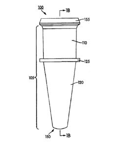
"an," and "the" include plural references unless the context clearly dictates
otherwise.
Thus, for example, references to "the method" includes one or more methods,
and/or steps
of the type described herein which will become apparent to those persons
skilled in the art
upon reading this disclosure and so forth.
[00041] The term "comprising," which is used interchangeably with "including,"
"containing," "having," or "characterized by," is inclusive or open-ended
language and does
not exclude additional, unrecited elements or method steps. The phrase
"consisting of'
excludes any element, step, or ingredient not specified in the claim. The
phrase "consisting
essentially of' limits the scope of a claim to the specified materials or
steps and those that
Date Recue/Date Received 2022-09-26
WO 2014/151996
PCT/US2014/026789
do not materially affect the basic and novel characteristics of the disclosed
subject matter.
The present disclosure contemplates exemplary embodiments of an apparatus and
methods
of use thereof corresponding to the scope of each of these phrases. Thus, an
apparatus or
method comprising recited elements or steps contemplates particular
embodiments in which
the apparatus or method consists essentially of or consists of those elements
or steps.
[00042] Unless defined otherwise, all technical and scientific terms used
herein have the
same meaning as commonly understood by one of ordinary skill in the art to
which this
disclosure belongs. Although any methods and materials similar or equivalent
to those
described herein can be used in the practice or testing disclosed herein, the
preferred
methods and materials are now described.
[00043] As used herein, a "reaction mixture" refers to a volume of fluid
comprising one
or more of a target-specific reagent, diluent for reconstituting a lyophilized
reagent, one or
more nucleotides, an enzyme, and a sample containing or suspected of
containing a nucleic
acid.
[00044] As used herein, a "sample" or a "test sample" refers to any substance
suspected
of containing a target organism or biological molecule, such as nucleic acid.
The substance
may be, for example, an unprocessed clinical specimen, a buffered medium
containing the
specimen, a medium containing the specimen and lytic agents for releasing
nucleic acid
belonging to the target organism, or a medium containing nucleic acid derived
from a target
organism which has been isolated and/or purified in a reaction receptacle or
on a reaction
material or device. In some instances, a sample or test sample may comprise a
product of a
biological specimen, such as an amplified nucleic acid to be detected.
[00045] As used herein, the term "biochemical assay" refers to a scientific
investigative
procedure for qualitatively assessing or quantitatively measuring the presence
or amount or
the functional activity of a target entity, such as, but not limited to, a
biochemical substance,
a cell, organic sample, or target nucleic acid sequence. Included in the term
"biochemical
assay" are nucleic acid amplification and heat denaturation (i.e., melting).
Nucleic acid
melting typically involves precise warming of a double stranded nucleic acid
molecule to a
Date Recue/Date Received 2022-09-26
WO 2014/151996
PCT/US2014/026789
temperature at which the two strands separate or "melt" apart. The melting
process
typically occurs at a temperature of about 50 C to about 95 C.
[00046] As used herein, the term "lyophilization" refers to a dehydration
process that is
typically used to preserve a perishable material and/or facilitate transport
thereof. Thus,
"conditions for lyophilization" refer to subjecting a liquid material and/or a
vessel
containing the liquid material to freezing conditions while reducing the
surrounding
pressure to allow the frozen water within the material to sublimate directly
from the solid
phase to the gas phase. Such freezing conditions may include cooling the
material below
the lowest temperature at which the solid and liquid phases thereof can
coexist (known in
the art as the "triple point"). Usually, the freezing temperatures are between
¨50 C and
¨80 C, however, one of skill in the art can determine the appropriate
freezing temperature
to lyophilize the reagent for use in the automated biochemical assay.
[00047] As used herein, the term "reconstituting" refers to the act of
returning a
lyophilized material to its liquid form. Thus, the term encompasses contacting
a fluid, e.g.,
water or other suitable diluent, with a lyophilized reagent for sufficient
time to allow the
lyophilized reagent to absorb water, thereby forming a stabilized liquid
reagent.
Receptacle & Cap
[00048] Accordingly, in an exemplary aspect, there is provided a receptacle
100 to receive
and store fluid test samples for subsequent analysis, including analysis with
nucleic acid-
based assays or immunoassays diagnostic for a particular pathogenic organism.
As shown
in FIGS. 1A-1D, the receptacle 100 is a single-piece receptacle that includes
a body 105
having a generally cylindrical upper portion 110 and a tapered lower portion
120. Formed
on an outer surface of the body 105 is a laterally-extending flange, which, in
the illustrated
embodiment, comprises an annular ring 125, which separates the upper and lower
portions
of the body. The upper portion 110 of the body 105 has an open end 145 through
which
fluid samples are deposited or removed from the receptacle 100. The tapered
lower portion
120 has a closed end 150 that may either be flat or rounded to provide optical
communication with an optical system, for example, one or more optical fibers
(not shown)
12
Date Recue/Date Received 2022-09-26
WO 2014/151996
PCT/US2014/026789
of a biochemical analyzer. In various embodiments, the bottom surface of the
closed-ended
lower portion may be flat or curved.
[00049] The receptacle 100 optionally containing a sample or reaction mixture
is
configured for insertion into a receptacle holder of an automated biochemical
analyzer (not
shown). As used herein, a receptacle that is "configured for insertion" refers
to the exterior
surface of the body 105 of the receptacle 100 being sized and shaped to
maximize contact
between the receptacle and a receptacle well of a receptacle holder. In
certain
embodiments, this maximal contact refers to physical contact of the receptacle
well with at
least a portion of the receptacle 100. Also in certain embodiments, this
maximal contact
refers to physical contact of the receptacle well with the tapered lower
portion 120 of the
receptacle 100, or at least a portion the tapered lower portion 120 of the
receptacle 100.
[00050] Formed in the inner surface 140 of the upper portion 110 of the body
105 is one
or more longitudinally oriented grooves 135 to facilitate the venting of air
displaced from
the interior upon deposit of the test sample or attachment of a cap 200 to the
receptacle 100.
In various embodiments, a plurality (i.e., 2, 3, 4, 5, 6, 7, or 8) of
longitudinally oriented
grooves may be formed in the inner surface 140 of the upper portion 110, and
the grooves
135 may be equally spaced apart from one another around the entire
circumference of the
body 105.
[00051] Circumscribing the open end 145 of the upper portion 110 of the body
105 is a lip
155 extending radially outward from a central axis thereof. In various
embodiments, the lip
155 tapers from the outer-most portion of the radially-extended lip towards
the open end of
the body, and is configured for securable attachment to a cap 200 (FIGS. 2A-
2D).
[00052] With reference now to FIGS. 2A-2D, the securable cap 200 includes a
lower
portion 220 having an outer surface for sealing engagement of the inner
surface 140 of the
upper portion 110 of the receptacle 100 and an upper portion 210. To ensure an
essentially
leak-proof seal when the cap 200 is securely attached to the open end 145 of
the upper
portion 110 of the receptacle 100, the outer surface of the lower portion 220
of the cap 200
is formed with one or more annular ribs 230 for contacting the inner surface
140 of the
upper portion 110 thereof. In various embodiments, the lower portion 220 of
the cap 200 is
13
Date Recue/Date Received 2022-09-26
WO 2014/151996
PCT/US2014/026789
formed with 1, 2, or 3 annular ribs 230 for contacting the inner surface 140
of the upper
portion 110 of the receptacle 100.
[00053] The upper portion 210 of the cap 200 includes an open end 215 for
frictional
attachment to a portion of a receptacle transport mechanism 300 (FIG. 3A),
such as a
tubular probe of a pipettor or pick-and-place robot. Guiding insertion of the
receptacle
transport mechanism 300 into the open end 215 of the upper portion 210 of the
cap 200 are
one or more linear ribs 260 formed in the inner surface 270 of the upper
portion 210. The
linear ribs 260 protrude towards an axial center of the cap 200, thereby
decreasing the inner
fitment diameter of the upper portion 210 of the cap 200. Each linear rib 260
may be
beveled (as at 262) at an upper, or proximal, end thereof. These linear ribs
260 can, among
other things, enhance the frictional attachment to the receptacle transport
mechanism 300.
In various embodiments, 1, 2, 3, 4, 5, 6, 7, or 8 linear ribs 260 are formed
in the inner
surface 270 of the cap 200 and extend at least a portion of the way down the
length of the
upper portion 210 thereof.
[00054] At least one of the linear ribs 260 may be formed with a portion 265
thereof, e.g.,
at a lower, or distal, end, that gradually tapers radially inward toward a
central axis of the
upper portion 210 of the cap. In other words, the amount of protrusion of the
linear rib 260
may gradually increase in size as the linear rib 260 approaches the bottom 245
of the upper
portion 210 of the cap 200. Alternatively, or in addition thereto, in certain
embodiments,
the linear rib 260 may gradually increase in overall thickness as it
approaches the bottom
245 of the upper portion 210 of the cap 200. Thus, gradual increase in
thickness or radial
geometry is contemplated for the gradual tapering of the one or more linear
ribs 260, which
serves to stabilize and center the receptacle transport mechanism 300 as it is
lowered into
the cap 200 for transport.
[00055] Corresponding with each linear rib 260 and disposed on the exterior
surface of
the upper portion 210 of the cap 200 are one or more indentations, or
recesses, 234 that
extend along at least part of the length thereof. The recesses may be formed
in any shape
such as, for example, concave, notched, squared, etc. Thus, at least one
recess 234 is
formed in the exterior surface of the upper portion 210 of the cap 200. In
various
embodiments, the length of the recess 234 is the same as the length of the
corresponding
14
Date Recue/Date Received 2022-09-26
WO 2014/151996
PCT/US2014/026789
linear rib 260, and each linear rib 260 is positioned such that it lies on the
inner surface 270
of the cap 200 in a location that directly opposes the position of the at
least one mess 234
formed on the outer surface of the cap 200 in a one-to-one relationship. The
coupling of a
linear rib 260 with an recess 234 in this manner enhances the predictability
of the frictional
attachment of the cap 200 to a receptacle transport mechanism 300. In certain
embodiments, as the receptacle transport mechanism 300 is lowered into the
open end 215
of the cap 200, it contacts the one or more linear ribs 260, thereby pressing
against the one
or more linear ribs 260. Such pressing against the linear ribs 260 causes the
cap 200, and
recesses 234 to flex and/or expand radially outward with respect to the axial
center thereof
to accommodate the receptacle transport mechanism 300 and thus enhance
frictional
attachment of the cap 300 to the receptacle transport mechanism 300.
Accordingly, 1, 2, 3,
4, 5, 6, 7, or 8 recesses 234 may be formed on the exterior surface of the
upper portion 210
of the cap 200.
[00056] Circumscribing the open end 215 of the upper portion 210 of the cap
200 is a lip
225 extending radially outward from a central axis thereof. In various
embodiments, the lip
225 tapers from the open end 215 towards the lower portion 220. Protruding
from the taper
of the lip 225 are a plurality of protrusions 235. The protrusions 235 may be
equally spaced
apart from one another and facilitate stacking and/or docking within a well of
a multi-well
tray 400 (FIG. 4A) for use in an automated biochemical analyzer. In various
embodiments,
1, 2, 3, 4, 5, 6, 7, or 8 protrusions 235 are formed in the taper of the lip
225.
[00057] In various embodiments, the cap 200 is removed from the receptacle
transport
mechanism 300 by means of a sleeve 306 coaxially disposed over a tip of the
receptacle
transport mechanism 300 and axially movable with respect to thereto. The
sleeve 306
moves axially with respect to the tip toward a distal end of the tip and
contacts the lip 225 of
the cap, thereby pushing the cap off the tip of the receptacle transport
mechanism 300.
[00058] Separating the upper portion 210 from the lower portion 220 of the cap
200 is a
flange 240 that extends radially away from an axial center thereof. The flange
240 includes
a plurality of locking arms 250 that extend from the flange 240 toward the
lower portion
220 of the cap 200. The locking arms 250 are shaped for securely engaging the
lip 155 of
the receptacle 100, and may be disposed to allow for removable attachment of
the cap 200
Date Recue/Date Received 2022-09-26
CA 3176846
to the receptacle 100, while maintaining a leak-proof seal of the content
thereof. In various embodiments,
1, 2, 3, 4,5, 6, 7, or 8 locking arms 250 are formed in the cap 200.
1000591 The flange 240 of the cap 200 additionally serves to form a bottom
245 to separate the upper
portion 210 from the lower portion 220, thereby closing the interior of the
receptacle 100 from the
environment However, in certain embodiments, the bottom 245 is scored 255 for
piercing by a
mechanism for collecting and/or adding reagents to the test sample within the
receptacle 100. Such
piercing avoids the need to remove the secured cap 200 from engagement with
the receptacle 100, while
providing access to the contents therein.
1000601 The receptacle 100 and cap 200 of the present disclosure may be
prepared from a number of
different polymer and heteropolymer resins, including, but not limited to,
polyolefins (e.g, high density
polyethylene ("HDPE"), low density polyethylene ("LDPE"), a mixture of HDPE
and LDPE, or
polypropylene), polystyrene, high impact polystyrene and polycarbonate. An
example of an HDPE is sold
under the trademark AlathonTm M5370 and is available from Polymerland of
Huntsville, N.C.; an example
of an LDPE is sold under the trademark 722TM and is available from The Dow
Chemical Company of
Midland, Mich.; and an example of a polypropylene is sold under the trademark
RexeneTm 13T10ACS279
and is available from the Huntsman Corporation of Salt Lake City, Utah.
Although LDPE is a softer, more
malleable material than HDPE, the softness of LDPE provides flexibility in the
locking arms 250 of the cap
200 to securably engage the lip 155 of the receptacle 100. And, while a cap
made of HDPE is more rigid
than one made of LDPE, this rigidity tends to make an HDPE cap more difficult
to penetrate than one made
of LDPE. It should be understood that the receptacle 100 and cap 200 may be
comprised of a combination
of resins, including, for example, a mixture of LDPE and HDPE, pieferably in a
mixture range of about
20% LDPE:80% HDPE to about 50% LDPE:50% HDPE by volume. In addition, the
amounts of LDPE
and HDPE used to form each of the receptacle 100 and cap 200 may be the same
or different In various
embodiments, at least a portion of the cap 200 is formed fiom an opaque
material having low to no
autofluorescence characteristics. Also, in certain embodiments, the portion of
the cap 200 formed from an
opaque material having low to no autofluorescence characteristics is at least
the lower portion 220 thereof,
including the inner surface 232 of the lower portion 220 of the cap 200.
16
Date recue/Date received 2023-04-06
WO 2014/151996
PCT/US2014/026789
[00061] Regardless of the type or mixture of resins chosen, the receptacle 100
and cap
200 are preferably injection molded as unitary pieces using procedures well-
known to those
skilled in the art of injection molding, including a multi-gate process for
facilitating uniform
resin flow into the receptacle and cap cavities used to form the shapes
thereof. Uniform
resin flow is desirable for achieving consistency in thickness, which is
important for a
variety of reasons, including for the penetrable bottom 245 of the cap 200; to
ensure a
secure, such as an air-tight, engagement of the cap MO and receptacle 100; to
ensure a
predictable engagement of the cap 200 with the receptacle transport mechanism
300; and to
ensure maximal contact of the receptacle 100 with a receptacle well of a
receptacle holder.
[00062] As shown in FIG. 3A, the tip of a receptacle transport mechanism 300,
(e.g., an
automated pipettor or other pick and place apparatus) may include one or more
annular ribs,
as indicated at 302 and 304, for enhancing a frictional, interference fit
between the tip 300
and a component into which the tip 300 is inserted, such as the cap 200 or a
pipette tip (not
shown). In the case of a cap, such as cap 200, the tip 300 may be inserted
into the cap and
removed from the cap several times during the course of a process that is
performed using
the cap and a receptacle to which it is attached, such as a diagnostic assay.
As the cap may
be made of a plastic material, such repeated insertion and removal of the tip
300 into and
out of the cap may result in creep in the plastic material (permanent or semi-
permanent
deformation) that can result in a poor frictional connection between the tip
300 and the cap
200.
[00063] Thus, in various embodiments, the cap may be provided with internal
relief
structures, or detents, that cooperatively engage one or both of the annular
ribs 302, 304 to
enhance the securement of the cap to the tip.
[00064] An embodiment of a cap having such a relief or detent feature is
indicated by
reference number 900 in FIG. 3C. Cap 900 includes an upper portion 910, a
lower portion
920, an annular flange 940 with locking arms 950 extending axially therefrom,
and an
opening 915 that defines an inner-surface 970. In various embodiments, cap
900, like cap
200 described above, is configured to engage a receptacle 100 by means of the
locking arms
950 engaging the lip 155 surrounding the opening of the upper portion 110 of
the receptacle
100. The cap 900 further includes a number of longitudinal ribs 960 extending
axially
17
Date Recue/Date Received 2022-09-26
WO 2014/151996
PCT/US2014/026789
along the inner surface 970. In various embodiments, the ribs 960 are
equiangularly spaced
about the inner surface 970. In one embodiment, each rib 960 has associated
therewith a
longitudinally-extending indention, or recess, 934 formed on an exterior
surface of the
upper portion 910 opposite the rib 960. The recess 934 may be in the form of a
longitudinally extending, concave groove, which, in various embodiments, may
be the same
length as the rib 960. Each rib 960 includes an enlarged portion 965 at a
lower distal end
thereof. In one embodiment, the rib 960 incudes a tapered transition between
the upper
narrower portion of the rib 960 and the larger lower portion 965. Larger
portion 965 may
extend through a transition between the generally cylindrical inner surface
970 of the upper
portion 910 and a tapered, e.g., conical, surface 972.
[00065] As discussed elsewhere in this disclosure, in various embodiments each
rib 960
and associated recess 934 cooperate to allow radial flexure of the rib 960
that enables the rib
to conform to the general shape of a portion of a receptacle transfer
mechanism inserted into
the cap 900.
[00066] One or more of the longitudinal ribs 960 further includes a relief, or
detent, 964
defined as a portion of the enlarged section 965 of the rib 960 that is
removed or scalloped
out, as shown in FIG. 3C to define a concave recess or cavity in the lower end
of the rib
960. As shown in FIG. 3D, each relief 964 receives the lower annular rib 302
of the
receptacle transport mechanism 300. The inter engagement of the annular rib
302 with the
relief 964 enhances the frictional securing of the cap 900 to the receptacle
transport
mechanism 300.
[00067] In various embodiments, a detent 964 is formed in every one of the
longitudinal
ribs 960.
[00068] An alternate embodiment of a cap having a relief, or detent, feature
for securing
the cap to a receptacle transport mechanism is indicated by reference number
1000 in FIG.
3E. Cap 1000 includes an upper portion 1010 and a lower portion 1020. An
annular flange
1040 extends radially from the cap 1000 and has a plurality of locking arms
1050 extending
axially therefrom. In various embodiments, cap 1000 is configured to interlock
with a
18
Date Recue/Date Received 2022-09-26
WO 2014/151996
PCT/US2014/026789
receptacle 100 by means of the locking arms 1050 engaging a lip 155
surrounding an
opening at the upper end 110 of the receptacle 100.
[00069] Cap 1000 has a number of longitudinal ribs 1060 extending axially
along an inner
surface of the upper portion 1010. In various embodiments, the ribs 1060 are
equiangularly
spaced about the inner surface of the upper portion. In one embodiment, each
rib 1060 has
associated therewith a longitudinally-extending indention or recess 1034
fonned on an
exterior surface of the upper portion 1010 opposite the rib 1060. The recess
1034 may be in
the form of a longitudinally extending, concave groove, which, in various
embodiments,
may be the same length as the rib 1060.
[00070] In various embodiments, each rib 1060 transitions into an enlarged,
portion 1065
near a lower, distal end thereof. Various embodiments may include a tapered
transition
between the enlarged portion 1065 and a non-enlarged portion of the rib 1060.
[00071] As discussed elsewhere in this disclosure, in various embodiments each
rib 1060
and associated recess 1034 cooperate to allow radial flexure of the rib 1060
that enables the
rib to conform to the general shape of a portion of a receptacle transfer
mechanism inserted
into the cap 1000.
[00072] A relief, or detent, is provided in one or more of the ribs 1060 by a
window, or
opening, 1064 cutout of the cap 1000 near the transition between the upper,
relatively
straight-sided surface 1070 and the lower, tapered portion 1072 of the upper
portion 1010.
As shown in FIG. 3E, each opening 1064, combined with the enlarged portion
1065 of the
rib 1060 located directly above each opening 1064, forms a relief or detent
that receives the
lower annular rib 302 of the receptacle transport mechanism 300. In various
embodiments,
an opening 1064 is provided in each of at least two ribs 960. In various
embodiments, two
openings 1064 are provided at diametrically opposed positions.
[00073] The relief, or detent structure, provided by the opening 1064 of cap
1000 or the
relief 964 or detent of cap 900 physically engages a portion of the tip 300,
such as the
annular rib 302, to frictionally secure the cap 900, 1000 on to the receptacle
transport
mechanism 300 with minimal or no deformation of the plastic material in the
vicinity of the
relief, thereby avoiding or limiting creep of the plastic material in the
vicinity of the detent.
19
Date Recue/Date Received 2022-09-26
WO 2014/151996
PCT/US2014/026789
Method for Automated Removal of a Cap
[00074] Occasionally, after process is performed on the cap-receptacle
assembly and its
contents, such as, for example, centrifugation or incubation under isothermal
or
thermocycling conditions, it is necessary to access the interior of the
receptacle to remove
substances therefrom and/or to add substances thereto. Accordingly, in such
instances, it
becomes necessary to remove the cap 200 (or 900 or 100), from the receptacle
100 to
which it is lockingly attached.
[00075] In another aspect, disclosed herein is a method for automated removal
of a cap
from a capped reaction receptacle. The method includes providing a receptacle
100
securably engaging the lip 155 of a receptacle 100, as shown in FIG. 3B.
Thereafter,
performing an automated motion of contacting an inner portion 280 of at least
one of the
plurality of locking arms 250 of the cap 200 with a raised annular ridge
defined around a
receptacle slot. The receptacle slot may be provided in a receptacle holder of
an automated
biochemical analyzer, alternatively the receptacle slot may be provided in a
card or
cartridge intended to be removed from an automated biochemical analyzer. The
contacting
urges the locking arms 250 away from the lip 155 of the receptacle 100,
thereby
disengaging the cap 200 from the receptacle 100. While the cap 200 is being
disengaged
from the receptacle 100, an automated motion is performed to lift the cap 200
away from
the receptacle 100, thereby removing the cap 200 from the receptacle 100. In
various
embodiments, the automated motion is performed by a receptacle transport
mechanism 300
(FIG. 3A), such as, for example, a pipettor or pick-and-place robot.
[00076] An apparatus for removing a cap from a receptacle in an automated
fashion is
indicated by reference number 1260 in FIGS. 12 and 13. FIGS. 12 and 13 are
partial top
and bottom perspective views, respectively, of a cap removal tray 1260. The
tray 1260
includes a base 1262 generally surrounding the tray, and a top wall 1264
supported on the
base 1262. An assembly comprising the cap 200 and receptacle 100 is shown
inserted into
one of the plurality of cap removal stations 1266 for removing the cap 200
from the
receptacle 100, as will be described below. As shown in FIG. 13, when inserted
into an
opening 1268 of the cap removal station 1266, the receptacle 100 extends below
the top
wall 1264. Accordingly, in a preferred embodiment, the base 1262 has
sufficient height to
Date Recue/Date Received 2022-09-26
WO 2014/151996
PCT/US2014/026789
accommodate the length of the receptacle 100 projecting through the cap
removal station
1266 and beneath the top wall 1264.
[00077] In FIGS. 12 and 13, which are partial views of the cap removal tray
1260, a
matrix of nine cap removal stations 1266 is shown. The cap removal tray 1260
may have
any number of cap removal stations 1266. In various embodiments, the cap
removal
stations 1266 are oriented in aligned rows and columns. As will be described
below, after
the cap 200 is removed from the receptacle 100, the receptacle 100 remains
within the cap
removal station 1266. Accordingly, by orienting the cap removal stations 1266
in aligned
rows and columns, a spatially indexed orientation is provided so that a
receptacle transport
mechanism (e.g., an automated pipettor) can accurately identify and/or access
any of the
receptacles retained within the cap removal tray 1260.
[00078] Each cap removal station includes a raised collar 1270 surrounding the
opening
1268 and extending above the top wall 1264. A plurality of resilient tabs
1272, e.g., four,
surround the opening 1268 and extend below the top wall 1264. In various
embodiments,
each of the tabs 1272 is angled radially inwardly relative to the center of
the opening 1268.
[00079] The manner in which a cap is removed from a receptacle by the cap
removal
station 1266 is shown by the sequence illustrated in FIGS. 14A, 14B, 14C.
[00080] As shown in FIG. 14A, when an assembly comprising a cap 200 and
receptacle
of 100 is inserted though the opening 1268 of a cap removal station 1266 the
annular ring
125 formed on the receptacle 100 engages the lower ends of the resilient tabs
1272, which
are angled inwardly so that the distance between the tabs at their lower or
distal ends 1274
is less than the diameter of the annular ring 125. The force of the annular
ring 125 being
pushed through the resilient tabs 1272 pushes the tabs outwardly, as shown in
FIG. 14A, to
thereby permit the receptacle to be pushed through the tabs 1272.
[00081] The raised collar 1270 has an outer surface that angles away from the
opening
1268 with a larger width (e.g., diameter) at the base of the collar than at
the tip of the collar
and is configured so that the top edge of the raised collar 1270 will fit
inside the nndeflected
locking arms 250 of the cap 200 to contact the an inner portion 280 (see FIG.
2B) of the
locking arms 250.
21
Date Recue/Date Received 2022-09-26
CA 3176846
[00082] As shown in FIG. 14B as receptacle 100 is pushed through the
opening 1268 the locking arms
250 slide along the exterior surface of the raised collar 1270, which is
angled outwardly progressing from the
top of the collar to the base of the collar, thereby pushing the locking arms
outwardly, out of engagement with
the lip 155 of the receptacle 100. Further, as the annular ring 125 of the
receptacle 100 clears the lower ends
1274 of the resilient tabs 1272, the tabs 1272 snap resiliently toward their
undeflected positions bearing
against an outer surface the receptacle 100 above the annular ring 125.
[00083] The lip 155 of the receptacle 100 is spaced apart from the annular
ring 125 of the receptacle
100 by a distance generally corresponding to the distance between the top
edge, or upper tip, of the raised
collar 1270 and the lower ends 1274 of the resilient tabs 1272. Moreover, the
width, or diameter, of the
upper edge of the raised collar 1270 generally corresponds to the width, or
diameter, of the lip 155
surrounding the opening of the receptacle. Thus, the receptacle 100 continues
to be moved through the
opening 1268, the angled outer surface of the raised collar 1270 moves the
locking arms 250 out of
engagement with the lip 155, and the lip 155 into contact with the top edge of
the raised collar 1270. At
this time, the annular ring 125 of the receptacle 100 clears the lower ends
1274 of the resilient tabs 1272.
The receptacle is then essentially locked within the cap removal station 1266,
with the resilient tabs 1272
and the raised collar 1270 disposed between the lip 155 and the annular ring
125. The contact between the
underside of the lip 155 and the top edge of the raised collar 1270 prevents
the locking arms 250 from
reengaging the lip 155.
[000841 As shown in FIG. 14C, when the cap 200 is then raised, its locking
aims 250 are no longer
engaged with the lip 155 of the receptacle 100, and the receptacle 100 is
retained within the cap removal
station 1266 by the annular ring 125 in contact with the lower ends 1274 of
the resilient tabs 1272. Thus, the
cap 200 can be separated from the receptacle 100, and the receptacle 100 is
retained within the cap ieffloval
station 1266 of the cap removal tray 1260.
[00085] Although the cap removal stations 1266 of the cap removal tray 1260
and the cap 200 and
receptacle 100 are shown as having generally circular shapes, the concepts
embodied in the cap
removal stations 1266 are applicable to different shapes. For example,
22
Date recue/Date received 2023-04-06
WO 2014/151996
PCT/US2014/026789
a cap removal station may have a rectangular shape for remove a cap having
similar a
rectangular shape from a receptacle also having a similar rectangular shape.
[00086] In various embodiments, the cap removal tray 1260 comprises an
integrally-
molded plastic component, and raised collar 1270 and resilient tabs 1272 of
each cap
removal station 1266 are integrally formed within the top wall 1264.
Multi-Well Tray
[00087] In another aspect, disclosed herein is a multi-well tray for use in an
automated
process. Referring now to FIGS. 4A and 4B, a multi-well tray 400, as shown,
includes a
base 410 having disposed in a top surface 417 thereof, a plurality of wells
415, 416. A card
insert 420 (see also FIG. 5A) configured for removable attachment to the base
410, is
attached thereto. When the card insert 420 is attached to the base 410, a top
surface 425 of
the card insert 420 is substantially parallel to and flush with the top
surface 417 of the base
410.
[00088] Disposed in the top surface 425 of the card insert 420, is a plurality
of wells 430,
each configured for containing one or more reagents used for performing a
biochemical
analysis. Each well 430 of the card insert 420 corresponds to at least one of
the wells 415
disposed in the base 410. Thus, in certain embodiments, after attachment of
the card insert
420 to the base 410, the multi-well tray 400 takes on the uniform appearance
of, for
example, a multi-well plate. The wells 415, 416 disposed in the base 410 may
be arranged
in pairs, where each pair corresponds to a single well 430 of the card insert
420. As such,
the multi-well tray 400 may include a plurality of sets 435 of wells, where
each set 435
includes a first well 415 and a second well 416, which arc disposed in the top
surface 417 of
the base 410, and a third well 430 disposed in the top surface 425 of the card
insert 420.
The wells of each set 435 of wells may be in alignment with each other,
thereby resulting in
a multi-well tray 400 that is spatially indexed such than an automated
receptacle transport
mechanism 300 can accurately identify and/or access any of the plurality of
wells when the
multi-well tray 400 is placed or inserted into an automated system. In certain
embodiments,
the multi-well tray 400 includes ten sets 435 of wells. As such, the base 410
is formed with
ten pairs of first and second wells 415, 416 and the card insert 420 is formed
with ten third
23
Date Recue/Date Received 2022-09-26
CA 3176846
wells 430, where each of the first, second, and third wells of the set 435 are
arranged in alignment with each
other. Thus, the multi-well tray 400 may include ten receptacles 100 and ten
caps 200 provided therein for
used in an automated biochemical analyzer.
[00089] The first and second wells 415, 416 of the set 435 are configured
to receive a cap 200 and a
receptacle 100, respectively. While it should be understood that the terms
"first" and "second" as used to
distinguish the wells foimed in the base 410, for descriptive purposes, the
"first well", or cap well, 415 will
refer to a well configured to receive a receptacle cap 200.
[00090] With reference now to FIGS. 7A and 7B, the first well 415 of the
base 410 is defined by a
cylindrical wall 470 and a bottom wall 472. Formed in the center of the bottom
surface 472 is a protrusion
475 extending upwardly toward the top surface 417 of the base 410. The
protrusion 475 is sized and
shaped for engagement, optionally frictional engagement, with a hollow portion
233 of the lower portion
220 of the cap 200. Alternatively, or in addition thereto, the cylindrical
wall 470 may be formed with a
plurality of tabs 477 protruding towards the axial center of the first well
415. Such tabs 477 are configured
for securely engaging at least a portion of the cap 200 to prevent the cap 200
from dislodging from the
multi-well tray if, for example, the multi-well tray is inverted or shaken. In
certain embodiments, 2, 3, 4,
5, 6, 7, or 8 tabs 477 are formed in the cylindrical wall 470 of the first
well. Each of tabs 477 may securely
engage the top surface of the flange 240 of the cap 200.
[00091] Similarly, the "second well", or receptacle well, 416 will refer to
a well configured to receive
a receptacle 100. As shown in FIGS. 7A and 7B, the second well 416 is defined
by a cylindrical wall 480
and a bottom wall 482. Formed in the center of the bottom wall 482 is a
through-hole 485base. The
through-hole 485 is sized and shaped in conformance with the outer surface of
the lower portion 120 of the
receptacle 100. As such, the through-hole may be tapered at an angle
corresponding to the angle of the
lower portion 120. As shown in FIG. 7A, the bottom wall 482 of the second well
416 forms an annular
ledge at the perimeter of the through-hole for engaging the ring 125 of the
receptacle 100. Alternatively, or
in addition thereto, the cylindrical wall 480 may be formed with a plurality
of legs 487 protruding towards
the axial center of the second well 416.
24
Date recue/Date received 2023-04-06
WO 2014/151996
PCT/US2014/026789
Such legs 487 are configured for securely engaging at least a portion of the
receptacle 100
to prevent the receptacle 100 from dislodging from the multi-well tray if, for
example, the
multi-well tray is inverted or shaken. In certain embodiments, 2, 3, 4, 5, 6,
7, or 8 legs 487
are formed in the cylindrical wall 480 of the second well 416. Each of the
legs 487 may
securely engage the top surface of the ring 125 of the receptacle 100.
[00092] As discussed above, the third well, or reagent well, 430 of each set
435 contains
one or more reagents for performing a biochemical analysis. In certain
embodiments, the
third well 430 of the set 435 contains a lyophilized reagent 495 (FIGS. 8 and
9C), and may
be sealed with a frangible seal 440 (FIG. 8). For example, each well 430 of
the card insert
420 may be sealed with a metallic foil (or foil laminate) using, for example,
a pressure
sensitive adhesive which is applied to the top surface 425 thereof. The
frangible seal 440
may further include a plastic liner, such as a thin veneer of HDPE applied to
one or both
surfaces thereof, which promotes attachment of the frangible seal 440 to the
top surface 425
when a heat sealer is used. Heat sealing is a well-known process and involves
the
generation of heat and the application of pressure to the surface being
sealed, which, in this
case, is the top surface 425 or a raised lip 427 (see FIGS. 4A, 5A)
surrounding the well 430
of the card insert 420. Alternatively, any known ultrasonic welding procedure
using either
high frequency or high amplitude sound waves may also be used to affix the
frangible seal
4.40 to the card insert 420. The card insert 420 may include a plurality of
frangible seals
440, each of which sealing a single well 430, or may include a single sheet
that seals all
wells 430 disposed therein.
[00093] A single lyophilized reagent 495 may be provided in each well 430 of
the card
insert 420. However, in certain embodiments, one or more wells 430 of the card
insert 420
may contain a different lyophilized reagent 495, such as a different target-
specific reagent.
Thus, each well 430 of the card insert 420 may contain a distinct lyophilized
reagent 495
compared with the lyophilized reagent 495 contained in at least one other of
the plurality of
wells 430 therein. In various embodiments, the card insert 420 does not
contain non-
reagent consumables. As used herein, a "reagent" refers to a substance or
mixture for use in
a chemical or biochemical reaction. Thus, a "non-reagent consumable" refers to
a
component that is used by an automated biochemical assay, but is not a
reagent. Exemplary
Date Recue/Date Received 2022-09-26
WO 2014/151996
PCT/US2014/026789
non-reagent consumables include, but are not limited to, contamination
limiting elements,
receptacles 100, and caps 200.
[00094] Referring now to FIGS. 5A-5E, each well 430 of the card insert 420 is
defmed by
a side wall, or well wall, 450 and a bottom, or bottom wall or bottom wall
portion, 455. In
various embodiments, the side wall 450 tapers from an upper end thereof to the
bottom 455,
and may therefore be referred to as a conical wall. As shown in FIGS. 5B-5E,
the bottom
455 of each well may be formed with one or more features to facilitate deposit
of and
collection of fluid from the well. Such features include, but are not limited
to a concave
groove 457, 460 (FIGS. 5C, 5D, 5E), convex ridge (not shown), or a set of
grooves
positioned in a crisscross pattern (not shown). The features may be located at
the axial
center of the well 430, as shown in FIG. 5C, or may be off-set to a side
thereof, as shown in
FIG. 5B. Alternatively, or in addition thereto, the side wall 450 may be
formed with a
plurality of bumps 462 on the surface thereof for additional facilitation of
depositing and/or
collecting fluids contained therein. The side wall 450 of each well 430 of the
card insert
420 may further be formed with a plurality of rigid guides 465 that protrude
radially from
the side wall 450 towards the axial center of the well 430. Such rigid guides
465 guide a
pipette tip 310 (FIGS. 8 and 9C) mounted on an automated pipettor toward the
axial center
of the well 430 as the tip is lowered therein, and may further serve to retain
the lyophilized
reagent at, or adjacent to, the bottom 455 of the well 430. In various
embodiments, each
well 430 may be independently formed with 2, 3, 4, 5, 6,7, or 8 rigid guides
465 protruding
from the respective tapered side wall 450.
[00095] The features formed at the bottom 455 of the well 430, such as
grooves, ridges,
and/or bumps, interfere with the end of a pipette tip inserted into the well
430 and thus
prevent the end of the pipette tip from making sealing contact with the bottom
455 so as to
prevent a negative pressure build up within the pipette tip during a fluid
aspiration. For
example, as shown in FIG. 5E, a feature formed on the bottom 455 of well 430,
such as
groove 457, provides a clearance that prevents a pipette tip 310 from making
sealing contact
with the bottom 455 of the well 430.
[00096] Additionally, in certain embodiments, the side wall 450 of each well
430 of the
card insert 420 may include one or more retention features (FIGS. 8, and 9C-
9D) that can be
26
Date Recue/Date Received 2022-09-26
WO 2014/151996
PCT/US2014/026789
used to retain the lyophilized reagent 495 at, or adjacent to, the bottom 455
of the well 430
when, for example a diluent is deposited into the well 430 for reconstitution
of a lyophilized
reagent. In FIGS. 9C and 9D, the retention features are shown within a well
715 of an
alternative embodiment of a multi-well tray 700 described below. In various
embodiments,
the retention feature may include one or more protrusions or an annular ridge
800 formed
above the area to be occupied by the lyophilized reagent 495, and extending
toward the
axial center of the well 430. Such protrusions or annular ridge 800 narrow the
opening of
the side wall 450 such that the opening is smaller than the diameter of the
lyophilized
reagent 495.
[00097] As shown in FIG. 9E, the annular ridge 800 may be formed by inserting
one or
more heat stakes 880 into the wells 430, such that the side wall 450 is
deformed, thereby
forming an annular ridge 800 therein. The one or more heat stakes 880 may be
attached to
an apparatus 890, which may heat the one or more heat stakes 880, thereby
providing
sufficient heat to deform the side wall 450 at a point along the taper where
the diameter
thereof equals that of the diameter of the heat stake.
[00098] In various embodiments, the retention feature may also take the form
of one or
more solid extensions 810 formed over the area to be occupied by the
lyophilized reagent
495. Such extensions 810 connect opposing areas of the side wall 450, thereby
retaining the
lyophilized reagent 495 at, or adjacent to, the bottom 455 of the well 430. In
various
embodiments, the side wall 450 may be formed to mimic the thread of a coarse
screw as
shown at 820. Such a threaded feature 820 may be formed during injection
molding of the
well 430, or may be formed by applying a heated screw portion to the well
wall, thereby
forming a spiral channel along a length thereof, through which fluid may run
to the bottom
455 using gravitational force. In various embodiments, the retention feature
may be
provided in the form of a tapered ring insert 830 that is fixedly attached to
the side wall 450
either before or after deposit of the lyophilized reagent 495. The tapered
ring 830 may be
formed of plastic and include an exterior surface that tapers in accordance
with the taper of
the side wall 450. When present, the tapered ring 830 narrows the opening of
the well 430
such that the lyophilized reagent 495 is retained at, or adjacent to, the
bottom 455 of the
well 430.
27
Date Recue/Date Received 2022-09-26
WO 2014/151996
PCT/US2014/026789
[00099] Whether the lyophilized bead 495 is formed within the well from an
initially
liquid reagent or the solid bead is formed outside the well and then placed
into the well may
depend on whether the retention feature is an integral part of the well. If
the retention
feature is an integral part of the well, a solid bead could not be placed into
the well below
the retention feature and a liquid reagent must be dispensed into the bottom
of the well and
then lyophilized. If the retention feature is not an integral part of the
well, a lyophilized
bead could be placed into the well, and then the retention feature installed
in the well over
the lyophilized bead.
[000100] As shown in FIG. 9D, the inner surface of a well wall may be
substantially
vertical as at 840, while an exterior surface of the well retains its tapered
shape. In certain
embodiments, the inner surface of the well wall may be substantially vertical
as at 840,
while the exterior surface of the well is also substantially vertical (not
shown). When
present, the vertical wall 840 allows the entirety of a liquid reagent to be
lyophilized to
settle at the bottom 455 of the well, thereby ensuring reagent uniformity upon
[000101] In various embodiments, as also shown in FIG. 9D, the retention
feature may be
in the form of a capillary insert 850 that is fixedly attached to the well
wall. The capillary
insert 850 may be formed of plastic and include an exterior surface that
tapers in accordance
with the taper of the well wall. In an exemplary embodiment, the well and
capillary insert
850 may be formed as a single unit. The capillary insert 850 may not extend
completely to
the bottom of the well, thereby defining a chamber 856 below a bottom end of
the capillary
insert 850. The inner surface of the capillary insert 850 may include
substantially vertical
walls forming a capillary channel 852 extending from an upper end of the
insert to a lower
end of the insert through which fluid will flow via capillary attraction, and
within which the
fluid will be retained as a result of the combination of surface tension and
adhesive forces
between the fluid and the walls of the capillary channel. The capillary insert
850 may
further include an open upper end 854 that tapers from a top surface of the
insert 850 to the
channel 852. Thus, when a capillary insert 850 is present in a well and a
liquid reagent to
be lyophilized is deposit therein, the reagent remains held within the
capillary channel
thereof, and is prevented from flowing into the bottom of the well. After
lyophilizing the
liquid reagent, the lyophilized reagent 495 remains lodged within the channel
852 of the
28
Date Recue/Date Received 2022-09-26
WO 2014/151996
PCT/US2014/026789
capillary insert 850. Deposit of a diluent for reconstitution of the
lyophilized reagent 495 is
accomplished by addition of the diluent to the tapered open upper end 854 of
the capillary
insert 850. The diluent then flows within the capillary channel 852 via
capillary attraction,
and is retained therein as a result of the combination of surface tension and
adhesive forces
between the diluent and the walls of the capillary channel 852. Once
reconstituted, the
reagent may be collected by insertion of the pipette tip 310 into the tapered
open upper end
854 of the capillary insert 850 and withdrawing the liquid reagent therefrom.
The entirety
of the liquid reagent may therefore be collected at the tapered open upper end
854 of the
capillary insert 850 since the liquid will travel upwards due to capillary
attraction within the
channel 852 of the capillary insert 850.
[000102] Alternatively, or in addition thereto, the bottom 455 of the well can
be formed to
include a roughened surface, thereby providing sufficient surface area to
which the
lyophilized reagent 495 will adhere upon formation thereof. Alternatively, or
in addition
thereto, the lyophilized reagent 495 will adhere to, or adjacent to, the
bottom 455 of the well
430 through a static electrical attractive force created on the well wall 450
and/or bottom
455 of the well 430. In such embodiments, the inner surface of the well 430 is
provided
with an electrical charge such that the lyophilized reagent 495 adheres
thereto.
[000103] In various embodiments, the retention feature may take the form of an
insert
through which the pipette tip 310 may be inserted. For example, as shown in
FIG. 9D the
retention feature may be a fingered collar 860 that is fixedly attached to a
top portion of the
well. The fingered collar 860 may be formed of plastic and include an exterior
surface that
tapers in accordance with the taper of the well wall. The fingered collar 860
may include
one or more (i.e., 1, 2, 3, 4, 5, 6, 7, or 8) fmgers extending from a bottom
surface thereof,
and protruding along a radius of curvature toward the axial center of the
well. The one or
more fingers may be flexible such that contact with a pipette tip 310 inserted
therein causes
the fingers to flex toward the well wall, thereby allowing the pipette tip 310
to pass there
through. Upon withdrawal of the pipette tip 310, the fingers return to a rest
position such
that the fingers protrude along the radius of curvature toward the axial
center of the well.
[000104] In an alternative embodiment, the retention feature may take the form
of a collar
870 that resembles the fingered collar 860, but does not include the one or
more fingers
29
Date Recue/Date Received 2022-09-26
WO 2014/151996
PCT/US2014/026789
protruding therefrom. Such a collar 870 may be fixedly attached to a top or
center portion
of the well wall, and may be formed of plastic and include an exterior surface
that tapers in
conformance with the taper of the well wall. When present, the collar 870
narrows the well
wall to retain the lyophilized reagent 495 at, or adjacent to, the bottom 455
of the well,
while allowing the pipette tip 310 to pass there through.
[000105] Each of the base 410 and card insert 420 may be independently
constructed of an
injection molded plastic, such as the plastics described above. The plastic
used to form the
base 410 may be the same or different from the plastic used to form the card
insert 420. For
example, the card insert 420 may be formed from a plastic having lower
permeability to air
and/or moisture than the plastic forming the base 410. Such plastics may be
more
expensive than their conventional counterparts but, due to the decreased air
and moisture
permeability, provide for enhanced stability of reagents, such as lyophilized
reagents
contained in the wells thereof. Any exterior surface of the base 410 or card
insert 420 may
further include one or more identifying labels 490, such as a barcode, 2D
barcode, quick
response (QR) code, radio frequency identification (RFM), or other human or
machine
readable indicia, disposed thereon. The information carried on such label may
include
identifying information regarding the multi-well tray 400 and/or card insert
420, including
information regarding the reagents contained therein, such as lot number,
serial number,
assay type, expiration date, etc. In various embodiments, the base 410 may
include one or
more barcodes and/or QR codes on a side surface thereof for identifying assays
to be
performed by the automated biochemical analyzer.
[000106] As shown in FIG. 4B, the base 410 may be formed with one or more
locking
arms 445 positioned for locking engagement with the card insert 420.
Additionally, the
card insert 420 may be formed with one or more corresponding lock-holes 447
for receiving
the locking arms 445 of the base 410. Once secured into the base 410 by the
locking arms
445 and/or the lock-holes 447, the card insert 420 is prevented from
detachment therefrom.
However, in certain embodiments, locking arms 445 may be moved out of locking
engagement with the card insert 420 to release the card insert 420 from the
base 410. Such
releasable engagement provides for reuse of the base 410, if necessary, and/or
replacement
of a card insert 420 should the need arise.
Date Recue/Date Received 2022-09-26
WO 2014/151996
PCT/1JS2014/026789
[000107] As shown in FIG. 6A, base 410 may be further formed with one or more
locking
fingers 422 disposed on a side surface thereof. The locking fingers 422 are
configured for
releasably engaging a rack to secure the base 410 to the rack for use in
automated
processing. In various embodiments, the base 410 may further include a release
437 for
urging the locking fingers 422 away from the engaging surface of the rack to
facilitate
removal therefrom.
[000108] As shown in FIG. 6B, the card insert 420 may be secured to the base
410 by
means of locking features 424 disposed along opposed sides of the card insert
420 that are
configured for locking engagement with cooperating ledges 412 formed in the
base 410
[000109] FIGS. 9A-9E show an alternative embodiment of a multi-well tray 700.
Referring now to FIGS. 9A and 98, the multi-well tray 700 includes a base 710
having
disposed in a top surface 717 thereof, a plurality of wells 715. The base 710
also includes
an arm 720 for engagement by a transport mechanism, such as a rotary
distributor (not
shown) for transport within an automated biochemical analyzer. As shown in
FIG. 9B, the
bottom surface 730 of the base 710 is formed with one or more snap fingers
735, which
define a slot 740 into which an clement (not shown) of the biochemical
analyzer is inserted.
Thus, snap fingers 735 grasp the element (not shown) of the biochemical
analyzer, thereby
forming a secure attachment thereto.
[000110] In this alternative embodiment, all of the wells 715 are configured
to contain one
or more reagents used for performing automated biochemical analysis. Similar
to the wells
430 of the multi-well tray insert 420, each well 715 is defined by an inner
side wall 750 and
a bottom 755. In various embodiments, the side wall 750 tapers from a top
portion of the
well 715 to the bottom 755, as shown in FIG. 9C.
[000111] As discussed above, the bottom 755 of each well 715 may be formed
with one or
more features to facilitate deposit of and collection of fluid from the well.
Such features
include, but not limited to a concave groove 457, 460 (FIGS. 5B-5D), a convex
ridge (not
shown), or a set of grooves positioned in a crisscross pattern (not shown).
The features may
be located at the axial center of the well 715, as shown in FIG. 5C, or may be
off-set to a
side thereof, as shown in FIG. 5B. Alternatively, or in addition thereto, the
inner wall 750
31
Date Recue/Date Received 2022-09-26
WO 2014/151996
PCT/US2014/026789
may be formed with a plurality of bumps 462 (FIGS. 5B-5D) on the surface
thereof for
additional facilitation of depositing and/or collecting fluids contained
therein. The inner
wall 750 of each well 715 of the card 700 may further be formed with a
plurality of rigid
guides 465 (FIG. 5B) that protrude radially from the inner wall 750 towards
the axial center
of the well 715. Such rigid guides 465 guide the tip 310 (FIGS. 8 and 9C)
mounted on an
automated pipettor toward the axial center of the well 715 as the tip is
lowered therein, and
may further serve to retain the lyophilized reagent 495 at, or adjacent to,
the bottom 755 of
the well 715. In various embodiments, each well 715 may be independently
formed with 2,
3,4, 5, 6, 7, or 8 rigid guides protruding from the respective tapered well
wall 750.
[000112] Additionally, in certain embodiments, the inner well walls 750 of
each well 715
of the card 700 may include one or more retention features 800, 810, 820, 830,
840, 850,
860, 870 (FIGS. 8 and 9C-9D), as described above, configured to retain the
lyophilized
reagent 495 at, or adjacent to, the bottom 755 of the well 715 when, for
example a diluent is
deposited into the well 715 for reconstitution. In various embodiments, the
retention
features may include an annular ridge 800 formed above the area to be occupied
by the
lyophilized reagent 495, and extending toward the axial center of the well
715. In various
embodiments, the retention features may also take the form of one or more
solid extensions
810 formed over the area to be occupied by the lyophilized reagent 495. Such
extensions
810 connect opposing areas of the well wall 750, thereby retaining the
lyophilized reagent
495 at, or adjacent to, the bottom 755 of the well 715. In various
embodiments, the well
715 may include any of the various inserts 830, 850, 860, or 870, as discussed
above.
Alternatively, or in addition thereto, the well wall '750 may be a vertical
wall 840 or may be
formed to include a screw thread (i.e., a spiral channel) 820. Alternatively,
or in addition
thereto, the bottom 755 of the well can be formed to include a rough surface,
thereby
providing sufficient surface area to which the lyophilized reagent 495 will
adhere upon
formation thereof. Alternatively, or in addition thereto, the lyophilized
reagent 495 will
adhere to the bottom 755 of the well 715 Ibrou a stalk electrical attractive
force created
on the well wall 750 and/or bottom 755 of the well 715.
Cartridge With Communicating Wells
32
Date Recue/Date Received 2022-09-26
WO 2014/151996
PCT/US2014/026789
[000113] In another aspect of the disclosure, a cartridge 500 with
communicating wells for
use in an automated process is shown in FIGS. 10A and 10B, which depict
different
alternative cartridge embodiments. The cartridge 500 includes a casing 510
having a top
surface 517, a fluid chamber 520, and a fluid reservoir 515. In various
embodiment, the
fluid chamber 520 and the fluid reservoir 515 comprise wells open at the top
surface 517.
In various embodiments, as reflected in the drawings, the fluid chamber 520
has a smaller
volumetric capacity than the fluid reservoir 515. As further reflected in the
drawings, the
perimeter of the open end of the fluid chamber 520 may be smaller than the
perimeter of the
open end of the fluid reservoir 515, and thus the exposed surface of a fluid
in the fluid
chamber 520 would be smaller than the exposed surface of a fluid in the fluid
reservoir 515.
[000114] The fluid chamber 520 and the fluid reservoir 515 may contain the
same liquid,
such as a diluent or a reconstitution solution for reconstituting the
lyophilized reagent (e.g.,
lyophilized reagent 495).
[000115] The cartridge 500 may be provided with one or more fluid connections
between
the fluid chamber 520 and the fluid reservoir 515. Thus, in various
embodiments, one or
more openings 525 and/or 527 between the fluid chamber 520 and the fluid
reservoir 515
may include one or more channels between the fluid reservoir 515 and the fluid
chamber
520 to provide a path through which a liquid or gas may flow between the fluid
chamber
520 and the fluid reservoir 515. An opening, such as opening 527, between the
fluid
chamber 520 and the fluid reservoir 515 may be provided by a slot or hole
formed in a wall
separating the fluid chamber 520 and the fluid reservoir 515.
[000116] In various embodiments, a first opening 525 is provided proximate a
lower
portion of the fluid chamber 520 and the fluid reservoir 515 (e.g., at a base
of the casing
510) for fluid communication between the fluid chamber 520 and the fluid
reservoir 515,
and a second opening 527 is provided proximate an upper end (i.e., near the
open ends) of
the fluid chamber 520 and the fluid reservoir 515 for fluid communication
between the fluid
chamber 520 and the fluid reservoir 515.
[000117] As shown in FIG. 10A, the cartridge 500 may also include a second
fluid
reservoir 530 disposed within the casing and adjacent to the fluid chamber
520. The second
33
Date Recue/Date Received 2022-09-26
WO 2014/151996
PCT/US2014/026789
reservoir 530 can be utilized to store the same or a different liquid than is
stored in reservoir
515. In certain embodiments the second reservoir 530 is not in fluid
communication with
the fluid reservoir 515 or the fluid chamber 520. In certain embodiments the
fluid reservoir
515 and the fluid chamber 520 contain a reconstitution solution, and the
second reservoir
530 contains oil.
[000118] In various embodiments, each of the fluid chamber 520, fluid
reservoir 515, and
second reservoir 530 may be sealed with a seal (not shown), such as a metallic
foil (or foil
laminate). A seal over the fluid reservoir 515, the fluid chamber 520, and/or
the second
reservoir 530 may be provided to prevent spillage of fluid contents in case
cartridge 500 is
tipped, dropped, shaken, or inverted, The seal also prevents or retards
evaporation of the
fluid contents of the sealed reservoir or chamber by preventing or limiting
exposure to
ambient atmosphere. The seal may further include a plastic liner, such as a
thin veneer of
HDPE applied to one or both surfaces thereof. The seal may be secured using,
for example,
a pressure sensitive adhesive or heat seal securing the foil to the top
surface 517 securing
the seal about the perimeter of the opening of each reservoir or chamber. A
plastic liner,
such as a thin veneer of HDPE applied to one or both surfaces of the seal,
promotes
attachment of the frangible seal to the top surface 517 when a heat sealer is
used. The one
or more openings (525, 527) may also be sealed with a frangible seal to
prevent exposure to
the ambient atmosphere
[000119] The fluid reservoir 515 and the fluid chamber 520 and any connecting
opening(s)
are configured so that as fluid is removed from the fluid chamber 520,
replacement fluid
flows into the fluid chamber 520 from the fluid reservoir 515 (e.g., through
an opening 525
provided proximate a lower portion of the fluid chamber 520 and fluid
reservoir 515).
Moreover, if the fluid reservoir is sealed, one or more conduits may be
provided to permit
air to flow into the fluid reservoir 515 (e.g., through an opening 527
provided proximate an
upper portion of the fluid chamber 520 and fluid reservoir 515) as fluid is
drawn out of the
fluid reservoir 515 to thereby allow the pressure in the reservoir to
equilibrate.
[000120] The chamber 520 is may be sealed with a frangible seal that is
puncturable by a
pipette tip. The entire volume of fluid in the fluid chamber 520 and the fluid
reservoir 515
is accessible to a fluid transfer apparatus, but a relatively small surface
area of that fluid ¨
34
Date Recue/Date Received 2022-09-26
WO 2014/151996
PCT/US2014/026789
e.g., corresponding to the width of the chamber 520 or to the size of a
puncture hole formed
in a seal over the chamber 520 ¨ is exposed to air. Thus, the configuration of
the cartridge
500 retards evaporation of fluids contained therein.
[000121] An amount of liquid, such as reconstitution solution, may be removed
from the
fluid chamber 520 within an automated pipettor and transferred to a well
(e.g., well 430 or
715) to reconstitute a lyophilized reagent (e.g., lyophilized reagent 495), as
described
below.
[000122] The cartridge 500 may be constructed of an injection molded plastic,
such as the
plastics described above. As discussed above, the plastic used to form the
cartridge 500
may be one having low permeability to air and/or moisture.
[000123] Any exterior surface of the cartridge 500 may further include one or
more
identifying labels, such as a barcode, 2D barcode, quick response (QR) code,
radio
frequency identification (RFID), or other human or machine readable indicia,
disposed
thereon. The information carried on such label may include identifying
information
regarding the cartridge 500, including information regarding the
liquids/reagents contained
therein, such as lot number, serial number, assay type, expiration date, etc.
Cartridge rack
[000124] In another aspect, disclosed herein is a cartridge rack for use in an
automated
process. With reference now to FIGS. 11A-11D, the cartridge rack 600 includes
a chassis
610 and a handle 620. A top surface 615 of the chassis 610 is configured for
releasable
attachment of one or more multi-well trays 400 thereto, and therefore may
include a
plurality of locking members 625 for releasably engaging the locking fingers
422 of the
multi-well tray 400 (see FIG. 6A). While the FIG. 11B shows that two locking
members
625 are provided for each multi-well tray 400, it should be understood that
the number of
locking members 625 provided for each multi-well tray 400 will correspond with
the
number of locking fingers 422 provided on the multi-well tray 400 to be
attached thereto.
[000125] Disposed on a surface of the chassis 610 is a plurality of
identifying labels such
as machine readable indicia 630, such as a barcode, 2D barcode, quick response
(QR) code,
Date Recue/Date Received 2022-09-26
WO 2014/151996
PCT/US2014/026789
radio frequency identification (RFID), or other human or machine readable
indicia, disposed
thereon. The information carried on such label may include identifying
information
regarding the cartridge rack 600, multi-well tray(s) 400 attached thereto,
and/or the card
insert(s) 420 attached to the multi-well tray(s) 400, and/or the multi-well
tray 400 position
on the rack. The machine readable indicia 630 may be readable through a direct
contact
connection, a wired connection, or a wireless connection between the cartridge
rack 600 on
the automated biochemical analyzer.
[000126] In various embodiments, the chassis 610 is configured for releasable
attachment
of two or more multi-well trays 400 thereto, and may further be configured for
releasable
attachment to a cartridge with communicating wells 500. Thus, in an exemplary
embodiment, five multi-well receptacles 400 and one cartridge 500 may be
releasably
attached to the chassis 610 for use in an automated biochemical analyzer.
However, 2, 3,4,
5, 6, 7, or 8 multi-well trays 400, and/or 1, 2, 3, or 4 cartridges 500 may be
attached to the
chassis 610.
System for Automated reagent-Based Assay
[000127] In another aspect, the present disclosure provides a system for an
automated
reagent-based assay. The system includes a multi-well tray 400 that includes a
plurality of
wells 430, a cartridge with communicating wells 500, and an automated pipettor
positioned
on a robot arm (not shown). The system includes a housing within which each of
the
components are located. Each well 430 of the multi-well tray 400 shown and
discussed
above contains a lyophilized reagent 495 and is arranged in alignment with
each other. The
wells 430 of the multi-well tray 400 may be sealed with a frangible seal. The
multi-well
tray 400 may further include a plurality of additional wells 415, 416 provided
for receiving
a receptacle 100 and a cap 200. When present, the additional wells are
positioned in aligned
pairs, and the pairs are positioned in alignment with at least one well 430
containing a
reagent, such as a lyophilized reagent 495. Thus, the multi-well tray 400 may
contain a
plurality of sets 435 of wells, where a first well 415 contains a cap 200, a
second well 416
contains a receptacle 100, and a third well contains a reagent such as a
lyophilized reagent
495.
36
Date Recue/Date Received 2022-09-26
WO 2014/151996
PCT/US2014/026789
[000128] The cartridge with communicating wells 500 includes a casing 510
having a top
surface 517, a fluid chamber 520. A first opening 527 is provided in the top
surface of the
casing having at least one side wall surface extending to, or optionally
forming at least a
portion of, the fluid chamber. A fluid reservoir 515 is disposed within the
casing and in
fluid communication with the fluid chamber. In certain embodiments, the
cartridge 500 will
also include a second reservoir 530 that is disposed within the casing 510 and
adjacent to
the fluid chamber 520.
[000129] The automated pipettor is positioned on a robot arm contained in an
automated
biochemical analyzer. The automated pipettor is adapted to execute a retrieval
and dispense
protocol for conducting biochemical reactions. The retrieval and dispense
protocol may be
performed by a controller (not shown) electrically connected to the robot arm
and/or the
automated pipettor to retrieve a portion of the reagent from the cartridge 500
and dispense
the portion of the reagent into one or more wells of the multi-well tray 400,
700 or into one
or more receptacles. The retrieval and dispense protocol may then be repeated
for
automated dispensing of the reagent into each of remaining wells of the multi-
well tray 400.
[000130] In one exemplary embodiment, the automated pipettor will receive a
command to
perform automated actions required for performing an automated reagent-based
assay. The
automated pipettor is then moved by the robot arm to a position over an unused
pipette tip
310 and is lowered to enable frictional attachment thereto. Once the automated
pipettor,
having the pipette tip 310 attached thereto, is raised such that the pipette
tip 310 is not
obstructed by additional unused tips and/or other components within the
automated
biochemical analyzer, the robot arm moves the automated pipettor into a
designated position
over a cartridge 500. The automated pipettor is thereafter lowered into the
fluid chamber of
the cartridge 500. If present, a frangible seal covering the fluid chamber is
punctured by the
pipette tip 310. The automated pipettor then withdraws a predetermined amount
of diluent
and is raised such that the pipette tip 310 is unobstructed by the cartridge
500 and/or other
components within the automated biochemical analyzer.
[000131] The robot arm then moves the automated pipettor into a designated
position over
a spatially indexed multi-well tray 400 and then lowers the pipettor such that
the pipette tip
310 punctures a frangible seal 440 (if present) covering a well 430 disposed
in the card
37
Date Recue/Date Received 2022-09-26
WO 2014/151996
PCT/US2014/026789
insert 420 attached to the base 410 of the multi-well tray 400. The diluent is
then deposited
into the well 430 containing a lyophilized reagent 495 used in the reagent-
based assay.
Optionally, the automated pipettor will repeatedly aspirate and the dispense
the liquid
contained in the well 430 to allow sufficient time and fluidic pressure
required to
reconstitute the lyophilized reagent 495. The automated pipettor thereafter
collects the
reconstituted reagent and withdraws the pipette tip 310 from the well 430 of
the multi-well
tray 400 such that the pipette tip 310 is unobstructed by the well 430 and/or
other
components within the automated biochemical analyzer. The robot arm then moves
the
automated pipettor into a second designated position over the spatially
indexed multi-well
tray 400. The second position is selected in accordance with the set 435 of
wells to which
the well 430 of the card insert belongs. The automated pipettor is then
lowered into a well
416 containing a receptacle 100, which may or may not contain a sample
undergoing
analysis. Optionally, when a sample undergoing analysis is present in the
receptacle 100,
the automated pipettor will repeatedly aspirate and then dispense the liquid
contained in the
receptacle 100 to allow sufficient time and fluidic pressure required to mix
the contents of
the receptacle 100 within the well 416, thereby creating a reaction mixture.
[000132] After optional mixing, the automated pipettor withdraws the pipette
tip 310 from
the well 416, but leaves the reaction mixture within the receptacle 100. The
robot arm then
moves the automated pipettor to a location over a waste receptacle and ejects
the pipette tip
310. After ejection, the robot arm moves the automated pipettor to a third
designated
position over the spatially indexed multi-well tray 400. The third position is
selected in
accordance with the set 435 of wells to which the first and second wells
belong. The
automated pipettor is then lowered into the third well 415 containing a cap
200 to enable
frictional attachment thereto. Once the automated pipettor having the cap 200
attached
thereto is raised such that the cap 200 is not obstructed the well 415 and/or
other
components within the automated biochemical analyzer, the robot arm moves the
automated
pipettor into the second designated position over the well 416 containing the
receptacle 100
containing the reaction mixture. The automated pipettor is then lowered such
that the cap
200 is securably attached to the receptacle 100 as described above. As the
automated
pipettor withdraws from the well 416, the capped receptacle attached thereto
is withdrawn
38
Date Recue/Date Received 2022-09-26
WO 2014/151996
PCT/US2014/026789
from the well 416 of the multi-well tray 400 for transport to, for example, a
thennocycler
for automated incubation.
[000133] In another exemplary embodiment, the automated pipettor will receive
a
command to perform automated actions requited for performing an automated
reagent-
based assay. The automated pipettor is then moved by the robot arm to a
position over an
unused pipette tip 310, and is lowered to enable frictional attachment
thereto.
Simultaneously, prior to, or after such movement, a transport mechanism, such
as a rotary
distributor (not shown) within the biochemical analyzer attaches to an arm 720
of a multi-
well tray 700 and transports the multi-well tray 700 to a predetermined
position for use in
the analysis.
[000134] Once the automated pipettor, having the pipette tip 310 attached
thereto, is raised
such that the pipette tip 310 is not obstructed by additional unused tips
and/or other
components within the automated biochemical analyzer, the robot arm moves the
automated
pipettor into a designated position over a cartridge 500. The automated
pipettor is thereafter
lowered into the oil chamber 530 of the cartridge 500. If present, a frangible
seal covering
the oil chamber 530 is punctured by the pipette tip 310. The automated
pipettor then
withdraws a predetermined amount of oil and is raised such that the pipette
tip 310 is
unobstructed by the cartridge 500 and/or other components within the automated
biochemical analyzer.
[000135] The robot arm then moves the automated pipettor into a designated
position over
a spatially indexed multi-well tray 400 and/or over a receptacle 100, and the
pipettor is
lowered such that the pipette tip 310 enters the open end 145 thereof. The oil
is then
dispensed into the receptacle 100. Optionally, the procedure of withdrawing
oil from the oil
chamber 530 of the cartridge 500 is repeated one or more times, depending on
the number
of reactions to be performed.
[000136] Thereafter, the automated pipettor withdraws the pipette tip 310 from
the
receptacle 100, and the robot arm moves the automated pipettor to a location
over a waste
receptacle and ejects the pipette tip 310. After ejection, the robot arm moves
the automated
pipettor to a position over a second unused pipette tip 310 and lowers the
pipettor to enable
39
Date Recue/Date Received 2022-09-26
WO 2014/151996
PCT/US2014/026789
frictional attachment thereto. Once the automated pipettor, having the second
pipette tip
310 attached thereto, is raised such that the pipette tip 310 is not
obstructed by additional
unused tips and/or other components within the automated biochemical analyzer,
the robot
arm moves the automated pipettor into a designated position over a second
receptacle 100
having therein a sample for analysis, and is lowered such that the pipette tip
310 enters the
open end 145 thereof. The sample is then collected from the second receptacle
and
transferred to the first receptacle 100. It should be understood that in
certain embodiments,
the sample will have been previously dispensed into the receptacle prior to
deposit of the oil
and/or the sample for analysis may be transferred from a material transfer
unit (not shown)
within the biochemical analyzer. After depositing the sample into the first
receptacle, the
automated pipettor withdraws the pipette tip 310 from the receptacle 100, and
the robot arm
moves the automated pipettor to a location over a waste receptacle and ejects
the pipette tip
310. After ejection, the robot arm moves the automated pipettor to a position
over a third
unused pipette tip 310 and lowers the pipettor to enable frictional attachment
thereto.
[000137] Once the automated pipettor having the third pipette tip 310 attached
thereto is
raised such that the pipette tip 310 is not obstructed by additional unused
tips, and/or other
components within the automated biochemical analyzer, the robot arm moves the
automated
pipettor into the second designated position over the cartridge 500 and lowers
the pipettor
into the fluid chamber 520 of the cartridge 500. If present, a frangible seal
covering the
fluid chamber 520 is punctured by the pipette tip 310. The automated pipettor
then
withdraws a predetermined amount of diluent and is raised such that the
pipette tip 310 is
unobstructed by the cartridge 500 and/or other components within the automated
biochemical analyzer.
[000138] The robot arm then moves the automated pipettor into a designated
position over
a spatially indexed multi-well tray 700 and lowers the pipettor such that the
pipette tip 310
punctures a frangible seal (if present) covering a well 715 disposed in the
multi-well tray
700. The diluent is then deposited into the well 715 containing a lyophilized
reagent 495
used in the reagent-based assay. Optionally, the automated pipettor will
repeatedly aspirate
and dispense the liquid contained in the well 715 to allow sufficient time and
fluidic
pressure requited to reconstitute the lyophilized reagent 495.
Date Recue/Date Received 2022-09-26
WO 2014/151996
PCT/US2014/026789
[000139] The automated pipettor thereafter collects the reconstituted reagent
and
withdraws the pipette tip 310 from the well 715 of the multi-well tray 700
such that the
pipette tip 310 is unobstructed by the well 715 and/or other components within
the
automated biochemical analyzer. The robot arm then moves the automated
pipettor into the
designated position over the first receptacle 100 containing the dispensed oil
and sample for
analysis. The automated pipettor is then lowered into the open end 145 of the
receptacle
100 to dispense the reconstituted reagent. Optionally, the automated pipettor
will
repeatedly aspirate and dispense the liquid contained in the receptacle 100 to
allow
sufficient time and fluidic pressure required to mix the contents of the
receptacle 100,
thereby creating a reaction mixture.
[000140] After optional mixing, the automated pipettor withdraws the pipette
tip 310 from
the receptacle 100, but leaves the reaction mixture within the receptacle 100.
The robot arm
then moves the automated pipettor to a location over the waste receptacle and
ejects the
pipette tip 310. After ejection, the robot arm moves the automated pipettor to
a designated
position over a well 415 containing a cap 200 to enable frictional attachment
thereto. Once
the automated pipettor having the cap 200 attached thereto is raised such that
the cap 200 is
not obstructed the well 415 and/or other components within the automated
biochemical
analyzer, the robot arm moves the automated pipettor into the designated
position over the
receptacle 100 containing the reaction mixture. The automated pipettor is then
lowered
such that the cap 200 is securably attached to the receptacle 100. As the
automated pipettor
is raised, the capped receptacle is lifted from a receptacle holder or well of
a multi-well tray
400 for transport to, for example, a centrifuge and/or thermocycler for
automated
incubation.
[000141] In certain embodiments, it is desirable to expedite the process of
reconstitution of
the lyophilized reagent 495, mixing of the reagent with the test sample, and
subsequent
capping of the receptacle 100 containing the reagent mixture. In such
embodiments, more
than one robot arm and automated pipettor may be provided within the automated
biochemical analyzer, and may be independently controlled to expand the
capabilities
thereof. Alternatively, or in addition thereto, the automated biochemical
analyzer may
include one or more pick and place robots, which may be used to perform
functions not
related to collection and/or deposit of liquids, such as capping of a
receptacle 100
41
Date Recue/Date Received 2022-09-26
containing a reaction mixture and/or transport of the capped receptacle to a
centrifuge and/or
thermocycler for automated incubation.
[00142] Although the present subject matter has been described with reference
to the above
example, it will be understood that modifications and variations are
encompassed within the
scope of the disclosed subject matter.
42
Date Recue/Date Received 2022-09-26