Note: Descriptions are shown in the official language in which they were submitted.
WO 2021/258082
PCT/US2021/041014
WINDOW UNIT HAVING UV REFLECTING COATING WITH
HIGH CONTRAST RATIO AT LARGE VIEWING ANGLES FOR
REDUCING BIRD COLLISIONS
[0001] This invention relates to a window unit designed to
prevent or reduce
bird collisions therewith. The window unit may include at least first and
second
substrates (e.g., glass substrates) spaced apart from one another, wherein at
least one
of the substrates supports an ultraviolet (UV) reflecting coating for
reflecting UV
radiation so that birds are capable of more easily seeing the window. The UV
reflecting coating is preferably patterned so that it is not provided across
the entirety
of the window unit. By making the window more visible to birds, bird
collisions and
bird deaths call be reduced. The provision of the laminated substrates in the
window
unit is particularly advantageous for bird collision windows, because it can
further
reduce bird collisions by providing an increased contrast ratio, improve
durability,
and improve processing.
BACKGROUND OF THE INVENTION
[0002] 1G window units are known in the art. For example,
see U.S. Patent
Nos. 6,632.491, 6,014,872; 5,800,933; 5,784.853; 5,557,462; 5,514,476;
5,308,662;
5,306,547; and 5,156,894, all of which are hereby incorporated herein by
reference.
An IG window unit typically includes at least first and second substrates
spaced apart
from one another by at least one spacer and/or seal. The gap or space between
the
spaced apart substrates may or may not be filled with a gas (e.g., argon)
and/or
evacuated to a pressure less than atmospheric pressure in different instances.
100031 Many conventional 1G window units include a solar
management
coating (e.g., multi-layer coating for reflecting at least some infrared
radiation) on an
interior surface of one of the two substrates. Such IG units enable
significant amounts
CA 03177414 2022- 10- 31
WO 2021/258082
PCT/ITS2021/041014
of infrared (IR) radiation to be blocked so that it does not reach the
interior of the
building (apartment, house, office building, or the like).
[0004] Unfortunately, bird collisions with such windows
represent a
significant problem. For instance, in Chicago certain buildings (e.g.,
skyscrapers) are
located in migratory bird paths. Birds flying along these paths repeatedly run
into
these buildings because they cannot see the windows of the building. This
results in
thousands of bird deaths, especially during seasons of bird migration. Birds
living in
environments such as forests or park areas, with buildings located in such
areas, face
similar problems associated with flying into the buildings.
[0005] Conventional ways of reducing bird collisions with
windows include
the use of nets, decals, or frit. However, these solutions are considered
ineffective
because of the aesthetic impact on the architecture and/or because they do not
work as
they do not make the transparent glass more visible to birds.
[0006] U.S. Patent No. 8,114,488 discloses a window for
reducing bird
collisions. However, while the window of the '488 patent is effective for
preventing/reducing bird collisions, there is room for improvement.
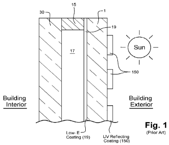
[0007] U.S. Patent No. 9,650,290 discloses an IG window
unit for reducing
bird collisions, as shown for example in prior art Fig. 1. The IG window unit
in Fig. 1
includes first glass substrate 1 and second glass substrate 30 that are spaced
apart
from one another at least by one or more peripheral seal(s) or spacer(s) 15.
The
spacer(s) 15, other spacer(s), and/or peripheral seal space the two substrates
1 and 30
apart from one another so that the substrates do not contact one another and
so that a
space or air gap 17 is defined therebetween. Air gap 17 may or may not be
filled with
gas such as argon. A solar management coating 19 (e.g., low-E coating) and a
UV
reflecting coating 150 are provided on the same glass substrate 1. The UV
reflecting
coating 150 is made up of glass/NbOx/SiOdNbOx/SiOJNbOx. The Nb0,, may be
replaced with TiOx. Unfortunately, it has been found that the UV reflecting
coating
150 does not provide particular good contrast ratio to bird (the difference
between
coated and uncoated areas of the glass) at large viewing angles such as 40-45
degrees.
In other words, when a bird approaches the window from an angle (e.g., 40-45
degrees from normal), the bird has a difficult time seeing the difference
between the
2
CA 03177414 2022- 10- 31
WO 2021/258082
PCT/ITS2021/041014
coated and uncoated areas, and thus has a difficult time realizing that a
window is
present. This leads to a large number of hard bird collisions with windows,
and thus
significant bird injuries.
[0008] In view of the above, it will be appreciated that
there exists a need in
the art for improved windows which can prevent or reduce bird collisions
therewith.
BRIEF SUMMARY OF THE INVENTION
[0009] In certain example embodiments of this invention, a
window is
designed to prevent or reduce bird collisions therewith. In certain example
embodiments, the window may comprise an insulating glass (IG) or other type of
window unit designed to prevent or reduce bird collisions therewith. The IG
window
unit includes at least first and second substrates (e.g., glass substrates)
spaced apart
from one another, wherein at least one of the substrates supports an
ultraviolet (UV)
reflecting coating for reflecting UV radiation so that birds are capable of
more easily
seeing the window. A third substrate (e.g., glass substrate) may optionally be
provided, and in scenarios where the third substrate is optionally provided at
least two
of the substrates may be laminated to one another via a polymer-based
laminating
film. The UV reflecting coating is preferably patterned so that it is not
provided
across the entirety of the IG window unit. In certain example embodiments of
this
invention, the UV reflecting coating is designed so as to be more visible to
birds at
high viewing angles (e.g., 30-45 degrees from normal), so that birds
approaching the
window at such high angles can more easily see the window and avoid hard
window
collisions. In other words, the UV reflecting coating is designed to have a
high
contrast ratio (higher visible difference between coated and uncoated areas of
the
glass) at such high viewing angles. By making the window more visible to birds
at
such angles, bird collisions and bird deaths can be reduced. Optionally, when
lamination is provided, provision of the laminated substrates in the IG window
can
further reduce bird collisions by providing an increased contrast ratio, and
improved
durability. The improved coatings of certain example embodiments of this case
may,
or may not, be used in conjunction with laminated embodiments herein.
3
CA 03177414 2022- 10- 31
WO 2021/258082
PCT/ITS2021/041014
[0010] By making the window more visible to birds at high
viewing angles
(e.g., 30-45 degrees from normal), hard bird collisions and bird deaths can be
reduced.
The particular UV reflecting coating(s) provided herein, and/or the provision
of
laminated substrates, is/are particularly advantageous for bird collision
windows,
because each of these increases the contrast ratio of the IG window unit
between areas
having the UV reflecting coating and areas not having the UV reflecting
coating, with
the improved coatings having a significant impact at higher viewing angles,
thereby
making the window more visible to birds and reducing the likelihood of bird
collisions.
[0011] In an example embodiment of this invention, there is
provided an IG
window unit for reducing bird collisions, comprising: a first glass substrate;
a second
glass substrate; wherein the first glass substrate is provided at an exterior
side of the
IG window unit so as to face an exterior of a building in which the IG window
unit is
to be mounted; a patterned UV reflecting coating provided on the first glass
substrate
and on an exterior surface of the IG window unit so as to face an exterior of
a building
in which the IG window unit is to be mounted; wherein the UV reflecting
coating
blocks at least 38% of UV radiation in at least a substantial part of a
wavelength range
from 330-380 nm; wherein the UV reflecting coating comprises, moving away from
the first glass substrate: a first high index transparent dielectric layer; a
first low index
transparent dielectric layer; a second high index transparent dielectric
layer; a second
low index transparent dielectric layer; and wherein the IG window unit, as
viewed
from the exterior thereof, has a UV reflectance of at least 30% at a
wavelength of 380
nm for both a viewing angle of 8 degrees and a viewing angle of 45 degrees
from
normal.
[0012] In an example embodiment, there is provided a coated
article (e.g., for
use in a window unit or spandrel) for reducing bird collisions, comprising: a
first glass
substrate; a patterned UV reflecting coating provided on the first glass
substrate;
wherein the UV reflecting coating blocks at least 38% of UV radiation in at
least a
substantial part of a wavelength range from 330-380 nm; wherein the UV
reflecting
coating comprises, moving away from the first glass substrate: a first high
index
transparent dielectric layer; a first low index transparent dielectric layer;
a second
4
CA 03177414 2022- 10- 31
WO 2021/258082
PCT/ITS2021/041014
high index transparent dielectric layer; a second low index transparent
dielectric layer;
and wherein the coated article, as viewed from an exterior thereof, has a UV
reflectance of at least 30% at a wavelength of 380 nm for both a viewing angle
of 8
degrees and a viewing angle of 45 degrees from normal.
BRIEF DESCRIPTION OF THE DRAWINGS
[0013] FIGURE 1 is a cross sectional view of an IG window
unit, which may
be used in certain example embodiments of this invention.
[0014] FIGURE 2 is a cross sectional view of an IG window
unit according to
an example embodiment of this invention.
[0015] FIGURE 3 is a cross sectional view of an IG window
unit according to
another example embodiment of this invention.
[0016] FIGURE 4 is a cross sectional view of a coated
article, including a UV
reflective coating, which may be used in conjunction with the structures of
any of
FIGS. 1-3 according to certain example embodiments of this invention.
[0017] FIGURE 5 is a cross sectional view of another coated
article, including
a UV reflective coating, which may be used in conjunction with the structures
of any
of FIGS. 1-3 according to certain example embodiments of this invention.
[0018] FIGURE 6 is a cross sectional view of another coated
article, including
a UV reflective coating, which may be used in conjunction with the structures
of any
of FIGS. 1-3 according to certain example embodiments of this invention.
[0019] FIGURE 7 is a graph plotting UV reflectance
(vertical axis, UV
reflectance %) of the coated article of Example 1 across a wide range of
wavelengths
(330-780 nm, horizontal axis), demonstrating that the coated article of this
example
has a high UV reflectance at both an 8 degree viewing angle (A plot) and a 45
viewing
angle, from the normal viewing angle.
[0020] FIGURE 8 is a graph plotting UV reflectance
(vertical axis, UV
reflectance %) of the coated article of Example 2 across a wide range of
wavelengths
(330-780 nm, horizontal axis), demonstrating that the coated article of this
example
CA 03177414 2022- 10- 31
WO 2021/258082
PCT/ITS2021/041014
has a high UV reflectance at both an 8 degree viewing angle (A plot) and a 45
viewing
angle, from the normal viewing angle.
[0021] FIGURE 9 is a graph plotting UV reflectance
(vertical axis, UV
reflectance %) of the coated article of Example 3 across a wide range of
wavelengths
(330-780 nm, horizontal axis), demonstrating that the coated article of this
example
has a high UV reflectance at both an 8 degree viewing angle (A plot) and a 45
viewing
angle, from the normal viewing angle.
[0022] FIGURE 10 is a graph plotting UV reflectance
(vertical axis, UV
reflectance %) of the coated article of Example 4 across a wide range of
wavelengths
(330-780 nm, horizontal axis), demonstrating that the coated article of this
example
has a high UV reflectance at both an 8 degree viewing angle (A plot) and a 45
viewing
angle, from the normal viewing angle.
DETAILED DESCRIPTION OF EXAMPLE EMBODIMENTS OF
THE INVENTION
[0023] Referring now more particularly to the accompanying
drawings in
which like reference numerals indicate like parts throughout the several
views.
[0024] The difference between color vision of a bird and
human is significant.
A bird's visual receptor may be around 370 nm which means that birds can
generally
see efficiently in the UV range, and in at least a portion of the blue visible
range.
Using this difference, it is possible to make a coating that efficiently
reflects UV
(making it visible to birds) while being substantially neutral/invisible to
human eyes.
Thus, the UV coating may be designed to have essentially the same or a similar
reflectance characteristic as bare glass, so as to be substantially invisible
to humans.
[0025] In certain example embodiments of this invention, a
window is
designed to prevent or reduce bird collisions therewith. In certain example
embodiments, the window may comprise an insulating glass (IG) window unit
designed to prevent or reduce bird collisions therewith. The IG window unit
includes
at least first (any of 1, 30 or 31 in any of Figs. 1-3) and second (another of
1, 30 or 31
6
CA 03177414 2022- 10- 31
WO 2021/258082
PCT/ITS2021/041014
in any of Figs. 1-3) substrates (e.g., glass substrates) spaced apart from one
another,
wherein at least one of the substrates supports an ultraviolet (UV) reflecting
coating
150 for reflecting UV radiation so that birds are capable of more easily
seeing the
window. A third (yet another of 1, 30 or 31 in any of Figs. 2-3)substrate
(e.g., glass
substrate) may optionally be provided, and in scenarios where the third
substrate is
optionally provided at least two of the substrates may be laminated to one
another via
a polymer-based laminating film 200 (e.g., of or including PVB, EVA, or SGP).
One
or more of the glass substrates may, or may not, be heat treated (e.g.,
thermally
tempered). The UV reflecting coating 150 is preferably patterned so that it is
not
provided across the entirety of the IG window unit, and may optionally be
provided
on surface #1 of the IG window unit so as to be exposed to atmosphere and be
at the
outermost part of the IG window unit. The "pattern" of the coating 150 on the
glass
substrate 1 may be in the form of substantially parallel stripes on the glass
substrate,
or may be any other suitable pattern such as a zig-zag pattern, a pattern of
dots, a
pattern of squares, a pattern of triangles, or any other suitable pattern.
[0026] In certain example embodiments of this invention,
the UV reflecting
coating 150 (e.g., see Figs. 4-10) is designed so as to be more visible to
birds at high
viewing angles (e.g., 30-45 degrees from normal), so that birds approaching
the
window at such high angles can more easily see the window and avoid hard
window
collisions. In other words, the UV reflecting coating 150 is designed to have
a high
contrast ratio (higher visible difference between coated and uncoated areas of
the
glass) at such high viewing angles. By making the window more visible to birds
at
such angles, bird collisions and bird deaths can be reduced. Optionally, when
lamination is provided via layer 200, provision of the laminated substrates in
the IG
window can further reduce bird collisions by providing an increased contrast
ratio,
and improved durability. Improved UV reflective coatings 150 (e.g., see Figs.
4-10)
may be used in any of window structures of Figs. 1-3 in various example
embodiments of this invention. Thus, the improved UV reflective coatings 150
of
certain example embodiments of this case may, or may, not be used in
conjunction
with laminated embodiments herein.
7
CA 03177414 2022- 10- 31
WO 2021/258082
PCT/ITS2021/041014
[0027] Thus, certain example embodiments make the UV
reflective coating
150 more visible to birds. The conventional five layer coatings of U.S. Patent
No.
9,650,290 (e.g., glass/NbOx/SiOx/NbOx/SiOx/Nb0.) have poor visibility to birds
at
angle. UV reflecting coatings are improved herein, so as to have contrast
ratio
(coated vs uncoated glass) which is higher at angle (e.g., 30-45 degrees from
normal)
for improved bird visibility (e.g., see Figs. 4-10), based on bird cone
sensitivity values
of representative birds. For instance, conventional coatings of U.S. Patent
No.
9,650,290 (e.g., glass/NbOx/SiOx/NbOx/SiOx/Nb0.) have a contrast ratio of 1.4
at a
45 degree viewing angle. In certain example embodiments of this case, the UV
reflecting coatings according to certain example embodiments of this invention
(e.g.,
see Figs. 4-10) are designed to have a higher reflective contract ratio (e.g.,
at least 1.6,
more preferably at least 1.7, even more preferably at least 1.8, and most
preferably at
least 1.9) for birds at a 45 degree viewing angle, and also optionally at low
viewing
angles such as about 3-8 degrees. This may be achieved, for example, with a
new UV
reflective coating 150 (e.g., see Figs. 4-10), which also has low visibility
to humans
so that it is also aesthetically pleasing to humans. In certain example
embodiments,
layer thicknesses and/or the number of layers of the UV reflective coating 150
may be
adjusted to achieve higher contrast ratios at angle and/or at normal.
[0028] By making the window more visible to birds at high
viewing angles
(e.g., 30-45 degrees from normal), hard bird collisions and bird deaths can be
reduced.
The particular UV reflecting coating(s) 150 provided herein, and/or the
provision of
laminated substrates, is/are particularly advantageous for bird collision
windows,
because each of these increases the contrast ratio of the IG window unit
between areas
having the UV reflecting coating 150 and areas not having the UV reflecting
coating,
with the improved coatings having a significant impact at higher viewing
angles,
thereby making the window more visible to birds and reducing the likelihood of
bird
collisions.
[0029] Referring to Fig. 1 for example, a UV reflective
coating 150 (e.g., see
Figs. 4-10) according to example embodiments of this invention may be provided
on
the exterior surface of glass substrate 1 in a patterned manner. Low-E coating
19 may
be provided on the other side of glass substrate 1, with air gap 17 (which may
be filled
8
CA 03177414 2022- 10- 31
WO 2021/258082
PCT/ITS2021/041014
with a gas such as argon) being provided between glass substrates 1 and 30 of
the IG
window unit.
[0030] In other example embodiments of this case, referring
to Figs. 2-3 for
example which are laminated embodiments, a pair of spaced apart substrates 30,
31
may be separated from one another by at least one seal and/or spacer 15. In
certain
example embodiments, there is provided a solar management coating (e.g., low-E
coating) 19 for blocking at least some infrared (IR) radiation and a UV
reflecting
blocking coating 150 (e.g., see Figs. 4-10) for reflecting UV radiation to
make the
window more visible to birds in order to reduce collisions. In certain example
embodiments, the low-E coating 19 may have an emissivity (Eõ) of no greater
than
0.10 and/or a sheet resistance (Rs) of no greater than 8 ohms/square. In
certain
example embodiments, the UV reflecting coating 150 may block at least 38%
(more
preferably at least 40%, more preferably at least 55%, even more preferably at
least
60%, and possibly at least 65%) of UV radiation in at least a substantial part
of the
range from 350 to 420 nm (or alternatively in at least a substantial part of
the range
from 330-400 nm). This increases the UV reflection of the window unit intended
for
commercial or residential applications in order to make such windows more
visible to
birds thereby preventing or reducing bird collisions. The use of such coatings
150
herein enhances the performance of the glass or window by increasing the UV
reflectance beyond the normal limits of raw uncoated plate glass. In certain
example
embodiments, the UV reflecting/blocking coating 150 is patterned (e.g., in a
grid
pattern or in a parallel striped pattern) on the window unit, as shown in
Figs. 1-3,
which can make it even more visible to birds to reduce bird collisions.
[0031] The IG window units of Figs. 1-3 preferably have a
visible
transmission of at least about 30%, more preferably at least about 50%, more
preferably of at least about 60%, and even more preferably of at least about
65% or at
least about 70%. However, patterned coating 150 on glass substrate 1 need not
be
used in 1G window units in all applications, and instead may be used in other
applications such as spandrel applications which are substantially opaque,
monolithic
window units, and laminated window units. For example, UV reflecting coating
150
can be provided on glass substrate 1 in a single or double sided laminated
window
9
CA 03177414 2022- 10- 31
WO 2021/258082
PCT/ITS2021/041014
unit where the UV reflecting coating 150 (patterned, or not patterned) is
provided on
one or both sides of the laminated window unit (e.g., for zoo application
where birds
can fly on either side of the window unit, but where humans and lions are on
their
respective sides). For example, monolithic coated articles having only the
coating
150 on a glass substrate 1 may have: (a) a visible transmission of at least
about 10%,
more preferably of at least about 50%, even more preferably of at least about
80%,
and sometimes of at least about 85%, (b) film side UV reflectance of at least
38%
(more preferably at least 40%, more preferably at least 55%, even more
preferably at
least 60%, and possibly at least 65%) in areas where the coating 150 is
present, and
(c) film side visible reflectance of less than about 25%, more preferably less
than
about 20%, and most preferably less than about 10%. Thus, the film side UV
reflectance may be at least about 4 times higher in the areas where coating
150 is
present on the glass 1 compared to areas where coating 150 is not present on
the glass
1 (more preferably at least about 5 times higher, even more preferably at
least about 8
times higher, and possibly at least 10 times higher).
[0032] In Figs. 2-3, the polymer based laminating film 17
preferably absorbs
UV, and may be of or include PVB, EVA, SOP, or the like. Thus, Figs. 2 and 3
differ
from each other mainly in that (i) the laminated structure is provided on the
inboard
side of the air gap17 and on the inboard side of the low-E coating 19 in Fig.
2, but is
provided on the outboard side of the air gap 17 and low-E coating 19 in Fig.
3, and (ii)
Fig. 3 provides for a structure allowing two single-coated-side glass
substrates 1 and
30 to be provided which improves production durability and processing so as to
reduce likelihood of coating damage during processing, manufacturing, and/or
shipping. With respect to point (ii), in Fig. 3 glass substrate 1 is only
coated on one
side with UV coating 150, and glass substrate 30 is only coated on one side
with low-
E coating 19, in the manufacturing process (laminating film 200 is an
interlayer for
laminating/adhering purposes and is not a film that is sputter-deposited or
otherwise
deposited onto a surface of a substrate). In contrast, the Fig. 2 embodiment
requires
that both sides of glass substrate 1 be coated, one side with the UV coating
150 and
the other side with the low-E coating, which can increase risk of damage
during
processing, shipping, and/or handling. The IG window units of Figs. 2-3 may
include
CA 03177414 2022- 10- 31
WO 2021/258082
PCT/ITS2021/041014
a solar management coating 19 (e.g., low-E coating) that is supported on an
inboard
side of glass substrate 1 (Fig. 2) or on an inboard side of glass substrate 30
(Fig. 3).
Low-E coating 19 includes one or more layers, although in many embodiments it
is a
multi-layer coating. Low-E coating 19 includes at least one IR reflecting
layer (e.g.,
based on silver or gold) sandwiched between at least first and second
dielectric layers.
Since one example function of low-E coating 19 is to block (i.e., reflect
and/or
absorb) certain amounts of 1R radiation and prevent the same from reaching the
building interior, the solar management coating 9 includes at least one IR
blocking
(i.e., IR reflecting and/or absorbing) layer. Example IR blocking layer(s)
which may
be present in coating 19 are of or include silver (Ag), nickel-chrome (NiCr),
gold
(Au), and/or any other suitable material that blocks significant amounts of IR
radiation. It will be appreciated by those skilled in the art that IR blocking
layer(s) of
low-E coating 19 need not block all IR radiation, but only need to block
significant
amounts thereof. In certain embodiments, each IR blocking layer of coating 19
is
provided between at least a pair of dielectric layers. Example dielectric
layers include
silicon nitride, titanium oxide, silicon oxynitride, tin oxide, and/or other
types of
metal-oxides and/or metal-nitrides. In certain embodiments, in addition to
being
between a pair of dielectric layers, each IR blocking layer may also be
provided
between a pair of contact layers of or including a material such as an oxide
and/or
nitride of nickel-chrome or any other suitable material. Example low-E
coatings 19
are described in U.S. Patent Nos. 7,267,879, 6,576,349, 7,217,461, 7,153,579,
5,800,933, 5,837,108, 5,557,462, 6,014,872, 5,514,476, 5,935,702, 4,965,121,
5,563,734, 6,030,671, 4,898,790, 5,902,505, 3,682,528, all of which are hereby
incorporated herein by reference. In certain example embodiments, before
and/or
after optional heat treatment (e.g., thermal tempering and/or heat bending),
the low-E
coating 19 may have a sheet resistance (Rs) of no greater than 8 ohms/square,
more
preferably no greater than 6 ohms/square, and most preferably no greater than
4
ohms/square. In certain embodiments, the low-E coating 19 may have an
emissivity
(En) after heat treatment of no greater than 0.10, more preferably no greater
than 0.07,
and even more preferably no greater than 0.05 (before and/or after optional
heat
treatment). Of course, solar management coatings 19 herein are not limited to
these
particular coatings, and any other suitable solar management coatings capable
of
11
CA 03177414 2022- 10- 31
WO 2021/258082
PCT/US2021/041014
blocking amounts of IR radiation may instead be used. Solar management
coatings
19 herein may be deposited on substrate(s) 1 and/or 30 in any suitable manner,
including but not limited to sputtering, vapor deposition, and/or any other
suitable
technique.
[0033] Referring to Figs. 1-3, the IG window units include
UV reflecting
coating 150 for reflecting significant amounts of UV radiation thereby making
the
window more visible to birds. Coatings 150 may be sputter-deposited in example
embodiments of this invention. UV reflecting coating 150 may be, for purposes
of
example and without limitation, any of the UV reflecting coatings illustrated
in Figs.
4-6. This increases the UV reflection of the window unit in order to make such
windows more visible to birds thereby preventing or reducing bird collisions.
The use
of such coatings 150 herein enhances the performance of the glass or window by
increasing the UV reflectance beyond the normal limits of raw uncoated plate
glass.
In certain example embodiments, the UV reflecting coating 150 is in direct
contact
with the glass substrate 1 on the exterior surface thereof, and is not part of
a low-E
coating 19. In particular, there are no IR reflecting layers (e.g., silver
based, gold
based, NiCr, or IR reflecting TCO-based layers) in coating 150, and there are
no IR
reflecting layers on the side of the substrate 1 on which the coating 150 is
provided.
Instead, any low-E coatings (e.g., see low-E coating 19) may be provided on
the other
side of substrate 1 from coating 150 or alternatively on substrate 30. In
certain
example embodiments, the UV reflecting coating 150 may block (e.g., absorbs
and/or
reflects) at least 38% (more preferably at least 40%, more preferably at least
50% or
55%, even more preferably at least 60%, and possibly at least 65%) of UV
radiation
in at least a substantial part of the range from 350 to 420 nm (or
alternatively in at
least a substantial part of the range from 330-400 nm, or alternatively in at
least a
substantial part of the range from 330-380 nm).
[0034] The UV reflecting coating 150 may be patterned
(e.g., in the shape of a
grid or in substantially parallel or non-parallel stripes, crossing stripes,
or other
shapes/forms) on the surface of substrate 1 as shown in Figs. 1-3, or
alternatively may
be provided continuously across substantially the entire surface of substrate
1 in other
embodiments. The patterned shape of coating 150 may be formed as follows, for
12
CA 03177414 2022- 10- 31
WO 2021/258082
PCT/ITS2021/041014
purposes of example. A pattern (not shown) is provided on the surface of
substrate 1
prior to the coating 150 being formed, with the pattern being located in areas
which
are ultimately to be free of coating 150. After the pattern is formed, a
coating 150 is
continuously formed across the entire or substantially the entire surface of
substrate 1
over the pattern. The pattern can then be removed (along with the portions of
coating
150 located directly over it) in order to create a patterned coating 150, so
that the
coating 150 remains on only the portions of the substrate where the original
pattern
was not deposited. Thus, a patterned coating 150 can be formed in such a
manner in
example embodiments of this invention. The remaining patterned coating 150 is
substantially invisible to human eyes, but is visible to bird eyes as
explained above.
[0035] Figs. 7-10 illustrate film side reflection from
certain example
embodiments of this invention across a range of wavelengths, including UV
wavelengths. The high UV reflection at different viewing angles at the left
sides of
Figs. 7-10, for the coated articles of various examples of this invention,
demonstrates
that a high reflective contrast ratio CR(RF) will be realized for UV and
possibly
certain blue wavelengths, thereby rendering the windows more easily to be seen
by
bird at various viewing angles, where RF is calculated from a bird's
perspective.
( if ¨ _____________________________ ¨
[0036]
[0037] Thus, the contrast ratio of the IG unit has
surprisingly been found to be
significantly higher at the combination of low and high viewing angles,
compared to
conventional coatings, and will thus be more visible to birds at high
viewing/approach
angles and thus realize less bird collisions.
[0038] Figs. 4-6 are cross sectional views of various UV
reflecting coatings
150 that may be used on substrate 1 in the IG window unit of any of Figs. 1-3
in
example embodiments of this invention. Glass substrate 1 may be soda-lime-
silica
based glass or any other suitable type of glass, and may be from about 1-10 mm
thick,
more preferably from about 2-6 mm thick, in example embodiments of this
invention.
[0039] In the Fig. 4 embodiment, UV reflecting coating 150
includes high
index transparent dielectric layers 2, 4, 6 and 8. High index transparent
dielectric
layers 2, 4, 6 and 8 may be of or include an oxide of Ti (e.g., TiOx). One,
two, three,
13
CA 03177414 2022- 10- 31
WO 2021/258082
PCT/ITS2021/041014
or all four of high index transparent dielectric layers 2, 4, 6 and 8 may be
oxygen-rich,
so that for example the oxide of Ti may be represented by TiOx where x is at
least
2.01, more preferably from 2.01-2.25, even more preferably from 2.02 to 2.20,
and
still more preferably from 2.03 to 2.20. It is also possible that the oxide of
Ti may be
TiO2 in one or more of layers 2, 4, 6 and/or 8.
[0040] In certain example embodiments, one, two, three, or
all four of high
index transparent dielectric layers 2, 4, 6 and 8 may have, at a wavelength of
360 nm,
a "k" value of less than 0.025, more preferably less than 0.024, and most
preferably
less than 0.023, and an "n" value of at least 2.90, more preferably at least
2.91, and
most preferably at least 2.95. In certain example embodiments, one, two,
three, or all
four of high index transparent dielectric layers 2, 4, 6 and 8 may have, at a
wavelength of 380 nm, a "k" value of less than 0.0001, and an "n" value of at
least
2.75. It has been surprisingly and unexpectedly found that designing one or
more of
the high index layers to have such n and k values, such as via the oxygen-rich
technique described above, cuts down on UV absorption and thus allows UV
reflection to be increased including at high viewing angles, so as to render
windows
more visible to birds at high viewing angles such as 45 degrees.
In certain example embodiments, one, two, three, or all four of high index
transparent dielectric layers 2, 4, 6 and 8 may be of or include an oxide of
Ti that is
doped with at least one other element such as Zr, Ce, Nb, or the like. For
example,
one, two, three, or all four of high index transparent dielectric layers 2, 4,
6 and 8 may
be of or include an oxide of Ti that is doped so that a meal content of the
layer(s) is
from about 1-25% Zr and/or Ce, more preferably from about 2-20% Zr and/or Ce,
even more preferably from about 5-15% Zr and/or Ce, with an example being a
metal
content of the layer being about 10% Zr and/or Ce (atomic %). For example,
one,
two, three, or all four of high index transparent dielectric layers 2, 4, 6
and 8 may be
of or include an oxide of Ti doped with Zr (e.g., TiZrOx), which may be oxygen
rich
as described above. For example, it has been surprisingly found that in this
particular
coating the addition of the Zr (and/or oxide thereof) to the TiOx helps reduce
haze and
delamination, and also with manufacturing costs. For example and without
limitation,
any or all of layers 2, 4, 6 and/or 8 may be sputter-deposited using TiZrOx
targets
14
CA 03177414 2022- 10- 31
WO 2021/258082
PCT/ITS2021/041014
made of TiOx (where x may be from 1.5 to 2.0 for example) and ZrO2, where the
sputtering may be performed in an atmosphere including at least oxygen gas
sufficient
for the oxygen-rich feature if desired.
[0041] Alternatively, high index transparent dielectric
layer 2 for example
may be of or including an oxide of Ti (e.g., TiO2), an oxide of Nb, or an
oxide of Ti
and Zr (e.g., TiZrOx) which may be oxygen rich, for example.
[0042] Low index transparent dielectric layers 3, 5, and 7
may be of or include
silicon oxide (e.g., SiO2) which may or may not be doped with other element(s)
such
as aluminum and/or nitrogen. In certain example embodiments, any of the
silicon
oxide layers 3, 5 and/or 7 may be doped with other material such as from about
1-8%
aluminum and/or from about 1-10% nitrogen. One or more of layers 2, 4, 6
and/or 8
may also be doped with other material in certain example instances. Optional
overcoat 9, of or including a material such as an oxide of zirconium (e.g.,
ZrO2), may
also be provided. Other layer(s) may be added to the Fig. 4 embodiment, and it
is also
possible for one or more layers to be removed from the Fig. 4 embodiment. Each
of
layers 2-9 is considered "transparent" to visible light because each of these
layers,
standing alone, is substantially transparent to visible light (e.g., at least
about 50%
transparent, more preferably at least about 60% or 70% transparent to visible
light).
100431 The "oxygen rich" feature of one, two, three, or all
four of high index
layers 2, 4, 6 and/or 8 relates to an oxygen-rich stoichiometry of the final
layer. This
is done in order to lower absorption, and increase reflection, in the UV
(ultraviolet).
For instance, stoichiometric TiO2 is prone to having high absorption in the
UV, and
this high absorption decreases reflection. Thus, in order to provide high UV
reflection at both normal and across a wide range of viewing angles, in
certain
example embodiments, of this invention, one, two, three, or all four of high
index
layers 2, 4, 6 and/or 8 are provided with an oxygen-rich stoichiometry. The
desirable
results of this can be seen in the UV reflectance graphs, depicted in Figs. 7-
10.
[0044] The Fig. 5 embodiment is the same as the Fig. 4
embodiment described
herein, except that layers 6-8 have been removed from the Fig. 4 embodiment.
See
the description above of the layers 2-5 and 9 of the Fig. 5 embodiment.
CA 03177414 2022- 10- 31
WO 2021/258082
PCT/ITS2021/041014
[0045] The Fig. 6 embodiment is the same as the Fig. 4
embodiment described
herein, except that layers 7-8 have been removed from the Fig. 4 embodiment.
See
the description above of the layers 2-6 and 9 of the Fig. 5 embodiment. It is
also
noted that in the Fig. 6 embodiment layer 6' may be omitted, or layer 6' may
be an
oxide of Ti and Zr (e.g., TiZr0),), which may be oxygen rich, or alternatively
may be
of or include a different material such as an oxide of Ti (e.g., TiO2).
[0046] High index transparent dielectric layers 2, 4, 6 (or
6') and 8 may have a
refractive index (n) of from about 2.15 to 2.7, more preferably from about 2.3
to 2.6
(at 550 nm). Low index transparent dielectric layers 3, 5 and 7 of or
including silicon
oxide may have a refractive index (n) of from about 1.4 to 1.7, more
preferably from
about 1.4 to 1.6, and most preferably from about 1.45 to 1.55 (all refractive
index n
values herein are measured at 550 nm). Transparent dielectric layers 2-9 are
preferably deposited by sputtering in example embodiments of this invention.
[0047] In certain example embodiments of the Fig. 4-6
embodiments of this
invention: transparent dielectric layer 2 may be from about 4-25 nm thick,
more
preferably from about 8-17 nm thick, and most preferably from about 10-15 nm
thick;
transparent dielectric layer 3 of or including silicon oxide may be from about
30-100
nm thick, more preferably from about 50-70 nm thick, even more preferably from
about 55-63 nm thick; transparent dielectric layer 4 may be from about 20-60
nm
thick, more preferably from about 30-40 nm thick, even more preferably from
about
32-36 nm thick; transparent dielectric layer 5 of or including silicon oxide
may be
from about 20-130 nm thick, more preferably from about 25-100 nm thick, even
more
preferably from about 30-60 nm thick; transparent dielectric layer 6 (or 6')
may be
from about 20-60 nm thick, more preferably from about 25-45 nm thick, even
more
preferably from about 30-40 nm thick; transparent dielectric layer 7 of or
including
silicon oxide may be from about 30-100 nm thick, more preferably from about 50-
80
nm thick, even more preferably from about 60-70 nm thick; transparent
dielectric
layer 8 may be from about 4-60 nm thick, more preferably from about 5-30 nm
thick,
even more preferably from about 10-15 nm thick; and optional transparent
overcoat
protective dielectric layer 9 of or including zirconium oxide may be from
about 5-60
nm thick, more preferably from about 5-30 nm thick, even more preferably from
16
CA 03177414 2022- 10- 31
WO 2021/258082
PCT/ITS2021/041014
about 5-20 nm thick, with an example thickness being about 10-11 nm. To
realize the
desired UV reflectance and visible transmission values herein, layer 4 is
preferably
substantially thicker than layer 2. For example, in certain example
embodiments,
layer 4 is at least about 10 nm thicker (more preferably at least about 15 nm
thicker)
than layer 2. Moreover, to realize the desired UV reflectance and visible
transmission
values herein, layer 6 is preferably substantially thicker than layer 8. For
example, in
certain example embodiments, layer 6 is at least about 10 nm thicker (more
preferably
at least about 15 nm thicker) than layer 8.
EXAMPLES
[0048] The following examples are provided for purposes of
example, with
respect to implementing certain example non-limiting embodiments of this
invention.
[0049] Example 1 is based on the coating 150 of Fig. 4. See
Figs. 4 and 7.
For bird deterrence, it is desirable for UV reflective coating 150 to be
visible to birds
during flight. Coating 150 is designed to maintain good deterrence at least up
to a 45-
degree angle from normal incidence as birds fly in all directions. For angles
greater
than 45 degrees, one tip of the wing(s) may contact the glass on approach
which can
alert the bird of its presence before a hard collision occurs. With that mind,
all
designs and measurements herein check the spectral response at two angles: at
a
typical 8-degree viewing angle and also at a viewing angle of 45 degrees. The
coating
of Example 1 is set forth in the table below.
Coating 150 of Example 1
Material Layer thickness (nm)
Glass
TiO2 or TiZrOx 02 rich 14.0
Si02 55.6
TiZrOx 02 rich 34.9
5'02 43.1
TiZrOx 02 rich 31.6
Si02 66.9
TiZrOx 02 rich 10.1
Zr02 10.0
17
CA 03177414 2022- 10- 31
WO 2021/258082
PCT/ITS2021/041014
The following optical results were obtained from the coating of Example 1,
where Rf
refers to film side visible reflectance, T refers to visible transmission, and
Rg refers to
glass side visible reflectance.
a* b*
Rf 8 degree 9.1 1.5 2.0
10.8
Rf 45 degree 0.3 1.9
T 2 degree 88.1 1.9 -0.1
Rg 8 degree 9.1 1.5 1.9
This design has a slightly higher reflection in the visible than naked glass
(9.1% vs.
8.3%), but the color remains fairly neutral and the coating nearly invisible
to the
human eye.
[0050] With respect to UV wavelengths visible to birds,
Fig. 7 is a graph
plotting film side UV reflectance (vertical axis, UV reflectance %) of the
coated
article of Example 1 across a wide range of wavelengths (330-780 nm,
horizontal
axis). As shown in Fig. 7, it has surprisingly and unexpectedly been found
that the
layer stack of Example 1 provides for a coated article having a high film side
UV
reflectance at both an 8 degree viewing angle (A plot) and a 45 viewing angle.
Not
only is the UV reflection high at substantially normal incidence (8 degrees),
it remains
significant at 45 degrees. This makes the coating highly visible to birds
across a wide
range of viewing angles.
[0051] Example 2 is also based on the coating 150 of Fig.
4. See Figs. 4 and
8. The coating of Example 2 is set forth in the table below.
Coating 150 of Example 2: Neutral Light Blue
Material Layer Thickness
(nnn)
Glass n/a
TiO2 or TiZrOx 02 rich 13.5
Si02 58.0
TiZrOx 02 rich 35.1
Si02 39.4
TiZrOx 02 rich 35.6
18
CA 03177414 2022- 10- 31
WO 2021/258082
PCT/ITS2021/041014
Si02 60.2
TiZrOx 02 rich 12.0
Zr02 11.0
[0052] Example 2 has been found to have higher UV
reflection than Example
1. The color along with greater UV reflection of Example 2 makes it more
visible to
birds, while the soft blue (note the b* below) adds a cosmetic value for human
customers who want to show the coating for human aesthetic purposes. The
coating
150 of Example remains substantially invisible to humans, based on the optical
data
for Example 2 below.
a* b*
Rf 8 degree 11.7 2.6 -9.1
Rf 45 degree 12.6 -1.3 -0.7
T 2 degree 87.3 -1.64 2.91
Rg 8 degree 11.2 2.5 -9.0
[0053] With respect to UV wavelengths visible to birds,
Fig. 8 is a graph
plotting film side UV reflectance (vertical axis, UV reflectance %) of the
coated
article of Example 2 across a wide range of wavelengths (330-780 nm,
horizontal
axis). As shown in Fig. 8, it has surprisingly and unexpectedly been found
that the
layer stack of Example 2 provides for a coated article having a high film side
UV
reflectance at both an 8 degree viewing angle (A plot) and a 45 viewing angle.
Not
only is the UV reflection high at substantially normal incidence (8 degrees),
it remains
significant at 45 degrees. This makes the coating highly visible to birds
across a wide
range of viewing angles.
[0054] In certain example embodiments, the coating 150 is
designed so that
the window when viewed form the film side thereof has a film side reflective
b* color
value of from -7 to -30 (more preferably from -10 to -30) in order to provide
blue
color visible to birds (111. C, 2 Obs., or Rf at the 8 degree viewing angle),
to still
further reduce bird collisions.
[0055] Example 3 is also based on the coating 150 of Fig.
4. See Figs. 4 and
9. The coating of Example 3 is set forth in the table below.
19
CA 03177414 2022- 10- 31
WO 2021/258082
PCT/ITS2021/041014
Coating 150 of Example 3: Blue XT
Material
Layer Thickness (nm)
Glass n/a
TiO2 or TiZrOx 02 rich 10.8
Si02 62.5
TiZrOx 02 rich 32.2
SiO2 34.5
TiZrOx 02 rich 39.6
Si02 61.7
TiZrOx 02 rich 14.7
Zr02 11.0
Example 3 is excellent for bird deterrence of all UV designs, and it remains
practically invisible in transmission to the naked eye of humans in normal
viewing
conditions. The blue color of Example 3 is more intense than Example 2 (see b*
values), but the visible reflection for humans is still fairly low at 11.6%
(glass is
8.3%), as shown by the optical data for Example 3 as follows.
a* b*
Rf 8 degree 11.6 -0.8 -
16.3
Rf 45 degree 12.6 -2.1 -
11.6
T 2 degree 87.0 -0.6
5.0
Rg 8 degree 11.5 -1.0 -
15.8
[0056] With respect to UV wavelengths visible to birds,
Fig. 9 is a graph
plotting film side UV reflectance (vertical axis, UV reflectance %) of the
coated
article of Example 3 across a wide range of wavelengths (330-780 nm,
horizontal
axis). As shown in Fig. 9, it has surprisingly and unexpectedly been found
that the
layer stack of Example 3 provides for a coated article having a high film side
UV
reflectance at both an 8 degree viewing angle (A plot) and a 45 viewing angle.
Not
only is the UV reflection high at substantially normal incidence (8 degrees),
it remains
significant at 45 degrees. This makes the coating highly visible to birds
across a wide
range of viewing angles. The UV reflection is the greatest with a blue color
that
CA 03177414 2022- 10- 31
WO 2021/258082
PCT/ITS2021/041014
remains at angle (e.g., 45 degrees) due to the advantageous design which
allows a
bump in the 430-500 nm visible range while maintaining a low reflection in the
higher
visible wavelengths. Moreover, the continuously decreasing slope towards the
near
IR prevents/reduces the coating from turning red at any reasonable angle of
viewing.
[0057] Example 4 is based on the coating 150 of Fig. 5. See
Figs. 5 and 10.
The coating of Example 4 is set forth in the table below.
Coating 150 of Example 4: 5L Blue Ultra
Material Layer Thickness
(nm)
Glass n/a
TiO2 or TiZrOx 02 rich 23.5
Si02 60.9
TiZrOx 02 rich 33.6
Si02 59.0
Zr02 11.3
Example 4 is excellent for bird deterrence, and needs only five layers. The
coating
remains practically invisible to the naked eye of humans in transmission in
normal
viewing conditions, the blue color is intense, but the reflection is still
fairly low at
10.6% (glass is 8.3%), as shown in the optical data for Example 4 below.
a*
b*
Rf 8 degree 10.6 0.1 -
14.1
Rf 45 degree 11.7 -3.3 -
10.2
T 2 degree 88.5 -1.4
3.7
Rg 8 degree 9.8 0.0 -
13.4
[0058] With respect to UV wavelengths visible to birds,
Fig. 10 is a graph
plotting film side UV reflectance (vertical axis. UV reflectance %) of the
coated
article of Example 4 across a wide range of wavelengths (330-780 nm,
horizontal
axis). As shown in Fig. 10, it has surprisingly and unexpectedly been found
that the
layer stack of Example 4 provides for a coated article having a high film side
UV
reflectance at both an 8 degree viewing angle (A plot) and a 45 viewing angle.
Not
only is the UV reflection high at substantially normal incidence (8 degrees),
it remains
21
CA 03177414 2022- 10- 31
WO 2021/258082
PCT/ITS2021/041014
significant at 45 degrees. This makes the coating highly visible to birds
across a wide
range of viewing angles. The UV reflection is excellent, and the coating
increases its
reflection in the 430-500 nm range at angle while maintaining a low reflection
in
higher visible wavelengths.
[0059] Example 5 is based on the coating 150 of Fig. 5. See
Fig. 5. The
coating of Example 5 is set forth in the table below.
Coating 150 of Example 5: 5L Blue Baseline Alternate
Material Layer Thicknesses
(nm)
Glass n/a
TiO2 or TiZrOx 02 rich 22.6
Si02 52
TiZrOx 02 rich 36
5102 57
TiO2 or TiZrOx 02 rich 4
Zr02 7
[0060] Advantageously, the color shift at angle is nearly
non-existent (note
below the similar a* and b* film side reflective values between the 8 and 45
degree
viewing angles), so as to be aesthetically pleasing for humans. The UV
reflection
across the range of viewing angles is good as well.
RY a*
b*
Rf 8 degree 11.0 -3.0
-8.8
Rf 45 degree 12.2 -3.3
-9.2
T 2 degree 87.5 -0.8
2.3
Rg 8 degree 10.9 -2.9
-8.4
[0061] It can
be seen in Figs. 7-10 that in certain example preferred
embodiments of this invention the 1G window unit, as viewed from the exterior
thereof, has a UV reflectance of at least 30% (more preferably at least 40%,
and most
preferably of at least 50%, and sometime at least 60%) at a wavelength of 380
nm for
both a viewing angle of 8 degrees and a viewing angle of 45 degrees from
normal. It
can also be seen that the IG window unit, as viewed from the exterior thereof,
has a
UV reflectance at a wavelength of 380 nm that does not vary by more than 30%
(more
22
CA 03177414 2022- 10- 31
WO 2021/258082
PCT/ITS2021/041014
preferably by not more than 20%) between the viewing angle of 8 degrees and
the
viewing angle of 45 degrees.
[0062] In an example embodiment of this invention, there is
provided an IG
window unit for reducing bird collisions, comprising: a first glass substrate;
a second
glass substrate; wherein the first glass substrate is provided at an exterior
side of the
IG window unit so as to face an exterior of a building in which the IG window
unit is
to be mounted; a patterned UV reflecting coating provided on the first glass
substrate
and on an exterior surface of the IG window unit so as to face an exterior of
a building
in which the IG window unit is to be mounted; wherein the UV reflecting
coating
blocks at least 38% of UV radiation in at least a substantial part of a
wavelength range
from 330-380 nm; wherein the UV reflecting coating comprises, moving away from
the first glass substrate: a first high index transparent dielectric layer; a
first low index
transparent dielectric layer; a second high index transparent dielectric
layer; a second
low index transparent dielectric layer; and wherein the IG window unit, as
viewed
from the exterior thereof, has a UV reflectance of at least 30% at a
wavelength of 380
nm for both a viewing angle of 8 degrees and a viewing angle of 45 degrees
from
normal.
[0063] The IG window unit of the immediately preceding
paragraph, as
viewed from the exterior thereof, may have a UV reflectance of at least 40% at
a
wavelength of 380 nm for both a viewing angle of 8 degrees and a viewing angle
of
45 degrees from normal, more preferably a UV reflectance of at least 50% at a
wavelength of 380 nm for both a viewing angle of 8 degrees and a viewing angle
of
45 degrees from normal, and possibly a UV reflectance of at least 60% at a
wavelength of 380 nm for both a viewing angle of 8 degrees and a viewing angle
of
45 degrees from normal.
[0064] The IG window unit of any of the preceding two
paragraphs, as viewed
from the exterior thereof, may have a UV reflectance at a wavelength of 380 nm
that
does not vary by more than 30% between the viewing angle of 8 degrees and the
viewing angle of 45 degrees, more preferably a UV reflectance at a wavelength
of 380
nm that does not vary by more than 20% between the viewing angle of 8 degrees
and
the viewing angle of 45 degrees.
23
CA 03177414 2022- 10- 31
WO 2021/258082
PCT/ITS2021/041014
[0065] In the IG window unit of any of the preceding three
paragraphs, the
UV reflecting coating may block (absorb and/or reflect) at least 50% of UV
radiation
in at least a substantial part of a wavelength range from 330-380 nm.
[0066] In the IG window unit of any of the preceding four
paragraphs, the first
and second high index layers may have a refractive index of from 2.15 to 2.7
(at 550
nm), more preferably a refractive index of from 2.3 to 2.6 (at 550 nm).
[0067] In the IG window unit of any of the preceding five
paragraphs, the
first and second low index layers may have a refractive index (n) of from 1.4
to 1.7 (at
550 nm).
[0068] In the IG window unit of any of the preceding six
paragraphs, the first
and second low index layers may comprise an oxide of silicon, and may
optionally
further comprise nitrogen such that the first and second low index layers may
each
comprise SiO2, silicon oxynitride, and may be doped with Al or the like.
[0069] In the TO window unit of any of the preceding seven
paragraphs, the
first and/or second high index layers may comprise an oxide of Ti and Zr,
which may
be oxygen rich, and/or may comprise TiOx where x is at least 2.01, more
preferably
from 2.02-2.20.
[0070] In the IG window unit of any of the preceding eight
paragraphs, a low-
E coating may be provided on a side of the first substrate opposite the side
at which
the UV reflecting coating is provided.
[0071] In the IG window unit of any of the preceding nine
paragraphs, the UV
reflecting coating does not contain any IR reflecting layer based on Ag or Au
in
certain example embodiments.
[0072] The IG window unit of any of the preceding ten
paragraphs may
further comprise a third glass substrate, wherein the second glass substrate
may be
provided between at least the first and third glass substrates; wherein the
third glass
substrate may be provided at an interior side of the IG window unit so as to
face an
interior of a building in which the IG window unit is to be mounted; wherein
the
second glass substrate may be laminated via a polymer inclusive laminating
film to
either the first glass substrate or the third glass substrate; wherein the
first glass
24
CA 03177414 2022- 10- 31
WO 2021/258082
PCT/ITS2021/041014
substrate may be located between the patterned UV reflecting coating and the
polymer
inclusive laminating film.
[0073] The IG window unit of any of the preceding eleven
paragraphs may
have a visible transmission of at least about 30%.
[0074] In the IG window unit of any of the preceding twelve
paragraphs, the
UV reflecting coating may directly contact the first glass substrate.
[0075] In the IG window unit of any of the preceding
thirteen paragraphs, the
patterned UV reflecting coating may causes the IG window unit to have a
contrast
ratio of at least 1.6 (more preferably at least 1.7, and even more preferably
at least 1.8
or 1.9) at the 45 degree viewing angle, at the wavelength of 380 nm.
[0076] The IG window unit of any of the preceding fourteen
paragraphs may
further include a third high index transparent dielectric layer provided on
the first
glass substrate over at least the second low index layer, and a third low
index
transparent dielectric layer provided on the first glass substrate over at
least the third
high index layer. A fourth high index transparent dielectric layer may also be
provided over the third low index layer. At least two of the first, second,
and third
high index layers may comprise an oxide of Ti and Zr.
[0077] In the IG window unit of any of the preceding
fifteen paragraphs, one,
two, three, or four of the high index layers may have an oxygen-rich
stoichiometry.
[0078] The IG window unit of any of the preceding sixteen
paragraphs may
further include an overcoat comprising an oxide of zirconium.
[0079] The 1G window unit of any of the preceding sixteen
paragraphs, as
viewed from the exterior, may have a film side reflective b* color value of
from -7 to
-30 (Ill. C, 2), more preferably from -10 to -30, in order to provide blue
color visible
to birds for reducing bird collisions.
[0080] In the IG window unit of any of the preceding
seventeen paragraphs,
one, two, three, or more of the high index layers may have an oxygen-rich
stoichiometry.
CA 03177414 2022- 10- 31
WO 2021/258082
PCT/ITS2021/041014
[0081] In the IG window unit of any of the preceding
eighteen paragraphs, at
least one of the high index layers may comprises an oxide of Ti, that is doped
with
from about 1-20% (atomic %) Zr, Ce, and/or Nb with respect to metal content of
the
layer.
[0082] In the IG window unit of any of the preceding
nineteen paragraphs, at
least one of the high index layers may have an oxygen rich stoichiometry and
comprise an oxide of Ti, that is doped with from about 1-20% (atomic %) Zr
with
respect to metal content of the layer.
[0083] In an example embodiment, there is provided a coated
article (e.g., for
use in a window unit or spandrel) for reducing bird collisions, comprising: a
first glass
substrate; a patterned UV reflecting coating provided on the first glass
substrate;
wherein the UV reflecting coating blocks at least 38% of UV radiation in at
least a
substantial part of a wavelength range from 330-380 nm; wherein the UV
reflecting
coating comprises, moving away from the first glass substrate: a first high
index
transparent dielectric layer; a first low index transparent dielectric layer;
a second
high index transparent dielectric layer; a second low index transparent
dielectric layer;
and wherein the coated article, as viewed from an exterior thereof, has a UV
reflectance of at least 30% at a wavelength of 380 nm for both a viewing angle
of 8
degrees and a viewing angle of 45 degrees from normal.
[0084] The coated article of the immediately preceding
paragraph may have,
as viewed from the exterior thereof, a UV reflectance of at least 40% (more
preferably
of at least 50% or at least 60%) at a wavelength of 380 nm for both a viewing
angle of
8 degrees and a viewing angle of 45 degrees from normal.
[0085] The coated article of any of the preceding two
paragraphs may have, as
viewed from the exterior thereof, a UV reflectance at a wavelength of 380 nm
that
does not vary by more than 30% between the viewing angle of 8 degrees and the
viewing angle of 45 degrees.
[0086] In the coated article of any of the preceding three
paragraphs, the first
and/or second high index layers may have a refractive index of from 2.15 to
2.7, more
26
CA 03177414 2022- 10- 31
WO 2021/258082
PCT/ITS2021/041014
preferably from 2.3-2.6 (at 550 nm), and/or the first and second low index
layers may
have a refractive index (n) of from 1.4 to 1.7 (at 550 nm).
[0087] In the coated article of any of the preceding four
paragraphs, at least
one of the first and second high index layers may comprise an oxide of TiOx
where x
is at least 2.01 (so as to be oxygen rich).
[0088] The coated article of any of the preceding five
paragraphs may, as
viewed from the exterior, have a film side reflective b* color value of from -
7 to -30
(more preferably -10 to -30)(111. C, 2) in order to provide blue color visible
to birds for
reducing bird collisions.
[0089] In the coated article of any of the preceding six
paragraphs. the UV
reflecting coating may further comprises a third high index transparent
dielectric layer
provided on the first glass substrate over at least the second low index
layer, and/or a
third low index transparent dielectric layer provided on the first glass
substrate over at
least the third high index layer.
[0090] In the coated article of any of the preceding seven
paragraphs, at least
one of the first and second high index layers may comprise an oxide of Ti.
that is
doped with from about 1-20% (atomic %) Zr, Ce, and/or Nb with respect to metal
content of the layer. For example, at least one of the first and second high
index
layers may have an oxygen rich stoichiometry and comprises an oxide of Ti,
that is
doped with from about 1-20% (atomic %) Zr with respect to metal content of the
layer.
[0091] While the invention has been described in connection
with what is
presently considered to be the most practical and preferred embodiment, it is
to be
understood that the invention is not to be limited to the disclosed
embodiment, but on
the contrary, is intended to cover various modifications and equivalent
arrangements
included within the spirit and scope of the appended claims.
27
CA 03177414 2022- 10- 31