Note: Descriptions are shown in the official language in which they were submitted.
WO 2021/253061
PCT/AT2020/060248
1
Method for manufacturing an assembly for a spark plug and spark plug
The present invention concerns a method for manufacturing an assembly of a
center pin
and a middle electrode carrier or a middle electrode, respectively, for a
spark plug with
the features of the preamble of claim 1, a method for manufacturing a spark
plug, an
assembly of a center pin and a middle electrode carrier for a spark plug with
the
features of the preamble of claim 15 and a spark plug with such an assembly.
Spark plugs are known in various embodiments from the state of the art. Due do
the
efforts of improved life time requirements, the requirements regarding gas
tightness and
temperature management, i.e. enabling proper heat transfer between the spark
plugs
on the one hand and the cylinder head or the spark plug sleeves on the other
hand,
became more important.
Known spark plugs have a middle electrode which referring to a longitudinal
axis of the
spark plug is arranged centrally and at least one mass electrode radially
distanced from
said middle electrode. An ignition gap is formed between abutting areas
(ignition areas)
of the middle electrode and the at least one mass electrode.
It is known to form the middle electrode in at least two parts, wherein the
ignition area is
formed by a body of precious metal arranged on a middle electrode carrier. The
respective body of precious metal is connected by a welded joint to the mass
electrode
carrier and the middle electrode carrier, respectively. Such a spark plug is
disclosed, e.
zs g. by EP 0 859 436 Al or EP 3 068 001 Al.
Spark plugs are manufactured, e. g., by a laser welding process.
Spark plugs are exposed to high temperatures and pressures during operation of
the
combustion engine because at least one part of a spark plug is directly in
contact with
the combustion chamber and therefore with the combustion process. Over time
this
leads to removal of electrode material and, therefore, to a reduction in
lifetime. Another
CA 03177639 2022- 11- 2
WO 2021/253061
PCT/AT2020/060248
2
disadvantage of spark plugs known from the prior art are changes in the region
of the
face side and face area, respectively, of the electrodes, in particular of the
spark plug
pin and the body of precious metal which face the combustion chamber (in
direction of
ignition) which are caused by hot corrosion or oxidation.
Spark plugs are mounted in a cylinder head or a spark plug sleeve of an
internal
combustion engine, in a manner that an ignition means is arranged at an end of
the
spark plug facing the combustion chamber, by screwing a male screw portion (or
external thread) of a spark plug body, which at least partially surrounds the
ignition
means, into the female screw portion on the cylinder head or the spark plug
sleeve.
Heat is transferred to the spark plug from the combustion in the combustion
chamber,
which heat is dissipated over the external thread to the cylinder head or
spark plug
sleeve. Therefore, it is important to have a certain thermal conductivity
between the
external thread and the cylinder head or spark plug sleeve as it is well known
that
insufficient heat dissipation leads to reduced lifetimes of spark plugs.
In the prior art it was tried to arrange the spark plug as far as possible
outside the
combustion chamber which, however, brings entails the disadvantage that a
spark
zo position of the spark plug is not arranged as far in the combustion
chamber as would be
necessary for an adequate ignition of an air-fuel-mixture.
A further strategy of the prior art consists in dissipating into the cylinder
head (often
using a spark plug sleeve) as quickly and fully as possible the amount of heat
which is
introduced into the components of the spark plug. To this end middle electrode
carriers
often have a core of material with good thermal conductivity such as, e. g.
Copper. To
protect the core, it is embedded into a material with good resistance against
hot
corrosion such that the core is shielded from combustion gases (cf. US
4,575,343 A).
The assembly of core and shielding material is called center pin.
Manufacturing a center pin, e. g. by pressing Copper into a Nickel pin by cold
forming
as described in US 4,575,343 A, is expensive and the lifetime of spark plugs
with such a
center pin is often unsatisfactory. A different way of manufacturing a center
pin is shown
CA 03177639 2022- 11- 2
WO 2021/253061
PCT/AT2020/060248
3
in US 3,356,882 A in which a plurality of electrode rods consisting of a
copper core and
a mantel of Inconel is welded to an Inconel strip. Using a punch, capped
electrodes are
sheared from the Inconel strip.
With respect to both prior art manufacturing techniques, the exact position of
the copper
core is not controllable, leading to unknown thermal behavior and thus to
accidentally
varying life time of the spark plug.
The present invention's purpose is to provide a method for manufacturing an
assembly
of a center pin and a middle electrode carrier or middle electrode,
respectively, for a
spark plug, a method for manufacturing a spark plug, an assembly of a center
pin and a
middle electrode carrier or middle electrode, respectively, for a spark plug
and a spark
plug with such an assembly wherein the resulting assembly and spark plug,
respectively, are easier to manufacture and, preferably, have increased
lifetime.
This is being achieved by a method with the features of claim 1, a method for
manufacturing a spark plug comprising such a method, an assembly with the
features of
claim 15 and a spark plug with such an assembly. Some advantageous embodiments
of
the invention are defined in the dependent claims.
The invention provides for a method for manufacturing an assembly of a center
pin and
a middle electrode carrier or a middle electrode, respectively, for a spark
plug, which
spark plug can be used for igniting a combustible air-fuel-mixture in an
internal
combustion engine, characterized in that:
- a piece of wire or rod is provided having, preferably over its length, a
core of a first
material which is surrounded by an outer layer of a second material, the
second
material being different from the first material, wherein the core is exposed
at one
end of the piece of wire or rod
- a middle electrode carrier or a middle electrode, respectively, is provided
at said one
end of the piece of wire or rod
- a high energy beam, preferably a laser beam, is directed to the exposed core
and a
powder is melted onto the exposed core by the high energy beam such that in a
CA 03177639 2022- 11- 2
WO 2021/253061
PCT/AT2020/060248
4
contact region of the powder and the exposed core a microstructure composed of
material of the core and powder is formed after resolidification of the
material of the
core and the powder and the core is covered by resolidified powder at the one
end of
the piece of wire or rod.
It should be noted that the second and the third step of the above steps do
not have to
be done in the given order. As will be explained below it is even possible
that the
provision of the middle electrode carrier or the middle electrode,
respectively, is done by
providing the melted powder such that there is no distinct second or third
step.
The technique of melting a powder by a high energy beam (usually a laser beam)
onto a
given surface is well known in the art (usually called laser metal
deposition). For the
present invention it is preferred that the powder is injected by a powder
nozzle into the
laser beam. However, it would also be possible first to apply the powder to
the surface
and then to apply the laser beam onto to powder on the surface to melt it.
Application
and melting of the powder can be done in layers such that new powder is melted
onto a
layer of resolidified powder.
Using a piece of wire or rod having, preferably over its length, a core of a
first material
zo which is surrounded by an outer layer of a second material, the second
material being
different from the first material has the advantage that since at the one end
of the piece
of wire or rod at which the core is exposed, in a plane perpendicular to the
extension of
the wire or rod the material of the core and the material of the outer layer
form a plane
surface. It is possible to attach the middle electrode carrier or the middle
electrode itself
(with or without removing material from said plane surface) onto said plane
surface or to
an outer layer of the wire or rod. This is advantageous because by choosing
the
extension of the middle electrode carrier or of the middle electrode
perpendicular to said
plane surface a distance between said plane surface (and therefore of the
material of
the core) and a seat of the middle electrode carrier for the middle electrode
or the
middle electrode itself can be chosen in a reproducible way. The resolidified
powder
servers to prevent conditions in the combustion chamber to wear away the core
by
sealing the exposed surface of the core. Due to the contact region in which
there is an
intimate contact between the resolidified powder and the material of the core
heat from
CA 03177639 2022- 11- 2
WO 2021/253061
PCT/AT2020/060248
the combustion chamber can be efficiently transferred from the resolidified
via the
contact area into the core of the center pin.
In a first variant of the invention it is possible that the middle electrode
carrier or the
5 middle electrode, respectively, is attached to (preferably welded to) the
center pin
independently from applying the powder such that the powder serves to seal the
material of the core and, possibly, a weld seam between the middle electrode
carrier or
the middle electrode, respectively, and the center pin but does not itself
form (part of)
the the middle electrode carrier or the middle electrode, respectively.
In a second variant of the invention the middle electrode carrier or the
middle electrode,
respectively, can be built (at least partially) by the application of the
powder such that
the resolidified powder forms (at least part of) the the middle electrode
carrier or the
middle electrode, respectively (and, of course, seals the exposed core).
Preferably, the middle electrode is made of precious metal, in particular, the
middle
electrode is a platelet consisting of precious metal.
The invention also provides for an assembly of a center pin and a middle
electrode
zo carrier or a middle electrode, respectively, for a spark plug which
spark plug can be
used for igniting a combustible air-fuel-mixture in an internal combustion
engine,
wherein:
- the center pin comprises a piece of wire or rod having, preferably over
its length, a
core of a first material which is surrounded by an outer layer of a second
material, the
second material being different from the first material
- the middle electrode carrier or the middle electrode, respectively, is
attached to one
end of the piece of wire or rod
- the core of the center pin is covered by a material which was provided in
form of
melted powder and was resolidified such that in a contact region of the
resolidified
powder and the core a microstructure composed of material of the core and
powder
exists
Protection is also sought for a spark plug comprising such an assembly.
CA 03177639 2022- 11- 2
WO 2021/253061
PCT/AT2020/060248
6
Use of a piece of wire or rod simplifies manufacture of an assembly of a
center pin and
a middle electrode carrier or a middle electrode, respectively, for a spark
plug and of a
spark plug having such an assembly without a reduction in lifetime or even
showing an
increased lifetime.
Wires or rods of a type usable for the invention can be obtained commercially,
e. g. in
the form of so-called clad wires or clad rods which are a combination of two
materials in
the form of a wire or rod (e. g. Nickel Clad Copper wires or rods).
Alternatively, they can be easily produced by using a wire or rod with a
hollow core
made of the second material into which a wire or rod made of the first
material is drawn.
In order to ensure a tight fit, this assembly can be drawn producing said wire
or rod with
a core of the first material which is surrounded by an outer layer of the
second material.
The piece of wire or rod can be obtained with a desired length or can be
provided with
such a length that several pieces with a desired length can be obtained, e. g.
by cutting
a longer piece of wire or rod. If necessary, the one end of the wire or rod
onto which the
body is to be attached or formed on can be conditioned before attaching or
forming said
zo body, e. g. by grinding, turning, milling, grinding and/or polishing an
end face of the wire
or rod.
The core should be completely covered by the resolidified powder in order to
seal it
against the combustion chamber to protect it from combustion gases. It is
advantageous
if the core is completely covered by the resolidified powder.
A preferred embodiment of the invention provides that said step of providing a
middle
electrode carrier at said one end of the piece of wire or rod comprises a step
in which a
body (preferably, said body consists of at least one metal such as Nickel) is
attached to
or formed on said one end of the piece of wire or rod which body
- either forms the middle electrode carrier or
CA 03177639 2022- 11- 2
WO 2021/253061
PCT/AT2020/060248
7
- serves as an intermediate product for the middle electrode carrier wherein
the middle
electrode carrier is obtained from the intermediate product by at least one
further
manufacturing step
This preferred embodiment envisions in a first alternative that the body which
is to be
attached to or formed on said one end of the piece of wire or rod directly
forms the
middle electrode carrier which is ready for mounting the middle electrode. In
this case
the body can be manufactured with the desired dimensions independently from
the
piece of wire or rod. The body can have a shoulder which can be a part of or
can form a
totality of a mounting surface for a middle electrode to be attached to the
middle
electrode carrier.
In a second alternative this preferred embodiment envisions that the body
which is to be
attached to or formed on said one end of the piece of wire or rod serves as an
intermediate product for the middle electrode carrier, wherein the middle
electrode
carrier is obtained from the intermediate product by at least one further
manufacturing
step. In this case the body indirectly forms the middle electrode carrier in
the sense that
at least one further manufacturing step, possibly several manufacturing steps,
is or are
necessary to obtain the middle electrode carrier which is ready for mounting a
middle
zo electrode.
In this second alternative the body could be attached (e. g. by welding,
preferably laser
beam welding) in one piece to the said one end of the wire or rod and the at
least one
further step could be performed after attaching the body. It is, however,
preferred, that a
powder deposition technique is used for forming the body on said end of the
piece of
wire or rod.
In a first embodiment of such a powder deposition technique the body is
manufactured
in at least one layer such that for each layer a powder is deposited on said
one end of
the piece of wire or rod and melted ¨ preferably by a high energy beam (e. g.
a laser
beam or an electron beam) ¨ and resolidifies to form the at least one layer.
CA 03177639 2022- 11- 2
WO 2021/253061
PCT/AT2020/060248
8
In a second embodiment of such a powder deposition technique a laser beam is
directed to said one end of the piece of wire or rod to melt its surface and a
powder is
introduced into the welded joint the surface of which has been melted by the
laser beam
such that the powder melts and is connected with the melted surface. Powder is
deposited until the body is manufactured.
As a powder a corrosion-resistant Nickel powder (e. g. available under the
trade names
Inconel 600 or Inconel 6250) or other powder material whichh is suitable for
laser
material deposition processes is preferably used.
With respect to both, the first alternative (body directly forming middle
electrode carrier)
and the second alternative (body serves as intermediate product) of the
preferred
embodiment, it can be provided that the body is of a larger dimension with
respect to at
least one direction, preferably with respect to a longitudinal axis of the
wire or rod, and
that said further manufacturing step for obtaining the middle electrode
carrier from the
intermediate product comprises at least one step in which material is removed
from the
body to obtain a body with reduced dimensions, preferably with dimensions
corresponding to the ones of the middle electrode carrier.
zo With respect to both, the first and the second alternative of the
preferred embodiment, it
can be provided that said further manufacturing step for obtaining the middle
electrode
carrier from the intermediate product comprises at least one step in which a
shoulder is
formed on the body. This shoulder can be a part of or can form a totality of a
mounting
surface for a middle electrode to be attached to the middle electrode carrier.
In a preferred embodiment which can be combined with each of the
aforementioned
embodiments a mounting surface of the middle electrode carrier for a middle
electrode
has a pre-defined distance to the core with respect to a longitudinal axis of
the wire or
rod. By choosing a specific pre-defined distance, e. g. at least 0,05 mm,
preferably more
than 0,1 mm, most preferred more than 0,2 mm, it is possible to obtain in a
reproducible
way a spark plug, which in operation has a middle electrode with a lower
temperature
than in the prior art. In order to ensure good heat dissipation, the distance
between
middle electrode a core of the wire or rod should be as small as possible.
However, in
CA 03177639 2022- 11- 2
WO 2021/253061
PCT/AT2020/060248
9
order to protect the core from the conditions in the combustion chamber that
distance
should not be too small. With this embodiment of the invention an optimal pre-
defined
distance can be found (e g. by way of experimental test series trying
different distances
and observing the resulting temperatures or by way of calculations or computer
simulations) and spark plugs with this distance can be reproducibly
manufactured.
With respect to this embodiment it is possible to control the distance between
the core
of the first material and the material covering the core (in other words to
control the
distance from the mounting surface of the middle electrode carrier to the
core).
1.0 Compared to the prior art it is possible to have a smaller distance
improving heat
transfer while still ensuring that the distance is large enough to protect the
core material.
It is, for example, possible to measure a length of the piece of wire or rod
before
applying the body from one end to the other end. Using this information, it is
then
possible ¨ after applying the body ¨ to remove as much material as needed from
the
body to obtain the desired pre-defined distance. Alternatively or
additionally, the one
end of the piece or rod could be provided with a marking.
Assemblies and spark plugs manufactured according to this embodiment of the
zo invention show, during operation in a combustion engine, increased heat
transfer from
the middle electrode into the cylinder head leading to reduced temperatures of
the
middle electrode and therefore to an increased lifetime. They are enabled for
higher
power densities inside the combustion chamber.
By way of example, a temperature of the middle electrode was found to be
reduced by
80¨ 100 C compared to the prior art.
By way of example, such spark plugs are enabled for a power density above 22
bar
BME P.
By way of example, said pre-defined distance from the mounting surface of the
middle
electrode carrier to the core can be obtained by using a body which is of a
larger
dimension at least with respect to the longitudinal axis of the wire or rod
(e. g. as
CA 03177639 2022- 11- 2
WO 2021/253061
PCT/AT2020/060248
provided by way of one of the aforementioned embodiments), and material of the
body
is removed (e. g. by cutting, turning or grinding) along a direction parallel
to the
longitudinal axis of the wire or rod such that said pre-defined distance
forms.
Alternatively, it would of course be possible to form a body which when
combined with
5 the wire or rod already has the desired distance.
In an embodiment of the invention a piece of wire or rod (preferably a clad
wire) is used
with a core consisting of material with a higher thermal conductivity than
that of the
outer layer, the core preferably comprising or consisting of Copper or a
Copper alloy.
10 Other materials with high thermal conductivity could be used such as
silver or gold.
In an embodiment of the invention a piece of wire or rod (preferably a clad
wire) is used
with an outer layer consisting of a material with a higher resistance against
hot
corrosion than that of the core, the outer layer preferably comprising or
consisting of
Nickel or a Nickel alloy.
In an embodiment of the invention the middle electrode carrier comprises or
consists of
a metal, preferably Nickel.
zo In order to ensure good functionality of the center pin, i.e. the wire
or rod with the body
(which acts as a middle electrode carrier) it is envisioned in one embodiment
that there
is a layer with a minimum thickness on the front end of the core. The layer
thickness
could be at least 0,05 mm, preferably at least 0,1 mm. In some embodiments,
said layer
could have a thickness of at least 0,2 mm.
An embodiment of the spark plug further comprises:
- an ignition means arranged at an end of the spark plug facing the
combustion
chamber, when the spark plug is mounted in the internal combustion engine,
said
ignition means comprising the middle electrode and the ground electrode
- a wall, which preferably at least partially surrounds the ignition means,
and
- a sealing area, which is used for sealing the combustion chamber against
the
environment,
CA 03177639 2022- 11- 2
WO 2021/253061
PCT/AT2020/060248
11
wherein the wall comprises the sealing area located at an end of the wall,
which end
faces the combustion chamber when the spark plug is mounted in the internal
combustion engine, wherein it is preferred that the sealing area is a terminal
portion of
the wall, which terminal portion faces the combustion chamber, when the spark
plug is
mounted in the internal combustion engine and in particular that the sealing
area is
designed as a chamfer. It has to be noted, however, that the invention can be
used with
all types of spark plugs irrespective of the type of sealing.
It should be understood that structural features of the spark plug or any
component
thereof which are discussed with respect to an inventive method are also
intended to
refer to the assembly or the spark plug.
Further details and advantages of the invention are apparent from the
accompanying
figures and the following description of the drawings. The figures show:
Fig. 1 a sectional view of an embodiment of an assembly
according to the
invention and manufactured by an embodiment of an inventive method
Fig. 2 a sectional view of a piece of wire or rod suitable
for an assembly
according to the invention and manufactured by an embodiment of an
inventive method
Fig. 3a, b a sectional view and a sectional isometric view of a
spark plug
according to an embodiment of the invention
Fig. 3c,d a sectional view of another embodiment of the
invention and a detail
view thereof
Fig. 4 a sectional view of a wire or rod suitable for an assembly
according to
the invention
Fig. 5a, b a side view and a sectional view of an assembly
according to the
invention in which a body has been formed on the wire or rod as an
intermediate product
Fig. 6 a side view of an assembly according to the invention
Fig. 7a-c a schematic depiction of the steps in a method
according to the
invention
CA 03177639 2022- 11- 2
WO 2021/253061
PCT/AT2020/060248
12
Fig. 8 a sectional view of an embodiment of an assembly
according to the
invention and manufactured by an embodiment of an inventive method
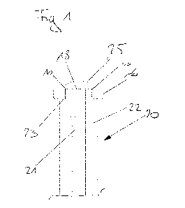
Fig. 1 shows a sectional view of an embodiment of an assembly according to the
invention and manufactured by an embodiment of an inventive method comprising
a
center pin 20 made of a piece 19 of wire or rod having over its length, a core
21 of a first
material which is surrounded by an outer layer 22 of a second material (cf.
Fig. 2 which
shows a sectioned view of such a piece 19 of wire or rod), the second material
being
different from the first material. In this embodiment the middle electrode 6
is welded to
an end of the piece of wire or rod, preferably onto a shoulder cut into the
outer layer 22.
A high energy beam, preferably a laser beam, was directed to the exposed core
21 and
a powder was melted onto the exposed core 21 by the high energy beam such that
in a
contact region 18 of the powder and the exposed core 21 a microstructure
composed of
material of the core 21 and powder was formed after resolidification of the
material of
the core 21 and the powder and the core 21 is covered by resolidified powder
25 at the
one end of the piece 19 of wire or rod. In this embodiment the resolidified
powder 25
covers also the weld seam 10 present between the middle electrode 6 and the
outer
layer 22.
zo Fig. 3a and 3b show an embodiment of a spark plug 1 according to the
invention,
wherein an end of the spark plug 1 facing the combustion chamber, when the
spark
plug 1 is mounted in the internal combustion engine, is shown in more detail.
The spark plug comprises an ignition means 2 executed by a middle electrode 6
and a
ground electrode 7, wherein there is a spark gap 8 between the middle
electrode 6 and
the ground electrode 7. The ground electrode 7 is arranged on the ground
electrode
carrier 9. In this specific embodiment the wall 3, which surrounds the
ignition means 4,
is formed as part of the spark plug body. The spark plug body surrounds the
ground
electrode carrier 9, and the at least one ground electrode 7 is connected to
the ground
electrode carrier 9, e.g. by laser beam welding.
CA 03177639 2022- 11- 2
WO 2021/253061
PCT/AT2020/060248
13
The weld seam 10 is preferably of the kind, that it is part of the chamfer. In
such
embodiments it may therefore be necessary, that the weld seam 10 is deep
enough, so
that the ground electrode carrier 9 is appropriately fixed by the weld seam 10
The manufacturing method can comprise a step, in which a groove for the weld
seam
is manufactured, in a depth, such that at least one part of the weld seam 10
acts as
a connection between the ground electrode carrier 9 and the spark plug body,
even
after the manufacturing of the chamfer 5.
10 The middle electrode 6 is connected to the middle electrode carrier 13 by
laser beam
welding. The middle electrode carrier 13 (comprising or consisting of a metal,
preferably
Nickel) is arranged on an end of a center pin 20 which consists of a piece 19
of wire or
rod having a core 21 and an outer layer 22 such that it contacts the core 21.
Middle
electrode carrier 13 and center pin 20 form an assembly according to the
invention.
The center pin 20 is arranged inside an opening of an isolator 14 which is
made, e. g. of
ceramic.
In order to seal the combustion chamber against the environment, in this
embodiment,
zo the spark plug 1 comprises a sealing area 4, which is designed as chamfer
5. This
chamfer 5 is placed at the wall 3 (which is formed by the spark plug body in
this
embodiment). It should be noted that a center pin 20 according to the
invention can be
used for all types of spark plugs 1, in particular, also for spark plugs 1
which are sealed
against the environment as taught in the art.
The spark plug body (wall 3) further comprises a mounting portion 11, for
mounting the
spark plug 1 in an internal combustion engine and/or in a cylinder head and/or
in a
spark plug sleeve. The mounting portion 11 is provided in this embodiment as
(external)
thread 12.
Fig. lb shows an isometric view of a second embodiment similar to the
embodiment of
Fig. 1a. The only difference is that the weldseam 10 is not present in Fig.
lb.
CA 03177639 2022- 11- 2
WO 2021/253061
PCT/AT2020/060248
14
It can be seen in Fig. lb that the ground electrode 7 is designed as ring
electrode,
wherein the ring electrode surrounds a circularly formed middle electrode 6
and an
annular spark gap 8 is formed between the ground electrode 7 and the middle
electrode
6.
Furthermore, in this embodiment it can be seen, that the chamfer 5 extends to
the
ground electrode carrier 9, with the advantage of an enhanced heat transfer
between
the spark plug body 3 and the spark plug sleeve as well as between the ground
electrode carrier 9 and a spark plug sleeve.
The sealing area 4 in the form of the chamfer 5 is designed with an angle a
with respect
to a perpendicular y of a center axis x of the spark plug 1. This can be seen
in more
detail in Fig. 3b. The chamfer 5 can have an angle a in a wide range, e. g.
between 200
and 45 with respect to the perpendicular y of a center axis x of the spark
plug 1. When
the spark plug 1 is mounted in a spark plug sleeve or directly in a cylinder
head, the
external thread 12 in conjunction with the internal thread of a spark plug
sleeve or the
cylinder head is configured to pre-load the chamfer 5 of the spark plug 1
against a
surface of the spark plug sleeve or the cylinder head, respectively.
zo The spark plug 1 can be substantially symmetric with respect to a
center axis x.
Fig. 3 shows a sectional view of a wire or rod suitable for an assembly
according to the
invention in which it can be seen that the wire or rod is formed as a clad
wire or clad rod
having a core 21 consisting of material (preferably comprising or consisting
of Copper or
a Copper alloy) with a higher thermal conductivity than that of the outer
layer 22. The
core 21 can consist of any material with high thermal conductivity, e. g.
silver or gold.
The outer layer 22 consists of a material (preferably comprising or consisting
of Nickel)
with a higher resistance against hot corrosion than that of the core 21.
Fig. 4a,b show a side view and a sectional view of an assembly according to
the
invention in which a body has been formed on the wire or rod as an
intermediate
product. Such a wire or rod can be obtained in a desired length, e. g. from a
coil 27,
preferably by cutting (cf. Fig. 6a). The first end of the piece of wire or rod
can be treated
CA 03177639 2022- 11- 2
WO 2021/253061
PCT/AT2020/060248
to make it more suitable for the following steps, e. g. by turning, milling,
grinding or
polishing.
It can be provided, that a center pin 20 consisting of a wire or rod can be
manufactured
5 by a drawing process. In this case the core 21 with an exemplary diameter
of e. g. 2 - 3
mm is introduced into the outer layer 22 (e. g. a tube with initial outer
diameter of e. g. 5
mm and an inner diameter of 3,8 mm) in a first step. In a next step said
assembly is
processed by a drawing method, resulting in a wire or rod with a core 21 and
an outer
layer 22 according to the invention. Such drawing processes are well known
from the
10 prior art. The resulting wire or rod can have a diameter of e. g. 3,8
mm, but of course all
diameters are possible to be produced via this drawing technique. In a next
step the
wire or rod can be processed as described above and below.
A powder deposition technique is used for forming the body on one end of the
piece of
15 wire or rod, i. e., the body is manufactured in at least one layer such
that for each layer
an unsolidified powder 26 (cf. Fig. 6b) is deposited on said one end of the
piece of wire
and melted ¨ preferably by a high energy beam (e. g. laser beam 24 ¨ cf. Fig.
6b ¨ or
electron beam) ¨ and resolidifies into a (re-)solidified powder 25 to form the
at least one
layer.
As mentioned, the body serves as an intermediate product for the middle
electrode
carrier 13 and is of a larger dimension with respect to at least one
direction, preferably
with respect to a longitudinal axis of the wire or rod.
In a further manufacturing step (following Fig. Sc) for obtaining the middle
electrode
carrier 13 from the intermediate product material is removed from the body
shown in
this figure to obtain a body with reduced dimensions, preferably with
dimensions
corresponding to the ones of the middle electrode carrier 13 and having the
desired pre-
defined distance d between core 21 of the piece of wire or rod and the
mounting surface
for the middle electrode carrier 13. The desired dimensions are shown in
dashed line in
Fig. 6c
CA 03177639 2022- 11- 2
WO 2021/253061
PCT/AT2020/060248
16
In the embodiment according to Fig. 7 it can be provided, that the wire or rod
is feed to
a manufacturing process, in which at least the outer layer 22 (it can be
provided that
also a small amount of the core diameter is removed, e.g via turning or
milling) is
removed in the area of the one end of the wire or rod, preferably via turning
or milling. In
a next step the layer with a thickness described above is applied to the un-
coated part
of the core 21 in the area of the one end via a powder deposition technique as
described above. After this process - also leading to a shoulder in the area
of the one
end of the wire or rod - a middle electrode can be attached via e. g. a
welding process.
Independent of the embodiment, the beneficial result is to positively
influence the
thermal conductivity due to the fact, that the distance between the middle
electrode
carrier 9 (and therefore to the middle electrode 6) and the core 21 can be
properly
defined.
CA 03177639 2022- 11- 2
WO 2021/253061
PCT/AT2020/060248
17
List of reference signs:
1 spark plug
2 ignition means
3 wall
4 sealing area
5 chamfer
6 middle electrode
7 ground electrode
8 spark gap
9 ground electrode carrier
10 weld seam
11 mounting portion
12 external thread
13 middle electrode carrier
14 isolator
15 powder nozzle
16 anti-rotation lock
17 intendation
18 contact region of the powder and the exposed core
19 piece of wire or rod
20 center pin
21 core
22 outer layer
23 shoulder
24 laser beam
25 (re-)solidified powder
26 (unsolidified) powder
27 coil of wire or rod
28 powder nozzle
CA 03177639 2022- 11- 2
WO 2021/253061
PCT/AT2020/060248
18
d distance
x center axis of spark plug
y perpendicular y of center axis of spark plug
a angle with respect to perpendicular of center axis of spark
plug
CA 03177639 2022- 11- 2