Note: Descriptions are shown in the official language in which they were submitted.
CA 03177842 2022-09-28
WO 2021/229307 PCT/1B2021/020027
MOISTURE DETECTION IN GASES CONVEYING MEDICAL CONDUITS
INCORPORATION BY REFERENCE TO ANY PRIORITY APPLICATIONS
[0001] Any and all applications for which a foreign or domestic
priority claim is
identified in the Application Data Sheet as filed with the present application
are hereby
incorporated by reference under 37 CFR 1.57.
FIELD OF THE DISCLOSURE
[0002] The present disclosure relates to detecting moisture in a
conduit. More
particularly, the present disclosure describes a respiratory or surgical gases
conveying system
which is capable of detecting the presence, amount and/or location of one or
more of
condensation, humidity and/or bodily fluids.
BACKGROUND
[0003] Respiratory assistance apparatuses and surgical insufflators
provide a flow
of gases or a flow of pressurized gases through a conduit system to a patient.
For a range of
applications using these and similar devices, it is beneficial to humidify the
supplied gases.
These applications include where the gases are inspired and/or where the gas
is being supplied
during surgery to a surgery site of a patient. A downside to providing
humidified gases through
a conduit is the potential for condensation to form within the conduit. In
addition to
condensation, other types of moisture may also be introduced into a conduit
from the patient
(for example, in the form of bodily fluids such as saliva, blood, mucus), an
optional heat and
moisture exchanger (HME), an optional nebulizer, and/or the environment (such
as via a room-
entraining ventilator, or through a liquid- or vapor-permeable conduit wall,
for example).
SUMMARY OF THE DISCLOSURE
[0004] Humidified gases can cool as they pass through a conduit system
between
a gases source and the gases delivery destination. This can result in moisture
(or liquid) forming
inside the conduit as the gases cool. Moisture can refer to condensate, water,
or the presence
of any liquid in the conduit The formation of moisture is typically
undesirable in respiratory
assistance apparatuses and surgical insufflators. For example, condensation in
a conduit can
lead to a condition referred to as "rain out." Rain out occurs when moisture
forms and
potentially runs down the walls of the conduit system. The moisture can pool
in a low part of
the conduit system or it can run out of the conduit system into the patient's
respiratory system,
-1-
CA 03177842 2022-09-28
WO 2021/229307 PCT/1B2021/020027
body, back in to the gases source or into a ventilator return or other device
connected to a
conduit of a respiratory assistance apparatus or surgical insufflator. All of
these rain out effects
are undesirable and can cause numerous complications. Similarly, fluids from
other sources
(including the patient, other equipment and/or the environment) may be
undesirable, and/or
should be monitored for other reasons.
[0005] As used herein, the phrase "conduit system" encompasses any
conduits
(also referred to herein as tubes), connectors or patient interfaces that
convey gases between a
gases source and a patient and/or convey expired gases from the patient to
another component
of the respiratory assistance apparatus or surgical insufflator. For example,
as discussed in
further detail below, the conduit system can include one or more of
inspiratory tube(s),
expiratory tube(s), insufflation tube(s), connector(s), Y-piece(s), patient
tube(s), and/or patient
interface(s) (including masks, nasal cannulas, nasal pillows, endotracheal
tubes, tracheostomy
tubes, surgical cannulas, etc.). Further, moisture, condensate, condensation
and liquid are
generally used synonymously in the present disclosure as would be understood
by a person of
skill in the art from the contextual usage of those terms herein.
[0006] Respiratory assistance apparatuses and surgical insufflators
(collectively
referred to herein as gases supply systems) can employ one or more heating
wires within the
conduit system or in the walls of any or all components of the conduit system
to provide a heat
source. The one or more heating wires allow the conduit to control the
temperature and/or
relative humidity of the gases to a desired value or range as the gases pass
through the conduit
system, reducing the potential for condensation. One or more sensor wires can
also be included
within or in the walls of the conduit system as well. The one or more sensor
wires are typically
used to convey temperature measurement information of the humidified gases
flowing through
a conduit and/or patient interface from one or more temperature sensors back
to a controller of
the gases supply system. The gases supply system can use the temperature
measurement
information in a feedback control system to adjust the amount of heat provided
by the one or
more heating wires or other components of the gases supply system.
[0007] Even with heating wires, condensation and rain out can still
occur, and
fluids from other sources may still be introduced. The present disclosure
provides for detecting
moisture. Moisture can be detected by measuring or inferring capacitance,
reactance and/or
impedance or a change in capacitance, reactance and/or impedance of two or
more spaced
-2-
CA 03177842 2022-09-28
WO 2021/229307 PCT/1B2021/020027
electrical conductors within the conduit system or embedded in the conduit
system walls.
These electrical conductors can be, for example, one or more conductive wires,
such as the one
or more heating wires and/or the one or more sensor wires. Alternatively, or
additionally,
dedicated conductors may be provided within, or embedded in, the conduit
system including
the lumen of the conduit. The capacitance can be an intrinsic/parasitic
capacitance. The
measure can use a time response and/or a frequency response of the wire(s).
Moisture can also
be detected by measuring a change in resistance as disclosed herein and/or a
change to a
wireless signal such as an RF signal.
[0008] The present disclosure provides a humidifier system useable in a
gases
supply system, the humidifier system comprising a humidifier; a conduit
comprising a first
electrically conductive element and a second electrically conductive element;
and a controller
configured to monitor a signal using one or more of the first electrically
conductive element
and the second electrically conductive element to determine a value indicative
of moisture in
the conduit based at least in part on the signal. The signal can be indicative
of a capacitance
between the first electrically conductive element and the second electrically
conductive
element. The signal can be indicative of a change in capacitance between the
first electrically
conductive element and the second electrically conductive element. The
controller can
comprise a signal generator. The controller can comprise one or more hardware
and/or
software processors. The first electrically conductive element and the second
electrically
conductive element can be separated by a distance configured to allow for a
capacitive charge
to be sensed between the first electrically conductive element and the second
electrically
conductive element. The humidifier system can also comprise a dielectric
material located
between the first electrically conductive element and the second electrically
conductive
element. The dielectric material can be vapor or liquid permeable. The vapor
permeable
dielectric material can allow evaporation of water to ambient air while
inhibiting passage of
liquid water and breathing gases to ambient air. The controller can be
configured to determine
the value indicative of moisture on a comparison of a measurement of the first
electrically
conductive element and/or the second electrically conductive element. The
value indicative of
moisture can comprise a time constant of a circuit comprising the first
electrically conductive
element or the second electrically conductive element in series with the
reference resistor. The
signal can be indicative of a time constant or a resonant frequency of a
circuit comprising the
-3-
CA 03177842 2022-09-28
WO 2021/229307 PCT/1B2021/020027
first electrically conductive element and/or the second electrically
conductive element. The
signal can be indicative of a change in a time constant or a change in a
resonant frequency of
a circuit comprising the first electrically conductive element and/or the
second electrically
conductive element The value inductive of moisture in the conduit corresponds
to an
inductance of the conduit. The value inductive of moisture in the conduit
corresponds to a
change in inductance of the conduit. The humidifier system can also comprise a
resonant circuit
wherein an inductor is placed in parallel with a capacitor. The resonant
circuit can be
electrically connected in parallel with the first electrically conductive
element, the second
electrically conductive element, or both the first electrically conductive
element and the second
electrically conductive element. The resonant circuit can be tuned to exhibit
resonant behavior
when sufficiently excited by the signal. The resonant circuit can be tuned to
exhibit resonant
behavior when excited by the signal, wherein the signal has been selected to
excite the resonant
circuit. The controller can be configured to apply additional power to the
first electrically
conductive element in conjunction with a normal control power. The humidifier
system can
also comprise an AC power supply. The humidifier system can also comprise a DC
power
supply. The signal can be indicative of a temperature of the first
electrically conductive element
or the second electrically conductive element. The signal can be indicative of
a change in
temperature of the first electrically conductive element or the second
electrically conductive
element. The signal can be indicative of a thermal conductivity of a medium
between the first
electrically conductive element and the second electrically conductive
element, or the signal
can be indicative of a thermal conductivity of a medium proximal to the first
electrically
conductive element or the second electrically conductive element. The signal
can be indicative
of a change in thermal conductivity of a medium between the first electrically
conductive
element and the second electrically conductive element, or the signal can be
indicative of a
change in thermal conductivity of a medium proximal to the first electrically
conductive
element or the second electrically conductive element. A change in temperature
of the first
electrically conductive element or the second electrically conductive element
can be
substantially linear. The signal can be indicative of a temperature difference
between the first
electrically conductive element and the second electrically conductive
element. The second
electrically conductive element can measure the signal. The signal can
correspond to a
resistance of the second electrically conductive element, the resistance of
the second
-4-
CA 03177842 2022-09-28
WO 2021/229307 PCT/1B2021/020027
electrically conductive element varying with the temperature of the second
electrically
conductive element. The first electrically conductive element or the second
electrically
conductive element can further comprise a thermistor. The first electrically
conductive element
or the second electrically conductive element can further comprise a diode.
The diode can be
electrically connected in parallel with the thermistor. The diode can be
electrically connected
in parallel, and positioned substantially adjacent, with the thermistor. The
first electrically
conductive element and the second electrically conductive element can be
adjacent to each
other. The first electrically conductive element and the second electrically
conductive element
can be not adjacent to each other. The first electrically conductive element
and the second
electrically conductive element can be within a bead of the conduit The first
electrically
conductive element can measure the signal. The signal can be indicative of a
resistance of the
first electrically conductive element or the second electrically conductive
element. The signal
can be indicative of a resistance of a medium between the first electrically
conductive element
and the second electrically conductive element. The first electrically
conductive element or the
second electrically conductive element can comprise at least two portions that
are electrically
disconnected from one another. The first electrically conductive element and
the second
electrically conductive element can be electrically insulated from other
electrically conductive
elements for a portion of a length of the first electrically conductive
element and for a portion
of a length of the second electrically conductive element. The at least two
portions can protrude
into a lumen of the conduit. The at least two portions can be flush with an
inner wall of the
conduit. The at least two portions can be arranged within the tube wall and
are pneumatically
coupled with the lumen of the conduit. The at least two portions that can be
electrically
disconnected from one another can be in series with one another. The at least
two portions that
can be electrically disconnected from one another can be in parallel with one
another. The
controller can determine a value indicative of moisture in the conduit based
at least in part on
a magnitude and/or phase of the signal. The humidifier system can also
comprise a signal
generator. The signal can have a frequency between 30 Hz and 300 GHz. The
signal can have
a frequency between 1 MHz and 100 MHz. The signal can have a frequency of
about 10 MHz.
The first electrically conductive element and/or the second electrically
conductive element can
be a quarter of the wavelength of the signal. The wavelength of the signal can
be four times
larger than the length of the first electrically conductive element and/or the
second electrically
-5-
CA 03177842 2022-09-28
WO 2021/229307 PCT/1B2021/020027
conductive element. The signal generator can inject the signal into the first
electrically
conductive element. The first electrically conductive element can be
configured to be a
transmitter. The second electrically conductive element can be configured to
be a receiver to
receive the signal transmitted by the first electrically conductive element.
The magnitude
and/or phase of the signal can be measured by a radio-frequency transducer.
The radio-
frequency transducer can be an AM receiver, RF sampling ADC, or RF rectifier.
The
humidifier system can also comprise a filter to filter the signal. The filter
can comprise a high
pass or bandpass filter. The filter can be configured to filter out the mains
frequency. The filter
can be configured to filter out frequencies between 50 ¨ 60 Hz. The
transmitter can comprise
a loop antenna. The receiver can comprise a loop antenna. The receiver can
comprise a
monopole antenna. The transmitter can comprise a monopole antenna. The first
electrically
conductive element can be electrically coupled to a first switch. The second
electrically
conductive element can be electrically coupled to a second switch. The first
switch can be
configured to electrically disconnect one end of the first electrically
conductive element. The
second switch can be configured to electrically disconnect one end of the
second electrically
conductive element. The first switch and/or the second switch can be located
in any one of the
following: a heater base, a sensor cartridge, the conduit, an external
component, or an
intermediate connector.
[0009] The controller can be configured to output an alarm if the value
indicative
of moisture falls below a first threshold value. The controller can be
configured to output an
alarm if the value indicative of condensation exceeds a second threshold
value. The alarm
indicates an unacceptable level of moisture. The controller can be configured
to automatically
reduce humidification of breathing or insufflation gases in response to the
value indicative of
moisture and/or humidity in the conduit. The reduction of humidity delivered
to the patient can
be achieved by a reduction in heater plate power. The conduit can be a
composite conduit. The
conduit can comprise a vapor and/or liquid permeable bead. The permeable bead
can allow
evaporation of water to ambient air while inhibiting passage of liquid water
and breathing gases
to ambient air. The permeable bead can be one or more of an activated
perfluorinated polymer
material having extreme hydrophilic properties, hydrophilic thermoplastic,
breathable
thermoplastic copolyester, woven treated fabric exhibiting breathable
characteristics, or a
hydrophilic polyester block copolymer. The first conductive element and the
second
-6-
CA 03177842 2022-09-28
WO 2021/229307 PCT/1B2021/020027
electrically conductive element can be spirally wound about at least a length
of the conduit.
The first conductive element and the second electrically conductive element
can be spirally
wound within, through or around the conduit The first conductive element and
the second
electrically conductive element can form part of the conduit walls. The first
electrically
conductive element can be a sensing wire. The first electrically conductive
element can be a
heater wire. The second electrically conductive element can be a sensing wire.
The second
electrically conductive element can be a heater wire.
[0010] The present disclosure provides a method of detecting an
indication of
moisture in a conduit of a gases supply system used to transport respiratory
or surgical gases,
the method comprising determining a presence and/or level of moisture based at
least in part
on property of the conduit. The determination of the presence or level of
moisture can be
inferred from a dielectric property of the conduit The determination of the
property can
comprise applying a signal to a first electrically conductive element in the
conduit.
determination of the property can comprise measuring a capacitance between the
first
electrically conductive element and a second electrically conductive element
The
determination of the property can comprise measuring a capacitance between the
first
electrically conductive element and a second electrically conductive element
based on the
applied signal. The determination of the property comprises measuring an
indication of a time
constant or a resonant frequency of a circuit comprising the first
electrically conductive
element. The determination of the property can comprise processing a value
indicative of an
inductance. The determination of the property can further comprise measuring
an indication of
a resistance of the first electrically conductive element. The determination
of the property can
further comprise measuring an indication of a temperature. The determination
of the property
can further comprise measuring an indication of a thermal conductivity. The
determination of
the property can further comprise measuring a magnitude and/or phase of a
signal. The conduit
can be the conduit of any of conduit implementations disclosed herein. The
method uses the
humidifier system of any humidifier system disclosed herein.
[0011] The present disclosure provides a method of detecting moisture
in a conduit
utilized to transport humidified gases, the method comprising providing two
electrically
conductive elements separated by a dielectric and located within, around or on
the conduit and
-7-
CA 03177842 2022-09-28
WO 2021/229307 PCT/1B2021/020027
measuring a capacitance or change in capacitance to indicate a measure of
moisture or
condensate within the conduit.
[0012] The present disclosure provides a method of detecting moisture
in a conduit
utilized to transport humidified gases, the method comprising providing two
electrically
conductive elements located within, around or on the conduit and measuring a
resistance or a
change in resistance to indicate a measure of moisture or condensate within
the conduit. The
method uses the conduit of any of conduit implementations disclosed herein.
The method uses
the humidifier system of any humidifier system disclosed herein.
[0013] The present disclosure provides a method of detecting moisture
in a conduit
utilized to transport humidified gases, the method comprising providing two
electrically
conductive elements located within, around or on the conduit and measuring a
time constant,
a resonant frequency, a change in a time constant, or a change in a resonant
frequency to
indicate a measure of moisture or condensate within the conduit The method
uses the conduit
of any of conduit implementations disclosed herein. The method uses the
humidifier system of
any humidifier system disclosed herein.
[0014] The present disclosure provides a method of detecting moisture
in a conduit
utilized to transport humidified gases, the method comprising providing two
electrically
conductive elements located within, around or on the conduit and measuring a
resistance or a
change in resistance to indicate a measure of moisture or condensate within
the conduit. The
method uses the conduit of any of conduit implementations disclosed herein.
The method uses
the humidifier system of any humidifier system disclosed herein.
[0015] The present disclosure provides a method of detecting moisture
in a conduit
utilized to transport humidified gases, the method comprising providing two
electrically
conductive elements located within, around or on the conduit and measuring a
temperature or
a change in temperature to indicate a measure of moisture or condensate within
the conduit.
The method uses the conduit of any of conduit implementations disclosed
herein. The method
uses the humidifier system of any humidifier system disclosed herein.
[0016] The present disclosure provides a method of detecting moisture
in a conduit
utilized to transport humidified gases, the method comprising providing two
electrically
conductive elements and located within, around or on the conduit and measuring
a thermal
conductivity or a change in thermal conductivity to indicate a measure of
moisture or
-8-
CA 03177842 2022-09-28
WO 2021/229307 PCT/1B2021/020027
condensate within the conduit. The method uses the conduit of any of conduit
implementations
disclosed herein. The method uses the humidifier system of any humidifier
system disclosed
herein.
[0017] The present disclosure provides a method of detecting moisture
in a conduit
utilized to transport humidified gases, the method comprising providing two
electrically
conductive elements and located within, around or on the conduit and measuring
a magnitude
and/or phase of a signal or a change in a magnitude and/or phase of a signal
to indicate a
measure of moisture or condensate within the conduit. The method uses the
conduit of any of
conduit implementations disclosed herein. The method uses the humidifier
system of any
humidifier system disclosed herein.
[0018] The present disclosure provides external accessories. An example
of an
external accessory is a cartridge for use with a humidifier in a respiratory
or surgical
humidification system. The present disclosure provides a cartridge for use
with a humidifier in
a respiratory or surgical humidification system, the cartridge comprising one
or more sensors
for sensing a property of a gases flow in a removable humidification chamber
of the humidifier;
a first electrical connector configured to make an electrical connection with
a corresponding
electrical connector of the humidifier; a second electrical connector
configured to make an
electrical connection with a corresponding electrical connector of an
inspiratory conduit
removably engageable with the cartridge, wherein the second electrical
connector can
comprise at least a first electrical terminal or pad and a second electrical
terminal or pad
configured to make an electrical coupling with a first electrically conductive
element and a
second electrically conductive element extending along at least a portion of a
length of the
inspiratory conduit; and a controller communicatively coupled with the one or
more sensors
and the first electrically conductive element and the second electrical
connectors. The cartridge
can be removably attachable to the humidifier and the controller can be
configured to, in use,
measure a signal indicative of a capacitance between the first electrically
conductive element
and the second electrically conductive element of the removable inspiratory
conduit.
[0019] The present disclosure provides a cartridge for use with a
humidifier in a
respiratory or surgical humidification system, the cartridge comprising one or
more sensors for
sensing a property of a gases flow in a removable humidification chamber of
the humidifier; a
first electrical connector configured to make an electrical connection with a
corresponding
-9-
CA 03177842 2022-09-28
WO 2021/229307 PCT/1B2021/020027
electrical connector of the humidifier; a second electrical connector
configured to make an
electrical connection with a corresponding electrical connector of an
inspiratory conduit
removably engageable with the cartridge, wherein the second electrical
connector can
comprise at least a first electrical terminal or pad and a second electrical
terminal or pad
configured to make an electrical coupling with a first electrically conductive
element and a
second electrically conductive element extending along at least a portion of a
length of the
inspiratory conduit; and a controller communicatively coupled with the one or
more sensors
and the first electrically conductive element and the second electrical
connectors. The cartridge
can be removably attachable to the humidifier and the controller can be
configured to, in use,
measure a signal indicative of a time constant or a resonant frequency of a
circuit comprising
the first electrically conductive element and the second electrically
conductive element of the
removable inspiratory conduit.
[0020] The present disclosure provides a cartridge for use with a
humidifier in a
respiratory or surgical humidification system, the cartridge comprising one or
more sensors for
sensing a property of a gases flow in a removable humidification chamber of
the humidifier; a
first electrical connector configured to make an electrical connection with a
corresponding
electrical connector of the humidifier; a second electrical connector
configured to make an
electrical connection with a corresponding electrical connector of an
inspiratory conduit
removably engageable with the cartridge, wherein the second electrical
connector can
comprise at least a first electrical terminal or pad and a second electrical
terminal or pad
configured to make an electrical coupling with a first electrically conductive
element and a
second electrically conductive element extending along at least a portion of a
length of the
inspiratory conduit; and a controller communicatively coupled with the one or
more sensors
and the first electrically conductive element and the second electrical
connectors. The cartridge
can be removably attachable to the humidifier and the controller can be
configured to, in use,
measure a signal indicative of a resistance of the first electrically
conductive element or the
second electrically conductive element of the removable inspiratory conduit.
[0021] The present disclosure provides a cartridge for use with a
humidifier in a
respiratory or surgical humidification system, the cartridge comprising one or
more sensors for
sensing a property of a gases flow in a removable humidification chamber of
the humidifier; a
first electrical connector configured to make an electrical connection with a
corresponding
-10-
CA 03177842 2022-09-28
WO 2021/229307 PCT/1B2021/020027
electrical connector of the humidifier; a second electrical connector
configured to make an
electrical connection with a corresponding electrical connector of an
inspiratory conduit
removably engageable with the cartridge, wherein the second electrical
connector can
comprise at least a first electrical terminal or pad and a second electrical
terminal or pad
configured to make an electrical coupling with a first electrically conductive
element and a
second electrically conductive element extending along at least a portion of a
length of the
inspiratory conduit; and a controller communicatively coupled with the one or
more sensors
and the first electrically conductive element and the second electrical
connectors. The cartridge
can be removably attachable to the humidifier and the controller can be
configured to, in use,
measure a signal indicative of a temperature of the first electrically
conductive element or the
second electrically conductive element of the removable inspiratory conduit.
100221 The present disclosure provides a cartridge for use with a
humidifier in a
respiratory or surgical humidification system, the cartridge comprising one or
more sensors for
sensing a property of a gases flow in a removable humidification chamber of
the humidifier; a
first electrical connector configured to make an electrical connection with a
corresponding
electrical connector of the humidifier; a second electrical connector
configured to make an
electrical connection with a corresponding electrical connector of an
inspiratory conduit
removably engageable with the cartridge, wherein the second electrical
connector can
comprise at least a first electrical terminal or pad and a second electrical
terminal or pad
configured to make an electrical coupling with a first electrically conductive
element and a
second electrically conductive element extending along at least a portion of a
length of the
inspiratory conduit; and a controller communicatively coupled with the one or
more sensors
and the first electrically conductive element and the second electrical
connectors. The cartridge
can be removably attachable to the humidifier and the controller can be
configured to, in use,
measure a signal indicative of a thermal conductivity of a medium between the
first electrically
conductive element and the second electrically conductive element of the
removable
inspiratory conduit. The present disclosure provides a cartridge for use with
a humidifier in a
respiratory or surgical humidification system, the cartridge comprising one or
more sensors for
sensing a property of a gases flow in a removable humidification chamber of
the humidifier; a
first electrical connector configured to make an electrical connection with a
corresponding
electrical connector of the humidifier; a second electrical connector
configured to make an
-11-
CA 03177842 2022-09-28
WO 2021/229307 PCT/1B2021/020027
electrical connection with a corresponding electrical connector of an
inspiratory conduit
removably engageable with the cartridge, wherein the second electrical
connector can
comprise at least a first electrical terminal or pad and a second electrical
terminal or pad
configured to make an electrical coupling with a first electrically conductive
element and a
second electrically conductive element extending along at least a portion of a
length of the
inspiratory conduit; and a controller communicatively coupled with the one or
more sensors
and the first electrically conductive element and the second electrical
connectors. The cartridge
can be removably attachable to the humidifier and the controller can be
configured to, in use,
measure magnitude and/or phase of a signal or a change in a magnitude and/or
phase of a signal
between the first electrically conductive element and the second electrically
conductive
element of the removable inspiratory conduit.
100231 The present disclosure provides a humidifier useable in a gases
supply
system, the humidifier comprising a humidification chamber configured to
humidify a gases
supply; an inspiratory conduit connector configured to connection with an
inspiratory conduit
including a first electrically conductive element and a second electrically
conductive element;
a controller configured to monitor a signal using one or more of the first
electrically conductive
element and the second electrically conductive element to determine a value
indicative of
moisture in the conduit based at least in part on the signal. The controller
can be further
configured to monitor the signal. The signal can be indicative of a
capacitance between the
first electrically conductive element and the second electrically conductive
element. The signal
can be indicative of a change in capacitance between the first electrically
conductive element
and the second electrically conductive element. The signal can be indicative
of a time constant
or a resonant frequency of the first electrically conductive element or the
second electrically
conductive element. The signal can be indicative of a temperature of the first
electrically
conductive element or the second electrically conductive element. The signal
can be indicative
of a change in temperature of the first electrically conductive element or the
second electrically
conductive element. The signal can be indicative of a thermal conductivity of
a medium
between the first electrically conductive element or the second electrically
conductive element,
or the signal or the signal is indicative of a thermal conductivity of a
medium proximal to the
first electrically conductive element or the second electrically conductive
element. The signal
can be indicative of a change in thermal conductivity of a medium between the
first electrically
-12-
CA 03177842 2022-09-28
WO 2021/229307 PCT/1B2021/020027
conductive element or the second electrically conductive element, or the
signal or the signal is
indicative of a change in thermal conductivity of a medium proximal to the
first electrically
conductive element or the second electrically conductive element. The signal
can be indicative
of a temperature difference between the first electrically conductive element
and the second
electrically conductive element. The value indicative of moisture can be a
magnitude and/or
phase of a signal or a change in a magnitude and/or phase of a signal. The
controller can
comprise a signal generator. The controller can comprise one or more hardware
and/or
software processors. The humidifier can further comprise the conduit of any of
conduit
implementations disclosed herein.
100241 The present disclosure provides a conduit used with a
respiratory or surgical
gases supply system, the conduit comprising a first electrically conductive
element; a second
electrically conductive element spaced apart from the first electrically
conductive element at a
distance configured to allow a capacitive effect to exist between the first
electrically conductive
element and the second electrically conductive element such that the
capacitive effect changes
in the presence of moisture; and a material separating the first conductive
element from the
second electrically conductive element. At least one of the electrically
conductive elements
can be one or more of a heater wire or sensor wire. The conduit can further
comprise a
controller configured to determine a presence and/or indication of moisture
within the conduit
by determining a capacitance or change in capacitance between the first
electrically conductive
element and the second electrically conductive element. The controller can be
one or more
microprocessors. The controller can use the first electrically conductive
element and second
electrically conductive element to determine the presence or the indication of
moisture within
the conduit by measuring a capacitive reactance and/or inductance existing
between the first
electrically conductive element and the second electrically conductive element
The first
electrically conductive element and second electrically conductive element can
be placed close
enough to allow for a measurable capacitance, but far enough apart to allow
for a measurable
change in capacitance due to a presence of moisture.
[0025] The present disclosure provides a conduit used with a
respiratory or surgical
gases supply system, the conduit comprising a first electrically conductive
element; a second
electrically conductive element, wherein one or more of the first electrically
conductive
element and the second electrically conductive element are configured to
provide a
-13-
CA 03177842 2022-09-28
WO 2021/229307 PCT/1B2021/020027
measurement of a time constant or a resonant frequency indicative of a
presence or amount of
moisture in a conduit. The conduit can further comprise a resonant circuit
wherein an inductive
element is electrically connected in parallel with a capacitive element One or
more of the first
electrically conductive element and the second electrically conductive element
can be
configured to be electrically connected in parallel with a resonant circuit
wherein an inductive
element is electrically connected in parallel with a capacitive element. The
resonant circuit can
be external to the conduit. The resonant circuit can be tuned to exhibit
resonant behavior when
excited by a signal. One or more of the first electrically conductive element
and the second
electrically conductive element can be configured to be electrically connected
in parallel with
a signal generator. The conduit can comprise a controller configured to
determine a presence
and/or indication of moisture within the conduit by determining a time
constant, a resonant
frequency, a change in time constant, or a change in resonant frequency. One
or more of the
first electrically conductive element and the second electrically conductive
element can be
configured to be electrically connected in parallel with the controller. The
controller can
comprise a signal generator. The controller can be one or more
microprocessors.
[00261 The present disclosure provides a conduit used with a
respiratory or surgical
gases supply system, the conduit comprising a first electrically conductive
element; a second
electrically conductive element, wherein one or more of the first electrically
conductive
element and the second electrically conductive element are configured to
provide a
measurement of a resistive property indicative of a presence or amount of
moisture in a conduit.
The first electrically conductive element or the second electrically
conductive element can
comprise at least two portions that are electrically disconnected from one
another. The at least
two portions can protrude into a lumen of the conduit The at least two
portions can be flush
with an inner wall of the conduit. The at least two portions can be arranged
within the tube
wall and can be pneumatically coupled with the lumen of the conduit. The at
least two portions
that can be electrically disconnected from one another can be in series with
one another. The
at least two portions that can be electrically disconnected from one another
can be in parallel
with one another. The conduit can further comprise a controller configured to
determine a
presence and/or indication of moisture within the conduit by determining a
resistance or change
in resistance. The controller can be one or more microprocessors.
-14-
CA 03177842 2022-09-28
WO 2021/229307 PCT/1B2021/020027
[0027] The present disclosure provides a conduit used with a
respiratory or surgical
gases supply system, the conduit comprising a first electrically conductive
element; a second
electrically conductive element, wherein one or more of the first electrically
conductive
element and the second electrically conductive element are configured to
provide a
measurement of a temperature or thermal conductivity property indicative of a
presence or
amount of moisture in a conduit. The first electrically conductive element or
the second
electrically conductive element can further comprise a thermistor. The first
electrically
conductive element or the second electrically conductive element can further
comprise a diode.
The diode can be electrically connected in parallel with the thermistor. The
diode can be
electrically connected in parallel, and positioned substantially adjacent,
with the thermistor.
The first electrically conductive element and the second electrically
conductive element can
be adjacent to each other. The first electrically conductive element and the
second electrically
conductive element can be not adjacent to each other. The first electrically
conductive element
and the second electrically conductive element can be within a bead of the
conduit. The conduit
can further comprise a controller configured to determine a presence and/or
indication of
moisture within the conduit by determining a temperature, a thermal
conductivity, a change in
temperature, or a change in thermal conductivity of the first electrically
conductive element or
the second electrically conductive element. The controller can be configured
to apply
additional power to the first electrically conductive element in conjunction
with a normal
control power. The controller can be one or more microprocessors.
[0028] The present disclosure provides a conduit used with a
respiratory or surgical
gases supply system, the conduit comprising a first electrically conductive
element; a second
electrically conductive element, wherein one or more of the first electrically
conductive
element and the second electrically conductive element are configured to
measure a magnitude
and/or phase of a signal or a change in a magnitude and/or phase of a signal
indicative of a
presence or amount of moisture in a conduit. The first electrically conductive
element can be
configured to be a transmitter. The second electrically conductive element can
be configured
to be a receiver to receive a signal transmitted by the first electrically
conductive element. The
transmitter can comprise a loop antenna. The receiver can comprise a loop
antenna. The
transmitter can comprise a monopole antenna. The receiver can comprise a
monopole antenna.
The first electrically conductive element can be electrically coupled to a
first switch. The
-15-
CA 03177842 2022-09-28
WO 2021/229307 PCT/1B2021/020027
second electrically conductive element can be electrically coupled to a second
switch. The first
switch can be configured to electrically disconnect one end of the first
electrically conductive
element and the second switch can be configured to electrically disconnect one
end of the
second electrically conductive element. The conduit can further comprise a
controller
configured to determine a presence and/or indication of moisture within the
conduit by
determining a magnitude and/or phase of a signal or a change in a magnitude
and/or phase of
a signal in the first electrically conductive element or the second
electrically conductive
element. The controller can be one or more microprocessors.
[0029] The material can be a fluid permeable material. The first
electrically
conductive element and second electrically conductive element can be elongate
filaments. The
elongate filament can be surrounded by an electrically insulating jacket. The
first electrically
conductive element and second electrically conductive element can be spirally
wound about at
least a portion of a length of the conduit The first electrically conductive
element and second
electrically conductive element extend from one end of the conduit to the
other end of the
conduit The first electrically conductive element and second electrically
conductive element
extend only a portion of a length from one end of the conduit to the other end
of the conduit.
The conduit can include and/or communicate with a controller configured to
determine a
presence and/or indication of moisture within the conduit by determining a
capacitance or
change in capacitance between the first electrically conductive element and
the second
electrically conductive element. The conduit can be a composite conduit The
first electrically
conductive element and second electrically conductive element form part of a
wall of the
conduit. The first electrically conductive element and second electrically
conductive element
can form part of a bead disposed in a composite conduit. Alternatively, the
first conductive
element and second electrically conductive element can be disposed in the
conduit such that
the first conductive element and second electrically conductive element can
freely move within
the conduit. The material can be a vapor and/or liquid permeable material. The
material can
allow evaporation of water to ambient air while inhibiting passage of liquid
water and
breathing gases to ambient air. The material can be a one or more of an
activated peifluorinated
polymer material having extreme hydrophilic properties, hydrophilic
thermoplastic, breathable
thermoplastic copolyester, woven treated fabric exhibiting breathable
characteristics, or a
hydrophilic polyester block copolymer. The conduit can further comprise
microstructures
-16-
CA 03177842 2022-09-28
WO 2021/229307 PCT/1B2021/020027
configured to use capillary action to move moisture. The vapor and/or liquid
permeable
material can be a dielectric material. The conduit further can comprise
microstructures
configured to wick moisture across a portion of the first electrically
conductive element and/or
the second electrically conductive element The conduit further can comprise
openings
configured to convey moisture by capillary action between the first
electrically conductive
element and the second electrically conductive element The conduit further can
comprise a
wicking material configured to convey moisture between the first electrically
conductive
element and the second electrically conductive element. The first electrically
conductive
element and the second electrically conductive element can be ribbon wires.
The first
electrically conductive element and the second electrically conductive element
can be
comprised within a permeable, non-permeable or partially permeable and non-
permeable bead.
The first electrically conductive element and the second electrically
conductive element and
bead can be coextruded. The conduit can further comprise an electrically
conductive mesh. A
spacing between the first electrically conductive element and the second
electrically
conductive element can be variable depending a presence and/or amount of
moisture present
within the conduit. The material can cause the first electrically conductive
element and the
second electrically conductive element to touch or separate based on a
presence of moisture.
The material can comprise an opening, keyhole, dip, channel and/or void
configured to allow
moisture between the first electrically conductive element and the second
electrically
conductive element and affect a capacitive effect between the first
electrically conductive
element and the second electrically conductive element. The first electrically
conductive
element and the second electrically conductive element can be sensitive to
touching of the
conduit. The material can comprise an accordion shape that expands or
contracts in the
presence of moisture, thereby moving the first electrically conductive element
and the second
electrically conductive element further apart or closer together. The material
can cause the first
electrically conductive element and the second electrically conductive element
to touch or
separate based on a presence of moisture.
[0030] The present disclosure provides a humidifier system useable in a
gases
supply system, the humidifier system comprising: a humidifier; a conduit
comprising a
conductive element; and a controller configured to monitor a signal using the
electrically
conductive element to determine a value indicative of moisture in the conduit
based at least in
-17-
CA 03177842 2022-09-28
WO 2021/229307 PCT/1B2021/020027
part on the signal. The signal can be indicative of a time constant or a
resonant frequency of
the electrically conductive element. The signal can be indicative of a change
in a time constant
or a change in a resonant frequency of the electrically conductive element.
The value can be
indicative of moisture in the conduit corresponds to an inductance of the
conduit. The value
indicative of moisture in the conduit can correspond to a change in inductance
of the conduit.
The humidifier system can further comprise a resonant circuit wherein an
inductive element is
electrically connected in parallel with a capacitive element. The resonant
circuit can be
electrically connected in parallel with the electrically conductive element.
The humidifier
system can further comprise a signal generator. The controller can comprise a
signal generator.
The controller can comprise one or more hardware and/or software processors.
The resonant
circuit can be tuned to exhibit resonant behavior when sufficiently excited by
the signal. The
resonant circuit can be tuned to exhibit resonant behavior when excited by the
signal, wherein
the signal has been selected to excite the resonant circuit. The controller
can be configured to
apply additional power to the electrically conductive element in conjunction
with a normal
control power. The humidifier system can further comprise an AC power supply.
The
humidifier system can further comprise a DC power supply. The signal can be
indicative of a
temperature of the electrically conductive element. The signal can be
indicative of a change
temperature of the electrically conductive element. The signal can be
indicative of a thermal
conductivity of a medium proximal to the electrically conductive element The
signal can be
indicative of a change in thermal conductivity of a medium proximal to the
electrically
conductive element. A change in temperature of the electrically conductive
element can be
substantially linear. The electrically conductive element can further comprise
a thermistor. The
electrically conductive element can further comprise a diode. The diode can be
electrically
connected in parallel with the thermistor. The diode can be electrically
connected in parallel,
and positioned substantially adjacent, with the thermistor. The electrically
conductive element
can be within a bead of the conduit. The electrically conductive element can
measure the signal.
The controller can be configured to output an alarm if the value indicative of
moisture falls
below a first threshold value. The controller can be configured to output an
alarm if the value
indicative of moisture exceeds a second threshold value. The alarm indicates
an unacceptable
level of moisture. The alarm indicates an unacceptable level of moisture. The
controller can be
configured to automatically reduce humidification of breathing or insufflation
gases in
-18-
CA 03177842 2022-09-28
WO 2021/229307 PCT/1B2021/020027
response to the value indicative of moisture and/or humidity in the conduit.
The reduction of
humidity delivered to the conduit can be achieved by a reduction in heater
plate power. The
conduit can be a composite conduit. The conduit can comprise a vapor and/or
liquid permeable
bead. The permeable bead can allow evaporation of water to ambient air while
inhibiting
passage of liquid water and breathing gases to ambient air. The permeable bead
can be one or
more of an activated perfluorinated polymer material having extreme
hydrophilic properties,
hydrophilic thermoplastic, breathable thermoplastic copolyester, woven treated
fabric
exhibiting breathable characteristics, or a hydrophilic polyester block
copolymer. The
electrically conductive element can be spirally wound about at least a length
of the conduit.
The electrically conductive element can be spirally wound within, through or
around the
conduit. The electrically conductive element can form part of the conduit
walls. The
electrically conductive element can be a sensing wire. The electrically
conductive element can
be a heater wire.
[00311 The present disclosure provides a method of detecting moisture
in a conduit
utilized to transport humidified gases, the method comprising providing an
electrically
conductive elements located within, around or on the conduit and measuring a
time constant,
a resonant frequency, a change in a time constant, or a change in a resonant
frequency to
indicate a measure of moisture or condensate within the conduit. The method
uses the conduit
of any of conduit implementations disclosed herein. The method uses the
humidifier system of
any humidifier system disclosed herein.
[0032] The present disclosure provides a method of detecting moisture
in a conduit
utilized to transport humidified gases, the method comprising providing an
electrically
conductive elements located within, around or on the conduit and measuring a
temperature or
a change in temperature to indicate a measure of moisture or condensate within
the conduit.
The method uses the conduit of any of conduit implementations disclosed
herein. The method
uses the humidifier system of any humidifier system disclosed herein.
[00331 The present disclosure provides a method of detecting moisture
in a conduit
utilized to transport humidified gases, the method comprising providing an
electrically
conductive elements and located within, around or on the conduit and measuring
a thermal
conductivity or a change in thermal conductivity to indicate a measure of
moisture or
condensate within the conduit. The method uses the conduit of any of conduit
implementations
-19-
CA 03177842 2022-09-28
WO 2021/229307 PCT/1B2021/020027
disclosed herein. The method uses the humidifier system of any humidifier
system disclosed
herein.
100341 The present disclosure provides a cartridge for use with a
humidifier in a
respiratory or surgical humidification system, the cartridge comprising one or
more sensors for
sensing a property of a gases flow in a removable humidification chamber of
the humidifier; a
first electrical connector configured to make an electrical connection with a
corresponding
electrical connector of the humidifier; a second electrical connector
configured to make an
electrical connection with a corresponding electrical connector of an
inspiratory conduit
removably engageable with the cartridge, wherein the second electrical
connector can
comprise at least one electrical terminal or pad configured to make an
electrical coupling with
an electrically conductive element extending along at least a portion of a
length of the
inspiratory conduit; and a controller communicatively coupled with the one or
more sensors
and the first and the second electrical connectors. The cartridge can be
removably attachable
to the humidifier, and the controller can be configured to, in use, measure a
signal indicative
of a time constant or a resonant frequency of a circuit comprising the
electrically conductive
element of the removable inspiratory conduit.
[0035] The present disclosure provides a cartridge for use with a
humidifier in a
respiratory or surgical humidification system, the cartridge comprising one or
more sensors for
sensing a property of a gases flow in a removable humidification chamber of
the humidifier; a
first electrical connector configured to make an electrical connection with a
corresponding
electrical connector of the humidifier; a second electrical connector
configured to make an
electrical connection with a corresponding electrical connector of an
inspiratory conduit
removably engageable with the cartridge, wherein the second electrical
connector can
comprise at least one electrical terminal or pad configured to make an
electrical coupling with
an electrically conductive element extending along at least a portion of a
length of the
inspiratory conduit; and a controller communicatively coupled with the one or
more sensors
and the first and the second electrical connectors. The cartridge can be
removably attachable
to the humidifier, and the controller can be configured to, in use, measure a
signal indicative
of a temperature of the electrically conductive element of the removable
inspiratory conduit.
[0036] The present disclosure provides a cartridge for use with a
humidifier in a
respiratory or surgical humidification system, the cartridge comprising one or
more sensors for
-20-
CA 03177842 2022-09-28
WO 2021/229307 PCT/1B2021/020027
sensing a property of a gases flow in a removable humidification chamber of
the humidifier; a
first electrical connector configured to make an electrical connection with a
corresponding
electrical connector of the humidifier; a second electrical connector
configured to make an
electrical connection with a corresponding electrical connector of an
inspiratory conduit
removably engageable with the cartridge, wherein the second electrical
connector can
comprise at least one electrical terminal or pad configured to make an
electrical coupling with
an electrically conductive element extending along at least a portion of a
length of the
inspiratory conduit; and a controller communicatively coupled with the one or
more sensors
and the first and the second electrical connectors. The cartridge can be
removably attachable
to the humidifier, and the controller can be configured to, in use, measure a
signal indicative
of a thermal conductivity of a medium proximal to the electrically conductive
element of the
removable inspiratory conduit.
[0037] The present disclosure provides a humidifier useable in a gases
supply
system, the humidifier comprising a humidification chamber configured to
humidify a gases
supply; an inspiratory conduit connector configured to connection with an
inspiratory conduit
including an electrically conductive element; a controller configured to
monitor a signal using
the electrically conductive element to determine a value indicative of
moisture in the conduit
based at least in part on the signal. The signal can be indicative of a time
constant or a resonant
frequency of the electrically conductive element. The signal can be indicative
of a temperature
of the electrically conductive element. The signal can be indicative thermal
conductivity of a
medium proximal to the electrically conductive element The controller can
comprise a signal
generator. The controller can comprise one or more hardware and/or software
processors. The
humidifier can further comprise the conduit of any of conduit implementations
disclosed
herein.
[0038] The present disclosure provides a conduit used with a
respiratory or surgical
gases supply system, the conduit comprising an electrically conductive
element, wherein the
electrically conductive element is configured to provide a measurement of a
time constant or
a resonant frequency indicative of a presence or amount of moisture in a
conduit. The conduit
can further comprise a resonant circuit wherein an inductive element is
electrically connected
in parallel with a capacitive element The resonant circuit can be external to
the conduit. The
resonant circuit can be tuned to exhibit resonant behavior when sufficiently
excited by the
-21-
CA 03177842 2022-09-28
WO 2021/229307 PCT/1B2021/020027
signal. The resonant circuit can be tuned to exhibit resonant behavior when
excited by the
signal, wherein the signal has been selected to excite the resonant circuit.
The electrically
conductive element can be configured to be electrically connected in parallel
with a signal
generator. The conduit can further comprise a controller configured to
determine a presence
and/or indication of moisture within the conduit by determining a time
constant, a resonant
frequency, a change in time constant, or a change in resonant frequency. The
electrically
conductive can be configured to be electrically connected in parallel with the
controller. The
controller can comprise a signal generator. The controller can comprise one or
more
microprocessors.
100391 The present disclosure provides a conduit used with a
respiratory or surgical
gases supply system, the conduit comprising an electrically conductive
element, wherein the
electrically conductive element is configured to provide a measurement of an
temperature or
thermal conductivity property indicative of a presence or amount of moisture
in a conduit The
electrically conductive element can further comprise a thermistor. The
electrically conductive
element can further comprise a diode. The diode can be electrically connected
in parallel with
the thermistor. The diode can be electrically connected in parallel, and
positioned substantially
adjacent, with the thermistor. The electrically conductive element can be
within a bead of the
conduit. The conduit can further comprise a controller configured to determine
a presence
and/or indication of moisture within the conduit by determining a temperature
and/or a change
in temperature of the electrically conductive element, and/or by determining a
thermal
conductivity of a medium proximal to the electrically conductive element
and/or a change in
thermal conductivity of a medium proximal to the electrically conductive
element. The
controller can be configured to apply additional power to the electrically
conductive element
in conjunction with a normal control power. The controller can be one or more
microprocessors
[0040] The present disclosure can be applied to any known conduit with
two
electrically conductive elements. The material can be a fluid permeable
material. The
electrically conductive element can be elongate filaments. The elongate
filament can be
surrounded by an electrically insulating jacket. The electrically conductive
element can be
spirally wound about at least a portion of a length of the conduit. The
electrically conductive
element extend from one end of the conduit to the other end of the conduit.
The electrically
conductive element extend only a portion of a length from one end of the
conduit to the other
-22-
CA 03177842 2022-09-28
WO 2021/229307 PCT/1B2021/020027
end of the conduit The conduit can be a composite conduit. The electrically
conductive
element can form part of a wall of the conduit. The electrically conductive
element can form
part of a bead disposed in a composite conduit. Alternatively, the first
conductive element and
second electrically conductive element can be disposed in the conduit such
that the first
conductive element and second electrically conductive element can freely move
within the
conduit The material can be a vapor and/or liquid permeable material. The
material can allow
evaporation of water to ambient air while inhibiting passage of liquid water
and breathing gases
to ambient air. The material can be a one or more of an activated
perfluorinated polymer
material having extreme hydrophilic properties, hydrophilic thermoplastic,
breathable
thermoplastic copolyester, woven treated fabric exhibiting breathable
characteristics, or a
hydrophilic polyester block copolymer. The conduit can further comprise
microstructures
configured to use capillary action to move moisture. The vapor and/or liquid
permeable
material can be a dielectric material. The conduit further can comprise
microstructures
configured to wick moisture across a portion of the electrically conductive
element. The
conduit further can comprise openings configured to convey moisture by
capillary action. The
conduit further can comprise a wicking material configured to convey moisture.
The
electrically conductive element can be ribbon wires. The electrically
conductive element can
be comprised within a permeable, non-permeable or partially permeable and non-
permeable
bead. The electrically conductive element and bead can be coextruded. The
conduit can further
comprise an electrically conductive mesh. The electrically conductive element
can be sensitive
to touching of the conduit.
[0041] Although discussed mainly with respect to respiratory assistance
apparatuses and surgical insufflators, it is to be understood that the
moisture detection
disclosure provided by the present application can also apply to other medical
or non-medical
uses of a conduit or humidified gases transport system where it is desirable
to detect a presence
or extent of moisture.
BRIEF DESCRIPTION OF THE DRAWINGS
[0042] These and other features, aspects, and advantages of the present
disclosure
are described with reference to the drawings of certain implementations, which
are intended to
schematically illustrate certain implementations and not to limit the
disclosure.
-23-
CA 03177842 2022-09-28
WO 2021/229307 PCT/1B2021/020027
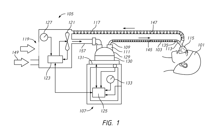
[0043] Fig. 1A illustrates schematically an example respiratory
humidifier system.
[0044] Fig. 1B illustrates an example humidifier.
[0045] Fig. 1C illustrates an example heater base and cartridge.
[0046] Fig. 1D illustrates an example humidifier with the
electropneumatic
connector disconnected from the humidifier of FIG. 1B.
[0047] Fig, lE illustrates an example heater base and humidification
chamber.
[0048] Fig. 1F illustrates an example cartridge.
[0049] Fig. 1G illustrates the electropneumatic connector of the
humidifier of Fig.
1B
100501 Fig. 2 illustrates schematically an example surgical humidifier
system.
100511 Fig. 3A shows a side-plan view of a section of an example
composite
conduit.
[0052] Fig. 3B shows a longitudinal cross-section of a top portion a
tube similar to
the example composite conduit of Fig. 3A.
[0053] Fig. 3C shows another longitudinal cross-section illustrating a
first elongate
member in the composite conduit.
[0054] Fig. 4A illustrates condensation interaction with a non-
permeable bead of a
composite conduit.
[0055] Fig. 4B illustrates condensation interaction with a permeable
bead of a
composite conduit.
[0056] Fig. 5 illustrates an example modeled circuit system of a
condensation
detection system using capacitance to detect condensation.
[0057] Fig. 6 illustrates an example modeled circuit system of a
condensation
detection system using a time constant or resonance frequency derived from
inductance to
detect condensation.
[0058] Fig. 7 illustrates an example modeled circuit system of a
condensation
detection system using resistance to detect condensation.
[0059] Fig. 8 illustrates an example modeled circuit system of a
condensation
detection system using resistance and short-circuiting to detect condensation.
[0060] Fig. 9A illustrates schematically an example condensation
detection system
using signal attenuation to detect condensation.
-24-
CA 03177842 2022-09-28
WO 2021/229307 PCT/1B2021/020027
[0061.] Fig. 9B illustrates a conduit wall structures configured to
detect moisture
using signal attenuation.
[0062] Fig. 10A illustrates an example modeled circuit system of a
condensation
detection system using signal attenuation to detect condensation.
[0063] Fig. 10B illustrates an example modeled circuit system of a
condensation
detection system using signal attenuation to detect condensation with
monopoles.
[0064] Fig. 11A illustrates heat radiating from wires in a bead.
[0065] Fig. 11B illustrates an example modeled circuit system of a
condensation
detection system using temperature or thermal conductivity to detect
condensation.
[0066] Fig. 12 illustrates a table of resistor voltage vs. time
constant in a
condensation detection system.
[0067] Fig. 13A illustrates a flow chart of a condensation detection
mode.
[0068] Fig. 13B illustrates a flow chart of a condensation measurement
mode.
[0069] Fig. 13C illustrates a flow chart of a condensation measurement
mode using
resonant frequency.
[00701 Fig. 13D illustrates a flow chart of a condensation measurement
mode using
signal attenuation.
[0071] Fig. 13E illustrates a flow chart of a condensation measurement
mode using
thermal conductivity.
[0072] Fig. 14 illustrates an example bead. various conduit wall
structures
configured to detect moisture.
[0073] Fig. 15 illustrates an example configuration of a bead with an
opening.
[0074] Fig. 16 illustrates a second example configuration of a bead
with an
opening.
[0075] Fig. 17A illustrates an example configuration cross section of a
part of the
tube wall.
[0076] Fig. 17B illustrates a second example configuration cross
section of a part
of the tube wall.
[0077) Fig. 18 illustrates a portion of the tube wall with parallel
elements.
[0078] Fig. 19 illustrates a portion of the tube wall where the
elements can pivot.
[0079] Fig. 20 illustrates an example of a permeable wall portion of a
conduit wall.
-25-
CA 03177842 2022-09-28
WO 2021/229307 PCT/1B2021/020027
[0080] Fig. 21 illustrates a second example of a permeable wall portion
of a conduit
wall.
[0081] Fig. 22 illustrates an example conduit configuration where
elements are in
the same plane, parallel to the surface of the exterior conduit wall.
[0082] Fig. 23 illustrates a cross section of an example conduit
wherein the
elements are provided longitudinally, parallel to the lumen, and equidistantly
spaced about the
circumference of the tube
[0083] Fig. 24 illustrates a cross section of an example conduit
wherein an
additional conductive element wound about the outside of the conduit wall.
[0084] Fig. 25 illustrates a cross section of an example conduit
wherein individual
strands of two meshes can be insulated and multiplexed.
DETAILED DESCRIPTION OF THE DISCLOSURE
[0085] Although certain implementations and examples are described
below, those
of skill in the art will appreciate that the disclosure extends beyond the
specifically disclosed
implementations and/or uses and obvious modifications and equivalents thereof.
Thus, it is
intended that the scope of the disclosure herein disclosed should not be
limited by any
particular implementations described below. For example, the dimensions
provided in the
present disclosure are examples and not being limiting. Similarly, although
described mainly
with respect to respiratory or surgical humidification systems, the present
disclosure is
applicable to any tubing arrangement where it is desirable to measure
moisture. The following
examples describe detection of a presence and, optionally, volume and/or
location of
condensation in particular (for example, condensed water or other humidifying
liquids), but
the disclosed methods and apparatuses may alternatively or additionally be
applied to detect
humidity of the gases and/or the presence of other moisture or fluids within
the conduit system.
Example Gases Supply Systems
[0086] Fig, 1 schematically illustrates an example respiratory
assistance apparatus
including a conduit system comprising one or more conduits 103, 117, a patient
interface 115
and a Y-piece 135. The respiratory assistance apparatus may be a ventilator, a
continuous,
variable, or bi-level positive airway pressure (PAP) system or other form of
respiratory
therapy, such as, for example, high flow therapy.
-26-
CA 03177842 2022-09-28
WO 2021/229307 PCT/1B2021/020027
[0087] Gases may be transported in the breathing circuit of Fig, 1 as
follows. Dry
or relatively dry gases pass from a gases source 105 through a dry line tube
157 to a humidifier
107, which humidifies the dry gases. The gases source 105 may be, for example,
a ventilator
or a blower. The humidifier 107 connects to an end 109 of a conduit, such as
inspiratory tube
103, via a port 111. The inspiratory tube 103 is connected to a patient 101
through a patient
interface 115, optionally using a Y-piece 113. An optional expiratory conduit,
such as
expiratory tube 117, also connects to the patient interface 115 through the Y-
piece 113. The
expiratory tube may be configured to move exhaled gases away from the patient
101. As
illustrated in Fig. 1, expiratory tube 117 returns exhaled gases from the
patient 101 to the gases
source 105. Alternatively, the inspiratory tube 103 connects directly to the
patient interface
115 without a Y-piece 113. In such an implementation, expired gases are
allowed to flow
directly to the ambient environment.
[0088] Inspiratory tube 103 can include electrically conductive
elements such as
heater, sensor and/or moisture detection elements 145. Similarly, expiratory
tube 117 can
include heater, sensor and/or moisture detection elements 147. Further, the Y-
piece 113 and
patient interface 115 can also include heater, sensor and/or moisture
detection elements. As
will be explained in further detail below, the heater, sensor and/or moisture
detection elements
145, 147 can be wires or filaments.
[0089] As shown in the example respiratory assistance apparatus of Fig,
1, dry or
relatively dry gases enter the gases source 105 through a vent 119. A fan 121
may improve gas
flow into the gases source 105 by drawing air or other gases through the vent
119. The fan 121
may be, for instance, a variable speed fan, where an electronic controller 123
controls the fan
speed. The electronic controller 123 may also be controlled by a second
electronic controller
125, or vice versa, in some implementations.
[0090] The humidifier 107 can include a humidification chamber 129
containing a
volume of water 130 or other suitable humidifying liquid. The humidification
chamber 129
can be removable from the humidifier 107. The humidification chamber 129 may
include a
highly heat-conductive base (for example, an aluminum base) contacting or
associated with a
heater plate 131 on the humidifier 107.
[0091] The humidifier 107 may also include electronic controls. In Fig.
1, for
example, the humidifier 107 includes an electronic, analog, or digital
controller 125. The
-27-
CA 03177842 2022-09-28
WO 2021/229307 PCT/1B2021/020027
controller 125 may be a microprocessor-based controller executing computer
software
commands stored in associated memory. in response to humidity, temperature or
other
feedback values provided via a user interface 133 and/or integrated sensors,
the controller 125
determines heat, flow, pressure and/or other variables used to provide
humidified gases to a
patient (also referred to herein as a user). User interface 133 can be one or
more hardware
buttons and/or a display or touch screen display. The display can provide
audio and/or visual
feedback to the user. When condensation is detected, any number of alarms,
alerts, feedback,
guidance or instructions can be provided to the user to indicate the presence,
extent or remedies
for a condensation condition. For example, the user interface can provide an
alarm when
condensation is detected. The user interface can provide a visual indication
of condensation.
The user interface can also provide an animation to instruct a user how to
properly drain
condensation.
[0092] Any suitable patient interface may be used. Patient interface is
a broad term
and is to be given its ordinary and customary meaning to a person of ordinary
skill in the art
(that is, it is not to be limited to a special or customized meaning) and
includes, without
limitation, masks (such as tracheal mask, face masks, and nasal masks),
endotracheal tubes,
tracheostomy tubes, cannulas, and nasal pillows. A temperature probe 135 may
be incorporated
in or connected to inspiratory tube 103 near the Y-piece 113, or directly to
the Y-piece 113 or
the patient interface 115. The temperature probe 135 monitors the temperature
of the flow of
gases near or at the patient interface 115. A heating wire (such as element
145) may be used to
adjust the temperature of the patient interface 115, the Y-piece 113, and/or
the inspiratory tube
103 to maintain the temperature of the flow of gases above the saturation
temperature, thereby
reducing the opportunity for unwanted condensation, and/or to deliver the
gases at optimal
temperature for patient therapy (for example, 40 C at the patient end of the
inspiratory tube
and/or 37 C at the patient for non-invasive therapy). As shown in Fig. 1,
exhaled gases are
optionally returned from the patient interface 115 to the gases source 105 via
the expiratory
tube 117.
[0093] The system of Fig. 1 may be readily adapted for other
applications involving
the supply of a heated and/or humidified gas flow to a user or patient,
including but not limited
to laparoscopy, and the like. Such applications may use alternative gases,
operating parameters
(e.g., flow, pressure, temperature, or humidity) and patient interfaces.
Further, although shown
-28-
CA 03177842 2022-09-28
WO 2021/229307 PCT/1B2021/020027
with respect to a separate ventilator and humidifier system, it is to be
understood that the
present disclosure can also be used with an integrated ventilator/blower and
humidifier system.
[0094] The system of Fig. 1 can also provide oxygen (GO or an 02
fraction to the
user through port 149. The system of Fig. 1 can receive 02 from a remote
source and/or by
blending atmospheric air with incoming 0/ from the remote source. The blending
of
atmospheric air and incoming 02 can occur via a Venturi or a similar inlet
located in gases
source 105 or humidifier 107.
[0095] Fig, 1B illustrates in more detail an example respiratory
humidifier. Aside
from the differences described below, the humidifier is otherwise similar to
the humidifier 107
of the system illustrated in Fig. 1A.
[0096] The illustrated humidifier comprises a heater base 151 with a
heater plate,
a user interface and a controller; a removable and replaceable humidification
chamber 153;
and a removable and replaceable cartridge 155. The humidification chamber 153
is received
by the heater base 151, in thermal contact with the heater plate 152.
[0097] The cartridge 155 houses electronics and one or more sensors
which sense
one or more properties of gases flowing through the humidification chamber in
use. The
sensors may be provided on probes protruding from the cartridge and through an
aperture in
the inlet or outlet of the humidification chamber, in use. The cartridge also
comprises an
electrical connector which makes an electrical connection with the heater base
for
communication (for example, serial communication) with the controller. The
cartridge may
further house, in part or in whole, electronics configured to determine or
infer a capacitance or
change in capacitance of the inspiratory tube, as described in further detail
below, and
communicate this to the controller via the electrical connector. The cartridge
therefore
preferably comprises a microcontroller communicatively coupled with the
sensor(s) and the
controller. Alternatively, or additionally, the controller provided within the
heater base, in part
or in whole, may be configured to determine or infer the capacitance from data
received from
the sensor(s) via the electrical connection.
[0098] In use, the outlet of a dry line tube 157 receiving a flow of
gases from a
gases source is pneumatically coupled with the inlet of the humidification
chamber 153, and
an inspiratory tube 159 comprising an electropneumatic connector 161 is
electrically coupled
with the cartridge and pneumatically coupled with the outlet of the
humidification chamber
-29-
CA 03177842 2022-09-28
WO 2021/229307 PCT/1B2021/020027
153 to transport the humidified flow of gases towards the patient. The
electropneumatic
connector makes a releasable and lockable connection with the humidification
chamber and/or
cartridge, and comprises release buttons 163.
100991 The electropneumatic connector 161, shown in further detail in
Fig. 1C,
comprises electrical terminals or pads 171 respectively coupled with a pair of
sensor wires 173
and a pair of heater wires 175 embedded within the inspiratory tube, forming
respective sensing
and heating loops. It also comprises electrical terminals or pads 171
electrically coupled with
an identification resistor or other identification element embedded within the
electropneumatic
connector 161, which may be used by the humidifier to identify the type of
inspiratory tube
coupled with the cartridge. As described in further detail, moisture within
the inspiratory
conduit may be detected from a measure of capacitance between the electrically-
isolated
heating and sensing loops. The connector may further comprise additional wires
or conductors
configured to detect moisture within the inspiratory tube, alone or in
combination with one or
more of the sensor or heater wires. Corresponding moisture detection terminals
or pads 171
can also be included. Alternatively, the additional wires or conductors may be
electrically
coupled with the 'identification' terminals or pads in place of the
identification resistor or other
identification element, and may optionally have a predetermined resistance (or
a resistance
within a predetermined range), capacitance, or resonant frequency unique to
each tube model.
This arrangement provides the dual functionality of identification and
moisture detection. For
example, a moisture-detection wire having a particular resistance may be used
by the
humidifier to identify the tube as being configured for capacitive moisture
detection, and/or
enable calibration of the cartridge and/or heater base for moisture detection
with that particular
tube model.
[0100] The aforementioned electrical terminals or pads 171 of the
electropneumatic connector 161 are configured to make an electrical connection
with
corresponding pads or terminals on the cartridge (155 of Fig, 1 B). Thus,
existing humidifier
bases may be retrofitted with a replacement cartridge comprising any
additional electronics
and/or electrical pads or terminals required to detect moisture in the
inspiratory tube. Similarly,
the disclosed humidifier may be retrofitted with a replacement cartridge for
compatibility with
alternative inspiratory conduits, if necessary. Alternatively, the electrical
terminals or pads of
the electropneumatic connector and cartridges may be arranged so that selected
"core"
-30-
CA 03177842 2022-09-28
WO 2021/229307 PCT/1B2021/020027
terminals or pads make electrical connections with corresponding terminals or
pads of two or
more different cartridges, while "optional" terminals or pads make electrical
connections only
with specific terminals or pads of selected cartridges configured to make use
of those
connections.
[0101] At a
distal (patient) end of the inspiratory conduit, there is provided a
temperature sensor electrically coupled to the pair of embedded sensing wires,
forming the
sensing loop, and the heating wires are also electrically coupled with each
other, forming the
heating loop. The additional wire(s) or conductor(s) may similarly be
electrically coupled at
the distal end of the tube, although this may not be required in at least some
implementations.
[0102] The
cartridge may further comprise a connector and/or cable configured for
connection to a corresponding connector of the expiratory conduit (147 of Fig.
1A) to supply
power to expiratory heating wire(s). In some implementations, the cartridge
and expiratory
conduit may alternatively or additionally be configured to detect moisture in
the expiratory
tube, with the connector and/or cable providing the required electrical
connections.
[0103] Fig,
2 illustrates an example surgical insufflation device that can be used,
for example, in a laparoscopy procedure. The laparoscopic cannula 207 can be
connected to a
gases delivery conduit 206, for example, via a Luer lock connector 4. The
cannula 207 can be
used to deliver gases into a surgical site, such as within the cavity of the
patient 2. The cannula
207 can include one or more passages to introduce gases and/or one or more
surgical
instruments into the surgical cavity. The surgical instrument can be a scope,
electrocautery
tool, or any other instrument The surgical instrument can be coupled to an
imaging device,
which can have a screen. The imaging device can be part of a surgical stack,
which can include
a plurality of surgical tools and/or apparatuses.
[0104] The
humidifier chamber 205 can optionally or preferably be in serial
connection to a gases supply 9 via a further conduit 204. The gases supply 9
can provide one
or more insufflation gases, such as carbon dioxide, to the humidifier chamber
205. The gases
supply can provide a continuous gases flow or an intermittent gases flow. The
gases can be
humidified as they are passed through the humidifier chamber 205, which can
contain a volume
of water 220.
[0105] A
humidifier that incorporates the humidifier chamber 205 can be any type
of humidifier. The humidifier chamber 205 can include a plastic formed chamber
having a
-31-
CA 03177842 2022-09-28
WO 2021/229307 PCT/1B2021/020027
metal or otherwise conductive base sealed thereto. The base can be in contact
with the heater
plate 212 during use. The volume of water 220 contained in the chamber 205 can
be heated by
a heater plate 212, which can be under the control of a controller or control
means 208 of the
humidifier. The volume of water 220 within the chamber 205 can be heated such
that it
evaporates, mixing water vapor with the gases flowing through the chamber 205
to heat and
humidify the gases.
[0106] The controller or control means 208 can be housed in a
humidifier base unit
221, which can also house the heater plate 212. The heater plate 212 can have
an electric
heating element therein or in thermal contact therewith. The humidifier base
unit 221 and/or
the heater plate 212 can be removably engageable with the humidifier chamber
205. The
humidifier chamber 205 can also alternatively or additionally include an
integral heater.
[0107] A temperature sensor can also be located at or near the outlet
209 to monitor
a temperature of the humidified gases leaving the humidifier chamber 205 from
the outlet 209.
Additional sensors can also optionally be incorporated, for example, for
sensing characteristics
of the gases (such as temperature, humidity, flow, or others) at a patient end
or anywhere along
the gases delivery conduit 206. The temperature sensor can be connected to the
controller 208
through a sensor wire within, throughout, or around gases delivery conduit 206
[0108] The gases can exit out through the humidifier's outlet 209 and
into the gases
delivery conduit 206. The gases can move through the gases delivery conduit
206 into the
surgical cavity of the patient 2 via the cannula 207, thereby inflating and
maintaining the
pressure within the cavity. Preferably, the gases leaving the outlet 209 of
the humidifier
chamber 205 can have a relative humidity of around 100%. The gases travel
along the gases
delivery conduit 206. As with all of the various example humidifier systems
discussed above,
"rain out" can occur such that water vapor can condense on a wall of the gases
delivery conduit
206. Condensate can have undesirable effects, such as detrimentally reducing
the water content
of the gases delivered to the patient. In order to reduce and/or minimize the
occurrence of
condensation within the gases delivery conduit 206, a heater wire 210 can be
provided within,
throughout, or around the gases delivery conduit 206. The heater wire 210 can
be electronically
connected to the humidifier base unit 221, for example by an electrical
pneumatic connector
of gases delivery conduit 206.
-32-
CA 03177842 2022-09-28
WO 2021/229307 PCT/1B2021/020027
Composite Tubes
[0109] Fig. 3A shows a side-plan view of a section of an example
composite
conduit or tube 301. In general, the composite tube 301 comprises a first
elongate member 303
and a second elongate member 305. Member is a broad term and is to be given
its ordinary and
customary meaning to a person of ordinary skill in the art, is not to be
limited to a special or
customized meaning, and includes, without limitation, integral portions,
integral components,
and distinct components. Thus, although Fig. 3A illustrates an implementation
made of two
distinct components, it will be appreciated that in other implementations, the
first elongate
member 303 and second elongate member 305 can also represent regions in a tube
formed
from a single material. Thus, the first elongate member 303 can represent a
hollow portion of
a tube, while the second elongate member 305 can represent a structural
supporting or
reinforcement portion of the tube which adds structural support to the hollow
portion. The
hollow portion and the structural supporting portion can have a spiral
configuration, as
described herein. The composite tube 301 may be used to form the inspiratory
tube and/or the
expiratory tube of any type of system as described above, a coaxial tube as
described below,
or any other tubes as described elsewhere in this disclosure.
[0110] In this example, the first elongate member 303 comprises a
hollow body
spirally wound to form, at least in part, an elongate tube having a
longitudinal axis LA¨LA
and a lumen 307 extending along the longitudinal axis LA¨LA. In at least one
implementation, the first elongate member 303 is helical tubular member.
Preferably, the first
elongate member 303 is flexible. Furthermore, the first elongate member 303 is
preferably
transparent or, at least, semi-transparent or semi-opaque. A degree of optical
transparency
allows a caregiver or user to inspect the lumen 307 for blockage or
contaminants or to confirm
the presence of condensate. A variety of plastics, including medical grade
plastics, are suitable
for the body of the first elongate member 303. Examples of suitable materials
include
Polyolefin elastomers, Polyether block amides, Thermoplastic co-polyester
elastomers,
EPDM-Polypropylene mixtures, and Thermoplastic polyurethanes.
[0111] The hollow body structure of the first elongate member 303
contributes to
the insulating properties to the composite tube 301. An insulating tube 301 is
desirable because,
as explained above, it prevents heat loss. This can allow the tube 301 to
deliver gas from a
-33-
CA 03177842 2022-09-28
WO 2021/229307 PCT/1B2021/020027
heater-humidifier to a patient while ameliorating heat loss and condensation
with minimal
energy consumption.
[0112] The hollow portion of the first elongate member 303 can
optionally be filled
with a gas. The gas can be air, which is desirable because of its low thermal
conductivity
(2.62x10⁻² W/inK at 300K) and very low cost. A gas that is more viscous than
air may also
advantageously be used, as higher viscosity reduces convective heat transfer.
Thus, gases such
as argon (17.72x10 -3 W/mK at 300K), krypton (9.43x10' W/mK at 300K), and
xenon
(5.65x10' W/ mK at 300K) can increase insulating performance. Each of these
gases is non-
toxic, chemically inert, fire-inhibiting, and commercially available. The
hollow portion of the
first elongated member 303 can be sealed at both ends of the tube, causing the
gas within to be
substantially stagnant. Alternatively, the hollow portion can be a secondary
pneumatic
connection, such as a pressure sample line for conveying pressure feedback
from the patient-
end of the tube to a controller. The first elongate member 303 can be
optionally perforated. For
instance, the surface of the first elongate member 303 can be perforated on an
outward-facing
surface, opposite the lumen 307. The hollow portion of the first elongate
member 303 can also
optionally be filled with a liquid. Examples of liquids can include water or
other biocompatible
liquids with a high thermal capacity. For instance, nanofluids can be used. An
example
nanofluid with suitable thermal capacity comprises water and nanoparticles of
substances such
as aluminum.
[0113] The second elongate member 305 is also spirally wound and joined
to the
first elongate member 303 between adjacent turns of the first elongate member
303. The second
elongate member 305 forms at least a portion of the lumen 307 of the elongate
tube. The second
elongate member 305 acts as structural support for the first elongate member
303.
[0114] The second elongate member 305 can optionally be wider at the
base
(proximal the lumen 307) and narrower at the top. For example, the second
elongate member
can be generally triangular in shape, generally T-shaped, or generally Y-
shaped. However, any
shape that meets the contours of the corresponding first elongate member 303
is suitable.
[0115] The second elongate member 305 can be flexible, to facilitate
bending of
the tube. The second elongate member 305 can be less flexible than the first
elongate member
303. This improves the ability of the second elongate member 305 to
structurally support the
first elongate member 303. For example, the modulus of the second elongate
member 305 is
-34-
CA 03177842 2022-09-28
WO 2021/229307 PCT/1B2021/020027
preferably 30 ¨ 50 MPa (or about 30 ¨ 50 MPa). The modulus of the first
elongate member
303 is less than the modulus of the second elongate member 305. The second
elongate member
305 can be solid or mostly solid. hi addition, the second elongate member 305
can encapsulate
or house conductive material, such as heating elements, sensing wires or an
antenna. In some
embodiments, the second elongate member 305 can be extruded. Heating elements
(also
referred to herein as heating wires, heating filaments or filaments) can
minimize the cold
surfaces onto which condensate from moisture-laden air can form. Heating
elements can also
be used to alter the temperature profile of gases in the lumen 307 of
composite tube 301.
Sensing wires may be coupled with a sensor, such as a temperature sensor,
integrated within
or otherwise provided at a distal end of the tube, in use providing
measurements which may be
used by the gases supply system, such as humidifier 107, in a feedback control
system to adjust
the amount of heat provided by the one or more heating wires or other
components of the gases
supply system. A variety of polymers and plastics, including medical grade
plastics, are
suitable for the body of the second elongate member 305. Examples of suitable
materials
include Polyolefin elastomers, Polyether block amides, Thermoplastic co-
polyester
elastomers, EPDM-Polypropylene mixtures, Thermoplastic polyurethanes,
Thermoset and
Thermochromic materials. In some configurations, the first elongate member 303
and the
second elongate member 305 can be made from the same material. The second
elongate
member 305 can also be made of a different color material from the first
elongate member 303,
and can be transparent, translucent or opaque. For example, the first elongate
member 303 can
be made from a clear plastic, and the second elongate member 305 may be made
from an
opaque blue (or other color) plastic.
[0116] This spirally-wound structure comprising a flexible, hollow body
and an
integral support can provide crush resistance, while leaving the conduit wall
flexible enough
to permit short-radius bends without kinking, occluding or collapsing.
Preferably, the tube can
be bent around a 25 mm diameter metal cylinder without kinking, occluding, or
collapsing, as
defined in the test for increase in flow resistance with bending according to
ISO 5367:2014(E),
for example. This structure also can provide a substantially smooth lumen 307
surface (tube
bore), which helps keep the tube free from deposits and improves gas flow. The
hollow body
has been found to improve the insulating properties of a tube, while allowing
the tube to remain
-35-
CA 03177842 2022-09-28
WO 2021/229307 PCT/1B2021/020027
light weight. In other implementations, however, a non-smooth lumen surface or
tube bore
may be preferred, as described below.
[0117] As explained above, the composite tube 301 can be used as an
expiratory
tube and/or an inspiratory tube in a conduit system, or a portion of a conduit
system.
[0118] The first elongate members 303 and second elongate member 305
(with
encapsulated heating elements and sensing wires) may each be extruded adjacent
to each other
onto a rotating mandrel in a double-helix arrangement to form a continuous
length of tubing.
The continuous length of tubing may be cut to any desired lengths appropriate
for use in a
conduit system (severing the heating elements and sensing wires in the
process) and terminated
with appropriate connectors at each end. For example, an inspiratory conduit
may be
terminated with a chamber end connector at one end, for pneumatic coupling
with a
humidification chamber 129 and electrical coupling with a humidifier 107, and
a patient end
connector at the other end for pneumatic coupling with a Y-piece 135 or
patient interface 115.
The patient end connector may comprise an integrated temperature sensor which
is electrically
coupled with the severed sensing wires to form a sensing circuit. At, or near,
the patient end
connector, the severed heating elements may also be electrically coupled with
each other to
form a heating circuit. Alternatively, the heating elements and/or sensing
wires may be
terminated by respective heating and/or sensing terminals in the patient end
connector, for
electrical coupling with another component of the conduit system. At the
chamber end
connector, the severed heating elements and sensing wires may be electrically
coupled with
respective heating and sensing terminals integrated within the chamber end
connector. The
chamber end connector may be configured for simultaneous pneumatic coupling
with the outlet
of the humidification chamber 129 and electrical coupling with the humidifier
107.
Alternatively, the chamber end connector may comprise an electrical socket,
for example, for
independent pneumatic and electrical coupling with the humidification chamber
129 and
humidifier 107, respectively.
[0119] In some implementations, the tube may be further provided with
one or
more intermediate connectors, such as a midpoint connector comprising a diode
enabling either
a first half or an entire length of the tube to be selectively heated by
supplying power to the
heater wires in a first or second polarity. The midpoint connector may
additionally or
alternatively comprise a further sensor, such as a temperature sensor.
Alternatively, two or
-36-
CA 03177842 2022-09-28
WO 2021/229307 PCT/1B2021/020027
more zones of the tube may be configured to be controlled fully independently
of each other,
so that any one or more of the zones may be selectively heated and/or sensed.
[0120] Fig. 3B shows a longitudinal cross-section of a top portion of
the example
composite tube 301 of Fig. 3A. Fig. 3B has the same orientation as Fig. 3A.
This example
further illustrates the hollow-body shape of the first elongate member 303. As
seen in this
example, the first elongate member 303 forms a longitudinal cross-section of
enclosed portions
309. Portions 309 of the first elongate member 303 overlap adjacent wraps of
the second
elongate member 305. A portion 311 of the first elongate member 303 forms the
wall of the
lumen (tube bore).
10121] A gap 313 between adjacent turns of the first elongate member
303 can
improve the overall insulating properties of the composite tube 301.
Furthermore, the gap 313
between adjacent bubbles can increase the heat transfer resistivity (the R
value) and,
accordingly, decreases the heat transfer conductivity of the composite tube
301. This gap
configuration also improves the flexibility of the composite tube 301 by
permitting shorter-
radius bends. A T-shaped second elongate member 305, as shown in Fig. 3B, can
help maintain
a gap 313 between adjacent bubbles. Nevertheless, adjacent portions of first
elongate member
303 can be configured to touch. For example, adjacent portions can be bonded
together. In
such a bonded configuration, an elongate member, such as T-shaped second
elongate member
305 or other shaped member, can be included which is water permeable or made
of wicking
materials in order to improve capacitive measurements in the presence of
condensate as
described further below.
[0122] One or more conductive materials (referred to herein as
"elements,"
"conductive elements" or "filaments") can be disposed in the second elongate
member 305 for
heating and/or sensing the gases flow. In this example, two elements 315 are
encapsulated in
the second elongate member 305, one on either side of the vertical portion of
the "T." The
elements 315 comprise conductive material, such as alloys of Aluminum (Al)
and/or Copper
(Cu), or conductive polymer. Preferably, the material forming the second
elongate member
305 is selected to be non-reactive with the metal in the elements 315 when the
elements 315
reach their operating temperature. The elements 315 may be spaced away from
lumen 307 so
that the elements are not exposed to the lumen 307. At one end of the
composite tube, pairs of
elements can be formed into a connecting loop.
-37-
CA 03177842 2022-09-28
WO 2021/229307 PCT/1B2021/020027
[0123] A plurality of elements can be disposed in the second elongate
member 305.
The elements can be electrically connected together to share a common rail.
For example, a
first element, such as a heating element, can be disposed on a first side of
the second elongate
member 305. A second element, such as a sensing element or wire, can be
disposed on a second
side of the second elongate member 305. An optional third element, such as a
ground element,
can be disposed between the first and second elements. The first, second,
and/or third elements
can be connected together at one end of the second elongate member 305. The
third element
may also be configured to dissipate power to heat the tube and/or gases, and
the humidifier
may comprise a bias generator circuit configured to enable a sensor coupled
with the second
elongate member 305 to be read regardless of whether or not the heater wire is
powered. There
can also be four wires (two heating and two sensing) with respective ends of
each pair being
electrically connected (or continuous) at a distal end of the tube so that the
heating and sensing
circuits are independent from each other. Arrangements can include one, two,
three, four or
more wires. These elements can be connected to the gases supply system using
an electrical
connector that is either separate from or integrated with a pneumatic
connector of the
composite tube. A pitch of the helically wound conduit can be varied in order
to enhance a
capacitive measurement in some areas of the conduit, as described in further
detail below.
[0124] In other implementations, the tube may be provided with one or
more
additional wires or conductive elements, referred to generally as capacitive
wires, provided
specifically for the purpose of providing a capacitive coupling with another
wire or circuit. The
capacitive wire(s) need not necessarily form a closed loop or circuit like the
heating and
sensing wires generally will. The capacitive wire(s) also need not necessarily
extend the full
length of the tube. In some implementations, there may be a plurality of
capacitive wire(s) of
varying length, which may allow a general location of any moisture within the
tube to be
detected.
[0125] In some implementations, the composite tube 301 may comprise
respective
pairs of first and second elongate members 303, 305, wound in a quadruple-
helix arrangement.
In particular, sensing wires may be provided in one of the second elongate
members 305, with
heating wires and at least one capacitive wire provided in the other second
elongate member
305, each separated by the pair of first elongate members 303. Such an
arrangement may be
preferred to provide a moisture-dependent capacitive coupling between the
heating and
-38-
CA 03177842 2022-09-28
WO 2021/229307 PCT/1B2021/020027
capacitive wires, while minimizing any capacitive coupling with the sensing
wires which may
affect sensor readings.
[0126] The above description of a composite tube is not meant to be
limiting, but
is provided as an example only. It is to be understood that any other type of
conduit can be
used with the condensation detection of the present disclosure. This includes
any sized, shaped
or constructed tube that incorporates heating, sensor and/or condensate
detection elements in
the walls of the tube and/or the tube lumen, such as elements which float or
dangle freely
within the tube, as shown in Fig. 3C, or are attached to one or more locations
within the tube.
As showing in Fig. 3C, tube 391 includes walls 393 and floating or dangling
elements 395. As
described in further detail below, moisture may be detected from variations in
the capacitance
between adjacent elements. Different conduit structures have different
properties which may
be exploited to enhance this detection. For example, a helically-wound
elements, such as the
heating element and sensing wires described above with respect to Figs. 3A-3B,
can have
capacitive properties that are relatively high due to the length of the
elements and may detect
condensate anywhere on the conduit wall. On the other hand, a floating element
within the tube
has the advantage that it will tend to settle at the bottom of the conduit
where condensation
may also accumulate, which may be preferable in some arrangements. A floating
element also
need not be extruded with the tube, permitting greater flexibility in the
design of the floating
element (for example, materials, manufacturing methods, and/or variations in
dimensions
along the length of the floating element). As would be understood by a person
of skill in the
art, there are many different types of tubes in use and known within the art,
any one of which
can be used with the present disclosure.
Condensation Detection
Capacitance and Inductance Based Condensation Detection
[0127] When two or more elements are located within a conduit, a
parasitic
capacitance (reactance and/or inductance) may exist between them. Although
this parasitic
capacitance can negatively affect sensor measurements and therefore efforts
have been
employed to mitigate parasitic capacitance effects (for example, as discussed
in
W02018116187A1, incorporated herein in its entirety by reference), it has been
discovered
-39-
CA 03177842 2022-09-28
WO 2021/229307 PCT/1B2021/020027
that the parasitic capacitance can be dependent on moisture within the
conduit, and it can
therefore be used as an indication and/or measure of humidity, moisture, fluid
and/or
condensation (collectively referred to herein as "condensation" for purposes
of brevity). In
some implementations, the measurement of the capacitance does not require any
sensor(s) to
be exposed to the flow path of the gases in the conduit while in other
implementations any
known sensor can be used to measure capacitance. By utilizing existing
conductive elements
within a conduit (for example, existing heating or sensor elements), this
discovery provides an
inexpensive and accurate solution to detect the presence and/or quantity of
condensation within
a conduit without substantial change to the conduit or gases supply system.
Alternatively,
additional conductors specifically for this purpose may be included in a tube.
This may allow
the tube to be designed to minimize parasitic capacitance with the sensing
wires, and/or
otherwise enhance the sensitivity to condensate without compromising
performance of the
heating and/or sensing wires. For example, heating and moisture detection
elements may be
provided in close proximity to each other, with sensing wires spaced apart
and/or embedded in
a non-permeable material. In another arrangement a tube may comprise sensing
wires
embedded in the conduit wall, and heating elements and a dedicated condensate
detection wire
floating freely within the lumen, as shown in Fig. 3C. In another arrangement,
as disclosed
above, sensing wires may be provided in a separate second elongate member 305
to the heating
and moisture detection wires in a quadruple helix tube.
[01281 The dielectric constant between two electrically isolated
conductive
elements, and hence the capacitance, will differ depending on the distance
between the
elements as well as the existence or amount of condensate on the inner wall
surface of the
conduit (or, in the case of a vapor permeable wall, the amount of individual
water molecules
that move into the wall). In other words, the inherent capacitance of the
conduit can change in
accordance to the amount and proximity of condensation present in the tube if
the elements are
at a fixed distance. The distance that the elements are separated requires
design considerations
in order to properly balance element usage. For example, the elements should
be close enough
to create a detectable capacitance, yet spaced enough so that there is
sufficient moisture change
to create the detectable change in capacitance.
[0129] Although the conductive elements (referred to herein as
"elements" for
brevity) are described mainly with respect to wires or filaments, such as
heater wires or sensor
-40-
CA 03177842 2022-09-28
WO 2021/229307 PCT/1B2021/020027
wires, it is to be understood that the elements can be something other than
physical wires. For
example, the elements can be conductive plates, polymers, tapes or ribbons,
conductive ink,
conductive thread or any other conductive materials.
[0130] Fig. 4A schematically illustrates a conduit wall 401, this time
comprising
respective pairs of conductive heating and sensing elements 415, and how
condensate 407
which is present on the inner wall of the tube will effect the dielectric
between any two wires
which are electrically isolated. In some implementations, the elongate member
305 in Figs.
3A-3B is a bead 405. For example in Fig. 4A, bead 405 is not permeable to
fluid. Condensate
407 in this arrangement is therefore adjacent to, rather than directly
between, the heating and
sensing elements 415, but has been found to result in a measurable change in
the parasitic
capacitance between the conductive elements. Alternatively, or additionally,
as described in
further detail below, the profile of the bead 405 may be modified to enhance
sensitivity to
condensate by, for example, providing a channel between adjacent conductive
elements which
is open to the lumen to receive the condensate 407 between two of the elements
415.
[0131] To increase the capacitance between the elements 415, the wires
may be
provided side-by-side in an alternating or interleaved arrangement, that is in
the order heating-
sensing-heating-sensing. Other arrangements, such as heating-sensing-sensing-
heating or
heating-heating-sensing-sensing, may alternatively be used.
[0132] Fig. 4B schematically illustrates a second example where the
bead 405 is
either vapor permeable and/or fluid permeable. It has been found that the
vapor permeable
material enhances the effect of condensation upon the parasitic capacitive
coupling between
the wires, so that it can be detected with greater precision. in one example,
the material can be
vapor permeable such that the material allows evaporation of water to ambient
air while
effectively blocking passage of liquid water and breathing gases to ambient
air. Although using
a vapor or fluid permeable material in an inspiratory tube is generally
undesirable as it will
reduce the humidity of gases delivered to the patient, if it is only used in
the bead 405, this
drying of the gases will be minimized. Further, this material can be covered
on the outside by
another material that is not vapor or fluid permeable material to allow
penetration of vapor or
fluid for measurement purposes without allowing the vapor or fluid to leak to
ambient. For
example, in Fig. 3B, if the proximate portions of elongate members 303 are
joined together, a
vapor or liquid permeable elongate member 305 would not leak to ambient
-41-
CA 03177842 2022-09-28
WO 2021/229307 PCT/1B2021/020027
[0133] A bead 405 can be made from, for example, one or more of an
activated
peifluorinated polymer material having extreme hydrophilic properties (such as
NAFION
branded products), hydrophilic thermoplastic, woven treated fabric exhibiting
breathable
characteristics, a hydrophilic polyester block copolymer (such as SYMPA'TEX
branded
products), a breathable thermoplastic copolyester (TPC) such as ARN1TEL6 VT
3108, or any
other materials which allows evaporation of water vapor to ambient air while
inhibiting or
blocking passage of liquid water and breathing gases to ambient. Using such
materials,
individual molecules 409 can pass through the bead by diffusion, directly
affecting the
dielectric constant between any two electrically isolated wires or elements.
The dielectric
constant will also be affected due to the presence of condensate on the inner
wall of the tube.
It should be noted that the wires can be insulated by a sheath to prevent
short-circuiting and/or
corrosion.
[01341 Hereinafter and throughout the description, a material that
allows the
passage of water molecules through a monolithic wall of the material via the
solution-diffusion
mechanism, without allowing the bulk passage of liquid water or bulk flow of
respiratory gases
all the way through the wall is described as a "breathable" material. It
should be appreciated
by one of skill in the art that the water molecules in the wall are
molecularly dispersed in the
media, and are therefore without a state (solid, liquid, or gas), although
they are sometimes
referred to in the art as vapor (e.g. the rate of transfer is often referred
to as a water vapor
transmission rate or the like). It should further be appreciated that a
monolithic wall does not
contain open channels or through holes from one major surface to another, such
that viruses
could be carried through such channels or holes alongside air or liquid water
drops via the pore
flow mechanism. It should yet further be appreciated that, like all polymers,
some small
molecule transport of respiratory gases (such as oxygen, carbon dioxide or
nitrogen) may occur
in trace or de minimis amounts (i.e. not "bulk" flow), which, for a breathable
material as
defined herein, would typically be at a rate at least an order of magnitude
lower than that for
water molecules. Furthermore, of particular relevance for breathing gases
being delivered to
or from a patient, such small molecule transport of respiratory gases would be
of an amount
less than that allowed for compliance with the relevant standards, for
example, in the leakage
test of ISO 2367:2014 at Section 5.4 tested via the method set out in Annex E,
which is hereby
incorporated by reference in its entirety.
-42-
CA 03177842 2022-09-28
WO 2021/229307 PCT/1B2021/020027
[0135] Other element structures within a conduit can also be used. For
example,
the elements do not need to be comprised within the wall of the conduit, but
could be allowed
to float within the conduit. In such a configuration, the elements are likely
to rest in condensate
at the lowest part of the tube which can allow for improved condensate
detection. Further, a
vapor and/or liquid permeable material could be used to surround and join the
elements in
order to improve condensate measurements. Alternatively, as shown in Fig. 3C,
a liquid water
absorptive, wicking, and/or hydrophilic material 397 such as cotton or an open-
cell foam
material could be used to surround and join the elements 399 in order to
improve condensate
measurements. Such a material also provides the advantage of inhibiting
mobility of the
condensate towards sensors, the patient or the ventilator where condensate is
most undesirable.
Additionally, or alternatively, the conduit can include microstructures, such
as channels, to
transport liquid condensate towards and/or along an appropriate measurement
element by
capillary action. Further examples of these structures are described below
with respect to Figs.
8-18.
[0136] The inner wall of the tube may also have openings (including,
for example,
dips, corrugations, valleys, square channels, and/or undulations of varying
sizes and shapes)
to encourage condensate to accumulate in the openings. For example, this can
include parallel
or helical corrugations or longitudinal channels with valleys adjacent the
relevant elements so
that condensate accumulates where it will influence capacitance between the
elements. This
may provide safety for the patient by reducing the likelihood of condensation
flowing into the
patient interface, and may also provide a specific measurement site.
[0137] In some implementations, a capacitance measurement can be
performed by
generating a signal which passes through the tube along one or more elements.
This is used to
detect and measure, by a detector 507, a time constant dependent on the
inherent capacitance
"C" between that element and one or more adjacent elements. This process is
schematically
represented in Fig. 5. A supplied power step change or pulse, or a series of
pulses, can be used
as the generated signal to measure the change in capacitance. These
measurements can either
coincide or be interleaved with either or both of temperature sensing
measurements or heating
wire usage. Capacitance can also be measured by any known method of measuring
or
determining capacitance.
-43-
CA 03177842 2022-09-28
WO 2021/229307 PCT/1B2021/020027
[0138] Fig. 5A schematically illustrates a signal generator 501, a
conduit system
503, a resistor R 505 and a detector 507. The signal generator 501, resistor
505 and detector
507 would generally be integrated within a humidifier in electrical
communication with the
conduit system 503, such as in the cartridge and/or the heater base as
described above. The
conduit system 503 is represented by the variable capacitor C. The conductive
elements of the
conduit system will also have their own electrical resistance, for example
caused by the heater,
sensor and/or capacitance measurement element, but this is omitted for
clarity. The series
resistance of the element and resistor R 505 in conjunction with the
capacitance C of the
conduit system 503 form a circuit with a characteristic time constant. The
time constant can be
mathematically represented as r = RC, where "C represents the time required to
charge the
capacitance, through the resistor, from an initial charge voltage of zero to
approximately 63.2%
(1 ¨ e-') of the applied voltage, or to discharge the capacitor through the
same resistor to
approximately 36.8% (e) of its initial charge voltage. If the resistance R is
made significantly
large compared to the element resistance, then the element resistance can be
ignored, and an
approximate time constant "C will equal the resistance R multiplied by the
capacitance C of
conduit. If the resistance R is constant, then the time constant is
proportional to the capacitance
of the conduit.
[0139] Capacitance will vary in accordance with the amount of
condensate in the
conduit. The capacitance and amount of condensate in the conduit can be
configured through
conduit design to be positively related. Therefore, the presence of condensate
in the conduit
may be inferred from a comparison of a measured value indicative of the
capacitance (such as
the time constant T) with a predetermined threshold. Alternatively, or
additionally, an
approximate volume of condensate in the conduit can be inferred from an
absolute
measurement of the measured value indicative of the capacitance.
Alternatively, or
additionally, whether water is presently condensing or evaporating in the tube
may be inferred
by comparing two or more measurements of a value indicative of capacitance
over time.
[0140] The voltage across the resistor R, VR, is:
[1] vR = vine-t/ RC
[0141] Where R is the value of the resistor, C is the capacitance of
the tube, and
Vin is the signal generator output.
[0142] It can also be seen that:
-44-
CA 03177842 2022-09-28
WO 2021/229307 PCT/1B2021/020027
[2] Vb., = Vc + V R
[3] VR = V1 ¨ Vc
[0143] The voltage across the resistor R may be measured by any
appropriate
means, for example by using a detector, whose output may be read by using a
general purpose
input/output (GPIO) pin of a micro-controller. Additionally or alternatively,
frequency domain
techniques such as a fast Fourier transform (FFT) can be used to infer
capacitance. For
example, signal generator 501 could be configured to generate a signal at a
certain frequency.
At any given frequency the capacitance will exhibit a reactance Xc which
impedes current
flow, where Xc = 1/(274" C) and f is the frequency. Conduit system 503 and
resistor R 505
then form a voltage divider whereby detector 507 can be configured to detect a
certain voltage
level representative of a certain capacitance or condensation level.
[0144] Alternatively, the tube capacitance can be included in an RC
oscillator
circuit to determine the presence and/or amount of condensation. Fig. 5B is an
example RC
oscillator circuit, although any comparable RC oscillator circuit can be used,
The example RC
oscillator circuit in Fig. 5B may have a variable tube capacitance C 511, an
oscillator resistor
R 513, an operational amplifier 515, a first resistor 517, and a second
resistor 519 which are
all electrically connected. The oscillator circuit may be electrically
connected to a frequency
sensor. The frequency sensor can be located in the heater base, an external
accessory, the sensor
cartridge, an intermediate tube connector, or within the tube itself
[0145] The frequency sensor will determine the frequency of the output
of the
oscillator circuit. For example, the frequency sensor could measure the
frequency of the
oscillator output by counting how many pulses occur over a fixed time-window,
which in turn
can be used to determine the frequency of the oscillator circuit. The
frequency of the output of
the oscillator circuit can be proportional to changes in the variable tube
capacitance ¨
specifically, if capacitance increases, the oscillation frequency will
decrease as shown in the
below equation, where k is a constant that represents a ratio between
resistors RI and R2.
[4] f k
2nRC
[0146] Tube capacitance will vary in accordance with the amount of
condensate in
the tube. The presence of condensate in the tube may be inferred from a
comparison of a
measured value indicative of the capacitance (such as frequency j) with a
predetermined
threshold. Alternatively, or additionally, an approximate volume of condensate
in the conduit
-45-
CA 03177842 2022-09-28
WO 2021/229307 PCT/1B2021/020027
can be inferred from an absolute measurement of the measured value indicative
of the
capacitance. Alternatively, or additionally, whether water is presently
condensing or
evaporating in the tube may be inferred by comparing two or more measurements
of a value
indicative of capacitance over time.
[0147] Alternatively, a fixed inductor may be added to the circuit and
the
capacitance calculated or inferred from a resonant frequency of the resistor-
inductor-capacitor
(RLC) or inductor-capacitor (LC) circuit In an inductance-based detection
system, the
inductance of a wire or wires in the breathing tube can be measured to detect
the presence of
condensation. For example, the embedded wires in the bead (for example, the
bead 405 of Fig.
4A) of the breathing tube can be configured to function as an inductor. The
inductance of the
inductor is a function of the permeability of the media present within the
core of the inductor.
Air and water have different relative permeabilities, thus the inductance of a
breathing tube,
which can be measured at one end, may vary due to changes in moisture content
within the
breathing tube.
[0148] Fig. 6 is an example inductance-based condensation detection
system,
which schematically illustrates an LC type circuit 600 which can have a first
component 601
electrically connected to a second component 610. The first component 601 can
be modeled
as first inductor Ltube 603 in parallel with a first capacitor Ctube 602. The
second component
can be modeled as a second inductor Gamic 611 in parallel with a second
capacitor Ctank 613,
an exciter module 615 (for example, a sensor), and a controller 617. In some
implementations,
the first inductor Ltube 603, the first capacitor Ctube 602, the second
inductor Ltank 611, the
second capacitor Ctank 613, or any combination thereof are actual electrical
components such
as inductors and capacitors. In some implementations, the first inductor Ltube
603, the first
capacitor Ctube 602, the second inductor Ltank 611, the second capacitor Ctank
613, or any
combination thereof are the result of intrinsic capacitance or inductance. The
combination of
the second inductor Ltank 611 and the second capacitor Ctank 613 can be
referred to as a
resonant tank, resonant circuit, tank circuit, tuned circuit, LC network, or
LC oscillator, or any
other parallel combination of inductor and capacitor which will exhibit
resonant behavior when
excited. The resonant tank can be electrically connected to the exciter module
615, which is in
turn electrically connected to the controller 617.
-46-
CA 03177842 2022-09-28
WO 2021/229307 PCT/1B2021/020027
[0149] In some implementations, the second component 610 is on-board
and can
be located in the humidifier heater base (for example, the heater base 151 of
Fig. 1B) while the
first component 601 is off-board and may be in a tube (for example, the
inspiratory tube 159
of Fig. 1B). As such, the resonant tank can be located in the humidifier
heater base and is
connected in parallel to one of the embedded wires and an exciter module 615.
The resonant
tank can be excited by an injection of energy. One example of an injection of
energy is a step
change in current, which can be injected by the exciter module 615 at the
direction of the
controller 617. Oscillations in current and voltage occurring at a frequency
known as the
'resonant frequency' (co) will thus be observed.
[0150] Alternatively, the resonant tank, the exciter module 615, the
controller 617,
or any combination of the resonant tank, the excite module 615, and the
controller 617 can be
located in an external accessory, the sensor cartridge, an intermediate tube
connector, or within
the tube itself.
[0151] In some embodiments, the first component 601 and the second
component
610 are not electrically connected. For example, the resonant tank may not be
electrically
connected to the first component 601 but may include a separate wire wound
around the tube.
This may create high inductance for the resonant tank. In some embodiments,
the separate wire
implementation of the resonant tank is within the walls of the tube, but
external to the bead.
[0152] The resonant frequency is dependent on the inductance and
capacitance in
the circuit Ltank and Ctank are known and fixed by design; therefore, changes
in resonant
frequency can be inferred from changes in the first inductor Ltubeor the first
capacitor Ctube.
[0153] The resonant frequency of the system (w) can be determined by
overall
system inductance L and the overall system capacitance C determined by the
following
expressions:
[5] co =
v
[6] L = 1 __ , and C = Ctube + Ctank
Ltube Ltank
101541 As seen in the above equations where Ltank and Ctank are known
and fixed
by design, resonant frequency is influenced by both LtubeOr Ctube = If Ltube
is much larger than
Ctube (for example, one or more orders of magnitude), then Ltube is therefore
the dominant
-47-
CA 03177842 2022-09-28
WO 2021/229307 PCT/1B2021/020027
element in the tube model. A change in the measured resonant frequency can be
associated
with a change in the Ltube and Ctube can be ignored.
[0155] Because inductance has a relationship with permeability and
water has a
lower permeability than air, when the volume of condensate in the tube
increases, Ltube will
decrease. This will be reflected in the measured resonant frequency, which
will
correspondingly increase. The correct expression for Ltube (ignoring Ctube)
is:
L tan k
[7] Ltube
,c02 LtankCtank)-1
[0156] Since all parameters except co and Ltube are fixed, if Ltube
decreases, co
must increase.
[0157] Alternatively, if Ctube is much larger than Ltube (for example,
one or more
orders of magnitude), then Ctube is therefore the dominant element in the tube
model. A change
in the measured resonant frequency can be associated with a change in the
Ctube and L tube can
be ignored.
101581 Because capacitance has a relationship with permittivity and
permittivity of
water is much higher than air/bead material, Ctube will increase with moisture
presence. This
will be reflected in the measured resonant frequency, which will
correspondingly decrease.
Ignoring Ltube, Ctube can be approximated as:
[8] Ctube = ¨ C
-tank
Ltank
[0159] In this case, only co and Ctube will change, so the resonant
frequency will
decrease with increased tube capacitance.
[01601 In some implementations, the tube can be configured such that
Ctube is
much larger than the Ltube. In some implementations, the tube can be
configured such that
Ltube is much larger than the Ctube.
[01611 Connecting the resonant tank in parallel with any of the
embedded tube
wires to measure the tube inductance to contribute to the overall inductance
of the LC tank
takes advantage of the intrinsic inductances of an elongated wire coil and
water, and
specifically how their presence will affect the resonant frequency of the
resonant tank when it
is actively excited by an exciter module 615.
-48-
CA 03177842 2022-09-28
WO 2021/229307 PCT/1B2021/020027
[0162] By measuring the resonant frequency of the resonant tank, where
the
inductance comprises a known nominal value of Ltank and an unknown Ltube or
Ctube
(whichever was configured to be much larger) and a known nominal value of
Ctank, the
controller of a device performing humidification can determine an approximate
value of Ltube
or Ctube which varies due to the presence of condensation in the tube. Thus,
the value of Ltube
Of Ctube and/or how Ltube or Ctube changes over time can provide an indicator
of condensation
presence and/or the quantity of condensate in the tube.
[0163] Either or both the first inductor Ltube 603 and with a first
capacitor Ctube
602 can be a combination of elements to provide the necessary inductance
and/or capacitance
for the first component 601. In some implementations either or both the second
inductor
Ltank 611 and the second capacitor Ctank 613 could be a combination of
elements to provide
the necessary inductance and/or capacitance for the second component 610.
[0164] In some implementations, the exciter module 615 (for example, a
sensor) is
not a part of the second component 610, but instead the exciter module 615 is
a part of the first
component 601. In other implementations, the exciter module 615 is optional
and may not be
a part of either the second component 610 or the first component 601.
[0165] In some implementations, the LC circuit 600 is instead an RLC
circuit.
[0166] In some implementations, an alternative device or circuit for
measuring the
resonant frequency may be employed instead of either the exciter module 615,
the controller
617, or the combination thereof. Example alternatives include any of the
following or similar
devices and circuits, or combination thereof: digital signal processors and
analog operational
amplifier circuits.
Resistance-Based Detection
[0167] Water and condensation may also be more conductive than the bead
material. As such, resistance may be measured at certain segments or locations
of the tube wire
to determine if there is condensation present
[0168] Fig. 7A is an example schematic of a resistance-based
condensation
detection system, which schematically illustrates a first detection wire 701
and a second
detection wire 703 located in the bead 710. In some implementations, the first
detection wire
-49-
CA 03177842 2022-09-28
WO 2021/229307 PCT/1B2021/020027
701 and the second detection wire 703 may be same wire, or may be different
wires. Moisture
can be absorbed into the bead 710 which can create a low-resistance path 707
between the first
detection wire 701 and the second detection wire 703, which would allow
current 705 to flow
between the first detection wire 701 and the second detection wire 703.
Current 705 may be
considered leakage current The first detection wire 701 and the second
detection wire 703 are
connected to one or more sensors which can measure the resistance or current
on the first
detection wire 701 and/or the second detection wire 703.
101691 In some implementations, the first detection wire 701 and the
second
detection wire 703 are running parallel to each other within the bead 710. In
some
implementations, the first detection wire 701 and the second detection wire
703 are running
parallel to each other within the bead 710 such that the first detection wire
701 and the second
detection wire 703 are equally distant from a center or centerline of the
bead. In some
implementations, the first detection wire 701 and the second detection wire
703 are running
parallel to each other within the bead 710 such that the first detection wire
701 and the second
detection wire 703 are not equally distant from a center or centerline of the
bead.
[01701 In some implementations, the first detection wire 701 and the
second
detection wire 703 are not electrically connected to any other wire or
component at one end of
the bead 710, thus both detection wires would be open-circuit at one end of
the bead so as not
to allow current to flow along the first detection wire 701 and the second
detection wire 703.
[01711 When more moisture is present, whether at one location or
multiple
locations, between the first detection wire 701 and the second detection wire
703 more current
will be measured on the first detection wire 701 and/or the second detection
wire 703 by the
one or more sensors.
[01721 In some implementations, the first detection wire 701 and the
second
detection wire 703 can be a heater wire, thermistor wire, or any other wire in
the bead 710.
[0173] Fig. 7B is an example schematic of a resistance-based
condensation
detection system, which schematically illustrates a first set of detection
wires 721, a second set
of detection wires 723, and a third set of detection wires 725 located in the
bead 710. Moisture
can be absorbed into the bead 710 which can create a low-resistance path
between a set of
detection wires, which would allow current to flow between the set of
detection wires. For
example, moisture may be absorbed into the bead 710 which creates a low-
resistance path
-50-
CA 03177842 2022-09-28
WO 2021/229307 PCT/1B2021/020027
between the first set of detection wires 721 such that current flows between
the first set of
detection wires.
[0174] In some implementations, moisture can be absorbed into the bead
710 which
can create a low-resistance path between one or more detection wires of
different sets of
detection wires, which would allow current to flow. For example, moisture may
be absorbed
into the bead 710 which creates a low-resistance path between one wire of the
first set of
detection wires 721 and another one wire of the second set of detection wires
723 such that
current flows.
[0175] in some implementations, the first detection wire 701 and the
second
detection wire 703 are not electrically connected to any other wire or
component at one end of
the bead 710, thus both detection wires would be open-circuit at one end of
the bead so as not
to allow current to flow along the first detection wire 701 and the second
detection wire 703.
[0176] In some implementations, the length of the first set of
detection wires 721
is different from the length of the second set of detection wires 723. In some
implementations,
the length of the second set of detection wires 721 is different from the
length of the third set
of detection wires 723. For example, the first set of detection wires 721 may
run one-third of
the length of the bead 710, the second set of detection wires 723 may run two-
thirds of the
length of the bead 710, and the third set of detection wires 725 may run the
full length of the
bead 710. Any set of detection wires can be any length along the bead 710 or a
portion of the
bead 710.
[0177] In some implementations, the length of one wire of the first set
of detection
wires 721 is different from the length of another one wire of the first set of
detection wires 721.
For example, one wire of first set of detection wires 721 may run one-third of
the length of the
bead 710 while the another one wire of the first set of detection wires 721
may run two-thirds
of the length of the bead 710. Any set of detection wires can be any length
along the portion.
Any wire of a set of detection wires can be any length along the bead 710 or a
portion of the
bead 710.
[0178] In some implementations, a longer set of detection wires may be
insulated
along their lengths for the length of a shorter set of detection wires which
would prevent or
mitigate current from flowing between wires of different sets along the length
of the shorter
set of detection wires. For example, the second set of detection wires 723 has
insulation 731
-51-
CA 03177842 2022-09-28
WO 2021/229307 PCT/1B2021/020027
along the length of the second set of detection wires 723 for the length of
the first set of
detection wires 721, and the third set of detection wires 725 has insulation
731 along the length
of the third set of detection wires 725 for the length of the second of
detection wires 723. This
insulation can be any form of moisture insulation. Examples of moisture
insulation can include
a membrane or layer of material in the bead 710 impermeable by water, or a
membrane or layer
of material in the bead 710 that absorbs moisture less than other portions of
the bead 710.
[0179] In some implementations, there are more than three sets of
detection wires
located in the bead 710. In some implementations, there are less than three
sets of detection
wires located in the bead 710.
[0180] In some implementations, any detection wire of any combination
of the first
set of detection wires 721, the second set of detection wires 723, and the
third set of detection
wires 725 can be a heater wire, thermistor wire, or any other wire in the bead
710.
[0181] It is to be understood that there can be more or less than three
sets of
detection wires. It is also to be understood that the above descriptions of
the first set of
detection wires 721, the second set of detection wires 723, and the third set
of detection wires
725 are interchangeable with any other set of detection wires.
Short-Circuit Based Detection
10182) Additionally, the water or condensation can cause an electrical
short-circuit
between a wire or multiple wires at some threshold. This may happen because
the water or
condensation may be more conductive than the bead material. Fig. 8A is an
example schematic
of a short-circuit based condensation detection system, which schematically
illustrates one or
more detection wires 801 which are exposed to the lumen 811 of the conduit
through the tube
inner wall 810, wherein the one or more detection wires 801 are electrically
connected to a
power source in the heater base or sensor cartridge and a measurement
component. The one or
more detection wires 801 may have one or more exposed portions 813 to the
lumen 811 of the
conduit. in some implementations, the exposed portions 813 protrude from the
one or more
detection wires 801 into the lumen 811 of the conduit. The one or more
detection wires 801
could be spaced throughout the tube, either for the entire length of the tube
or only a portion
of the length of the tube. In some implementations, the one or more detection
wires are spaced
periodically. The one or more detection wires 801 could be electrically
connected to a power
-52-
CA 03177842 2022-09-28
WO 2021/229307 PCT/1B2021/020027
source. In some implementations, the power source electrically connected to
the one or more
detection wires 801 is one or more discrete power sources.
[0183] The one or more exposed portions 813 of the one or more
detection wires
801 can be used to detect condensation. For example, there may be one or more
exposed
portions 813 of the one or more detection wires 801 which normally provides a
measured
resistance of 100 M. When one or more of the exposed portions 813 are shorted
together by
moisture (for example, at potential short locations 815), however, the
measured resistance may
drop to 90 MO or lower. Alternatively, the measured current could change to
show a short-
circuit could be formed by condensation. Potential short locations 815 could
be between one
or more exposed portions 813 of different detection wires 801 or between
multiple exposed
portions of the same detection wire 801. Such short locations 815 could be
used to detect
condensation along the length of the tube. In some implementations, the one or
more exposed
portions 813 of the one or more detection wires 801 can be configured to
detect moisture in a
cross section of the tube, for example by having the one or more exposed
portions at an equal
length or near equal length along the tube.
[0184] The one or more detection wires 801 may be used to precisely
find where
the condensation is located. For example, there may be drop in resistance
along two detection
wires 801. This could mean that there is condensation around and/or between
one or more
exposed portions 813 of both detection wires causing a short-circuit.
[0185] Alternatively, the one or more detection wire 801 can be one or
a
combination of a heater wire, thermistor wire, or any other wire in the tube.
[0186] Fig. 8B is an example schematic of a short-circuit based
condensation
detection system, which schematically illustrates a detection wire 821 in the
bead 830, wherein
the detection wire 821 is electrically connected to a power source in the
heater base or sensor
cartridge and a measurement component. The detection wire 821 may have one or
more
exposed portions 833 to the bead channel 831. In some implementations, the
exposed portions
833 protrude from the detection wire 821 into the bead channel 831. The
detection wire 821
could be run through the bead 830, either for the entire length of the tube or
only a portion of
the length of the tube. For example, there may be one or more exposed portions
833 of the
detection wire 821 which may provide a measured resistance of 100 MO. When one
or more
of the exposed portions 833 are shorted together by moisture (for example, at
potential short
-53-
CA 03177842 2022-09-28
WO 2021/229307 PCT/1B2021/020027
locations 835), however, the measured resistance may drop to 90 MO or lower.
Potential short
locations 835 could short one or more of the exposed portions 833 that are in
series with one
another or in parallel with one another. Alternatively, the measured current
could increase.
101871 Water or condensation is more conductive than air. Similarly,
water or
condensation may be more conductive than the bead material. This would allow
water or
condensation to partially or completely short the circuit of the detection
wire 821 at the exposed
portions 833, thereby reducing a measured resistance or increasing a measured
current at the
measurement component to detect the water or condensation.
[0188] The bead 830 can have a condensation diversion channel (for
example, the
one or more openings 903 of Fig. 15 which will be described later. The
segments of the
detection wire 821 could be periodically exposed to the interior of the
channel. In some
implementations, the detection wire may not be a complete circuit (for
example, open at the
patient end). Thus, when moisture is diverted into the bead channel, the water
may complete
the circuit between exposed portions of the detection wire. This could be
detected by measuring
wire resistance, which could be very high in the absence of condensation in
the bead channel,
or current, which could be very low unless the circuit is complete.
[0189] In some implementations, the resistance-based condensation
detection
system may also be able to detect how much water or condensation is present by
measuring
the change in resistance or current at the measured by the one or more
detection wires 801,
821.
[01901 The resistance-based condensation detection system may be useful
if the
one or more detection points are located at known points in the tube where
condensation tends
to be quite high, for example at the tube mid-point which can be sagging
leading to the pooling
of condensate. The tube may be sagging due to arrangement of the humidifier
and tube at the
patients' bedside.
[0191] Alternatively, the detection wire 821 can be one or a
combination of a heater
wire, thermistor wire, or any other wire in the bead 830.
Radio Frequency (RF) Attenuation Based Detection
-54..
CA 03177842 2022-09-28
WO 2021/229307 PCT/1B2021/020027
[0192] Water and condensation are poor propagation mediums for high
frequency
signals. This attribute can be used to detect if condensation is present in
the breathing tube.
[0193] Fig. 9A is an example schematic of an RF attenuation-based
condensation
detection system, which schematically illustrates a sensor cartridge 901, a
transmitter 911 (Tx),
and a receiver 913 (Rx). The sensor cartridge 901 may have a controller 903, a
signal generator
905 and a signal measurement component 907.
[0194] In the example schematic of Fig. 9A, the controller 903 is
electrically
connected to the signal generator 905 and the signal measurement component
907. The signal
generator 905 is electrically connected to the transmitter 911. The signal
measurement
component 907 is electrically connected to the receiver 913.
[0195] The controller 903 can instruct the signal generator 905 to
create a signal
915 to be transmitted by the transmitter 911. The signal 915 is then received
by the receiver
913 and then measured at the signal measurement component 907. Once the signal
915 is
measured, the signal measurement component 907 can communicate the measurement
information of the signal 915 to the controller 903 to determine how to
respond. When
condensation is introduced to the transmission path between the transmitter
911 and the
receiver 913, the condensation can lead to significantly increased signal
attenuation of the
signal 915 when received by the receiver 913. Attenuation is the reduction in
signal magnitude
or intensity when a signal is propagated through a medium. Thus, the received
signal at the
receiver 913 will be an attenuated version of the signal 915. The presence of
water between
the transmitter 911 and the receiver 913 can be detected by measuring the
magnitude of the
received signal. The magnitude of the received signal can also be used to
determine how much
water or condensation is present between the transmitter 911 and the receiver
913.
[0196] The frequency of the signal may encompass a broad spectrum of
frequencies, namely any frequency where transmission through water or
condensation would
attenuate the signal. This could include, for example, a frequency band of 30
Hz 300 GHz.
In some implementations, the signal has a frequency in the 1-100 MIlz band. In
some
implementations, the signal has a frequency of approximately 10 MHz. At
approximately 10
MHz, the length of the antennas of the transmitter 911 and the receiver 913
may be one-quarter
the signal wavelength. One-quarter wavelength antennas can be useful for
resonance which
may maximize the power of the signal 915 transmitted, and therefore the signal
received. In
-55-
CA 03177842 2022-09-28
WO 2021/229307 PCT/1B2021/020027
some implementations, the resonant frequency of water (-2.45 GHz) is the
frequency of the
signal 915. Using the resonant frequency of water may yield the lowest signal-
to-noise ratio at
the receiver antenna, which may also increase sensitivity to condensation
changes.
101971 The signal generator 905 can be any suitable high frequency
signal
generator. Similarly, the signal measurement component 907 any suitable high
frequency
transducer such as an AM receiver, RF rectifier circuit or RF sampling ADC.
[0198] In some implementations, any combination of the controller 903,
the signal
generator 905, and the signal measurement component 907 could be located in
the base (for
example, the base 151 in Fig. 1B) or in a part of the breathing tube (for
example, the breathing
tube 159 in Fig. 1B).
[0199] Fig. 9B provides an example cross-section of a tube bead 920
with
embedded wires including a heater wire 922 and a thermistor wire 924 in an RF
attenuation-
based condensation detection system. In this example, a radio-frequency signal
is injected into
the heater wire 922 by a signal generator (for example, the signal generator
905 of Fig. 9A),
causing the heater wire 922 to act as a transmitter of a signal 926. The
thermistor wire 924 acts
as a receiver of the signal 926 and carries the signal to the signal
measurement component (for
example, the signal measurement component 907 of Fig. 9A).
[0200] In the example implementation of Fig. 9B, the heater wire 922 is
adjacent
to the thermistor wire 924. In some implementations, the heater wire 922 and
the thermistor
wire 924 are not adjacent wires.
[0201] Fig. 10A is an example schematic of an RF attenuation-based
condensation
detection system which uses a heater wire 1011 as a transmitter (for example,
the transmitter
911 of Fig. 9A) and a thermistor wire 1013 as a receiver (for example, the
receiver 913 of Fig.
9A). Fig. 10A schematically illustrates a sensor cartridge 1001, a heater wire
1011, and a
thermistor wire 1013. The sensor cartridge 1001 may have a signal generator
1003, a filter
1005 and a signal measurement component 1007.
[0202] In the example schematic of Fig. 10A, the signal generator 1003
is
electrically connected to the heater wire 1011. The thermistor wire is
electrically connected to
the filter 1005 which is in turn electrically connected to the signal
measurement component
1007. The signal generator 1003, the filter 1005, and the signal measurement
component 1007
-56-
CA 03177842 2022-09-28
WO 2021/229307 PCT/1B2021/020027
are electrically connected to other components in the sensor cartridge 1001 or
other
components of the humidifier.
[0203] The signal generator 1003 creates a signal 1015 to be
transmitted by the
heater wire 1011. The signal 1015 is then received by the thermistor wire
1013. The heater
wire 1011 is used as a transmitter and the thermistor wire 1013 is used as a
receiver as described
with relation to Fig. 9A. The received signal may then be filtered by filter
1005 to eliminate
extraneous frequencies other than the frequency or frequencies generated by
the signal
generator 1003 such that only an attenuated version of signal 1015 is measured
at the signal
measurement component 1007. Example filters can be high pass or bandpass
filters. The filter
can also be configured to filter out the mains frequency, wherein the mains
frequency refers to
the frequency of mains power. Mains power is power coming from a wall/plug
socket or power
grid.
[0204] As described with relation to Fig. 9A, the magnitude of the
received signal
can be used to detect the presence of water between the heater wire 1011 and
the thermistor
wire 1013 or determine the amount of water or condensation present
therebetween.
[0205] The heater wire 1011 and the thermistor wire 1013 can be
separate wires
from other wires used to carry signals in the bead. In some implementations,
the heater wire
1011 and the thermistor wire 1013 are not separate wires used to carry signals
in the bead.
[0206] In some implementations, there is no filter 1005. As such, the
signal
measurement component 1007 measures whatever signal is on the thermistor wire
1013. In
some implementations, there may be additional filters or alternative filter
configurations to
separate heater wire signals from other RF signals and/or separate thermistor
wire signals from
other RF signals. This allows for differentiation between condensation-
detection signals on the
heater wire and/or the thermistor wire from other RF signals, such as signals
used for purposes
other than the detection of condensation.
[0207] In Fig. 10A, the heater wire 1011 and thermistor wire 1013 are
both
electrically connected to the sensor cartridge 1001 and/or the humidifier. As
such, both the
heater wire 1011 and the thermistor wire 1013 form loop antennas. This
implementation may
be suitable for transmission and reception of a signal 1015 with a lower
frequency, as loop
antennas can be effective at frequencies below 30 MHz.
-57-
CA 03177842 2022-09-28
WO 2021/229307 PCT/1B2021/020027
[0208] The signal generator 1003 can be a discrete signal generator
from signal
generators for other signals over the heater wire 1011 or thermistor wire
1013.
[02091 Fig. 10B is an example schematic of an RF attenuation-based
condensation
detection system similar to Fig. 10A. Again, the heater wire 1011 is used as
the transmitter and
the thermistor wire 1013 is used as the receiver. However, in the example
implementation of
Fig. 10B switches 1004, 1008 are employed to disconnect one end of each of the
heater wire
1011 and the thermistor wire 1013 from the humidifier or other parts of the
sensor cartridge
1001. By disconnecting one end of each of the heater wire 1011 and the
thermistor wire 1013,
monopole antennas are formed. In some implementations, the monopole antennas
formed by
the heater wire 1011 and the thermistor wire 1013 are quarter-wave monopole
antennas. The
switches 1004, 1008 are located in any one of the following: a heater base, a
sensor cartridge,
the conduit, an external component, or an intermediate connector. A neo-natal
bubble tube with
zone heating is an example intermediate connector.
[0210] With reference to Fig. 9B, the heater wire 1011 is adjacent to
the thermistor
wire 1013. In some implementations, the heater wire 1011 and the thermistor
wire 1013 are
not adjacent wires.
[0211] In some implementations, any combination of the switches 1004,
1008, the
signal generator 1003, the filter 1005, and the signal measurement component
1007 are located
in the base (for example, the heater base 151 in Fig. 1B) or another part of
the humidifier (for
example, the cartridge 155 in Fig. 1B). In some implementations, any
combination of the
switches 1004, 1008, the signal generator 1003, the filter 1005, and the
signal measurement
component 1007 are located in the breathing tube (for example, at an
intermediate point of the
inspiratory tube 159 in Fig. 1B). In some implementations, any combination of
the switches
1004, 1008, the signal generator 1003, the filter 1005, and the signal
measurement component
1007 are located in a cartridge (for example, the cartridge 155 in Fig. 1B)
attachable to the
base or tube. in some implementations, any combination of the switches 1004,
1008, the signal
generator 1003, the filter 1005, and the signal measurement component 1007 are
located
between both the base and the tube.
Thermally-Based Detection
-58-
CA 03177842 2022-09-28
WO 2021/229307 PCT/1B2021/020027
[0212] Certain media or characteristics of media affect the efficiency
and/or
magnitude of heat transfer. Water has a thermal conductivity that may differ
from the thermal
conductivity of the bead material. Similarly, water has a specific heat
capacity that may differ
from the specific heat capacity of the bead material. The difference in
thermal conductivity
and/or the difference in specific heat capacity of water and the bead material
can be used to
detect if condensation is present in the breathing tube. When condensation is
present around
and/or in the bead, there may be improved thermal conduction between a pair of
embedded
tube wires.
[0213] Fig. 11A is an example diagram of thermal conductivity between
two wires.
Fig. 11A illustrates a thermistor wire 1113, a heater wire 1111, and a radius
r 1117 which
represents the distance between the heater wire 1111 and the thermistor wire
1113.
10214] The relationship between thermal conductivity and rate of change
of
temperature where a linear heat source is present is represented below
in [4at
[9] T , = ¨4
47rA r2
[0215] Temperature T is a function of radius r and time t where A is
thermal
conductivity, is the specific heat output of a linear heat source, y is
Euler's constant and a is
the thermal diffusivity.
[0216] Given a fixed radius r ,temperature T may be measured at two
discrete
points in time and the temperature change can be readily computed without
needing knowledge
of thermal diffusivity or the actual radius:
[10] LIT = T (r , t7) T (r , t1)
[0217] Rearranging for thermal conductivity:
In7-)
[11] A 4 G
= ¨ ¨1-
4ir A7'
[0218] This step requires an assumption of zero convective heat losses,
which will
be accurate provided measurements are taken within a linear region. There is a
region where
the change in temperature T has a linear relationship to the change in In(t).
This linear region
can be time-dependent such that there is a time window after the initial
temperature evolution,
but prior to plateauing, where there is an approximately linear relationship
between T and In(t).
[0219] In some implementations, the condensation detection system uses
thermal
conductivity to detect the presence and/or amount of condensation present. For
example,
-59-
CA 03177842 2022-09-28
WO 2021/229307 PCT/1B2021/020027
condensation can be detected by applying a step change in power to the heater
wire 1111 and
measuring the subsequent temperature rise in the thermistor wire 1113 or the
heater wire 1111
itself.
102201 Water can be detected in the bead, on the bead or somewhere else
in the
tube. Water in the bead will change the thermal conductivity the most, but
thermal conductivity
changes can be detected if water is anywhere in the tube.
[0221] Fig. 11B is an example schematic of a thermal conductivity-based
condensation detection system, which uses a heater wire 1111 as a heat source
and a thermistor
wire 1113. Fig. 11B schematically illustrates a sensor cartridge 1101, a
heater wire 1111, and
a thermistor wire 1113. The thermistor wire 1113 may include a bypass (shunt)
diode 1117
and a thermistor 1119, which is bypassed by use of the bypass diode 1117.
[0222] In the example schematic of Fig. 11B, the sensor cartridge 1101
is
electrically connected to both the heater wire 1111 and the thermistor wire
1113. In some
implementations, one or both the heater wire 1111 and the thermistor wire 1113
are electrically
connected to heater base or other components of the humidifier.
[0223] Condensation can be detected by applying a step change in power
to the
heater wire 1111 and measuring the subsequent temperature rise in the
thermistor wire 1113
or the heater wire 1111 itself In some implementations, the step change in
power is for a fixed
period of time. In some implementations, any change in the level of power may
be applied
whether negative or positive.
[0224] In some implementations, the temperature of the thermistor wire
1113 is
measured. Here, the radius r between the linear heat source (heater wire 1111)
and the body
measured (thermistor wire 1113) is small but non-zero. Due to the linear
proportional
relationship between resistance and temperature of a conductor (both the
heater wire 1111 and
the thermistor wire 1113 can be conductors), temperature can be readily
inferred by measuring
wire resistance. However, it may be desirable to eliminate the contribution to
resistance of the
thermistor 1119 to the measured resistance of the thermistor wire 1113 via a
bypass, for
example using a parallel-connected diode 1117 at a known location along the
tube, for
example, adjacent to the thermistor 1119. By eliminating the resistance of the
thermistor 1119,
the resistance of the wire is the dominant contributor to the resistance
measured. In some
implementations, the bypass is proximate to the thermistor 1119 at the patient
end of the tube.
-60-
CA 03177842 2022-09-28
WO 2021/229307 PCT/1B2021/020027
[0225] There may be a delay in the response of the temperature of the
thermistor
wire 1113 to heat from the heater wire 1111. This delay in heating of the
thermistor wire 1113
is due to the need for heat to be conducted away from the heater wire 1111 to
the thermistor
wire 1113 before observing heating at the thermistor wire 1113. This delay may
overcome
transient inconsistencies in temperature that can be observed briefly after
the step change in
power on the heater wire 1111.
[0226] In some implementations, the temperature of the heater wire 1111
itself is
measured. Although the same principles described previously are applicable to
this
implementation, it is instead contemplated that the radius r (in the
temperature expression [91)
is zero. When a step change in power is applied to the heater wire 1111, the
thermal
conductivity of the bead material will affect the degree of heat conduction or
dissipation away
from heater wire 1111. For example, the rate of heat conduction away from the
heater wire
1111, or the dissipation of heat from the heater wire 1111, changes in
relation to the amount
of condensation present around the heater wire 1111. Therefore, the linear
proportional
relationship between resistance and temperature may again be used to infer
temperature by
measuring wire resistance. This implementation may be advantageous because it
may not need
additional hardware components to implement a condensation-detection system.
[0227] In some implementations, the thermistor wire 1113 may be
energized and
the temperature of the heater wire 1111 measured. In some implementations,
multiple wires
(for example, heater wires and/or thermistor wires) may be energized and the
temperature of
one wire is measured. In some implementations, one heater wire 1111 or
thermistor wire 1113
may be energized and the temperatures of multiple wires (for example, heater
wires and/or
thermistor wires) is measured.
[0228] In some implementations, the heater wire 1111 and the thermistor
wire 1113
are adjacent in the bead wiring arrangement. In some implementations, the
heater wire 1111
and the thermistor wire 1113 are not adjacent in the bead wiring arrangement.
[0229] In some implementations, the step change is a step change in AC
power to
energize the heater wire 1111. In some implementations, the step change is in
DC power. In
some implementations, additional circuitry is required to applied to rectify
the AC power to
DC prior to energizing the heater wire 1111. In some implementations, multiple
power signals
-61-
CA 03177842 2022-09-28
WO 2021/229307 PCT/1B2021/020027
are interleaved. For example, control power for powering circuits electrically
connected to the
wire and the step change in power are interleaved on the wire.
[0230] In some implementations, the temperature of the thermistor wire
1113 or
the heater wire 1111 may be measured by the use of a device, for example
thermocouples. In
some implementations, the temperature of the thermistor wire 1113 or the
heater wire 1111
may be measured by other known ways of measuring the temperature of a wire.
Generally Applicable to All Methods of Condensation Detection
[0231] It is to be understood that although some wires may be described
above as
heating, sensing, heater, or thermistor wires, these wires are able to do any
combination of
such functions.
[0232] It is to be understood that these condensation detection systems
are not
mutually exclusive. Any of the condensation detection systems, including
implementations of
any of the condensation detection systems, may be used in combination with
each other, for
example to provide error-checking or redundancy. Any of the outputs of the
condensation
detection systems may be weighted relative to each other. In some
implementations, certain
condensation detection systems may be weighed more heavily due to increased
accuracy or
precision.
Signal Generator
[0233] A signal generator can be used to generate a voltage signal. Any
method of
generating a signal may be used, including a pulse from an I/0 pin of a
controller. An exciter
module can be a signal generator. Similarly, many of the above condensation
detection
methods may require multiple discrete signal generators or signal generators
capable of
producing multiple discrete signals.
[0234] In some implementations, a 5V square wave signal can be
generated from
the signal generator. One example signal generator is a pulse width modulated
(PWM) heater
wire current that generates a controllable periodic "pulse" to heat the
breathing tube. In one
such configuration, the time constant is shorter than the PWM period so that
the capacitance
fully discharges between consecutive "on" periods of the PWM signal.
Alternatively, the duty
cycle of the PWM heater wire current may be selectively or periodically set to
0% for two or
-62-
CA 03177842 2022-09-28
WO 2021/229307 PCT/1B2021/020027
more consecutive periods of the PWM heater wire current to fully discharge the
capacitor
and/or 100% for two or more consecutive periods to fully charge the
capacitance and allow for
measurement of the time constant as described in further detail below.
Conduit Model
[0235] As discussed above, the conduit system can include an element
resistance
and inherent capacitance C but the element resistance can be ignored if
resistor R is
significantly larger than the element resistance.
Detection Circuitry
[02361 The detection circuitry can comprise a comparator. The
comparator
compares the voltage across the resistor R with a threshold voltage. The
comparator may be
configured to output a binary 1 (HIGH) if the voltage across the resistor is
greater than the
threshold voltage, and a binary 0 (LOW) if the voltage across the resistor is
lower than the
threshold voltage. The threshold voltage may correspond to el or 36.8% of the
voltage pulse
applied to the element. However, any suitable alternative threshold voltage
may be used. Fig.
12 compares the comparator output for a tube that is 'dry' and 'wet'. As
illustrated in Fig. 12,
the X axis and Y axis units have been normalized for ease of understanding,
however, actual
measurements may vary.
[0237] In Fig. 12, "Pulse" represents the signal generator voltage -
for example, 5V
square wave or pulse, which has been normalized in the diagram. "Threshold"
represents a
threshold voltage. The threshold voltage may be any value - for example, 36.8%
of the signal
generator voltage. "VO" and "V1" represent the voltage across the resistor R
for a dry and wet
tube, respectively, and "DO" and "Dl" represent the detector output
accordingly.
[0238] As illustrated in Fig. 12, Dl corresponds to a larger time
constant than DO.
The larger time constant is caused by differences in "dry" vs "wet" conditions
within the tube,
which causes differences in the absolute permittivity between the elements.
The capacitor C is
initially discharged. That is, the voltage across the capacitor C, Vc, is OV.
When the signal
generator changes from OV to +5V during the rise of the positive cycle, the
capacitor acts as a
short-circuit and so the voltage across the capacitor is OV. That is, the
first and second terminals
of the capacitor are both at 5V. From VR = Vin ¨ Vc we know that the
instantaneous voltage
across resistor R will therefore be the same as the signal generator output.
The resultant current
flowing through R dictates the rate at which capacitor C then charges. As
capacitor C charges
-63-
CA 03177842 2022-09-28
WO 2021/229307 PCT/1B2021/020027
and the voltage across it increases, the voltage across the resistor R begins
to decay. When the
capacitor becomes fully charged then the voltage across resistor R becomes OV.
The reverse
of this occurs when the signal generator voltage changes from +5V to OV when
the capacitor
discharges. In this instance the resistor will have a negative voltage across
it. The point at
which the voltage crosses the threshold line again will cause the comparator
output to be LOW.
Thus, a pulse can be generated which represents the time constant of the tube.
The duration of
the time constant can be measured via a GPIO pin of a controller. Any other
suitable method
of measuring an interval or duration, for example an interval or duration of
the generated pulse,
may be used.
102391 It will be appreciated that the threshold point (also referred
to herein as a
pre-determined threshold) may be selectable by any suitable means, including
by the
controller, based on any number of operational conditions including, for
example and not to
be limited to, the therapy type, ambient conditions, conduit type, length,
and/or construction.
[02401 It should also be seen that multiple thresholds can be
implemented such that
the controller can respond differently depending on the degree of condensate
in the tube, or to
provide hysteresis between detection of 'wet' or 'dry' conditions.
Additionally, the condensate
level can be detected as a continuum such that the control algorithm could
have a variable
output dependent on the level of condensate and/or other inputs, rather than
simply switching
mode at a predefined threshold.
Condensation Detection Process
[02041] The respiratory assistance apparatus can switch between moisture
detection
and normal operational modes. When the respiratory assistance apparatus is in
normal
operational mode, it conducts normal operations as described in relation to
Figure 1 ¨2. When
the respiratory assistance apparatus is in moisture detection mode, the
respiratory assistance
apparatus uses one or more of the above described methods of detecting
moisture. In some
implementations, there may be multiple moisture detection modes and/or
multiple normal
operational modes, for example a primary detection mode and a secondary
detection mode. An
example primary detection mode may involve detecting the presence of
condensation while an
example secondary detection may involve detecting the amount of condensation.
These
multiple moisture detection modes and/or multiple normal operational modes may
carry out
one or more moisture detection and/or normal operational operations.
-64-
CA 03177842 2022-09-28
WO 2021/229307 PCT/1B2021/020027
[0242] In some implementations, the respiratory assistance apparatus
switches
periodically between moisture detection and normal operational modes. In some
implementations, the respiratory assistance apparatus starts in moisture
detection mode prior
to entering normal operational mode. In some implementations, the respiratory
assistance
apparatus can be manually switched between moisture detection and normal
operational
modes. In some implementations, the existence of certain conditions may switch
the
respiratory assistance apparatus from certain moisture detection and/or normal
operational
modes to other moisture detection and/or normal operational modes.
[0243] Alternatively, the respiratory assistance apparatus can switch
between
moisture detection and normal operational operations. In some implementations,
moisture
detection is done in conjunction with or in parallel with normal operational
mode. This could
involve interleaving normal operating modes/operations and condensation
detection
modes/operations. For example, the respiratory assistance apparatus may use
time-division
multiplexing to interleave normal operating modes/operations and condensation
detection
modes/operations.
[0244] It should be known that the respiratory assistance apparatus can
enter into
other modes as well. The respiratory assistance apparatus can enter into other
modes which
may detect different conditions other than condensation or operate other
functions of the
respiratory assistance apparatus, for example detecting water-out, reverse
flow, or other
functions as described earlier.
[0245] In some implementations, exiting moisture detection mode could
be based
on a pre-determined period of time that condensation is not detected, the
meeting or non-
meeting of certain thresholds, or sufficient successful tests for lack of
condensation are passed.
[0246] Fig. 13A illustrates a flow chart example algorithm to detect a
presence of
condensate using the inherent capacitance of at least two conductive elements
in the conduit.
The condensate detection may function independently of, or together with,
normal operation.
For example, normal operation may pause for a period of time while
condensation detection is
being performed. In another example, condensate detection may act in
conjunction with normal
operation, operating at a different frequency than normal operation.
[0247] As shown in Fig. 13A, the condensate detection mode operates by
generating a signal 1303, receiving the signal that is returned 1305 in
response to the generated
-65-
CA 03177842 2022-09-28
WO 2021/229307 PCT/1B2021/020027
signal, determining a time constant 1307, comparing the time constant to a pre-
determined
threshold 1309, and determining if the time constant is above the pre-
determined threshold
1311. If the time constant is above the pre-determined threshold at 1311, then
the system
determines that an undesirable amount of condensate is present and
condensation mitigation
strategies are implemented 1313. If at 1311, the time constant is not above a
pre-determined
threshold, it is determined that an undesirable amount of condensate is not
present in the tube
and the system switches back to normal heater wire or sensor control mode at
1315. After
implementing condensation mitigation strategies, the system switches back to
normal heater
wire or sensor control mode at 1315.
102481 Alternatively, instead of a single pre-determined time constant
threshold,
multiple thresholds can be used with varying granularity (e.g., "dry," "low,"
"medium," and
"high," or a scale of 1-10) to quantify a condensation condition or measure an
amount of
condensate. Fig. 13B illustrates a flow chart example algorithm to detect an
indication of
condensation. The indication can be a relative degree of condensation (for
example, low,
medium or high); a trend of condensation (for example, increasing or
decreasing); an amount
of condensation (for example 5m1 of condensate); a percentage of the conduit
or a portion of
conduit that is experiencing condensation; or any combination of the above.
[02491 As shown in Fig. 13B, the condensate measurement mode operates
by
generating a signal 1323, receiving the signal that is returned 1325,
determining a time constant
1427, determining an indication of condensation 1329, and implementing
condensation
mitigation strategies 1331.
[0250] As shown in Fig. 13C, an example condensate detection mode for
inductance-based detection which operates by measuring the resonant frequency
1341 of the
system (for example, the inductance detection system 600 of Fig. 6), measuring
the resonant
frequency 1343 of the system, and determining whether the resonant frequency
of the breathing
tube exceeds a first threshold or falls below a second threshold 1343. If the
resonant frequency
exceeds the first threshold or falls below the second threshold at 1343, then
the system
determines that an undesirable amount of condensate is present and
condensation mitigation
strategies are implemented 1345 (for example setting a condensation alarm). If
at 1345, the
resonant frequency does not exceed the first threshold or fall below the
second threshold, it is
determined that an undesirable amount of condensate is not present in the tube
and the system
-66-
CA 03177842 2022-09-28
WO 2021/229307 PCT/1B2021/020027
measures the resonant frequency 1341 again after a predetermined interval of
time. After
implementing condensation mitigation strategies, the system measures the
resonant frequency
1341 again after a predetermined interval of time.
102511 As shown in Fig. 13D, an example condensate detection mode for
signal
attenuation-based detection which operates by injecting a supplementary signal
into a heater
wire or heater wire signal 1351, receiving the signal on a thermistor wire
1353, measuring the
magnitude of the signal received on the thermistor wire 1355, and determining
if the magnitude
is below a threshold 1357. If the magnitude of the received signal is below
the pre-determined
threshold at 1357, then the system determines that an undesirable amount of
condensate is
present and condensation mitigation strategies are implemented 1359 (for
example setting a
condensation alarm). If at 1357, the magnitude of the received signal is not
below a pre-
determined threshold, it is determined that an undesirable amount of
condensate is not present
in the tube and the system injects a supplementary signal into a heater wire
or heater wire signal
1351 again after a predetermined interval of time. After implementing
condensation mitigation
strategies, the system injects a supplementary signal into a heater wire or
heater wire signal
1351 again after a predetermined interval of time.
[0252] As shown in Fig. 13E, an example condensate detection mode for
thermally-
based detection which operates by applying a step change in a heater wire
power 1361,
measuring the temperature rise in the heater wire or a thermistor wire 1363,
calculating the
thermal conductivity of either the heater wire or the thermistor wire 1365,
and determining
whether the thermal conductivity of the heater wire or the thermistor wire is
above a threshold
1367. If the thermal conductivity of the heater wire or the thermistor wire is
above the pre-
determined threshold at 1367, then the system determines that an undesirable
amount of
condensate is present and condensation mitigation strategies are implemented
1369 (for
example setting a condensation alarm). If at 1367, the thermal conductivity of
the heater wire
or the thermistor wire is not above a pre-determined threshold, it is
determined that an
undesirable amount of condensate is not present in the tube and the system
applies a step
change in the heater wire power 1361 again after a predetermined interval of
time. After
implementing condensation mitigation strategies, the system applies a step
change in the heater
wire power 1361 again after a predetermined interval of time.
-67-
CA 03177842 2022-09-28
WO 2021/229307 PCT/1B2021/020027
[0253] Note that for all methods disclosed, the condensate detection
threshold may
not be a strict magnitude threshold and may instead be a rate of change,
sustained rate of
change, sustained increase or decrease in magnitude, trend or other
statistical measure
threshold. Multiple thresholds may be used ¨ e.g. a soft threshold and a hard
threshold.
Thresholds may be upper or lower thresholds, and may be used to set an
allowable range for
the humidifier to operate within. Additionally, in response to the threshold
being exceeded,
any alternative response may be considered, not exclusively setting an alarm,
such as the
condensation mitigation strategies discussed below. For example, auditory,
visual and/or
audio-visual alerts, warnings or prompts may be triggered. Even further, the
trigger may be
used as feedback in a condensation mitigation strategy. Note that for all
methods disclosed, if
the method describes an upper threshold (for example, the method describes
exceeding a
threshold) the method may also use a lower threshold. Likewise, if the method
describes a
lower threshold (for example, the method describes falling below a threshold)
the method may
also use an upper threshold. Additionally, the predetermined intervals of time
described in the
methods above can be variable based on present conditions and/or user input
[0254] Any of the methods disclosed may not have purely binary output
indicating
condensation presence. Using experimentally-determined values or known
relationships stored
in memory, any of the methods may be used to quantify the amount of
condensation present
(e.g. 10 mL, 15 mL, 20 mL, etc.). This memory can be located in the heater
base, an external
accessory, the sensor cartridge, the conduit, or an intermediate connector.
Condensation Mitigation Strateeies
[0255] Implementing condensation mitigation strategies 1313, 1331,
1345, 1359,
and 1369 can include reporting a presence or indication of condensation to an
operator,
reporting an amount of condensation to an operator, reporting whether the
amount of
condensation is increasing or decreasing, providing a visual guide to safely
remove condensate
from the conduit, providing visual or auditory alarms, or automatically
implementing
operational change to the gases supply system to reduce an absolute humidity
or increase a
temperature of the gases. When condensation mitigation strategies have been
successful and
reduced condensation to be below an undesirable amount, the system can report
a lack of a
presence or indication of condensation to an operator, report a decreased
amount of
condensation to an operator, report rate of decrease of condensation, provide
visual or auditory
-68-
CA 03177842 2022-09-28
WO 2021/229307 PCT/1B2021/020027
alarms, or automatically implementing operational change to the gases supply
system to
increase an absolute humidity or decrease a temperature of the gases.
[0256] A controller can be configured (for example, by implementing
software
instructions stored in memory) to change certain parameters responsible for
the delivery of
humidity when an unacceptable volume or presence of condensation is detected
using any of
the previously described methods above. For example, parameters may be changed
when the
duration of the time constant of the circuit contemplated by the capacitance-
based detection
method exceeds a pre-determined threshold. For example, a pre-determined
threshold can be
set to the duration of the time constant corresponding to a dry tube. When the
duration of the
time constant exceeds, or falls below depending on the detection method, the
pre-determined
threshold due to condensation build-up, the controller can change operating
setpoints or
parameters such as a chamber outlet setpoint to reduce humidity output from
the chamber. For
example, power supplied to the heater plate of the humidifier may be reduced
to reduce the
level of moisture added to the breathing gases supplied to the breathing tube
and/or power
supplied to the breathing tube heating wires may be increased to prevent the
temperature of
the humidified gases falling below their dew point. Once the duration of the
time constant falls
below, or exceeds depending on the detection method, the pre-determined
threshold value (or
after a period of time), the controller may resume normal/previous operation.
The threshold
may be varied, or a different threshold used, to provide hysteresis and avoid
oscillation
between operation modes.
[0257] Alternatively, the detection of condensation is based on a
difference on the
previous and current duration of the time constant signal, not the absolute
value of the duration.
An increasing time constant is indicative of increasing condensate in the
tube. A decreasing
time constant is indicative of a drying tube. The time constant can also be
correlated with any
indication of condensation as discussed above. This approach has the advantage
that it is
unaffected by variations in the capacitance over time or from one tube to the
next, without need
for a calibration procedure as described below.
Calibration
[0258] It should be understood that there will be inherent variability
in the dry
capacitance and time constant from one tube to another. Such variations may be
due to different
tube configurations or, for a given tube configuration, ambient conditions,
component or
-69-
CA 03177842 2022-09-28
WO 2021/229307 PCT/1B2021/020027
manufacturing tolerances, or supplier/material changes, for example. As such,
each tube can
optionally include an indicator (such as a resistor value, capacitance,
resonant frequency, or
EPROM) which allows a gases supply system to identify the model of tube and/or
the specific
tube, and/or provides capacitance or time constant threshold information for
that particular
tube or tube model to the gases supply system. The gases supply system, for
example the
humidifier, may be configured to calibrate itself for use with a connected
tube. The capacitance
or time constant threshold information may be individually measured and
programmed into an
EPROM upon manufacture of the tube, or the humidifier or EPROM may be
programmed with
a nominal value (e.g. average or typical value) appropriate for that tube
model. Alternatively,
the gases supply system, such as the humidifier, may be programmed to perform
a calibration
routine (for example, initially measuring the time constant of a dry tube)
while, or before, the
humidifier warms up.
[0259] In some implementations, the characteristic dry capacitance may
itself be
used, at least in part, to identify a tube connected to the gases supply
system. For example,
tubes designed for adult respiratory therapy may have a dry capacitance, which
is distinct from
a dry capacitance of tubes designed for neonatal respiratory therapy. A
humidifier may identify
the tube by measuring the dry capacitance and select appropriate operating
parameters
accordingly. The appropriate operating parameters may be stored in a lookup
table (LUT) of
the humidifier controller, for example.
Conduit Arrangements
[0260] Various arrangements can be used to improve condensation
detection. The
following arrangements can be used in conjunction with the composite conduit
described in
detail above, or with any other type of conduit including corrugated conduits,
spiral conduits,
extruded conduits or with any other conduit known to those of skill in the
art. It is to be
understood that each of the structures below can be integrated separately or
combined together.
Therefore, although the below structures are described separately, the
structures or aspects of
the structures can be mixed and combined together. Each of Figs. 14-25
illustrate, in cross-
section, different implementations of the second elongate member 305 or bead
405 of the tubes
of Figs. 3A and 4A, respectively, wherein the lumen would be positioned below
the illustrated
cross-section.
-70-
CA 03177842 2022-09-28
WO 2021/229307 PCT/1B2021/020027
[0261] Fig. 14 illustrates a portion of an internal conduit wall 1401,
such as a bead
of a composite conduit, that comprises microstructures 1403 which may define
one or more
microchannels. The term "microstructure" as used herein refers to structures
having
dimensions of less than about 2.3 mm, and preferably in the range of Ito 1000
microns (gm).
It has been found that movement of liquid in a microchannel is primarily based
on surface
forces, rather than inertial forces or gravitational forces, and that surface
forces generally
dominate if the characteristic dimension of the microstructure is smaller than
the capillary
length of water which, at room temperature, is about 2.3 mm. It has been found
that, to promote
wicking, structures with high aspect ratios and/or high surface energy
(equilibrium contact
angles less than about ir/2) are desirable. Surfactants can result in contact
angles near 00, so
wicking can take place with ease. Microstructured or nanostructured bumps
within the
microchannels may act to pin the solid/liquid/vapor contact line, increase
surface area, and/or
act as nucleating sites for condensation.
[0262] The illustrated microstructures 1403 wick condensate along the
length of
the wall 1401 via the microchannels, distributing the condensate across a
greater portion of
elements 1405 in order to improve a capacitance measurement. Alternatively, or
additionally,
microstructures such as transverse microchannels may be provided on the
internal surface of
the first elongate member 303 of at least a portion of a composite tube,
adjacent wall 1401, to
transport liquid towards the elements 1405. A microchannel depth gradient may
be used to
control movement of a liquid in a particular direction, for example, towards
the elements 1405.
It has been found that liquids tend to move in the direction of the deeper
channels. Gradients
can also speed up or otherwise improve the wicking of liquid. Alternatively,
or additionally,
an internal surface of the first elongate member 303 and second elongate
member 305 may
respectively comprise hydrophilic and hydrophobic materials or coatings to
direct condensate
towards the elements 1405.
[0263] Fig. 15 illustrates a portion of an internal conduit wall 1501,
such as a bead
of a composite conduit, including one or more openings 1503 (such as, for
example, dips,
holes, key holes, channels or voids). These one or more openings 1503 can draw
condensate
into the one or more openings 1503, causing a change in capacitance between
elements 1505.
Condensate can be drawn in by, for example, capillary action or gravity, or
openings 1503 may
be filled with a permeable or absorptive material. A tube comprising such a
bead may
-71-
CA 03177842 2022-09-28
WO 2021/229307 PCT/1B2021/020027
optionally further comprise microstructures on the internal surface of the
first elongate member
to transport condensate towards the one or more openings 1503. This may
further improve the
sensitivity and/or response time of the condensate detection algorithms.
[0264] Fig. 16 illustrates a portion of an internal conduit wall 1601,
such as a bead
of a composite conduit, with one or more openings 1603, similar to those
included in Fig. 15.
In the example of Fig. 16, a portion of the conduit wall or bead comprises a
permeable region
1607, such as a vapor and/or liquid permeable region. Condensate which
accumulates in the
openings 1603 may be dissipated by diffusion to the ambient environment. In
this arrangement,
two of the conductive elements 1611 may comprise substantially parallel plates
or ribbon wires
to increase their capacitive coupling. A heating loop or circuit may be formed
by one of
elements 1605 and one of elements 1611, and a sensing loop or circuit may be
formed by the
other of each of the elements 1605, 1611. Alternatively, both elements 1605
may comprise
dedicated moisture detection elements. Capacitance may be detected between
either the
elements 1605 or elements 1611.
[0265] Fig. 17A illustrates a portion of an internal conduit wall 1701,
such as a
bead of a composite conduit such as those illustrated in Figs. 3B, 4A or 4B.
The internal conduit
wall 1701 comprises a non-permeable material 1709 and a gap 1713 in the non-
permeable
material leading to a widening permeable material 1707. The permeable material
can be vapor
permeable or liquid permeable or a combination of the two. For example, an
inner portion of
the permeable material 1707 can be liquid permeable while an outer portion can
be only vapor
permeable. The permeable material 1707 can also be separated from ambient air
by a second
non-permeable material. The permeable material 1707 can optionally be
separated from the
non-permeable material 1709 by electrical conductors 1711, with can take the
form of
conductive plates or ribbons. One conductor 1711 may form part of a heating
circuit, with the
other forming part of a sensing circuit or a moisture detection element or
circuit. The increased
surface area of the plates or ribbons increase the capacitive coupling
therebetween.
Alternatively, both conductors 1711 may comprise dedicated moisture detection
elements.
Elements 1705 can alternatively be comprised within the permeable material
1707. Water
molecules can enter through the gap 1713 into the permeable material 1707. The
relatively
small gap 1713 at the lumen side of the conduit ensures that relatively little
water vapor, for
example humidity, is lost from the humidified breathing gases supplied to the
patient. Liquid
-72-
CA 03177842 2022-09-28
WO 2021/229307 PCT/1B2021/020027
condensate, on the other hand, may be directed towards the gap 1713 by
microstructures,
openings or the like, to enhance sensitivity of the condensate detection
algorithm to
condensate. In a tube designed for use as an expiratory limb, in which drying
of the expiratory
gases may be desirable, the gap 1713 may be much larger or the nonpermeable
material 1709
may be omitted entirely. The electrical conductors 1711 on either side of the
permeable
material can measure or infer the capacitance or change in capacitance which
corresponds to
the amount of condensation present between the electrical conductors 1711.
102661 Configurations that cause a physical change in a distance, and
therefore
capacitance, between conductive elements (such as wires, filaments or plates
among others
discussed herein) can alternatively or additionally be used. In such
arrangements, the
capacitance may be negatively related to moisture. For example, Fig. 18
illustrates a portion
of a conduit wall 1801, for example a bead of a composite conduit, which
includes substantially
parallel elements 1811 encapsulated in non-permeable regions, a permeable
region 1807, and
a hollow region 1803. Elements 1811 may each comprise dedicated moisture
detection
elements, which are not electrically coupled with each other, wherein each
element 1811
effectively forms one of the parallel plates of the capacitor C 503 in the
model of Fig. 5. The
permeable region 1807 can be configured to change in length (e.g. swell) to
physically change
the distance of the elements 1811 in dependence upon a volume of condensate
present in the
tube. For example, the permeable region can have an accordion shape that
lengthens/straightens when condensate permeates the permeable region 1807. The
elements
1811 can be configured to move horizontally as illustrated or vertically or at
an angle. Although
this configuration is shown in a square or rectangular shape, it can be any
shape that allows the
elements to separate in some way with condensate. Further, the length of the
permeable regions
may be either positively or negatively related to moisture (for example,
swelling or contracting,
respectively, in the presence of condensate), although it is preferable that
the effect upon
capacitance between the elements 1811 complements, or far exceeds, that
arising from the
change in permittivity.
[0267] As another example, a permeable material comprised in the
conduit wall
can cause a change in an angle of elements. Fig. 19 illustrates such a
configuration where
elements 1911 can pivot as the permeable material swells. The elements can
have a pivot point
1915 and/or a retention mechanism 1917. Capacitance between elements can be
measured as
-73-
CA 03177842 2022-09-28
WO 2021/229307 PCT/1B2021/020027
the elements move closer or further apart. In a variant of the implementation
of Fig. 18, the
upper (outermost) permeable region 1807 may instead be a non-permeable
material and/or a
permeable material which does not change in size/shape in the presence of
moisture.
Elongation (or contraction) of the lower permeable region 1807 will therefore
create an angle
between the elements 1811, changing the capacitance therebetween. The non-
permeable outer
material will also minimize moisture loss and undesired drying of the
respiratory gases.
[0268] The swelling of the permeable material can also cause a closure
or opening
of a switch-like construction for binary condensate detection. For example,
Figs 20 and 21
illustrate permeable wall portions of a conduit wall that include elements
2003, 2005, 2103,
2105. These elements either open or close in the presence of condensate as
illustrated. When
the elements 2003, 2005 or 2103, 2105 touch, closing the circuit, thus acting
as a switch. The
switch may be either normally open (NO), as shown in Fig. 20, or normally
closed (NC), as
shown in Fig. 21. The elements 2003, 2005, 2103, 2105 may be continuous along
the length
of the tube, or one or more discrete switches may be provided at particular
locations along the
length of the tube.
[0269] In some implementations, one or more Wheatstone bridge circuits
with
strain gauges positioned at one or more locations around the conduit. The one
or more strain
gauges can be located along the bead and configured such that if the bead
changes in shape
such as swelling or shrinking, the one or more strain gauges will create a
signal through a
transducer. This signal can be sent to the controller to indicate the presence
and/or amount of
condensation.
Proximity Sensitive Exterior Conduit Wall
[0270] A proximity sensitive exterior of a conduit wall can also be
included as an
additional or alternative function to condensation detection. Detecting if
there is bedding,
patient limb, or other foreign object in contact or proximity with the
exterior of the conduit can
act as a safety mechanism. For example, it can prevent cases where the surface
temperature of
the conduit is too hot and could potentially bum the patient Detecting if a
person (such as a
patient or operator) touches the conduit wall can be performed by having
elements situated
close to the outside surface of the conduit. The elements can be configured
such that dielectric
properties between the elements will change in response to skin touching the
surface.
Proximity of a foreign object may be distinguished from condensation based on
a rate of
-74-
CA 03177842 2022-09-28
WO 2021/229307 PCT/1B2021/020027
change of capacitance, or by detecting capacitance between wires adjacent the
lumen and wires
adjacent the exterior surface of the tube.
[0271] Fig. 22 (not to scale) illustrates an example conduit
configuration in which
elements 2205 and 2203 are provided in substantially the same plane, parallel
to the surface of
the exterior conduit wall 2201. When a finger or other body part contacts the
exterior surface,
the dielectric properties will change causing a measurable change in
capacitance.
[0272] As another example, Fig. 17B illustrates the conduit wall
portion of Fig.
17A. In Fig. 17B, additional elements 1715 are incorporated near an outer
surface of the
conduit walls. A touch from a body part, such as a finger, will cause a
measurable change in
capacitance.
Switched Circuit
[02731 In some arrangements, a tube may comprise a pair of wires which
may be
selectively electrically coupled with each other at a distal end of the tube.
The wires may be
closed to form a heating or sensing loop or circuit, and opened so that the
pair of wires
effectively form parallel plates of a capacitor.
[0274] The distal end of the tube may comprise a switch, such as a
relay. The tube
may further comprise a control wire or wires to enable a humidifier to control
operation of the
switch to selectively power the heating or sensing loop, or measure a
capacitance between the
wires.
[0275] The pair of wires may comprise an inductor selected to
effectively providing
a short circuit to relatively low frequencies, but an open circuit to
relatively high frequencies.
In particular, the inductor may be selected to have little, if any, effect
upon a direct current
(DC) or low frequency (e.g. 50/60 Hz ) alternating current (AC) heater wire
current, but
effectively blocks a high frequency (e.g., upwards of 1 kHz) signal which may
be used to
measure a capacitance between the pair of wires. The inductor may further be
used to determine
the capacitance between the wires by determining the resonant frequency of the
circuit, as
described above. A resonant frequency of a dry tube may further be used to
identify a particular
tube model and configure a humidifier or gases source accordingly.
Mesh conductor
[0276] An electrically conductive mesh can alternatively or
additionally be used to
determine a presence of condensation. In one implementation, as illustrated in
Fig. 25, a tube
-75-
CA 03177842 2022-09-28
WO 2021/229307 PCT/1B2021/020027
2501 has an outer wall comprising a first (or inner) mesh 2502 and a second
(or outer), coaxial,
mesh 2503 separated by a permeable dielectric material 2504 or air gap. The
tube may further
comprise a non-permeable outer layer, particularly if used as an inspiratory
conduit, to prevent
excessive drying of the breathing gases. Condensate may be absorbed or
diffused by the
permeable dielectric material 2504, modifying the dielectric constant and thus
the capacitance
between the first and second meshes 2502, 2503. The meshes 2502, 2503 may
increase the
surface area of the conduit at which condensation can be detected. Either or
both of the meshes
2502, 2503 may be replaced by a conductive foil, or a braided sheath. The
inner foil may be
perforated, or may comprise a helically-wound strip with a gap, to allow
passage of condensate
into the dielectric material 2504. Either or both of the meshes 2502, 2503 may
optionally form
part of a heating circuit. The increased surface area of the meshes 2502,
2503, compared to a
heater wire, may provide more uniform heating and reduced condensation.
Condensation may
also be confirmed or detected from a power input to the heating circuit, as
evaporative cooling
of the condensate may increase a power requirement due to the larger surface
area of the mesh.
Detecting Location of Condensation
102771 A location of condensation within the conduit can also be
detected. For
example, a conduit can include segmentations or zones to allow for
determination of the
location of condensation. For example, the segments can run a certain length
of the conduit
creating zones along the length of the conduit. As described above, a tube may
comprise two
or more consecutive and independently controllable zones. The capacitance in
each zone may
be checked independently. An increased capacitance in a zone towards a
beginning or middle
of the tube, where it may typically drape between a humidifier and a patient,
may be indicative
of mobile condensate pooling at a low point of the tube. An increased
capacitance in a zone at
the patient end of the tube, on the other hand, may be indicative of bodily
fluids within the
tube. The zones may be equal or unequal in length.
[0278] As disclosed above with respect to Fig. 20, the elements 2003,
2005 may
form a normally-open (NO) switch or switches. In the presence of condensate,
the switch
closes to form a circuit The length of the resulting circuit will be
proportional to the distance
of the detected condensate from the humidifier, and the location of condensate
may be
determined from a resistance of the resulting circuit
-76-
CA 03177842 2022-09-28
WO 2021/229307 PCT/1B2021/020027
[0279] Alternatively, a plurality of conductive elements, for example,
wires, could
extend different lengths down the tube to determine a general location of
condensation within
the tube.
[0280] Alternatively or additionally, a circumferential location of
condensate may
be determined. A conduit can be separated into sectors, such as quadrants,
running a length of
the conduit (or a zone). For example, Fig. 23 shows a cross section of a
conduit 2301
comprising quadrants 2309, wherein the elements 2305 are provided
longitudinally, parallel to
the lumen, and equidistantly spaced about the circumference of the tube. The
elements 2305
can be used to detect a presence or quantity of condensation as discussed
previously herein.
The quadrants can be extruded with the conduit walls as part of the
manufacturing process or
added after the conduit is constructed. The quadrants can be used to determine
a
circumferential location where condensation is pooling (for example, the lower
part of the
tube) by measuring a capacitance between each of the adjacent wires.
Alternatively, or
additionally, the conduit may comprise a central wire 2311 suspended within
the lumen, and a
capacitance between the central wire and each of the circumferential wires may
be determined.
The quadrants can be combined with segments above to provide an even more
accurate location
of condensation. In a variation of the tube of Fig. 23, as shown in Fig. 24
(not to scale), an
additional conductive element (for example, a mesh, ribbon or other structure)
may be wound
about the outside of the conduit wall with a pitch approximately equal to the
length of the tube
(or a zone of the tube). That is, the additional element preferably makes no
more than one full
turn around the tube from one end of the tube (or zone) to the other. A
capacitance between
the additional wound element and each of the embedded elements 2305 may be
independently
measured or inferred. An increase in capacitance between the additional wound
element and
any one or more of the elements 2305 is indicative of condensation at or near
the point of the
tube where the wound element crosses the respective element 2305. Although the
tube of Fig.
24 comprises four embedded wires, further wires may be used for improved
resolution.
Similarly, more than one wound wire may be used.
[0281] Similarly, in a variation of the tube of Fig. 25, individual
strands of either
or both of the first and second meshes 2502, 2503 may be insulated and
multiplexed. By
selectively measuring or inferring a capacitance between each of the strands
extending in a
-77-
CA 03177842 2022-09-28
WO 2021/229307 PCT/1B2021/020027
first direction with each of those extending in a different direction, a
location or locations of
condensate may be determined.
[0282] In yet other implementations, condensation in a particular
location or
locations may be determined by a tube configuration in which capacitance
between conductors
is dependent on moisture, or more dependent on moisture, only at a selected
location(s) along
the length of the tube. This may be achieved, for example, by varying the
pitch, spacing,
surface area, shape or alignment of the conductors along the length of tube;
providing a
permeable material between the conductors only at a selected location(s) along
the length of
the tube; providing openings only at a selected location(s) along the length
of the tube; or
providing a moisture-dependent switch at a selected location(s) along the
length of the tube.
For example, it may be desirable to detect condensate at a portion of the tube
which, in use,
generally drapes lowest and accumulates mobile condensate which may restrict
or occlude the
lumen, or to detect bodily fluids at the portion of the tube closest the
patient. In other regions
of the tube, the capacitance may be minimized or reduced to ameliorate errors
in sensor
readings.
Gases Source Detection
[0283] The condensation detection of the present disclosure can be used
to detect
whether a bottle or wall source, or room air entraining gases source is used
with the humidifier
107. For example, humidity of the ambient air can be estimated from a
capacitance between
conductors before the humidifier begins warming the humidifying liquid
contained by the
humidification chamber. Alternatively, the humidifier may initially operate
for a
predetermined period at a selected power level which would not be expected to
result in
condensation if the gases source is a bottle or wall source, but would result
in condensation if
the gases source is a room air entraining ventilator. The type of gases source
may be determined
by measuring the capacitance between conductors in the inspiratory tube after
the
predetermined period.
Other Methods of Moisture Detection
[0284] Alternatively or additionally to the above described moisture
detection
systems and methods, a conduit can also be configured to change color or
transparency
depending on a presence of moisture. For example, a conduit can be transparent
when no
condensation is present, but becomes opaque or brightly colored in the
presence of
-78-
CA 03177842 2022-09-28
WO 2021/229307 PCT/IB2021/020027
condensation (or vice versa). Such changes provide a visual indication of the
presence and/or
location of moisture in the conduit to the patient, nurse, or other person.
-79-