Note: Descriptions are shown in the official language in which they were submitted.
WO 2021/227544
PCT/CN2021/071253
1
MIXER FOR GENERATING PARTICLES
CROSS REFERENCES
The present invention claims priority to an invention application No. CN
202010414239.9,
entitled "Microfluidic Hybrid Chip Cartridge for Generating Nanoparticles in
Parallel with
High-throughput" and filed on May 15, 2020; a utility model application No. CN
202020811511.2, entitled "Microfluidic Hybrid Chip Cartridge for Generating
Nanoparticles in
Parallel with High-throughput" and filed on May 15, 2020 and an Invention
application No. CN
202011443666 6, entitled "Mixer for producing particles" filed on December 08,
2020.
FIELD OF THE INVENTION
The invention relates to the field of microfluid control, in particular to a
mixer for
generating particles.
BACKGROUND OF THE INVENTION
Micron materials and nanomaterials are widely used in the fields of chemical
industry,
electronics, medicine, biology and the like In general, a conventional
chemical stirring synthesis
method is usually used for synthesizing micropartieles and nanoparticles, and
the size and
morphology of the particles can be controlled by reducing agents, surfactants,
reaction vessel
volume, stirring efficiency, reaction time and other factors. Mixing of the
reaction liquids is the
most important factor for synthesizing nanoparticles. In a conventional
synthesis device, a liquid
stirring and mixing method is generally used, this method is relatively
mature, but its mixing
efficiency and mixing uniformity are difficult to control quantitatively or
accurately, and cannot
meet the requirements of producing high-quality nanoparticles.
The microfluidic technology, as an emerging cross-science technology, has been
applied in
many fields such as chemistry, chemical engineering, biology, physics and the
like, and in the
aspects including organic synthesis, inorganic particle synthesis,
biomaterials, drug synthesis and
the like, featuring that it can accurately control micro-fluids, and has the
advantages of being
miniaturized, multifunctional, easy to integrate and the like. In the
synthesis of
micro-nanoparticles, the microfluidic technology has become a development
trend of basic
research and industrial application at present instead of the conventional
synthesis method.
Performance of microfluidic mixers is the core of microfluidic synthesis
technology, which
determines quality and efficiency of generated nanoparticles The microfluidic
mixers are
generally divided into active micromixers and passive micromixers, wherein the
active
CA 03178413 2022- 11- 9
WO 2021/227544
PCT/CN2021/071253
2
micro-mixer achieves effective mixing by utilizing moving components or
external energy, is
complex in structure and difficult to integrate; the passive micromixer does
not need any external
energy, a fluid flow field is changed by changing a geometry of a micro-
channel, and then a fluid
working medium is efficiently mixed. The microfluidic mixers are easy to
manufacture and few
in matched facilities and are developed widely.
Ansari et al. proposed a staggered chevron micro-mixer, which is designed to
increase the
contact area between the two fluids by creating lateral flow; Mengeaud et al.
have studied the
experimental and numerical simulations of the zigzag micro-channel, a vortex
is formed by using
the turning region of the micro-channel, and the mixing efficiency is
improved; Liu et al. studied
stereoscopic serpentine channel micromixers, square wave micromixers and
rectilinear channel
micromixers; Ansari et al. studied the effect of geometric parameters of a
stereoscopic serpentine
channel with repeating L-shaped circulation cells on fluid flow and mixing;
Mouza et al. further
improved a micromixer with an arc-shaped channel by using the principle of
separation and
recombination, and enhanced mixing by utilizing balanced collision generated
by fluid in split
sub-channels with uniform width and Dean vortex induced by arc-shaped sub-
channels; on this
basis, Ansari et al. carried out numerical simulation and experimental
research on a micromixer
for separating and recombining asymmetric circular channels in plane, and
enhanced the mixing
by utilizing the unbalanced collision generated by the asymmetrical sub-
channels of the
micromixer, aiming at the problems in the research of Mouza and the like.
However, when the existing microfluidic hybrid chip is used for preparing
nanoparticles,
the mixing effect is not high, and even blockage is easy to occur, such that
the quality of the
prepared nanoparticles is not stable enough.
In addition, under the condition of the prior art, a liquid inlet of a
microfluidic hybrid chip
cartridge is usually arranged on a lower surface of the chip, the liquid inlet
is vertically arranged
on the lower surface of the chip, and when the microfluidic hybrid chip
cartridge is used, the
syringe is used for vertically injecting sample liquid upwards. Then as air
bubbles are remained
in the syringe due to a blank area of the top of the syringe, although the air
bubbles at the top of
the syringe can be manually removed in advance to enable the liquid sample to
fill the whole
syringe, expensive liquid samples will be wasted. Meanwhile, due to the fact
that the liquid inlet
and the lower surface of the chip form a T-shaped vertical arrangement, a
plurality of
microfluidic hybrid chip cartridges cannot be superposed, and use of the
plurality of microfluidic
hybrid chip cartridges in parallel with high-throughput is difficult to
realize.
CA 03178413 2022- 11- 9
WO 2021/227544
PCT/CN2021/071253
3
SUMMARY OF THE INVENTION
In order to solve the problems, the present invention provides a mixer for
generating
microparticles in parallel with high-throughput and a microfluidic hybrid chip
cartridge
containing the same. According to an inventive structural design, the mixing
efficiency can be
greatly improved, a waste of expensive sample liquid can be effectively
reduced, and use of a
plurality of microfluidic hybrid chip cartridges in parallel with high-
throughput can be realized,
and high-quality and high-efficiency production of nanoparticles can be
realized.
In one aspect, the present invention provides a mixer. The mixer includes a
first mixing unit
including a first channel and a second channel, the first channel including a
rectilinear or
substantially rectilinear channel and the second channel including a
curvilinear or substantially
curvilinear channel.
In some embodiments, the first and second channels constitute a mixing unit.
In some embodiments, the first channel includes a channel inlet and a channel
outlet, and
the second channel also includes a channel inlet and a channel outlet. In some
embodiments, the
inlet of the first channel is in communication with the inlet of the second
channel to allow a fluid
to flow into the first channel at the inlet of the first channel. In some
embodiments, the fluid can
flow into the second channel at the inlet of the second channel. In some
embodiments, the fluid
enters the first and second channels at a first convergence of the first and
second channels,
respectively. In some embodiments, the fluid passing through the first channel
and the fluid
passing through the second channel mix or converge at the outlets of the first
and second
channels. In some embodiments, the fluid enters the second converging region
to mix or
converge at the outlets of the first and second channels.
In some embodiments, the first and second channels are connected head to end
separately to
form a fluid communication.
In some embodiments, the first and second channels are connected head to end,
separately,
i.e. the first and second channels are connected head to head and end to end.
Further, the first channel includes a first inlet and a first outlet, the
second channel includes
a second inlet and a second outlet, the first inlet being in fluid
communication with the second
inlet; the first outlet being in fluid communication with the second outlet.
Further, the mixing unit further includes a first converging region, the first
converging
region being in communication with the first inlet of the first channel and
the second inlet of the
second channel to divert a fluid.
CA 03178413 2022- 11- 9
WO 2021/227544
PCT/CN2021/071253
4
Further, the mixing unit further includes a second converging region, the
second converging
region being in communication with the first outlet of the first channel and
the second outlet of
the second channel to converge fluids.
Further, a curvilinear channel of the second channel includes a semi-circular
arc-shaped
channel.
In the embodiments as above, the second channel includes a rectilinear initial
channel, the
initial channel being disposed in the upstream side of the curvilinear
channel. In some
embodiments, the initial channel has an acute included angle with the
rectilinear first channel. In
some embodiments, a length of the initial segment is less than or equal to 1/3
of a length of the
second channel.
Further, an included angle between the initial channel and the first channel
is an acute angle
of less than 90 degrees.
Further, the mixer further includes a premixing channel, the premixing channel
being in
communication with the first converging region and mixing two different
fluids.
Further, the mixer further includes a first transporting channel for
transporting a first fluid
and a second transporting channel for transporting a second fluid, the first
and second
transporting channels being in fluid communication with the premixing channel.
Further, the mixer further includes a second mixing unit including a third
channel and a
fourth channel, wherein the third channel includes a curvilinear channel and
the fourth channel
includes a rectilinear channel.
Further, the third channel includes a third inlet and the fourth channel
includes a fourth
inlet.
Further, the inlet of the fourth channel is adjacent to the outlet of the
second channel of the
first mixing unit, or the inlet of the fourth channel and the outlet of the
second channel of the
first mixing unit are on the same side of the channel, or the third inlet of
the third channel is
disposed opposite to the outlet of the first channel of the first mixing unit.
Further, the fourth channel is disposed at an obtuse angle of greater than 90
degrees with the
first channel.
Further, the third channel further includes a rectilinear initial segment in
an upstream side of
the curvilinear channel, the initial channel being a partial extension of the
first rectilinear
channel.
CA 03178413 2022- 11- 9
WO 2021/227544
PCT/CN2021/071253
Further, a third converging region is provided, the fluid in the third
converging region
partially entering the third channel and partially entering the second
channel.
Further, the mixer further includes a second mixing unit including a third
channel and a
fourth channel, wherein the third channel includes a curvilinear channel and
the fourth channel
includes a rectilinear channel, the third channel and the first channel are on
the same side of the
mixing unit, and the fourth channel and the second channel are on the other
same side of the
mixing unit
Further, the mixer further includes a second mixing unit, wherein the first
mixing unit is
located in the upstream side of the second mixing unit, and the second mixing
unit includes a
third channel and a fourth channel, wherein the third channel includes a
curvilinear channel and
the fourth channel includes a rectilinear channel; and with reference to the
fourth channel, the
curvilinear channel of the first mixing unit and the curvilinear channel of
the second mixing unit
are separately positioned on either side of the fourth channel.
In all of the preceding embodiments, the channels are equal in width or
height, or are same
in cross-sections.
In some embodiments, the channel section of the mixer provided by the present
invention is
rectangular, and lengths and widths of the sections of all channels are kept
consistent.
In another aspect, the present invention provides a mixer for generating
nanoparticles. The
mixer includes n mixing units, wherein each of the mixing units includes a
first channel
including a rectilinear channel, and a second channel including a curvilinear
channel, the first
channel being provided with a first inlet and a second outlet, the second
channel being provided
with a third inlet and a fourth outlet, the first inlet and the third inlet
being in fluid
communication, wherein n is a natural integer from 1 to 6.
In yet another aspect, the present invention provides a mixer for generating
microparticles.
The mixer includes a first mixing unit, wherein the first mixing unit includes
a first channel for
receiving a first fluid and a second channel for receiving a second fluid,
wherein a flow path of
the first fluid in the first channel is smaller than a flow path of the second
fluid in the second
channel.
In yet another aspect, the present invention provides a mixer for generating
microparticles.
The mixer includes a first mixing unit, wherein the first mixing unit includes
a first channel for
receiving a first fluid and a second channel for receiving a second fluid, and
wherein a length of
the first channel is smaller than a length of the second channel.
CA 03178413 2022- 11- 9
WO 2021/227544
PCT/CN2021/071253
6
In some embodiments, the first channel is provided with a first fluid inlet
and a first fluid
outlet, the second channel is provided with a second fluid inlet and a second
fluid outlet, wherein
the first fluid inlet and the second fluid inlet are in fluid communication.
In some embodiments, a mixing channel is further included in the upstream side
connecting
the first converging region, the mixing channel connects the first fluid inlet
and the second fluid
inlet, such that the fluid flows in the first converging region partially into
the first channel and
partially into the second channel.
In a further aspect, the present invention provides a mixer for nanoparticles,
which includes
N+1 mixing units, the Nth mixing unit including an ath rectilinear channel and
an a+lth
curvilinear channel, the ath rectilinear channel including an ath fluid inlet
and an ath fluid outlet,
the a+ lth curvilinear channel including an a+ lth inflow inlet and an a+lth
fluid outlet, wherein N
is a natural integer equal to or greater than 1, and a is a natural number
greater than or equal to 1.
Further, the fluid inlet of the ath rectilinear channel and the fluid inlet of
the a+1th curvilinear
channel includes an ath converging region to divert fluids at the converging
region; alternatively,
the fluid outlet in the a th rectilinear channel and the fluid outlet in the
a+lth curvilinear channel
includes an a+lth converging region to mix or converge or merge the fluids
from the two
channels.
Further, the N+lth mixing unit includes an a+2th rectilinear channel and an
a+3 th curvilinear
channel, the a+2th rectilinear channel includes an a+2th fluid inlet and an
a+2th fluid outlet, and
the a+3 th curvilinear channel includes an a+3th fluid inlet and an a+3thfluid
outlet.
Further, the ath fluid outlet is disposed opposite to the a+3 t11 fluid inlet.
Further, an a+ lth fluid outlet is disposed adjacent to an a+2'h fluid inlet
or on the same side
of a channel.
Further, an upstream side of the curvilinear channel includes a rectilinear
channel including
a fluid inlet of the curvilinear channel.
Further, the mixer includes a pre-premixing channel for flowing the fluid into
the first and
second channels, the pre-premixed fluid channel being in the upstream sides of
the first and
second channels, or a rectilinear channel and an a+1th curvilinear channel,
where a = 1.
Further, the pre-premixing channel includes a mixed fluid of the first and
second fluids.
Further, the first fluid includes a nucleic acid and the second fluid includes
a polymer.
Further, the first fluid includes a nucleic acid and the second fluid includes
a lipid
component.
CA 03178413 2022- 11- 9
WO 2021/227544
PCT/CN2021/071253
7
Further, the first fluid includes microparticles formed by thenucleic acid and
the polymer
and the second fluid includes a lipid component.
In some embodiments, two channels are included in the upstream side of the
mixing
channel for guiding two liquids or fluids, and the two channels converge at a
convergence where
they contact and flow into a mixing channel to form a mixed fluid.
In some embodiments, a first inlet channel and a second inlet channel that
converge at an
inlet of the mixing channel are included in the upstream side where the mixing
channel is
connected. In some embodiments, a first inlet channel is used for receiving a
first fluid and a
second channel is used for receiving a second fluid, the first and second
fluids being mixed at an
inlet of the mixing channel to form a mixed fluid and flow into the first
mixing channel.
In the embodiments stated above, the second channel includes an arc-shaped
channel and
the first channel includes a rectilinear channel.
In some embodiments, the mixer further includes a second mixing unit which
includes a
third channel including a curvilinear channel and a fourth channel including a
rectilinear
channel. In some embodiments, the inlet of the curvilinear channel described
in the second
mixing unit is in the same or substantially the same rectilinear position as
the rectilinear channel
of the first mixing unit. In some embodiments, the inlet of the rectilinear
channel in the second
mixing unit has an acute included angle with the outlet of the rectilinear
channel. In some
embodiments, the second mixing unit further includes a rectilinear initial
channel in an upstream
side of the curvilinear channel. In some embodiments, the initial channel is
co-linear or
substantially co-linear with the rectilinear channel of the first mixing unit.
In some embodiments,
the rectilinear initial channel has an acute included angle with the fourth
channel
In another example, when the fluid, for example, flows to the second mixing
unit, the fluid
enters the third and fourth channels, wherein a path through which the fluid
flows in the third
channel is greater than a path through which the fluid flows in the fourth
channel.
In some embodiments, the mixer further includes third and fourth mixing units,
wherein the
third mixing unit is as same in mechanism asthe first mixing unit, the fourth
mixing unit is as
same asthe second mixing unit in structure, and the third and fourth mixing
units are distributed
in the same manner as the first and second mixing units are.
In some embodiments, the third channel of the second mixing unit includes a
third inlet and
a third outlet; and the fourth channel includes a fourth inlet and a fourth
outlet. In some
embodiments, the outlet of the first channel is opposite to the inlet of the
third channel. In some
CA 03178413 2022- 11- 9
WO 2021/227544
PCT/CN2021/071253
8
embodiments, the inlet of the fourth channel is adjacent to the inlet of the
second channel, and
the latter is adjacent to each other. In some embodiments, the inlet of the
fourth channel is
adjacent to the inlet of the second channel on the same side of the channel.
In some
embodiments, the inlet of the third channel and the inlet of the fourth
channel communicate with
a third converging region. In some embodiments, the third converging region is
located in the
downstream side of the second converging region.
In some embodiments, the present invention provides a mixer including N mixing
units,
wherein N is a natural integer greater than 1; and N may be a natural number
such as 1, 2, 3, 4, 5,
6, 7, 8, etc. In some embodiments, N is equal to 2, 3, 4, 5, 6, 7, or may be
any other natural
integers. In some embodiments, N is a natural even number. In some
embodiments, when N is a
natural even number, each of the mixing units is connected end to end; wherein
two adjacent
mixing units are a first mixing unit and a second mixing unit, a second
channel of the first
mixing unit is positioned on a right side of a first channel, and a second
channel of the second
mixing unit is positioned on a left side of the first channel. In some
embodiments, the first
channel of the first mixing unit and the first channel of the second mixing
unit are rectilinear
channels, and the second channel of the first mixing unit and the second
channel of the second
mixing unit include curvilinear channels. Alternatively, in some embodiments,
a length of the
first channel of the first mixing unit is smaller than a length of the second
channel.
In some embodiments, the present invention provides a mixer including a first
mixing unit
formed by two mixing channels, and the two mixing channels form a "D" shape.
In some
embodiments, the resulting channel includes one fluid incoming end and one
fluid outgoing end,
and a fluid that needs to be mixed enters one end of the channel to be divided
into two fluids, and
the divided two fluids converge at one end of the fluid outgoing end after
passing through the
latter two channels. In some embodiments, the mixer includes a second mixing
unit formed by
two mixing channels, and the two mixing channels form a "D" shape, wherein the
second mixing
unit and the first mixing unit are arranged in opposite directions. In some
embodiments, the
curvilinear channels of the first mixing unit are arranged oppositely to those
of the second
mixing unit. In some embodiments, the first mixing unit is disposed at an
obtuse or acute angle
with the second mixing unit.
In some embodiments, the mixer includes N mixing units, where N is a natural
integer
greater than 1; N can be a natural number such as 1, 2, 3, 4, 5, 6, 7, or 8.
In some embodiments,
CA 03178413 2022- 11- 9
WO 2021/227544
PCT/CN2021/071253
9
N is equal to 2, 3, 4, 5, 6, 7, or any other natural integers, wherein each of
the mixing units are
formed by two mixing channels that form a "D" shaped channel mixing unit.
In some embodiments, the mixer includes a channel for discharging particles or
microparticles in the downstream side of the mixing unit.
According to the present invention, creative design and improvement for the
structure are
carried out on the basis of the existing separation and recombination type
mixing conduit, such
that one channel is guaranteed to be rectilinear, the other path is semi-
circular arc-shaped with an
innovative structure, the widths of all the channels are consistent, the flow
resistance is reduced
as much as possible, foreign matter cannot be blocked easily, and the mixing
effect is greatly
improved.
In yet another aspect, the present invention provides a microfluidic hybrid
chip cartridge
including a mixer structure as described above and simultaneously provided
with a liquid inlet, a
liquid outlet, a liquid inlet conduit and a liquid outlet conduit, wherein the
liquid inlet includes
two ports for respectively transporting in different liquids or fluids.
The liquid inlet and the liquid outlet are perpendicular to a side wall of the
chip; the liquid
inlet conduit is connected with the liquid inlet and the mixer, the liquid
outlet conduit is
connected with the liquid outlet and the mixer, and a packaging cartridge is
provided outside the
chip.
Further, two or more liquid inlets are provided, and the liquid inlet and the
liquid outlet are
respectively located at two ends of the chip.
Two liquid inlets consisting of a first liquid inlet and a second liquid inlet
are provided, a
solution from the first liquid inlet is referred to as a first solution, and a
solution from the second
liquid inlet is referred to as a second solution.
The one connected with the first liquid inlet is a first liquid inlet conduit,
the one connected
with the second liquid inlet is a second liquid inlet conduit, and the first
liquid inlet conduit and
the second liquid inlet conduit are connected with a top channel of the mixer
together; and the
liquid outlet conduit is connected with the bottom channel of the mixer, and
the other end of the
liquid outlet conduit is connected with the liquid outlet.
Further, the liquid inlet and the liquid inlet conduit are located in the same
plane, and the
liquid outlet and the liquid outlet conduit are located in the same plane.
Furthermore, the liquid inlet, the liquid inlet conduit, the liquid outlet,
the liquid outlet
conduit and the chip are all substantially located in the same plane.
CA 03178413 2022- 11- 9
WO 2021/227544
PCT/CN2021/071253
Of course, the fact that the inlet, the inlet conduit, the outlet, the outlet
conduit and the chip
are located substantially in the same plane to merely reduce the volume and
facilitate
manufacturing, in some embodiments, may be located in different planes,
respectively, or any
two or more of them may be located in the same plane, all of which are within
the protection
scope of the present invention.
Compared with the prior art, the microfluidic hybrid chip cartridge provided
by the present
invention has the advantages that the liquid inlet and the liquid outlet are
arranged perpendicular
to a side wall of a chip. When it is used, a syringe is disposed vertically
downward for injection,
the chip and the syringe are in the same plane, and the syringe is placed
vertically downward
after it extracts a liquid sample, such that bubbles naturally float to the
top inside the syringe,
then the syringe is inserted vertically downward into a liquid inlet of the
chip, and the liquid in
the syringe is completely injected into the liquid inlet. The bubbles float to
the top of the syringe,
thus are not injected in, and a waste of expensive sample liquid due to manual
removal of
bubbles at the top of a syringe is avoided.
In yet another aspect, the present invention also provides a microfluidic
hybrid chip
cartridge for generating a microparticle in parallel with high-throughput, and
the cartridge is
formed by stacking a plurality of microfluidic hybrid chip cartridges as
described above in
parallel.
Due to the fact that the liquid inlets, the liquid outlet and the chip are in
the same plane,
injection only needs to be carried out from a side surface of the chip during
sample application, a
plurality of microfluidic hybrid chips can be stacked, thus the microfluidic
hybrid chips can be
used in parallel with high-throughput, and a microfluidic hybrid chip
cartridge for generating
microparticles in parallel with high-throughput is prepared.
In yet another aspect, the present invention provides a method for preparing
microparticles,
including: providing the mixer as described above to pass a fluid from a
premixing channel into
a first mixing unit, wherein a part of the fluid enters a first channel of the
first mixing unit and
the other part of the fluid enters a second channel of the first mixing unit.
In some embodiments, the two channels are provided with a substantially co-
located
converging inlet and a substantially co-located converging outlet. In some
embodiments, an inlet
into the first channel and an inlet into the second channel are included as
inlets. In some
embodiments, an outlet from the first channel and an outlet from the second
channel are included
as outlets.
CA 03178413 2022- 11- 9
WO 2021/227544
PCT/CN2021/071253
11
Further, a premixed fluid flows in through a first inlet of a first channel in
communication
with a first converging region and then flows through a second inlet of a
second channel.
Further, fluids passing through the first and second channels of the first
mixing unit
converge at a second converging region.
Further, a fluid from the first converging region enters the third and fourth
channels,
respectively, through inlets of the third and fourth channels of the second
mixing unit in
communication with the third converging region.
Further, to make the fluid flow in the first mixing unit is achieved by
applying a pressure to
channel externally.
Further, the first and second fluids are first premixed in the premixing
channel.
In yet another aspect, the present invention provides a method for preparing
microparticles,
including: providing the mixed fluid, wherein a part of the fluid passes
through a first channel,
and a remaining part of the fluid passes through a second channel, and wherein
the path through
which the fluid passes in the first channel is smaller than the path through
which the fluid passes
in the second channel.
Further, the fluid includes one or more of a nucleic acid, a polymer, or a
lipid component
substance.
Further, the first channel includes a rectilinear channel and the second
channel includes a
curvilinear channel.
Further, a premixing channel is provided in the upstream side of the first and
second
channels, a first fluid and a second fluid being mixed into a mixed fluid in
the premixing
channel.
In some embodiments, the fluid enters the first and second channels,
respectively, through
an inlet at a convergence, and then exits through an outlet at the
convergence. In some
embodiments, the path through which the fluid flows in the first channel is
smaller than the path
through which the fluid flows in the second channel.
In some embodiments, the fluid flows in a rectilinear path in the first
channel and the fluid
flows in a curvilinear path in the second channel.
In some embodiments, the mixer includes a second mixing unit provided with a
channel
disposed as same as that of the first mixing unit, but disposed at an angle to
the first mixing unit.
In some embodiments, the mixer may include a structure of repeatedly arranged
first and second
mixing units, wherein the repeatedness may be repeated for three or more
times.
CA 03178413 2022- 11- 9
WO 2021/227544
PCT/CN2021/071253
12
In some embodiments, before a fluid enters a mixing unit, a premixing channel
is included
in the upstream side of the mixing unit, and the two fluids are mixed in the
premixing channel. In
some embodiments, two channels are included in the upstream side of the mixing
channel, each
receiving a different fluid, and the two different fluids flow into the mixing
channel for mixing to
form a mixed fluid. In some embodiments, the mixed fluid flows into a
converging inlet of the
mixing unit so as to enter the first and second channels, flows out through
the converging outlet,
and enters the next mixing unit.
In some embodiments, one of the two different fluids includes a nucleic acid
substance, the
other fluid includes a polymer, a polypeptide, or the other fluid includes a
lipid component.
Alternatively, one of the two different fluids includes polymer particles
formed in combination
with the nucleic acid substance, or the other fluid comprises a lipid
component.
The mixer and the microfluidic hybrid chip cartridge for generating
microparticles in
parallel with high-throughput provided by the present invention have the
following beneficial
effects:
1. Arrangement of the conduits of the mixer is innovated, such that each of
the mixing units
simultaneously includes a rectilinear mixing path and an arc-shaped mixing
path, the widths of
all conduits are consistent, the flow resistance is reduced as much as
possible, and the mixing
effect can be improved.
2. The created mixing conduit formed by six semicircular mixing units can
improve the
mixing efficiency, has smaller flow resistance, is not easy to block foreign
matters, has more
stable performance, and is particularly suitable for producing nanoparti cies.
3. The liquid inlet and the liquid outlet are perpendicular to a side wall of
the chip, such that
bubbles can be prevented from entering during injection, and meanwhile waste
of an expensive
sample liquid due to manual removal of bubbles at the head of a syringe is
avoided.
4. Due to the fact that the liquid inlets, the liquid outlet and the chip are
in the same plane,
injection only needs to be carried out from a side surface of the chip during
sample application, a
plurality of microfluidic hybrid chips can be stacked, thus the microfluidic
hybrid chips can be
used in parallel with high-throughput and can be used for generating a
microparticle in parallel
with high-throughput.
5. It is convenient, efficient and easy to popularize.
Detailed Description
CA 03178413 2022- 11- 9
WO 2021/227544
PCT/CN2021/071253
13
The present invention provides a microfluidic hybrid chip cartridge and a
mixer thereof,
which are configured to prepare a nanoparticle for scientific research or
therapeutic applications.
The system can be used to generate a wide variety of nanoparticles, including
but not limited to
polymers and lipid nanoparticles carrying a variety of loads. The system
provides a simple
workflow that can be used to produce sterile products in some embodiments.
Microfluidic hybrid chip cartridge
A microfluidic hybrid chip cartridge is a hot spot for development of a micro-
total
analysis system , which provides a convenient platform for combining two or
more microfluidic
streams within a microfluidic mixer.
The microfluid hybrid chip catridge, which takes the chip as an operating
platform,
analytical chemistry as a basis, a micro electro mechanical processing
technology as a suport and
a micro pipeline network as a structural characteristic, takes life science as
a major application
object. The device is mainly featured by an effective structure (a channel, a
reaction chamber and
some other functional components) for containing the fluid is in a micron
scale at least in one
latitude, and due to the micron scale structure, the fluid shows and forms
special properties
different from the macroscopic scale therein, and the device has the
characteristics of
controllable liquid flow, little consumption of samples and reagents and the
like.
In some embodiments, the present invention discloses a device for preparing
nanoparticles
that enables simple, rapid, and reproducible laboratory-scale preparation of
nanoions (0.5-20
mL). An application of the device using microfluidic hybrid chip cartridges
primarily relates to
basic research, particle characterization, substance screening, in vitro and
in vivo research, and
the like. A microfluidic hybrid chip cartridge disclosed by the present
invention has the
advantage of precise control of environmental factors during preparation, and
microfluidic
design has the further advantage of allowing seamless amplification via
parallelization. The
disclosed Embodiments are configured to mix a first solution and a second
solution through a
microfluidic mixer. Many methods are known to be used in this mixing process.
Compatible
microfluidic mixing methods and devices are disclosed in: (1) U.S. Patent
Application No.
13/464690, which is a continuation of PCT/CA 2010/001766 filed on November 4,
2010, which
claims the benefit of USSN 61/280510 filed on November 4, 2009; (2) U.S.
Patent Application
No. 14/353,460, which is a continuation of PCT/CA 2012/000991, filed on
October 25, 2012,
which claims the benefit of USSN 61/551366, filed on October 25, 2011; (3)
PCT/US
2014/029116 filed on March 14, 2014 (published as WO 2014172045 on October 23,
2014),
CA 03178413 2022- 11- 9
WO 2021/227544
PCT/CN2021/071253
14
which claims the benefit of USSN 61/798495 filed on March 15, 2013; (4) PCT/US
2014/041865 (published as WO 2015013596 published on January 29, 2015) filed
on July 25,
2014, which claims the benefit of USSN 61/858973 filed on July 26, 2013; (5)
PCT/US
2014/060961 which claims the benefit of USSN 61/891,758 filed on October 16,
2013; and (6)
U.S. Provisional Patent Application No. 62/120179, filed on February 24, 2015,
which is
incorporated herein by reference in its entirety.
According to the currently prepared microfluidic hybrid chip cartridge
combining an
accessory and a microfluid control, it is unnecessary for a user to assembly
the cartridge, and the
microfluidic hybrid chip cartridge is operated under higher pressure and
minimizes an internal
volume, and a pre-sterilized microfluidic hybrid chip cartridge with a sterile
fluid path can also
be provided. There are disposable and non-disposable microfluidic hybrid chip
cartridges, the
nature of the disposable cartridges may reduce the risk of cross-contamination
and shorten
experimental time by eliminating washing.
In some embodiments, a microfluidic hybrid chip cartridge is disposable. The
term
"disposable" as used herein refers to a component that is relatively low cost
relative to a product
(e.g., a nanodrug) produced by a microfluidic hybrid chip cartridge. In
addition, a disposable
microfluidic hybrid chip cartridge has a limited service life, such as being
suitable for single use
only, as described below. Disposable materials broadly include plastics,
magnets (e.g., inorganic
materials), and metals.
In some embodiments, the microfluidic hybrid chip cartridge is configured for
a single use.
In this regard, the configuration of the microfluidic hybrid chip cartridge
entails low preparation
costs and thus allows a user to deal with the cartridge after use. In certain
embodiments,
characteristics of the cartridge change after a single use, which thus makes
the cartridge not
suitable or cannot be for further use. For example, a sterile cartridge is no
longer sterile and thus
cannot be reused as a sterile cartridge after a single use. In addition, the
cartridge of single use is
free of the risk of cross-contamination in mixing. In this regard, the
microfluidic hybrid chip
cartridge of single use contains a completely unused (uncontacted fluid) fluid
path from the inlet
connector to the outlet.
The solution mixed in the microfluidic hybrid chip cartridge has a source
including a
syringe and a pump. By configuring an inlet connector to match the connector
connected to the
solution source, the microfluidic hybrid chip cartridge can be compatible with
any solution
source.
CA 03178413 2022- 11- 9
WO 2021/227544
PCT/CN2021/071253
The microfluidic hybrid chip cartridge includes a microfluidic hybrid chip
therein and a
packaging cartridge outside the chip, wherein a microfluidic structure is
arranged inside the chip,
and the key component of the microfluidic hybrid chip cartridge is a mixer.
The microfluidic hybrid chip cartridge is provided with a chip with an
innovative structure
design, a mixer with an innovative structure design is arranged in the chip on
which a liquid
inlet, a liquid outlet, a liquid inlet conduit, a liquid outlet conduit and a
mixer are arranged, and
the liquid inlet and the liquid outlet are perpendicular to a side wall of the
chip; the liquid inlet
conduit is connected with the liquid inlet and the mixer, the liquid outlet
conduit is connected
with the liquid outlet and the mixer, and a packaging cartridge is arranged
outside the chip.
Further, two or more liquid inlets are provided, and the liquid inlet and the
liquid outlet are
respectively located at two ends of the chip.
When there are two liquid inlets, the two liquid inlets are a first liquid
inlet and a second
liquid inlet respectively, the solution from the first liquid inlet is
referred to as a first solution,
and the solution from the second liquid inlet is referred to as a second
solution.
The one connected with the first liquid inlet is a first liquid inlet conduit,
the one connected
with the second liquid inlet is a second liquid inlet conduit, and the first
liquid inlet conduit and
the second liquid inlet conduit are connected with a top channel of the mixer
together; and the
liquid outlet conduit is connected with the bottom channel of the mixer, and
the other end of the
liquid outlet conduit is connected with the liquid outlet.
Further, the liquid inlet and the liquid inlet conduit are located in the same
plane, and the
liquid outlet and the liquid outlet conduit are located in the same plane.
Furthermore, the liquid inlet, the liquid inlet conduit, the liquid outlet,
the liquid outlet
conduit and the chip are all substantially located in the same plane.
Of course, the fact that the inlet, the inlet conduit, the outlet, the outlet
conduit and the chip
are located substantially in the same plane to merely reduce the volume and
facilitate
manufacturing and use, in some embodiments, may be located in different
planes, respectively,
or any two or more of them may be located in the same plane, all of which are
within the
protection scope of the present invention.
Compared with the prior art, the microfluidic hybrid chip cartridge provided
by the present
invention has the advantages that the liquid inlet and the liquid outlet are
arranged perpendicular
to a side wall of a chip. When it is used, a syringe is disposed vertically
downward for injection,
the chip and the syringe are in the same plane, and the syringe is placed
vertically downward
CA 03178413 2022- 11- 9
WO 2021/227544
PCT/CN2021/071253
16
after it extracts a liquid sample, such that bubbles naturally float to the
top inside the syringe,
then the syringe is inserted vertically downward into a liquid inlet of the
chip, and the liquid in
the syringe is completely injected into the liquid inlet. As the bubbles float
up to the top of the
syringe, thus it is not needed to worry about injection of the bubbles, and
waste of expensive
sample liquid due to manual removal of bubbles at the top of a syringe is
avoided.
Mi croflui di c hybrid chip
In some embodiments, the microfluidic hybrid chip includes a first portion and
a second
portion, the first portion or the second portion includes a first liquid
inlet, a second liquid inlet,
and a liquid outlet, or the first portion and the second portion are joined
together to form a first
liquid inlet, a second liquid inlet, and a liquid outlet, wherein the first
portion and the second
portion are joined together to enclose the mixer between the first portion and
the second portion.
For example, as shown in FIGs. 1 and 2, the hybrid chip structure includes a
first portion 30 and
a second portion 20, and a mixer 22 containing microfluidic channels, the
mixer 22 is sealed
together by the first portion and the second portion, or the mixer structure
is disposed within a
cartridge, and the cartridge is sealed together by the first portion and the
second portion. The
mixer includes mixing units which are all communicated by microfluidic
channels, e.g.,
microfluidic channels on the base plate 102 of the mixer, whereas the cover
plate 101 of the
mixer covers the base plate 102 to form sealed microfluidic channels. In some
embodiments, the
mixer unit includes a plurality of mixing units, which generally include two
channels for
simultaneously flowing the fluids, the fluids flow separately, converge, then
flow separately to
obtain a microparticle finally with satisfaction This will be explained in
more detail later. To
flow a fluid in a channel, there is generally an inlet into the channel, for
example as shown in
FIGs. 1 and 2, a first inlet 12 and a second inlet 312 are included in the
mixer, through which
different fluids enter the channel; the two fluids are mixed in the mixer to
obtain a microparticle
which is then discharged out of the mixer through an outlet 313. Therefore,
the lower plate 20
and the upper plate 30 are also provided with a structure of holes which
communicate with the
liquid inlet and the liquid outlet, respectively, into which the fluid flows.
For sealing
requirements, sealing gaskets 203, 201, and 202 may be provided among the
channel and the
inlet and outlet, respectively, to ensure sealing performance requirements.
This allows the upper
and lower plates to be combined to form a chip cartridge 100.
In some embodiments herein, the first portion of the chip may be referred to
as a connection
portion and the second portion may be referred to as a top plate. In some
embodiments,
CA 03178413 2022- 11- 9
WO 2021/227544
PCT/CN2021/071253
17
additional components such as screws and plates are required to couple between
the first and
second portions of the chip. In one Example, the second portion functions to
apply a clamping
force to the assembly. In one Example, the second portion contains a layer or
structure to evenly
distribute the clamping force on the mixer.
in some embodiments, the first and second portions of the chip are secured
together by one
or more fasteners In some embodiments, one or more fasteners are removable.
Exemplary
removable fasteners are screws, nuts and bolts, clips, straps and pins. In
still other embodiments,
one or more fasteners may be non-removable. In such Embodiments, a fastener
may be a nail or
rivet. In additional Embodiments, the fasteners may be incorporated into a
structure that is a chip.
In such Embodiments, one portion may contain pins or tabs, while the second
portion has
recesses, cutouts, or other structures for receiving the fasteners described
above.
In still other embodiments, the first portion and the second portion are
joined together. In
this Example, the two components are inseparable once coupled. In one Example,
the first
portion and the second portion are joined together with an adhesive. In one
Example, the first
portion and the second portion are joined together by welding. Representative
suitable welding
methods include laser welding, ultrasonic welding, and solvent welding.
In still other embodiments, the chip further includes a gasket configured to
form a separate
liquid-tight seal among the mixer and the first inlet, the second inlet, and
the outlet port. In yet
some embodiments, a flange or other features integrated into the chip may be
used to form a
desired seal. A microfluidic structure is provided inside the chip and
includes a mixer for mixing
two or more fluids.
Microfluidic structure
A microfluidic structure refers to a system or device for manipulating (e.g.,
flowing, mixing,
etc.) a fluid sample including at least one channel on a micron scale (i.e.,
less than 1 mm in size).
The microfluidic structure disclosed by the present invention includes a
mixer, a liquid inlet
conduit, a liquid outlet conduit and the like in a microfluidic hybrid chip,
for example, in FIG. 2,
a microfluidic channel located on a substrate includes two channels, namely
liquid inlet channels
14 and 314, wherein the two channels are respectively provided with a liquid
inlet 12 and a
liquid inlet 312 through which a first fluid and a second fluid to be mixed
flow into the mixing
unit through the channels 14 and 314 for mixing. The first fluid enters the
first channel 14,
passes through a first preparation channel 103, then enters a converging
region 105; the second
fluid enters the second channel 314, passes through the second preparation
channel 104, and then
CA 03178413 2022- 11- 9
WO 2021/227544
PCT/CN2021/071253
18
enters the converging region 105. The first fluid and the second fluid first
converge in a
converging region 105 and then enter a converging channel 106 together and
then enter a mixing
unit in the mixer. The fluid obtained after being mixed by the mixer flows out
through an outlet
channel 303.
Mixing unit in a mixer
A mixer is a "microfluidic element" in a microfluidic hybrid chip cartridge
and is one of the
key components of a microfluidic structure configured to exceed those of
simply flowing
solutions in an aspect of function, such as mixing, heating, filtering,
reacting, etc. A microfluidic
element described in the present invention is a microfluidic mixer configured
for mixing a first
solution and a second solution in a chip structure to provide a mixed solution
to form
microparticle components. The mixed solution described herein is not a pure
mixed fluid or
solution and generally includes or is dissolved in a solution in which
substances such as nucleic
acids, proteins, polypeptides, polymers, lipid components, etc. are suspended.
Generally,
solutions of two different components are mixed, for example, one solution
includes a nucleic
acid substance and the other solution includes a polymer, and when the two
solutions are mixed,
the nucleic acid substance and the polymer form a microparticle substance,
which is then mixed
a plurality of times and then filtered or centrifuged to separate out the
particulates. Such particle
substance may be suspended in the solution and then mixed again with a
solution containing the
lipid component to coat a particle substance with a layer of the lipid
component to form a
substance of particles. This is explained in more detail below.
In some embodiments, the present invention provides a mixer including a mixing
unit
including a first channel which is rectilinear and a second channel which is
curvilinear. For
example, as shown in FIG. 4, the mixer includes two channels: a first channel
702 and a second
channel 701, wherein a length of the first channel is smaller than a length of
the second channel.
The fluid thus enters the first and second channels, a path through which the
fluid flows in the
first channel is smaller than a path through which the fluid flows in the
second channel. In some
embodiments, it will be appreciated that the fluid flows in the first channel
for a time shorter
than that in the second channel, if at the same pressure. In some embodiments,
the two channels
each have a liquid inlet and a liquid outlet, e.g., the first channel 702
includes a liquid inlet 107,
and a liquid outlet 113, and the second channel 702 includes a liquid inlet
108 and a liquid outlet
112. In some embodiments, the inlet 107 of the first channel and the inlet 108
of the second
channel have a first converging region 900 where a fluid flows in the first
and second channels
CA 03178413 2022- 11- 9
WO 2021/227544
PCT/CN2021/071253
19
respectively. In some embodiments, the first channel includes a liquid outlet
113 and the second
channel includes a liquid outlet 112, where two liquid outlets also include a
converging region
901, for example a second converging region 901, in which the fluids from the
first and second
channels respectively are mixed or converged.
Of course, the fluids converged and remixed in the converging region 901 may
both enter
the next mixing unit. Of course, a fluid from the second converging region may
flow into a third
converging region 902 such that in the third converging region, the mixed
fluid reenters the
second mixing unit to flow or flow in the third and fourth channels,
respectively, of the second
mixing unit. A "converging region" is here to be understood as a place or
region where the inlets
and outlets of the channels are connected, where the fluids are diverted or
converged or remixed.
For example, a converging region might have been at an inlet of two channels
or at an outlet of
two channels, where the fluids are diverted and/or converged. For example, in
the first
converging region 900, the diverted fluids flow into the first and second
channels of the first
mixing unit, respectively, and then are converged in the second converging
region 901. For the
same reason, there are also a third channel and a fourth channel in the second
mixing unit, an
inlet with a third channel and an inlet with a fourth channel, and an outlet
with a third channel
and an outlet with a fourth channel, and there is also a third converging
region 902 in which the
mixed liquid is diverted, in the inlet of the third channel and the inlet of
the fourth channel.
Similarly, there is a fourth converging region 903 at the outlet of the third
channel and the outlet
of the fourth channel, where the fluids from the two channels are mixed,
converged or merged.
Similarly, in this way, there are in succession a plurality of mixing units, a
plurality of
converging regions to achieve a first diversion of liquid, a first converge of
liquid, a second
diversion of liquid, a second converge of liquid, a third diversion of liquid
and a fourth converge
of liquid ...a Nth converge of liquid and a Nth diversion of liquid, wherein N
is a natural integer,
e.g. an integer in front of 1 to 100, e.g. 1, 2, 3, 4, 5, 6, 7, 8, 9, 10, 11,
12, 13, 14, 15, 16, 20, 25,
30, 35, 50, 80, 90, 40, etc. Thus, there are N x 2 converging regions, e.g. if
N is 1, there are two
converging regions, if N = 4, there are 8 converging regions, if N = 3, there
are 6 converging
regions, if N = 6, there are 12 converging regions. In some embodiments, there
are two channels
between each two converging regions, wherein one of the channels is
rectilinear and the other of
the channels is curvilinear, or one of the channels has a length less than
that of the other of the
channels, or the fluid flow path in one of the channels is less than that in
the other of the
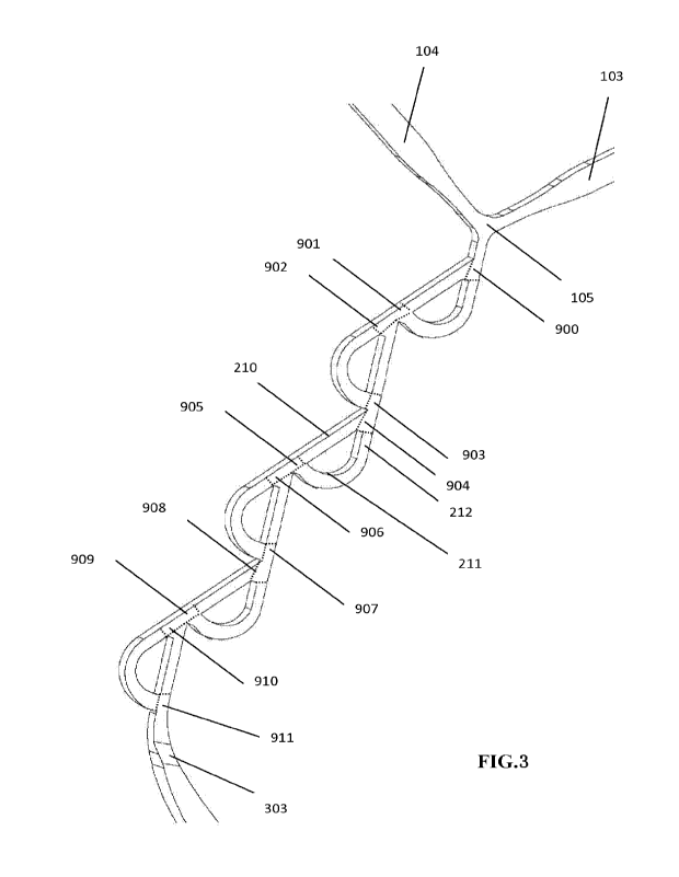
channels. As shown in FIG. 3, when there are six mixing units, in the
converging regions 900,
CA 03178413 2022- 11- 9
WO 2021/227544
PCT/CN2021/071253
902, 904, 906, 908, and 910, liquid is diverted or the mixed liquid is
diverted, and in the
converging regions 901, 903, 905, 907, 909, and 911, the liquid is merged,
converged, or mixed.
In some embodiments, the first channel 702 is a rectilinear channel and the
second channel
701 is a curvilinear channel, but the two channels are in a converging region
at the same location.
As used herein, the term "a converging region at the same location" means that
the inlets and
outlets of the two channels are in substantially the same position without
being separated by a
significant distance, and it will also be understood that the inlets of the
two channels are in the
same position, allowing liquid from the converging region to enter both the
first channel 702 and
the second channel 701 at substantially the same time. For example, the liquid
inlet 107 of the
first channel and the liquid inlet 108 of the second channel are both in fluid
communication with
the converging region where the liquid from the converging region 900 flows
into the first and
second channels, respectively. Flow into the first and second channels,
respectively, occurs
almost simultaneously. In this way, the fluid can exhibit different flow
characteristics in different
channels, such as different flow paths of the fluid, different flow
resistances, different flow rates,
ease of fluidity, etc. For example, the flow path in the first channel may be
shorter than that in
the second channel, or the flow resistance of the fluid flowing in the first
channel may be less
than the flow resistance of the fluid flowing in the second channel.
Therefore, in order to achieve
the flow characteristics of the fluids of the different channels, the first
channel 702 can be a
rectilinear channel and the second channel includes a curvilinear channel 111,
such that the fluids
have different flow characteristics in the two channels. In some embodiments,
a rectilinear initial
segment 110 in communication with or having a liquid inlet 108 is included in
the upstream sides
of the curvilinear channel 111 in the second channel. As such, one portion of
the fluid or mixed
fluid from the converging region 900 flows in the rectilinear channel 702 and
the other portion
enters the curvilinear channel 701 to flow, but the rectilinear initial
segment is connected to the
curvilinear channel. The fluids from the converging region enter the
respective channels at
substantially the same flow rate, but the characteristics of the flow rate is
substantially differed
most by a portion of the curvilinear channel. Clogging and jamming of the
fluid at a converging
region, and the design is particularly effective for particularly viscous
fluids. As shown in FIG 4,
arrows 109 and 123 illustrate a flow pattern of the fluid in the rectilinear
channel 702, and
arrows 110 and 111 illustrate a flow pattern of the fluid in the second
channel 701. At an outlet of
the two channels 701 and 702, a converging region 901 where the liquid from
the two channels is
converged and mixed. Then the liquid flows to the next mixing unit.
CA 03178413 2022- 11- 9
WO 2021/227544
PCT/CN2021/071253
21
In some embodiments, the mixer further includes a second mixing unit connected
to the
first mixing unit, wherein the second mixing unit has a same physical
structure as that of the first
mixing unit, but is connected in a manner or has a connection angle different
from that of the
first mixing unit. The second mixing unit includes a third channel 117 and a
fourth channel 116,
wherein the third channel includes a curvilinear channel and the fourth
channel includes a
rectilinear channel. Similarly, the third channel has a third fluid inlet 115
and a third fluid outlet
118, the fourth channel also has a fourth fluid inlet 114 and a fourth fluid
outlet 119, the inlets of
the two channels are connected to a converging region 902 and the outlets of
the two channels
are connected to a converging region 903. In some embodiments, for ease of
illustration, the
converging region 902 may be referred to as a third converging region, the
converging region
903 may be referred to as a fourth converging region, a converging region 900
may be referred to
as a first converging region, and a converging region 901 may be referred to
as a second
converging region. In some embodiments, an initial channel 117 of the second
mixing unit is
located on a same line with the rectilinear channel 702 of the first mixing
unit, it is understood
that the initial channel 117 in the third channel 118 of the second mixing
unit is an extended
segment in a rectilinear direction of the rectilinear channel 702. In some
embodiments, the inlet
114 of the rectilinear channel of the second unit is on a same side of the
channel as the outlet 112
of the curvilinear channel of the first channel. Alternatively, in some
embodiments, the inlet 114
of the rectilinear channel of the second unit is positioned or arranged
adjacent to the outlet 112 of
the curvilinear channel of the first channel. In some embodiments, the inlet
115 of the curvilinear
channel of the second mixing unit and the outlet 113 of the rectilinear
channel of the first mixing
unit are located on the same line, or disposed opposite.
In some embodiments, a rectilinear channel of each of the mixing units is
disposed by an
acute angle to an initial channel of the other curvilinear channel, wherein
the degree of such
angle is less than 900, such as 85 , 70 , 75 , 60 , 65 , 50 , 55 , 45 , 40 ,
30 , 35 , 20 , 25 , or
.
FIG. 4 is a schematic diagram showing the positional relationship structure of
two identical
mixing units. FIG. 3 is a schematic diagram showing an arrangement structure
of six mixing
units of the same structure. As can be seen from FIG. 4 and 3, the arrangement
is regular, and
according to the combination of the first mixing unit and the second mixing
unit described in
FIG. 4, a third mixing unit is provided below the second mixing unit, the
third mixing unit being
connected to the second mixing unit in the same or substantially the same
manner in which the
CA 03178413 2022- 11- 9
WO 2021/227544
PCT/CN2021/071253
22
second mixing unit is connected to the first mixing unit. Specifically, as
shown in FIG. 3, the
third mixing unit is located in the downstream of the second mixing unit, and
the second mixing
unit is located in the downstream of the first mixing unit. The third mixing
unit includes a
rectilinear channel 210 and a curvilinear channel 211, meanwhile, the
curvilinear channel is
connected upstream to a section of a rectilinear channel 212. Similarly, the
rectilinear channel
can be seen as an extended channel of the rectilinear channel 116 of the
second mixing unit, and
the third mixing unit also includes a converging region 904 where fluids from
the second mixing
unit are diverted, and a converging region 905 where fluids from the third
mixing unit are
converged and mixed. From this point of view, if the rectilinear channel 116
of the second
mixing unit is taken as a reference, a curvilinear channel 701 of the first
mixing unit is located to
the right side of the rectilinear channel and the curvilinear channel 118 of
the second mixing unit
is located to the left side of the rectilinear channel 116. Alternatively, the
rectilinear path 702 of
the first mixing unit and the rectilinear path of the third mixing unit are
relatively parallel and
form an angle with the rectilinear path 116 of the second mixing unit, the
degrees of the angle
can be greater than 90 , such as 95 , 98 , 100 , 105 , 110 , 115 . 120 , 125 ,
130 , 135 , 140 ,
145 , 160 , 170 , etc.
The two different fluids are continuously diverted, mixed, diverted, mixed and
diverted in
the mixing unit, such that the nanoparticle is prepared. This is similar to
microfluidic droplet
preparation techniques in that the two fluids converge at a convergence to
form water-in-oil or
oil-in-water droplets by shear forces of the liquid. Nanoparticle or particle
is prepared according
to the present invention, which may also be liposome-encapsulated nucleic
acid, or
liposome-encapsulated core stnictures, which are analogous structures formed
by nucleic acids
and polymers. Such a substance may be a material of the core structure and a
material of the
shell structure as described in Chinese Patent Application No. 20188001680.5.
All Embodiments
in this application are intended to be part of particular embodiments of the
present invention.
This regular connection, as can be seen from FIG. 3, includes an arrangement
of the
curvilinear channels of the first mixing unit opposite the curvilinear
channels of the second
mixing unit and the connection between the mixing units are free. FIG. 3 is
merely one preferred
implementation achieving a preparation of a nanoparticle.
Here, it means that all repeated mixing unit structures are identical, but the
way they are
connected is set regularly, but other ways of connection are not limited.
A structural arrangement of the mixing unit includes: the mixing unit includes
two channels,
CA 03178413 2022- 11- 9
WO 2021/227544
PCT/CN2021/071253
23
wherein one channel is rectilinear, the other channel is curvilinear, the arc
of the curved line is
included, and the relative relationship between the curved line and the
rectilinear channel is
included, such that the external shape of the integrally formed unit further
includes a change of
the size and the shape of the area at the inlet converging region and the
outlet converging region
of the two channels, a change in one of these factors, such as the depth and
width of the channel,
or the size of the cross-sectional area of the channel, may be considered a
different mixing
element. If there is a plurality of mixing regions, it is preferred that the
structure of each mixing
region is the same, only the permutation and combination are different, but it
is also possible that
the structure of each mixing region is different. For example, referring to
FIG. 4, there are two
mixing units having the same structure but different manners of connection or
combination. Of
course, it is also possible that mixing units of different structures are
connected in the same
manner. For example, the structure of the first mixing unit is the same as
that illustrated in FIG. 4,
but the structure of the second mixing unit may be different from that of the
first mixing unit,
one or more of the characteristics such as length, width, depth, cross-
sectional area, size of the
inlet, size of the outlet, curvature of the curved portion of the curvilinear
channel, or degree of
curvature, a length of the initial rectilinear channel is different from that
of the first mixing unit.
In some embodiments, the first and second channels of the first mixing unit
are each
connected head to end, respectively, which means that the first and second
channels are
connected head to head and end to end, respectively. Such connections are not
communications,
but are connections of different converging regions to achieve liquid
diversions at the head,
merging or convergence of liquids at the tail
Accordingly, the present invention provides a mixer including N mixing units,
wherein each
of the mixing units includes a rectilinear channel and a curvilinear channel,
each of the mixing
units includes a rectilinear fluid inlet and a rectilinear fluid outlet, a
fluid inlet and a fluid outlet
of the curvilinear channel, wherein N is a natural integer equal to or greater
than 1. In some
embodiments, the fluid inlet of the rectilinear channel and a stereoscopic
inlet of the curvilinear
channel communicate with the converging region to divert fluids at the
converging region, and
the fluid outlet of the rectilinear channel and a stereoscopic outlet of the
curvilinear channel
communicate with the converging region to mix or converge or merge the fluids
from the two
channels.
Therefore, the present invention provides a mixer including N+1 mixing units,
the Nth
mixing unit includes an a th rectilinear channel and an a+lth curvilinear
channel, the ath rectilinear
CA 03178413 2022- 11- 9
WO 2021/227544
PCT/CN2021/071253
24
channel includes an ath fluid inlet and an ath fluid outlet, the a+lth
curvilinear channel includes an
a+lth inflow inlet and an a+lth fluid outlet, wherein N is a natural integer
equal to or greater than
1, and a is a natural number greater than or equal to 1. Alternatively, the
present invention
provides a mixer including N+1 mixing units, the Nth mixing unit includes an
ath rectilinear
channel and an a+ 1thcurvilinear channel, the ath rectilinear channel includes
an ath fluid inlet and
an ath fluid outlet, the a+lth curvilinear channel includes an a+lth inflow
inlet and an a+lth fluid
outlet, wherein N is a natural integer equal to or greater than 1, and a is a
natural number greater
than or equal to 1. In some embodiments, the length of the ath rectilinear
channel is less than the
a+lth curvilinear channel; alternatively, a path through which the fluid flows
in the ath linear
channel is smaller than a path through which the fluid flows in the a+lth
curvilinear channel.
In some embodiments, a fluid inlet of the ath rectilinear channel and a
stereoscopic inlet of
the curvilinear channel include the at converging region to divert fluids at
the converging region,
and the fluid outlet of the rectilinear channel and the stereoscopic outlet of
the curvilinear
channel include the a+lth converging region to mix or converge or merge the
fluids from the two
channels.
In some embodiments, the N+lth mixing unit also includes an a+2-th rectilinear
channel
including an a+2th fluid inlet and an a+2th fluid outlet, and an a+3 th
curvilinear channel including
an a+3 th fluid inlet and an a+3th fluid outlet. In some embodiments, the
fluid inlet of the a+2th
rectilinear channel and the fluid inlet of the a+3th curvilinear channel
includes an a+2th
converging region to divert fluids at the converging region; a fluid outlet in
the a+2 th rectilinear
channel and a fluid outlet in the a+3 th curvilinear channel includes an a+3
th converging region to
mix or converge or merge the fluids from the two channels.
In some embodiments, the a thfluid outlet is disposed opposite to the a+3t11
fluid inlet. In
some embodiments, the a+ th fluid outlet is disposed adjacent to an a+2th
fluid inlet, or on a same
side of a channel.
The mixer composed of a plurality of mixing units in communication with each
other
provided by the present invention can be referred to as a separating and
recombination mixer.
The separating and recombination mixer refers to more than two channels (such
as a first channel
and a second channel) of each mixing unit, wherein each of the mixing units is
divided into more
than two channels which are connected in parallel and then recombined into one
channel. By
recombining a channel, it is possible to achieve at least a short converge in
the converging
region, which means that a length of the merged channels is relatively short,
essentially in the
CA 03178413 2022- 11- 9
WO 2021/227544
PCT/CN2021/071253
same concept as in the converging region, and fluid diversion and converge in
the converging
region can take place almost simultaneously or at intervals. For example, as
shown in FIG. 4, the
converging region 901 is a region where two outlet fluids of the first mixing
units are mixed or
converged, the other converging region 902 is a region where a mixed fluid is
rediverted into the
channels of the second mixing unit. There is no strict demarcation between the
converging
region 901 and the converging region 902, illustrated by way of example only
for ease of
description, although the two converging regions may also be collectively
referred to as a
converging region to mix and divert fluids that may or may not occur
simultaneously.
Further, the curvilinear channel is formed by combining semi-circular arcs or
arcs with
different circle centers. Of course, the rectilinear path shown herein is
merely rectilinear in the
general sense and does not require the rectilinear path seen by precision
equipment instruments,
as compared with a curvilinear path. A curve is a concept as compared with a
straight line.
In some embodiments, as shown in FIG. 4 or 3, the two channels forming the
mixing unit
form a "D" shape or "B" shape, and this mixing unit can be formed by two "D"
letters, and the
letter "B" includes two mixing units. The mixing unit can be combinations in
any other form.
Through a large number of experiments, the research group has found that when
the
separating recombination mixing conduit is used for forming the nanoparticle,
the mixing
efficiency is obviously higher than that of mixing conduits of other shapes,
and the liquid in the
conduit is subjected to mixing, diverting, remixing and rediyerting a
plurality of times, such that
the mixing effect is higher; however, due to the fact that the existing
separating and
recombination mixing conduits are mostly circular arc rings or fan-shaped and
the like, the
structure is complex, when used for generating a microparticle, the conduits
have a high flow
resistance, ease in blockage, and still unsatisfactory mixing effect.
According to the present
invention, the structure creative design and improvement are carried out on
the basis of the
existing separating and recombination mixing conduits, such that one path is
guaranteed to be
rectilinear, the flow resistance is reduced as much as possible, and the other
path is semi-circular
arc-shaped, such that the mixing effect is greatly improved.
In some embodiments, the semi-circular arc-shaped second channel has a
rectilinear
segment, and it can be seen that the second channel is not regularly semi-
circular arc-shaped, but
approximately semi-circular arc-shaped through creative design, which can help
to reduce the
flow resistance and improve the mixing effect.
CA 03178413 2022- 11- 9
WO 2021/227544
PCT/CN2021/071253
26
Further, a length of the initial segment is less than or equal to 1/3 of a
length of the second
channel. The rectilinear segment cannot be too long, otherwise the mixing
effect will be affected
and therefore needs to be controlled within 1/3 of a length of the second
channel. A "curvilinear
channel" refers to a channel included in the second channel, which is
curvilinear, can be either a
curve with continuous arcs or a curve with a fixed arc, such that the curve
can be, for example, a
serpentine curve or the shape of some of the channels as shown in FIG. 15. In
FIG. 15, the
rectilinear shape is related to a rectilinear channel, and the curvilinear
shape is related to a
curvilinear channel. The curvilinear channel herein refers to that part of the
second path is
curvilinear, of course it can be understood that the second path itself is
totally or wholly
curvilinear with respect to the rectilinear path. Correspondingly, a
rectilinear channel does not
mean that all channels are rectilinear, but may include curvilinear channels
in the rectilinear
channel, such that the length can be reduced. In general, fluids with
different fluid flow
characteristics, such as velocity, path length of flow, volume of flow per
unit time, etc. are
allowed to flow in the two channels.
Further, the mixer includes two or more mixing units, and each of the mixing
units is
connected head to end; two adjacent mixing units are a mixing unit A and a
mixing unit B, the
second channel of the mixing unit A is positioned on a right side of the first
channel, and the
second channel of the mixing unit B is positioned on a left side of the first
channel.
Each of the mixing units is connected head to end, which means that the head
of the mixing
unit A is connected to the end of the mixing unit B, and the mixing units are
connected together
in series. However, the semi-circular arc directions of the adjacent mixing
units A and B are
opposite, such that the fluids flow in the same path during separation and
recombination, but the
flow directions are opposite, the turbulences and the vortexes generated are
also opposite, and
therefore the impact force encountered is changed regularly, such that the
fluids are mixed more
uniformly and stably.
Further, all channels have the same width. Because the widths of the channels
are consistent
and are not changed obviously, the fluid is not easy to be blocked by foreign
matters in the
mixing process. In some embodiments, the size or cross-sectional area or a
channel section of the
mixing unit is the same, such that such a microparticle channel can be
manufactured more easily,
simply by changing the shape of the channel. The depth, width, or cross-
sectional area, etc.
herein may allow the two channels to be consistent, but the alternatives that
do not maintain
consistency are not precluded.
CA 03178413 2022- 11- 9
WO 2021/227544
PCT/CN2021/071253
27
Further, the first channel (rectilinear channel) of each of the mixing units
is in rectilinear
communication with an initial segment of the second channel (including a
curvilinear channel) of
the next mixing unit. This further helps to reduce the flow resistance and
improve the mixing
effect.
Furthermore, the channel section of the mixer provided by the present
invention is
rectangular, and lengths and widths of the sections of all channels are
uniform. The section of a
channel of the mixer can be made into various shapes as required, such as a
circle, a semicircle, a
square, a rectangle, a triangle, a trapezoid and the like, and the channel
section of the mixer is
preferably a rectangle or a square for convenience of manufacture.
Further, the mixer includes six mixing units connected in series in the same
manner as the
first mixing unit and the second mixing unit. Further enhancement of the
mixing effect can also
be achieved by a series connection of more mixing units.
It can be proved by multiple experiments carried out by a research group that
the mixing
conduit containing 6 mixing units for preparing the nanoparticle can
completely meet the
requirement for mixing effect of preparing the nanoparticle. The invention
therefore preferably
employs a mixer including six mixing units. This is merely a preferred
solution, and does not
mean that a single mixing unit cannot be implemented, and that a flow path can
be extended, and
the mixer may consist of two or more mixing units connected in series.
Further, it is also possible to carry out a series connection of a plurality
of mixers to
improve a mixing effect according to a need for preparing a product. Multiple
mixers can also be
connected in series or in parallel into the microfluidic hybrid chip
cartridge. In certain
embodiments, a second mixer is included. Other inlet connections may also be
added to support
the function of additional mixers. In one Example, a plurality of mixers may
be included in the
chip.
In still other embodiments, a third inlet connection is included and a second
mixer is
included to dilute the mixed solution produced by the first mixer by mixing
the diluted solution
provided via the third inlet connector.
"Incorporated ...in its entirety" in the mixer is incorporated into the chip
in its entirety
means that the mixer structure cannot be easily removed from the chip. For
example, provided
that the chip can only be opened with a tool, such as a screwdriver for
loosening set screws, in
order to expose the mixer structure, the mixer is incorporated into the chip
in its entirety.
Additionally, provided that the chip is sealed to be closed such that the
mixer can only be
CA 03178413 2022- 11- 9
WO 2021/227544
PCT/CN2021/071253
28
removed by breaking same, the mixer can be incorporated into the chip in its
entirety. In still
other embodiments, provided that the mixer is physically attached or part of
the chip (e.g., the
microfluidic hybrid chip cartridge is of unitary configuration or has been
permanently attached
using adhesives, solvent soldering, or other techniques), the mixer can be
incorporated into the
chip in its entirety. The overall configuration described above is not
considered to be
incorporated into the chip because the mixer is part of the chip, which
provides functions other
than microfluidic flow (e.g., structural support).
In yet another example, incorporation in its entirety means that the
microfluidic hybrid chip
cartridge cannot be disassembled and reassembled together. For example, the
mixer cannot be
removed from the chip and then replaced and sealed.
Cartridge material and configuration
The chip and microfluidic structure are formed from materials capable of
forming the
desired shape and having the desired physical characteristics. The material of
the microfluidic
structure is capable of forming the required microscale mixing channels and of
withstanding the
pressure exerted during mixing in the microfluidic structure. The material of
the chip is
sufficiently rigid that it will protect and support the microfluidic
structures within the chip.
In one Example, the microfluidic structure and chip are formed from different
materials. In
yet another example, the microfluidic structure and the chip are formed from
the same material.
In yet another example, the microfluidic structure and the chip are integrally
formed.
In one Example, the chip is free of metal. In yet another example, the chip
may contain
some metal, but at least 90% by weight of the chip is a polymer. In one
Example, the chip is free
of metal. In yet another example, the chip may contain some metal, but at
least 99% by weight of
the chip is a polymer.
In one Example, the chip includes a polymer selected from the group consisting
of
polypropylene, polycarbonate, COC, COP, polystyrene, nylon, acrylic polymers,
HPDE, LPDE,
and other polyolefins.
In one Example, the chip does not include metal on the outer surface. It can
be
contemplated in the embodiments that magnets or other metal-containing
elements may be
present within the chip, but not on the outer surface.
In yet another example, the first inlet connector and the second inlet
connector are formed
from a polymer. It is preferred in certain embodiments that the inlet
connector be formed from a
relatively soft polymeric material, particularly where tapered connectors or
Luer connectors are
CA 03178413 2022- 11- 9
WO 2021/227544
PCT/CN2021/071253
29
used. A softer polymer will improve the secondary manufacturing error of the
inlet and allow the
formation of a liquid-tight connection. A more rigid polymer will not allow
the fault tolerance
feature described above. In this aspect, in one Example, the first inlet
connector includes a
polymer having a Young's modulus of 500 MPa to 3500 MPa. In one Example, the
first inlet
connector includes a polymer having a Young's modulus of 2000 MPa to 3000 MPa.
In one Example, the chip includes a metal selected from the group consisting
of aluminum
and steel. As described above, in certain embodiments, a small amount of metal
can be
incorporated into the chip.
In one Example, the microfluidic structure is inseparable from the chip. In
such
embodiments, the microfluidic structure is attached (e.g., welded or attached)
to at least a portion
of the carrier. In one Example, the microfluidic hybrid chip cartridge is of
unitary configuration,
wherein the chip and the microfluidic structure are formed from the same
material. In yet another
example, the microfluidic hybrid chip cartridge consists of at least two
portions, such as a
connecting portion and a top plate, wherein the microfluidic structure
incorporates one of the two
portions. That is, the microfluidic structure is attached (e.g., bonded or
soldered) to a portion of
the microfluidic hybrid chip cartridge that performs an additional function
beyond providing
microfluidic elements. In one Example, the microfluidic structure is connected
to the top plate.
In yet another example, the microfluidic structure and the top plate are
monolithic and formed
from the same material. In yet another example, the microfluidic structure is
of unitary
configuration with one of the two parts.
In one Example, the chip surrounds the microfluidic structure. As used herein,
the term
"surround" refers to a chip surrounding a substantial portion of a surface
area of the mixer. Most
importantly, the chip facilitates a fluid-tight seal with the microfluidic
structure and provides a
rigid chamber that allows manipulation of the microfluidic hybrid chip
cartridge. In yet another
example, the chip completely surrounds the microfluidic structure, which means
that no surface
area of the microfluidic structure is exposed outside the carrier. The
embodiments are illustrated in
FTGs. 1A-3.
In one Example, the first portion and the second portion are joined together
to surround the
microfluidic structure.
In one Example, at least 90% by weight of the first portion is a polymer. In
this Example,
the first portion includes an inlet connector and an outlet opening.
In one Example, the first portion or the second portion includes a
microfluidic structure In
such embodiments, the microfluidic structure is attached to or integrated with
the first or second
CA 03178413 2022- 11- 9
WO 2021/227544
PCT/CN2021/071253
portion of the chip.
Fluid source
Fluids or solution reservoir are selected to make it possible to connect
directly to the
microfluidic hybrid chip cartridge. In one Example, the fluid reservoir is a
disposable syringe. In
yet another example, the fluid reservoir is a pre-filled syringe. Both the
fluid and the reservoir
may be sterile to produce a sterile nanoparticle. The system contains an
apparatus by which a
fluid flows from the reservoir and through the cartridge at a specified flow
rate. In one Example
of the system, a reservoir is pressurized to flow a fluid, such that the first
and second fluids enter
the cartridge (the fluids enter a microfluidic structure and its channels
through an inlet).
Embodiments of pressurizing devices include, but are not limited to,
rectilinear actuators and
inert gases. In one Example, each reservoir is independently pressurized. In
one Example, two or
more reservoirs are pressurized by the same source, while different flow rates
are obtained by
varying dimensions of the fluid channels. Differential flow rates may be made
possible by
different pressure drops, differential channel impedance, or a combination
thereof applied to the
inlet stream across the fluid channels. Different flow rates can be obtained
by varying the
different channel impedance of a height, a width, a length or surface
characteristics of the
channel. Different flow rates can be obtained by using or considering fluid
surface tension,
viscosity, and other surface characteristics of the fluid in one or more first
streams and one or
more second streams. Container pressurization may be controlled by a computer
or
microcontroller.
In certain embodiments, the system further includes means for full or partial
system purging
to minimize waste volume. After or during preparation of particles, purging
may be
accomplished by flowing a gas or liquid through a linker and a microfluidic
structure. Gases
such as air, nitrogen, argon and the like may be used. Liquids may be used
including water,
aqueous buffers, ethanol, oil, or any other liquid.
Fixing mechanism
In one Example, the microfluidic hybrid chip cartridge further includes a
securing
mechanism configured to secure a microfluidic hybrid chip cartridge to a
holder. In one Example,
the holder is a device configured to arrange the microfluidic hybrid chip
cartridge relative to a
fluid source (e.g., a syringe) and facilitate connection therebetween.
Asepsis
CA 03178413 2022- 11- 9
WO 2021/227544
PCT/CN2021/071253
31
Sterile cartridges are necessary for certain applications and provide a
convenient workflow
for a user to formulate a sterile nanoparticle directly without further
filtration or processing. The
above workflow minimizes substance loss associated with further sterilization
steps. In one
Example, individual components of a cartridge are sterilized before assembly.
Representative
sterilization methods include steam autoclaves, dry heating, chemical
sterilization (i.e., sodium
hydroxide or ethylene oxide), 7 radiation, gases, and combinations thereof. In
a particular
embodiment, a microfluidic structure, an inlet connector, an outlet connector,
and any other fluid
contacting components are formed from a material compatible with 7 radiation
and sterilized by
such means. Materials compatible with y radiation are those capable of being
irradiated. For
example, polycarbonates, cyclic olefin polymers, cyclic olefin copolymers,
polypropylene, and
high and low density polyethylene. Materials that cannot be irradiated include
polyamide,
polytetrafluoroethylene, and any metal. In yet another example, a cartridge is
sterilized after
assembly.
In one Example, the cartridge is sterilizable. As used herein, the term
"sterilizable" means
that the cartridge is formed from a material compatible with known
sterilization methods, as
previously described. In one Example, the cartridge is specifically
sterilizable by y radiation. In
yet another example, the cartridge is formed from a polymer selected from the
group consisting
of polypropylene, polycarbonate, cyclic olefin polymers, cyclic olefin
copolymers, high density
polyethylene, low density polyethylene, and combinations thereof. In yet
another example, the
cartridge does not include polyamide, polytetrafluoroethylene, or any metal.
In one Example, a microfluidic hybrid chip cartridge is sterile
In one Example, a microfluidic hybrid chip cartridge includes a sterile fluid
path from a first
inlet connector and a second inlet connector, through a microfluidic
structure, and to an outlet
opening. The sterile fluid path described above allows mixing in a sterile
environment. Since the
inlet connector and the outlet opening are also sterile, a sterile connection
can easily be made
possible.
In yet another aspect, a sterile package filled with sterile contents is
provided. In one
Example, the sterile package including a microfluidic cartridge according to
any one of the
embodiments disclosed herein is in a sterile state and sealed within the
sterile package. The
sterile package is defined by a housing containing sterile contents. The
housing in one Example
is a bag. By providing a microfluidic hybrid chip cartridge that is sterile
and sealed within a
sterile package, an end user can easily carry out sterile microfluidic mixing
with the cartridge:
CA 03178413 2022- 11- 9
WO 2021/227544
PCT/CN2021/071253
32
the sterile package is opened in a sterile environment and used for mixing
without any
preparation. Sterilization is not required for any sterile inlet connector or
fluid path.
In one Example, the sterile package further includes a first sterile syringe
configured to
couple with the first inlet connector of the microfluidic cartridge. In this
Example, the sterile
package is a kit including a microfluidic cartridge and a sterile syringe
configured for use with
the microfluidic cartridge. In one Example, the sterile package further
includes a first solution in
a first sterile syringe.
In one Example, the first solution includes nucleic acid in a first solvent.
In yet another
example, the first solution is configured to form a lipid nanoparticle.
In one Example, the sterile package further includes a second sterile syringe
configured to
couple with the second inlet connector of the microfluidic cartridge.
In one Example, the sterile package further includes a second solution in a
second sterile
syringe.
In one Example, the second solution includes a lipid particle-forming material
in a second
solvent. The second solution can be combined with a first solution including
nucleic acid in a
first solvent to form a lipid nanoparticle solution via a microfluidic
cartridge.
In one Example, the sterile package further includes a sterile container
configured to couple
with an outlet opening of the microfluidic cartridge via an outlet opening
connector.
In one Example, the sterile contents are disposable.
Nanoparticle
The nanoparticle described herein is a homogeneous particle including more
than one
component (e.g., lipid, polymer, etc.) that is used to encapsulate a
therapeutic substance and has
a minimum dimension of less than 250 nanometers. A nanoparticle includes, but
is not limited to,
lipid nanoparticle and polymer nanoparticle.
Lipid nanoparticle
In one Example, a lipid nanoparticle includes: (a) a core; and (b) a shell
surrounding the
core, wherein the shell includes a phospholipid. Of course, it can also be a
lipid-encapsulated
nucleic acid substance.
In one Example, the core includes a lipid (e.g., a fatty acid triglyceride)
and is a solid. In yet
another example, the core is a liquid (e.g., aqueous) and the particle is a
vesicle such as a
liposome. In one Example, the shell surrounding the core is single-layered.
CA 03178413 2022- 11- 9
WO 2021/227544
PCT/CN2021/071253
33
As described above, in one Example, the lipid core includes a fatty acid
triglyceride. A
suitable fatty acid triglyceride includes a C8-C20 fatty acid triglyceride. In
one Example, the fatty
acid triglyceride is an oleic triglyceride.
The lipid nanoparticle includes a shell including a phospholipid, the shell
surrounding a
core. Suitable phospholipids include diacylphosphatidylcholine,
diacylphosphatidylethanolamine,
ceramide, sphingomyelin, dihydrosphingomyelin, cephalin, and cerebroside. In
one Example, the
phospholipid is a Cs-C20 fatty acid diacylphosphatidylcholine. A
representative phospholipid is
1-palmitoy1-2-oleoylphosphatidylcholine (POPC).
In certain embodiments, a ratio of phospholipid to fatty acid triglyceride is
from 20 : 80
(mol : mol) to 60 : 40 (mol : mol). Preferably, triglycerides are present in a
ratio of greater than
40% and less than 80%.
In certain embodiments, the nanoparticle further includes a sterol.
Representative sterols
include cholesterol. In one Example, the ratio of phospholipid to cholesterol
is 55 : 45 (mol :
mol). In a representative Example, the nanoparticle includes 55-100% of POPC
and up to 10 mol%
of PEG-lipid.
In other embodiments, the lipid nanoparticle of the present disclosure may
include one or
more other lipids, including phosphoglycerides, representative embodiments of
which include
phosphati dylcholine, phosphati dylethanolamine, phosphatidylserine,
phosphatidylinositol,
phosphati di c acid, palmitoyl oleoylphosphatidylcholine,
lysylphosphati dylcholine,
ly sophosphatidylethanolamine, dipalmitoylphosphatidylcholine, di
oleoylphosphati dylcholine,
di stearoyl phosphati dylcholine, and di ol eoylphosphatidyl choli ne . Other
compounds lacking
phosphorus such as sphingolipids and glycosphingolipids are useful.
Triacylglycerols are also
useful.
A representative nanoparticle of the present disclosure has a diameter of
about 10 to about
100 nm. A lower limit of the diameter is about 10 to about 15 nm.
The lipid nanoparticle of the present disclosure with a limited size can
include one or more
therapeutic and/or diagnostic agents. These agents are generally contained
within the particle
core. The nanoparticle of the present disclosure can include a wide variety of
therapeutic and/or
diagnostic agents.
Suitable therapeutic agents include chemotherapeutic agents (i.e.,
antineoplastic agents),
anesthetics, 13-adrenergic blockers, antihypertensives, antidepressants,
anticonvulsants,
antiemetics, antihistamines, antiarrhythmics, and antimalarial s.
CA 03178413 2022- 11- 9
WO 2021/227544
PCT/CN2021/071253
34
Representative antineoplastic agents include doxorubicin, daunorubicin,
mitomycin,
bleomycin, streptozocin, vinblastine, vincristine, nitrogen mustard,
hydrochloride, melphalan,
cyclophosphamide, triethylenethiophosphoramide, carmustine, lomustine,
semustine,
fluorouracil, hydroxyurea, thioguanine, cytarabine, floxuridine, amidoximine,
cisplatin,
procarbazine, vinorelbine, ciprofloxacin, norfloxacin, paclitaxel, docetaxel,
etoposide,
bexarotene, teniposi de, tretinoin, isotretinoin, sirolimus, fulvestrant,
yalrubicin, vindesine,
leucovorin, irinotecan, capecitabine, gemcitabine, mitoxantrone hydrochloride,
oxaliplatin,
doxorubicin, methotrexate, carboplatin, estramustine, and pharmaceutically
acceptable salts
thereof.
In yet another example, a lipid nanoparticle is a nucleic acid-lipid
nanoparticle.
The nucleic acid-lipid nanoparticle refers to a lipid nanoparticle containing
a nucleic acid.
The lipid nanoparticle includes one or more cationic lipids, one or more
second lipids, and one or
more nucleic acids.
The lipid nanoparticle includes a cationic lipid. A cationic lipid refers to a
lipid that is a
cation or becomes a cation (protonated) as the pH decreases below an ionizable
group pK of the
lipid, but gradually becomes more neutral at higher pH values. At a pH value
below pK, a lipid
can then bind to a negatively charged nucleic acid (e.g., oligonucleotide).
The cationic lipid
includes a zwitterionic lipid that is positively charged when the pH
decreases.
The cationic lipid refers to any of a number of lipid species that carry a net
positive charge
at a selective pH, such as a physiological pH. Such lipid includes, but is not
limited to,
N , N -di ol eyl-N,N-dim ethyl amm onium chloride (DO DAC); N-(2,3 -di ol eyl
oxy) propy1)-N,
N,N-trimethylammonium chloride (DOTMA); N,N-distearyl-N,N-dimethylammonium
bromide
(DDAB); N-(2,3 -di ol e oyl oxy) propy1)-N,N,N-tri methyl amm onium chloride
(DO TAP);
3 -(N-(N',1\11-dimethyl ami noethane)-carb am oyl) cholesterol (DC-Chol)
and
N-( 1 ,2-dimyri styl oxyprop an-3 -y1)-N,N-dimethyl -N-hy droxy ethyl ammonium
bromide (DMRIE).
Additionally, there are many commercial formulations of cationic lipids that
can be used in the
present disclosure. These include, for example, (a commercially available
cationic liposome
containing DOTMA and 1,2-dioleoyl-sn-3-phosphoethanolamine (DOPE) from
GlBCO/BRL,
Grand Island, NY); (a commercially available cationic liposome containing N-(1-
(2,3-dioleyloxy)
propy1)-N-(2-(spermidine carcartridgeamido) ethyl)-N,N-dimethylammonium
trifluoroacetate
(DOSPA) and (DOPE) from GIBCO/BRL); and (a commercially available cationic
lipid
containing dioctadecylamidoglycylcarcartridgeyspermine (DOGS) in ethanol from
Promega
CA 03178413 2022- 11- 9
WO 2021/227544
PCT/CN2021/071253
Corp., Madison, WI). The following lipids are cations and have a positive
charge at
physiological pH: DODAP, DODMA,
DMDMA,
1,2 -di ol efi nenyl oxy-N,N-dimethyl aminop rop ane
(DLinDMA),
1,2 -dillenenyloxy -N ,N -dimethylaminopropane (DLenDMA).
In one Example, the cationic lipid is an amino lipid. Aminolipids suitable for
use in the
disclosure include those described in WO 2009/096558, which is incorporated
herein by
reference in its entirety. Representative
amino lipids include
1,2-di ol eyli deneoxy-3 -(dimethylamino) acetoxypropane
(DLin-DAC),
1,2 -di ol eyli deneoxy-3 -morpholinopropane
(DLin-MA),
1,2-di ol eyli dene-3 -dimethylaminopropane
(DLinDAP),
1,2-di ol eyli denethi o-3 -dimethylaminopropane
(DLin- S-DMA),
1-linoleoy1-2-linoleyyloxy-3 -dimethylaminopropane
(DLin-2-DMAP),
1,2-di ol eyli deneoxy-3 -trimethylaminopropane chloride
(DLin-TMA. Cl),
1,2-dioley1-3-trimethylaminopropane chloride salt (DLin-
released Cl),
1,2-di ol eyli deneoxy-3 -(N-methylpiperazino) propane
(DLin-MPZ),
3 -(N,N-di oleylideneamino)-1,2-propanediol
(DLINAP),
3 -(N,N-di oleylideneamino)-1,2-propanediol
(DOAP),
1,2-di ol eyl i deneox o-3 -(2-N,N-dimethyl amino) ethoxypropane
(DLin-EG-DMA), and
2,2 -di ol eyli dene-4-dimethylaminomethyl- [1,3 ]-dioxolane (DLin-K-DMA).
Suitable amino lipids include those having the formula.
R51
R2
¨(C1-i2)q¨cs.
Ry
R3 Z m
wherein Rl and R2 are the same or different and are independently optionally
substituted
C10-C24 alkyl, optionally substituted C10-C24 alkenyl, optionally substituted
C10-C24 alkynyl, or
optionally substituted C10-C24 acyl; R3 and R4 are the same or different and
are independently
optionally substituted C1-C6 alkyl, optionally substituted C2-C6 alkenyl, or
optionally substituted
C2-C6 alkynyl; or R3 and R4 may be joined to form an optionally substituted
heterocyclic ring
having 4 to 6 carbon atoms and 1 or 2 heteroatoms selected from nitrogen and
oxygen; le is
absent or present, and it is hydrogen or C1-C6 alkyl when present; m, n and p
are the same or
different and are independently 0 or 1, provided that m, n and p are not
simultaneously 0; q is 0,
1, 2, 3 or 4; and Y and Z are the same or different and are independently 0, S
or NH.
CA 03178413 2022- 11- 9
WO 2021/227544
PCT/CN2021/071253
36
In one Example, R1 and R2 are each a linoleyl, and an amino lipid is a
diolefinenyl amino
lipid. In one Example, the amino lipid is a dilinoleyl amino lipid.
Representative useful diolefinenylaminolipids have the formula:
(12 n
wherein n is 0, 1, 2, 3 or 4.
In one Example, the cationic lipid is DLin-K-DMA. In one Example, the cationic
lipid is
DLin-KC2-DMA (DLin-K-DMA described above, wherein n is 2).
In addition to those specifically described above, other suitable cationic
lipids include
cationic lipids which carry a net positive charge at about physiological pH:
N,N-di ol eyl-N,N-dimethyl ammonium chloride (DODAC);
N-(2,3 -di ol eyloxy)
propyl-N,N-N-triethylammonium chloride (DOTMA); N,N-distearyl-N,N-
dimethylammonium
bromide (DDAB); N-(2,3-dioleoyloxy) propy1)-N,N-trimethylammonium chloride
(DOTAP);
= 1,2 -di ol eyl oxy-3 -trim ethyl
aminoprop ane chloride salt (DO TAP Cl);
3f3-(N',N'-dimethylaminoethane) carbamoyl) cholesterol (DC-Chol), N-(1-(2,3-
dioleoyloxy)
propy1)-N-2-(sperminoylamido) ethyl)-N,N-dimethylammonium trifluoroacetate (DO
SPA),
dioctadecyl amidoglycylcarboxy spermine (DOGS), 1,2-dioleoy1-3-
dimethylammoniumpropane
(DODAP), N,N-dimethy1-2,3 -di ol eoyloxy) propyl amine
(DODMA), and
N-(1,2-dimyristoyloxypropan-3-y1)-N,N-dimethyl-N-hydroxyethylammonium
bromide
(DMRIE). Additionally, many commercial formulations of cationic lipids can be
used, such as
LIPOFECTIN (including DOTMA and DOPE available from GIBCO/BRL), and
UPOFECTAIVIINE (including DOSPA and DOPE available from GIBCO/BRL).
The cationic lipid is present in the lipid particle in an amount of about 30
to about 95 mole
percent. In one Example, the cationic lipid is present in the lipid particle
in an amount of about
30 to about 70 mole percent. In one Example, the cationic lipid is present in
the lipid particle in
an amount of about 40 to about 60 mole percent.
In one Example, the lipid particle includes one or more cationic lipids and
one or more
nucleic acids.
In certain embodiments, the lipid nanoparticle includes one or more second
lipids. Suitable
second lipids stabilize nanoparticle generation.
CA 03178413 2022- 11- 9
WO 2021/227544 PCT/CN2021/071253
37
Lipids refer to a class of organic compounds that are esters of fatty acids
and are
characterized by being insoluble in water but soluble in many organic
solvents. Lipids are
generally classified into at least three categories: (1) "simple lipids",
which include fats and oils
and waxes; (2) "compound lipids", which include phospholipids and glycolipids;
and (3)
"derivatized lipids" such as steroids.
Suitable stabilizing lipids include neutral lipids and anionic lipids.
A neutral lipid refers to any of a number of lipid species that exist in
uncharged or neutral
zwitterionic form at physiological pH. Representative neutral lipids include
diacylphosphatidylcholine, diacylphosphatidylethanol amine,
ceramide, sphingomyelin,
dihydrosphingomyelin, cephalin, and cerebroside.
Exemplary lipids include, for example, distearoylphosphatidylcholine (DSPC),
dioleoylphosphatidylcholine (DOPC),
dipalmitoylphosphatidylcholine (DPPC),
dioleoylphosphatidylglycerol (DOPG),
dipalmitoylphosphatidylglycerol (DPPG),
dioleoyl-phosphatidylethanolamine (DOPE), palmitoyl oleoylphosphatidylcholine
(POPC),
palmitoyl oleoyl-phosphatidylethanolamine (POPE) and dioleoyl-
phosphatidylethanolamine
4-(N-maleimidomethyl)-cyclohexane- 1 - carcartri dgeyl ate
(DOPE-mal),
dipalmitoylphosphatidylethanol amine (DPPE),
dimyristoylphosphatidylethanolamine (DMPE),
distearoyl-phosphatidylethanolamine (DSPE), 16-0-monomethyl PE, 16-0-dimethyl
PE,
18-1-trans PE, 1-stearoy1-2-oleoyl-phosphatidylethanolamine
(SOPE), and
1,2-dioleoyl-sn-glycero-3-phosphoethanolamine (trans DOPE).
In one Example, the neutral lipid is 1,2-di stearoyl-sn-glycero-3-
phosphocholine (DSPC).
An anionic lipid refers to any lipid that is negatively charged at
physiological pH. These
lipids include phosphatidylglycerol, cardiolipin, diacylphosphatidylserine,
diacylphosphatidylic
acid, N-dodecanoyl phosphatidylethanolamine, N-succinyl
phosphatidylethanolamine,
N-glutaryl phosphatidylethanolamine, lysyl phosphatidylglycerol, palmitoyl
oleoyl
phosphatidylglycerol (POPG), and other anionic modifying groups attached to
neutral lipids.
Other suitable lipids include glycolipids (e.g., monosialoganglioside GM1).
Other suitable
second lipids include sterols such as cholesterol
In certain embodiments, the second lipid is a polyethylene glycol-lipid.
Suitable
polyethylene glycol-lipids include PEG-modified phosphatidylethanol amine, PEG-
modified
phosphatidic acid, PEG-modified ceramide (e.g., PEG-CerC14 or PEG-CerC20), PEG-
modified
dialkylamine, PEG-modified diacylglycerol, and PEG-modified dialkylglycerol.
Representative
CA 03178413 2022- 11- 9
WO 2021/227544
PCT/CN2021/071253
38
polyethylene glycol-lipids include PEG-c-DOMG, PEG-c-DMA, and PEG-s-DMG. In
one
Example, the polyethylene glycol-lipid is N-(methoxypoly (ethylene glycol)
2000)
carbamoy1-1,2-dimyristyloxypropy1-3-amine (PEG-c-DMA). In one Example, the
polyethylene
glycol-lipid is PEG-c-DOMG).
In certain embodiments, the second lipid is present in the lipid particle in
an amount of
about 0.5 to about 10 mole percent. In one Example, the second lipid is
present in the lipid
particle in an amount of about 1 to about 5 mole percent. In one Example, the
second lipid is
present in the lipid particle in about 1 mole percent.
The lipid nanoparticle disclosed herein can be used for systemic or local
delivery of a
nucleic acid. As described herein, the nucleic acid is incorporated into the
lipid particle during
formation of same.
Of course, such nanoparticle may also be core-shell structured particle, if
the nucleic acid is
mixed with the polymer to form a core and then the liposome is encapsulated
outside the core
structure, or may be accomplished by the mixer of the present invention. The
nucleic acid and
polymer may be first formed into a microparticle structure by a mixer, and
then the microparticle
and lipid components may be formed into a microparticle structure by the
mixer. Such a
core-shell structure, e.g. all core materials and shell materials in a Patent
Application No.
201880001680.5 can be formed with the mixer of the present invention, all core-
constituting
materials and shell-forming materials of which are an implementation of the
present invention.
Nucleic acid
A nucleic acid includes any oligonucleotide or polynucleotide. A fragment
containing up to
50 nucleotides are generally referred to as an oligonucleotide, while a longer
fragment is referred
to as a polynucleotide. In a particular embodiment, the oligonucleotide
consists of 20-50
nucleotides in length. In the present invention, the polynucleotide and the
oligonucleotide refer
to a polymer or oligomer of a nucleotide or a nucleoside monomer consisting of
trona,
carbohydrates and intersaccharide (backbone) linkages. Polynucleotides and
oligonucleotides
also include polymers or oligomers including non-natural monomers or portions
thereof, which
function similarly. Such modified or substituted oligonucleotides are often
preferred over native
forms because of enhanced cellular uptake properties and increased stability
in the presence of
nucleases. Oligonucleotides are defined as deoxyribonucleoti des or
ribonucleotides.
Deoxyribonucleotides consist of a 5-carbon sugar referred to as deoxyribose,
which is covalently
linked at the 5' and 3' carbons to a phosphate ester, to form an alternating
and unbranched
CA 03178413 2022- 11- 9
WO 2021/227544
PCT/CN2021/071253
39
polymer. Ribonucleotides consist of similar repeating structures in which the
5-carbon sugar is
ribose. Nucleic acids present in the lipid particle according to the present
disclosure include any
known form of nucleic acid. As used herein, a nucleic acid can be single-
stranded DNA or RNA,
or double-stranded DNA or RNA, or a DNA-RNA hybrid. Embodiments of double-
stranded
DNA include structural genes, genes including control and termination regions,
and
self-replicating systems such as viral or plasmid DNA. Embodiments of double-
stranded RNA
include siRNA and other RNA interfering agents. Single-stranded nucleic acids
include antisense
oligonucleoti des, ribozymes, microRNAs, mRNAs, and triplex oligonucleotides.
In one Example, the polynucleic acid is an antisense oligonucleotide. In
certain
embodiments, the nucleic acid is an antisense nucleic acid, ribozyme, tRNA,
snRNA, siRNA,
shRNA, ncRNA, miRNA, mRNA, lncRNA, sgRNA, precondensed DNA, or aptamer.
Nucleic acid also refers to a nucleotide, a deoxynucleotide, a modified
nucleotide, a
modified deoxynucleotide, a modified phosphate-sugar-backbone oligonucleotide,
other
nucleotides, nucleotide analogs, and combinations thereof, and can optionally
be single-stranded,
double-stranded, or contain portions of double-stranded and single-stranded
sequences.
A nucleotide generally encompasses the following terms as defined below: a
nucleotide
base, a nucleoside, a nucleotide analog, and a general nucleotide.
A nucleotide base refers to a substituted or unsubstituted parent aromatic
monocyclic or
polycyclic ring. In certain embodiments, the aromatic monocyclic or polycyclic
ring contains at
least one nitrogen atom. In certain embodiments, the nucleotide bases are
capable of forming
Watson-Crick and/or Hoogsteen hydrogen bonds with appropriately complementary
nucleotide
bases. Exemplary nucleotide bases and analogs thereof include, but are not
limited to, purines
such as 2-aminopurine, 2,6-diaminopurine, adenine (A), vinylidene adenine,
N6 -2-isopentenyladenine (6iA), N6-2-isopenteny1-2-
methylthioadenine (2ms6iA),
N6-methyladenine, guanine (G), isoguanine, N2-dimethylguanine (dmG), 7-
methylguanine (7
mG), 2-thiopyrimidine, 6-thioguanine (6sG) hypoxanthine, and 06-methylguanine;
7-deaza-purines such as 7-deazaadenine (7-deaza-A) and 7-deazaguanine (7-deaza-
G);
pyrimidines such as cytosine (C), 5-propynylcytosine, isocytosine, thymine
(T), 4-thiothymine
(4sT), 5,6-dihydrothymine, 04-methylthymidine, uracil (U), 4-thiouracil (4sU)
and
5,6-dihydrouracil (dihydrouracil; D); indoles such as nitroindole and 4-
methylindole; pyrroles
such as nitropyrroles; nebularine; a base (Y); in certain embodiments, the
nucleotide base is
generally a nucleotide base. Additional exemplary nucleotide bases can be
found in Fasman,
CA 03178413 2022- 11- 9
WO 2021/227544
PCT/CN2021/071253
1989, Practical Handbook of Biochemistry and Molecular Biology, pp.385-394,
CRCPress,
BocaRaton, Fla. and references cited therein. Further embodiments of general
bases can be found,
for example, in Loakes,N.A.R.2001,vol 29:2437-2447 and Seela N.A.R.2000,vol
28:3224-3232.
Nucleosides refer to compounds haying a nucleotide base coyalently attached to
the C-1'
carbon of a pentose. In certain embodiments, the linkage is formed via a
heteroaromatic ring
nitrogen. Typical pentoses include, but are not limited to those in which one
or more of the
carbon atoms are each independently substituted with one or more identical or
different-R, -OR,
-NRR, or halogen groups, wherein each R is independently hydrogen, (Ci-C6)
alkyl, or (C5-C14)
aryl. Pentoses may be saturated or unsaturated. Exemplary pentoses and analogs
thereof include,
but
are not limited to, ribose, 2' -deoxyribose, 2'-(C1-C6)
alkyloxyribose, 2'-(C5-C14)
aryloxyribose, 2',3'-dideoxyribose, 2' ,3' -didehydrorib ose,
2'-deoxy-3' -haloribose,
2' -deoxy-3'-fluororibose, 2 ' -deoxy-3 ' -chlororibose,
2' -deoxy-3' -aminoribose,
2' -deoxy-3'-(C1-C6) alkylribose, 2' -deoxy-3'-(C1-C6) alkyloxyribose and
2'deoxy-3'-(C5-Ci4)
aryloxyribose. Also see, e.g., 2' -0-methyl, 4'-. a.-anomeric nucleotides, 1'-
. a.-anomeric
nucleotides (Asseline (1991) Nucl. AcidsRes. 19: 4067-74), 2'-4'- and 3'-4'-
linked and other
"locked" or "LNA" bicyclic sugar modifications (WO 98/22489; WO 98/39352; WO
99/14226)."
"An LNA- or "locked nucleic acid" is a conformationally locked DNA analog in
which the
ribose ring is constrained by a methylene group attached between the 2' -
oxygen and the 3'- or
4'-carbon. The conformation constraints imposed by this linkage often increase
the binding
affinity of the complementary sequences and increase thermal stability of the
duplex.
Carbohydrates include modifications at a 2' -position or 3'-position such as
methoxy, ethoxy,
allyloxy, isopropoxy, butoxy, isobutoxy, methoxyethyl, alkoxy, phenoxy, azi
do, amino,
alkylamino, fluoro, chloro and bromo. Nucleosides and nucleotides include a
natural D-isomer
(D-form), and a L-isomer (L-form) (Beigelman, U.S. Patent No. 6,251,666; Chu,
U.S. Patent No.
5,753,789; Shudo, EP 0540742;
Garbesi(1993)Nucl .AcidsRes.21 :4159-65;
Fuj imori(1990)J.Amer. Chem. Soc.112: 7435; Urata,(1993)NucleicAcids
Symposium
Ser.No.29:69-70). In the case where the nucleobase is a purine, such as A or
G, a ribose is
attached to a N9-position of the nucleobase. Where the nucleobase is
pyrimidine, for example C,
T or U, the pentose sugar is attached to the Ni -position of the nucleobase
(Kornberg and Baker,
(1992) DNA Replication, 2nd Ed., Freeman, San Francisco, Calif.).
One or more of the nucleoside pentose carbons may be substituted with a
phosphate ester.
In certain embodiments, the phosphate ester is attached to the pentose 3'- or
5'-carbon. In certain
CA 03178413 2022- 11- 9
WO 2021/227544 PCT/CN2021/071253
41
embodiments, the nucleosides are those in which the nucleotide bases are
purines,
7-deazapurines, pyrimidines, general nucleotide bases, specific nucleotide
bases, or analogs
thereof.
Nucleotide analogs are those in which one or more of the pentoses and/or
nucleotide bases
and/or nucleoside phosphates may be replaced with their respective analogs. In
certain
embodiments, exemplary pentose analogs are those described above. In certain
embodiments, the
nucleotide analogs have the nucleotide base analogs described above. In
certain embodiments,
exemplary phosphate analogs include, but are not limited to, alkyl
phosphonates, methyl
phosphonates, phosphoramidates, phosphotriesters, phosphorothioates,
phosphorodithioates,
selenophosphates, phosphorodi selenates,
phosphoroanilothioates, phosphoroanilates,
phosphoramidates, borono phosphates, and may include bound counterions. Other
nucleic acid
analogs and bases include, for example, intercalated nucleic acids (INAs,
described in
Christensen and Pedersen, 2002), and AEGIS bases (Eragen, U.S. Patent No.
5,432,272).
Additional descriptions of various nucleic acid analogs can also be found, for
example in
(Beaucage et al Tetrahedron 49(10) : 1925(1993) and
references -- therein;
Letsinger,J. Org. Chem.35 :3800(1970); Sprinzl etal .,Eur. J.B iochem.81 :
579(1977); Letsinger et
al.,Nucl.Acids Res. 14:3487(1986); Sawai et
al,Chem.Lett.805(1984),Letsinger et
al.J.Am.Chem.Soc.110:4470(1988); and Pauwels et al.,Chemica Scripta 26:141
91986)),
phosphorothioates (Mag et al., Nucleic Acids Res. 19: 1437 (1991); and U.S.
Patent No.
5,644,048. Other nucleic acid analogs include phosphorodithioates (Briu et
al., J. Am. Chem. Soc.
111: 2321 (1989), 0-methyl phosphoramidate linkages (see
Eckstein,Oligonucleotides and
Analogues:A Practical Approach,OxfordUniversity Press), those with a cationic
backbone
(Denpcy et al., Proc. Natl. Acad. Sci. USA 92:6097 (1995); those having a
nonionic backbone
(U.S. Patent Nos. 5,386,023; 5,386,023; 5,637,684; 5,602,240; 5,216,141; and
4,469,863).
Kiedrowshi et al ., Angew. C hem.Intl.Ed.Engli sh
30:423(1991); Letsinger et
al.,J.Am.Chem.Soc.110:4470(1988); Letsinger et al.,Nucleoside&Nucleotide
13:1597(194):
Chapters 2 and 3, ASC Symposium Series 580, "Carbohydrate Modifications in
Antisense
Research",Ed.Y.S.Sanghui and P.Dan Cook; Mesmaeker et al.,Bioorganic&Medicinal
Chem.Lett.4:395(1994); Jeffs et al.,J.Biomolecular NNIR 34:17(1994);
Tetrahedron
Lett.37:743(1996)) and those having a non-ribose backbone, including those
described in U.S.
Patent Nos. 5,235,033 and 5,034,506, and Chapters 6 and 7, ASC SymposiumSeries
580,
"Carbohydrate Modifications in Antisense Research",Ed.Y.S.SanghuiandP.Dan
Cook. Nucleic
CA 03178413 2022- 11- 9
WO 2021/227544
PCT/CN2021/071253
42
acids containing one or more carbocyclic saccharides are also included in the
definition of
nucleic acids (see Jenkins et al., Chem. Soc. Rev. (1995) pp. 169-176).
Several nucleic acid
analogs are also described in Rawls, C&ENews, June 2, 1997, pp. 35.
A generic nucleotide base or generic base refers to an aromatic ring moiety
which may or
may not contain a nitrogen atom. In certain embodiments, a generic base may be
covalently
attached to a pentose C-1' carbon to form a generic nucleotide. In certain
embodiments, generally,
the nucleotide base does not specifically from a hydrogen bond with another
nucleotide base. In
certain embodiments, generally, nucleotide bases form a hydrogen bond with
nucleotide bases
which are up to and include all nucleotide bases in a particular target
polynucleotide. In certain
embodiments, nucleotide bases may interact with adjacent nucleotide bases on
the same nucleic
acid strand by hydrophobic stacking. Typical nucleotides include, but are not
limited to,
deoxy-7-azaindole triphosphate (d7AITP), deoxyisoquinolone triphosphate
(d1STP),
deoxypropynylisoquinolone triphosphate (dPICSTP), deoxymethy1-7-azaindole
triphosphate
(dM7AITP), deoxy ImPy triphosphate (dImPyTP), deoxy PP triphosphate (dPPTP),
or
deoxypropyny1-7-azaindole triphosphate (dP7AITP). Further embodiments of such
general bases
can be found in published U.S. Application No. 10/290672 and U.S. Patent No.
6,433,134.
Polynucleotides and oligonucleotides are used interchangeably, which relates
to
single-stranded polymers and double-stranded polymers of nucleotide monomers,
including
2'-deoxynucleotides (DNA) and nucleotides (RNA), linked by internucleotide
phosphodiester
linkage moieties such as 3'-5' and 2'-5', reverse linkages such as 3'-3' and
5'-5', branched
structures, or internucleotide analogs. Polynucleotides have bound counterions
such as I-1 , NH4,
trialkylammonium, Mg2-% Nat, etc. The polynucleotide may consist entirely of
deoxynucleotides,
entirely of nucleotides, or a chimeric mixture thereof. Polynucleotides may
include
internucleotides, nucleobases and/or sugar analogs. Polynucleotides generally
range in size from
several monomer units, e.g., 3-40 (commonly referred to more frequently in the
art as
oligonucleotides) up to thousands of monomer nucleotide units. Unless
otherwise indicated,
whenever a polynucleotide sequence is present, it is understood that the
nucleotides are in a 5' to
3' sequnce from left to right, wherein "A" represents deoxyadenosine, "C"
represents
deoxycytosine, "G" represents deoxyguanosine, and "T" represents thymidine,
unless otherwise
noted.
Nucleobases mean those natural and those non-natural heterocyclic moieties
which are
generally known to those using nucleic acid techniques or peptide nucleic acid
techniques to
CA 03178413 2022- 11- 9
WO 2021/227544
PCT/CN2021/071253
43
thereby produce polymers capable of sequence-specific binding to nucleic
acids. Non-limiting
embodiments of suitable nucleobases include: adenine, cytosine, guanine,
thymine, uracil,
5-propynyl-uracil, 2-thio-5-propynyl-uracil, 5-methylcytosine,
pseudoisocytosine, 2-thiouracil
and 2-thiothymine, 2-aminopurine, N9-(2-amino-6-chloropurine), N9-(2,6-
diaminopurine),
hypoxanthine, N9-(7-deaza-guanine), N9-(7-deaza-8-aza-
guanine), and
N8-(7-deaza-8-aza-adenine). Other non-limiting embodiments of suitable
nucleobases include
those described by Buchardt et al. (WO 92/20702 or WO 92/20703).
Nucleobase sequence means any fragment or aggregate of two or more fragments
(e.g., an
aggregate nucleobase sequence of two or more oligomer blocks) belonging to a
polymer
comprising nucleobase-containing subunits. Non-limiting embodiments of
suitable polymers or
polymer fragments include oligodeoxynucleotides (e.g., DNA), oligonucleotides
(e.g., RNA),
peptide nucleic acids (PNA), PNA chimeras, PNA combinatorial oligomers,
nucleic acid analogs,
and/or nucleic acid mimetics.
Polynucleotide chain refers to a completely single polymer chain including
nucleobase
subunits. For example, a single nucleic acid strand of a double-stranded
nucleic acid is a
polynuclear base strand. A nucleic acid is a polymer containing a nucleobase
sequence, or a
polymer fragment having a backbone formed from a nucleotide, or an analog
thereof. Preferred
nucleic acids are DNA and RNA.
Nucleic acid may also refer to a "peptide nucleic acid" or "PNA", further
refers to any
oligomer or polymer fragment (e.g., block oligomer) including two or more PNA
subunits
(residues), but not nucleic acid subunits (or analogs thereof), including, but
not limited to any of
the oligomer or polymer fragments mentioned or claimed as peptide nucleic
acids in U.S. Patent
Nos. 5,539,082, 5,527,675, 5,623,049, 5,714,331, 5,718,262, 5,736,336,
5,773,571, 5,766,855,
5,786,461, 5,837,459, 5,891,625, 5,972,610, 5,986,053 and 6,107,470, which is
incorporated
herein by reference in its entirety. "Peptide nucleic acid" or "PNA" is also
suitable for any
oligomer or polymer fragment including two or more subunits of a nucleic acid
mimetic
described in the following disclosure: Lagriffoul et al.,Bioorganic&Medicinal
Chemistry
Letters,4 : 1081-1082(1994); Petersen et al.,Bioorganic&Medicinal
Chemistry
Letters,6 : 793 -796(1996); Di derichsen et al., Tett.Lett.37:475-
478(1996); Fuj ii et
al . ,B ioorg.Med. Chem .Lett.7 :637-627(1997); Jordan
et
al . ,B ioorg.Med. Chem .Lett.7 :687-690(1997); Krotz
et al ., Tett.Lett.36 : 6941-6944(1995);
Lagriffoul et
al .,Bi oorg.Med. Chem.Lett.4 : 1081-1082(1994);
CA 03178413 2022- 11- 9
WO 2021/227544
PCT/CN2021/071253
44
Diederichsen,U.,Bioorganic&Medicinal Chemistry
Letters,7:1743 -1746(1997);
Loweetal ,J. Chem . Soc.Perkin
Trans.1,(1997)1:539-546; Lowe et
J.Chem. Soc.PerkinTrans.11 : 547-554(1997); Lowe et
al . ,J. Chem. S oc.Perkin
Trans. 11:555-560(1997); Howarth et al.,J.Org.Chem.62:5441-5450(1997);
Altmann,K-H et
al .,Bioorganic&Medicinal Chemistry
Letters,7 : 1119-1122(1997);
Di ederi ch sen,U.,Bi oorgani c&Med. Chem .Lett., 8: 165-168(1998); Di
ederichsen et
al .,Angew. Chem Int.Ed.,37: 302-305(1998); Cantin et al ., Tett.Lett.,38
:4211 -4214(1997); Ciapetti
et al.,Tetrahedron,53:1167-1176(1997); Lagriffoule et al.,Chem.Eur.J.,3:912-
919(1997); Kumar
et al.,Organic Letters 3(9):1269-1272(2001); and peptide-based nucleic acid
mimetics
(PENAMS), described in publication WO 96/04000 by Shah et al.
Polymer nanoparticle
A polymeric nanoparticle refers to a polymeric nanoparticle containing a
therapeutic
substance. A polymer nanoparticle has been developed from a wide range of
materials includes,
but is not limited to: synthesized homopolymers, such as polyethylene glycol,
polylactide,
polyglycolide, poly (lactide-co-glycolide), polyacrylic acid,
polymethacrylate, polycaprolactone,
polyorthoester, polyanhydride, polylysine, and polyethyleneimine; synthesized
copolymers, such
as poly (lactide-co-glycolide), poly (lactide)-poly (ethylene glycol), poly
(lactide-co-glycolide)-poly (ethylene glycol), and poly (caprolactone)-poly
(ethylene glycol);
natural polymers, such as cellulose, chitin and alginate, and polymeric-
therapeutic substance
conj ugates.
The polymer according to the present invention refers to a typically high
molecular weight
compound that is primarily or completely constructed from a number of similar
units bonded
together. The polymer includes any of a variety of natural, synthetic and semi-
synthesized
polymers.
A natural polymer refers to any number of polymer species derived from nature.
Such
polymer includes, but is not limited to, polysaccharide, cellulose, chitin,
and alginate.
A synthesized polymer refers to any number of synthesized polymer species that
are not
naturally present. The synthesized polymer includes, but is not limited to,
synthesized
homopolymer and synthesized copolymer.
A synthesized homopolymer includes, but is not limited to, polyethylene
glycol, polylactide,
polyglycolide, polyacrylic, polymethacrylate, poly-caprolactone,
polyorthoester, polyanhydride,
polylysine, and polyethyleneimine.
CA 03178413 2022- 11- 9
WO 2021/227544
PCT/CN2021/071253
A synthesized copolymer refers to any number of synthesized polymer species
constructed
from two or more synthesized homopolymer subunits. The synthesized copolymer
includes, but
is not limited to, poly (lactide-co-glycolide), poly (lactide)-poly (ethylene
glycol), poly
(lactide-co-glycolide)-poly (ethylene glycol), and poly (caprolactone)-poly
(ethylene glycol).
A semi-synthesized polymer refers to any number of polymers derived by
chemical or
enzymatic treatment of natural polymers. Such polymer includes, but is not
limited to,
carboxymethyl cellulose, acetylated carboxymethyl cellulose, cyclodextrin,
chitosan and gelatin.
A polymer conjugate refers to a compound prepared by covalently or non-
covalently
conjugating one or more kinds of molecular species to a polymer. The polymer
conjugate
includes, but is not limited to, a polymeric-therapeutic substance conjugate.
A polymeric-therapeutic substance conjugate refers to a polymer conjugate in
which one or
more of the conjugated molecular species is a therapeutic substance. The
polymeric-therapeutic
substance conjugate includes, but is not limited to, a polymer-drug conjugate.
A polymer-drug conjugate refers to any number of polymers conjugated to any
number of
drug species. The polymer-drug conjugate includes, but is not limited to,
acetylmethylcellulose-polyethylene glycol-docetaxel.
Method for using a microfluidic hybrid chip cartridge
In one aspect, a method for generating a microparticle is provided. In one
Example, the
method includes flowing a first solution and a second solution through a
microfluidic hybrid chip
cartridge according to any disclosed Example and forming a nanoparticle
solution in a first
mixer.
The method for preparing a nanoparticle mainly includes the following steps:
1) respectively preparing a sample 1 and a sample 2, wherein the sample 1 is a
nucleic acid
substance, and the sample 2 is a polymer or lipid solution;
2) respectively injecting a sample 1 and a sample 2 from different liquid
inlets;
3) collecting the prepared nanoparticle from a liquid outlet.
Methods for generating a microparticle with a microfluidic hybrid chip
cartridge are
generally known in the art, and these methods can be used with the disclosed
microfluidic hybrid
chip cartridges, which essentially provide an improved and simplified way of
carrying out the
known methods. Exemplary methods disclosed in the patent documents are
incorporated herein
by reference. The following embodiments describe specific methods for forming
a siRNA lipid
nanoparticle using an exemplary microfluidic hybrid chip cartridge.
CA 03178413 2022- 11- 9
WO 2021/227544
PCT/CN2021/071253
46
In one Example, the first solution includes nucleic acid in a first solvent.
In one Example, the second solution includes a lipid particle-forming material
in a second
solvent.
In one Example, a plurality of microfluidic hybrid chip cartridges are
included for use in
parallel.
In one Example, a microfluidic hybrid chip cartridge includes a plurality of
mixers, and the
method includes flowing a first solution and a second solution through the
plurality of mixers to
form a nanoparticle solution.
In still other embodiments, a third solution may be introduced to dilute the
mixed solution.
Methods of using microfluidic hybrid chip cartridges also include methods
performed in a
sterile environment, such as a formation of certain nanoparticles (e.g.,
nanopharmaceuticals) that
must be done in a sterile environment. In one Example, the method further
includes the step of
sterilizing a fluid path prior to the step of flowing the first solution and
the second solution
through the microfluidic hybrid chip cartridge. In one Example, sterilizing
the fluid path includes
sterilizing the microfluidic cartridge with radiation. In one Example,
sterilizing the fluid path
includes sterilizing portions of the microfluidic cartridge before assembling
the microfluidic
cartridge. In one Example, the sterile fluid path includes a fluid path from a
first inlet connector
and a second inlet connector, through a microfluidic structure, and to an
outlet opening. In one
Example, the sterile fluid path further includes a first syringe containing a
first solution coupled
to a first inlet. In one Example, the sterile fluid path further includes a
second syringe containing
a second solution coupled to a second inlet. In one Example, the sterile fluid
path further
includes a sterile container coupled to an outlet opening of the microfluidic
hybrid chip cartridge
via an outlet opening connector, and wherein the method further includes the
step of delivering
the nanoparticle solution from the mixer to the sterile container via an
outlet microchannel and
the outlet opening. In one Example, the method further includes a step of
removing a sterile
packaging from the microfluidic hybrid chip cartridge prior to a step of
flowing the first solution
and the second solution through the microfluidic hybrid chip cartridge.
BRIEF DESCRIPTION OF THE DRAWINGS
FIG. 1 is a schematic diagram showing the structure of a microfluidic hybrid
chip cartridge
containing microfluidic chips in one Example;
FIG. 2 is a schematic diagram showing the structure of a microfluidic chip of
a mixer in one
Example;
CA 03178413 2022- 11- 9
WO 2021/227544
PCT/CN2021/071253
47
FIG. 3 is a schematic perspective view of a mixing unit of microparticle
channels in one
Example
FIG. 4 is an enlarged structural view of a mixing unit in one Example;
FIG. 5 is a schematic view showing the structure of the mixer provided in
Example 1;
FIG. 6 is a cross-sectional view A-A of FIG. 5, and FIG. 3 is a schematic view
showing the
flow direction of the sample in the mixer;
FIG. 7 is a schematic view showing the flow direction of the sample in the
mixer provided
in Example 1;
FIG. 8 is a schematic view showing the structure of the microfluidic hybrid
chip provided in
Example 2;
FIG. 9 is a schematic view showing the structure of the microfluidic hybrid
chip cartridge
provided in Example 2;
FIG. 10 is a schematic view showing the back structure of the microfluidic
hybrid chip
cartridge provided in Example 2;
FIG. 11 is a schematic side view showing a microfluidic hybrid chip cartridge
provided in
Example 2;
FIG. 12 is a schematic view showing a use state of the microfluidic hybrid
chip cartridge
provided in Example 2;
FIG. 13 is a schematic diagram of a microfluidic hybrid chip cartridge for
generating a
microparticle in parallel with high-throughput composed of a plurality of
microfluidic hybrid
chip cartridges provided in Example 3 in parallel;
FIG. 14 is a graph showing the continuous stability test results of a lipid
nanoparticle
prepared by the microfluidic hybrid chipprovided in Example 5 of the present
invention and a
fishbone chip commercially available from a manufacturer PM,
FIG. 15 is a comparison of fluorescence intensity of an in vitro transfection
of eGFP-LPP
prepared by the microfluidic hybrid chip provided in Example 6 of the present
invention with
that prepared by a fishbone chip commercially available from a manufacturer
PNI;
FIG. 16 is a comparison of the expression levels of GFP proteins of an in
vitro transfection
of eGFP-LPP prepared by the microfluidic hybrid chip provided in Example 6 of
the present
invention with that prepared by a fishbone chip commercially available from a
manufacturer PNI;
and
FIG. 17 is a schematic diagram of various other curvilinear configurations of
mixing cell
CA 03178413 2022- 11- 9
WO 2021/227544
PCT/CN2021/071253
48
channels in a particular embodiment.
DETAILED DESCRIPTION OF THE INVENTION
Preferred embodiments of the present invention will be described in further
detail below
with reference to the accompanying drawings, and it should be noted that the
following
embodiments are intended to facilitate understanding of the present invention
without any
limitation thereto. The raw materials and equipment used in the particular
embodiment of the
present invention are all known products and are obtained by purchasing
commercially available
products.
In the description of the present invention, it is to be understood that the
terms "central",
"longitudinal", "lateral", "upper", "lower", "front", "rear", "left", "right",
"vertical",
"horizontal", "top", "bottom", "inner", "outer" and the like are used in the
orientations and
positional relationships indicated in the drawings, which are based on the
orientations and
positional relationships indicated in the drawings, and are used for
convenience in describing the
present invention and for simplicity in description, but do not indicate or
imply that the device or
element so referred to must have a particular orientation, be constructed in a
particular
orientation, and be operated, and thus should not be construed as limiting the
present invention.
Furthermore, the terms "first", "second", and the like are used for
descriptive purposes only and
are not to be construed as indicating or implying relative importance or
implicitly indicating the
number of technical features indicated. Thus, features defining "first",
"second", etc. may
explicitly or implicitly include one or more such features. In the description
of the present
invention, unless otherwise specified, the meaning of -a plurality of" means
two or more.
In describing the present invention, it is to be understood that the terms
"mounted",
"coupled", and "connected" are to be interpreted broadly, for example, either
fixedly or
removable, or integrally, unless expressly specified and limited otherwise,
can be mechanically
or electrically, directly or indirectly through an intermediary, and may be
internally between two
elements. The specific meaning of the above terms in the present invention can
be understood by
a person skilled in the art under specific circumstances.
Example 1 Mixer provided by the present invention
A schematic diagram of the mixer provided by the Example is shown inFIGs. 5, 6
and 7,
wherein FIG. 5 is a schematic diagram showing the structure of the mixer, FIG.
6 is a sectional
CA 03178413 2022- 11- 9
WO 2021/227544
PCT/CN2021/071253
49
view A-A of FIG. 5, and FIG. 7 is a schematic diagram showing the flow
direction of a sample
in the mixer.
As shown in FIG. 5, the mixer provided by the example includes a mixing unit 1
provided
with a first channel 2 being curvilinear and a second channel 3 being
rectilinear, which are
connected head to end, i.e. connected head to head, and end to end,
respectively.
Preferably, the second channel 3 is semi-circular arc-shaped and has a
rectilinear initial
segment 4.
Preferably, a length of the segment 4 is smaller than or equal to 1/3 of a
length of the
second channel.
Preferably, the mixer includes two or more mixing units, and each of the
mixing units is
connected end to end; two adjacent mixing units are a mixing unit A 1 and a
mixing unit B 5, the
second passage 3 of the mixing unit A is positioned on a right side of the
first passage 2, and the
second passage 6 of the mixing unit B 5 is positioned on a left side of the
first passage 7.
Preferably, all channel widths 8 are consistent.
As shown in FIG. 6, preferably, a channel section 9 of the mixer provided by
the present
invention is rectangular, all the channel section lengths 10 are consistent,
and all the channel
widths 8 are uniform. The channel section 9 of the mixer can be made in
various shapes as
desired, such as circular, semi-circular, square, rectangular, triangular,
trapezoidal, etc., and for
convenience, the channel section of this example is preferably rectangular or
square.
Preferably, the first channel 2 of each of the mixing units communicates in
line with the
segment 4 of the second channel 6 of the next mixing unit.
Preferably, the mixer includes six mixing units 1.
Preferably, the mixing effect can also be further improved by adding more
mixing units in
series.
Preferably, a plurality of mixers provided in this example may also be used in
series to
improve the mixing effect, depending on a need to prepare the product.
The flow direction of the sample fluid in the mixer is shown in FIG. 7, and
the sample flows
up and down and is thoroughly mixed in the mixer.
Example 2 Microfluidic hybrid chip cartridge provided by the present invention
The microfluidic hybrid chip cartridge provided by the Example is shown in
FIGs. 8-12,
wherein FIG. 8 is a structural schematic diagram of the microfluidic hybrid
chi, FIG. 9 is a
structural schematic diagram of the microfluidic hybrid chip cartridge with
the packaging
CA 03178413 2022- 11- 9
WO 2021/227544
PCT/CN2021/071253
cartridge, FIG. 10 is a back structural schematic diagram of the microfluidic
hybrid chip
cartridge with the packaging cartridge, FIG. 11 is a side structural schematic
diagram of the
microfluidic hybrid chip cartridge with the packaging cartridge, and FIG. 12
is a schematic view
showing a state of use of the microfluidic hybrid chip cartridge.
The microfluidic hybrid chip cartridge provided by the example includes the
microfluidic
mixer provided by the Example 1.
As shown inFIGs. 8-11, the example provides a microfluidic hybrid chip
cartridge which
includes a chip 11 provided thereon with liquid inlets 12 and 312, a liquid
outlet 313, liquid inlet
conduits 14 and 314, a liquid outlet conduit 15 and a mixer 16, and the liquid
inlets 12 and 312
and the liquid outlet 313 are perpendicular to a side wall of the chip; the
liquid inlet conduit 14 is
connected with the liquid inlet 12 and the mixer 16, the liquid inlet conduit
314 is connected
with the liquid inlet 312 and the mixer 16, the liquid outlet conduit 15 is
connected with the
liquid outlet 313 and the mixer 16, and the packaging cartridge 17 is arranged
outside the chip.
The liquid inlets 12 and 312 and the liquid outlet 13 are respectively located
at either side of the
chip 11.
Preferably, the inlets 12 and 312 and the inlet conduits 14 and 314 are in the
same plane,
and the liquid outlet 313 and the outlet conduit 15in the same plane.
Preferably, the inlets 12 and 312, the inlet conduits 14 and 314, the liquid
outlet 313, the
outlet conduit 15 and the chip 11 are all substantially in the same plane. The
sample is applied by
injection only from a side of the chip 11.
As shown in the FIG. 12, the microfluidic hybrid chip cartridge provided by
the present
invention has the advantages that liquid inlets 12 and 312 and a liquid outlet
13 are arranged
perpendicular to a side wall of a chip 11. When it is used, a syringe
isdisposed vertically
downward for injection, the chip 11 and the syringe are in the same plane, and
the syringe is
placed vertically downward after it extracts a liquid sample, such that
bubbles naturally float to
the top inside the syringe, then the syringe is inserted vertically downward
into the liquid inlets
12 and 312 of the chip 11, and the liquid in the syringe is completely
injected into the liquid
inlets 12 and 312. The bubbles float up to the top of the syringe, thus it is
not needed to worry
about injection of the bubbles, and waste of expensive sample liquid due to
manual removal of
bubbles at the head of a syringe was avoided.
Example 3 Microfluidic hybrid chip cartridge provided by the present invention
for
generating a microparticle in parallel with high-throughput
CA 03178413 2022- 11- 9
WO 2021/227544
PCT/CN2021/071253
51
As shown in the FIG. 13, the present invention provides a microfluidic mixing
cartridge for
generating nanoparticles in parallel with high-throughput, which is composed
of a plurality of
microfluidic hybrid chip cartridges provided in Example 2 in parallel. Due to
the fact that the
liquid inlets 12 and 312, the liquid outlet 313 and the chip 11 are in the
same plane, injection
only needs to be carried out from the side surface of the chip 11 during
sample application, a
plurality of microfluidic hybrid chips can be stacked, thus the microfluidic
hybrid chipscan be
used in parallel with high-throughput and can be used for generating
microparticles in parallel
with high-throughput.
Example 4 Performance comparison of different chips
The microfluidic hybrid chip provided by the Example 2 and the commercially
available
fishbone chip manufactured by PNI are respectively used for preparing a lipid
nanoparticle, and
the influence of different mixing flow rates on the particle size of the lipid
nanoparticle is
investigated. To be specific, an appropriate amount of lipid solution
(ionizable lipid MC3, DSPC,
cholesterol, mPEG2000-DMG prepared into 10mg/m1 lipid solution according to a
molar ratio of
50: 10: 38.5: 1.5) is mixed with eGFP-mRNA (dissolved in 1mM of citric acid-
sodium citrate
buffer at pH 6.4, mRNA sequence of GFP:
AUGGUGAGCA AGGGCGAGGA GCUGUUCACC GGGGUGGUGC CCAUCCUGGU
CGAGCUGGAC GGCGACGUAAACGGCCACAA GUUCAGCGUG UCCGGCGAGG
101 GCGAGGGCGA UGCCACCUAC GGCAAGCUGA CCCUGAAGUU CAUCUGCACC
ACCGGCAAGC UGCCCGUGCC CUGGCCCACC CUCGUGACCA CCCUGACCUA
201 CGGCGUGCAG UGCUUCAGCC GCUACCCCGA CCACAUGAAG CAGCACGACU
UCUUCAAGUC CGCCAUGCCC GAAGGCUACG UCCAGGAGCG CACCAUCUUC
301 UUCAAGGACG ACGGCAACUA CAAGACCCGC GCCGAGGUGA AGUUCGAGGG
CGACACCCUG GUGAACCGCAUCGAGCUGAA GGGCAUCGAC UUCAAGGAGG
401 ACGGCAACAU CCUGGGGCAC AAGCUGGAGU ACAACUACAA CAGCCACAAC
GUCUAUAUCA UGGCCGACAA GCAGAAGAAC GGCAUCAAGG UGAACUUCAA
501 GAUCCGCCAC AACAUCGAGG ACGGCAGCGU GCAGCUCGCC GACCACUACC
AGCAGAACAC CCCCAUCGGC GACGGCCCCG UGCUGCUGCC CGACAACCAC
601 UACCUGAGCA CCCAGUCCGC CCUGAGCAAA GACCCCAACG AGAAGCGCGA
UC AC AUGGUC CUGCUGGAGU UCGUGACC GC C GC C GGGAUC ACUC UC GGC A
701 UGGACGAGCU GUACAAGUAA), mixed at different flow rates of 1, 6, 12, and 20
ml/min, fixed mixing ratio of 3 (mRNA solution) : 1 (lipid solution), constant
temperature of 37 V
CA 03178413 2022- 11- 9
WO 2021/227544
PCT/CN2021/071253
52
to obtain a lipid nanoparticle, and a particle size is measured by a dynamic
light scattering
particle size analyzer and repeated three times, with the results shown in
Table 1.
Table 1 Comparison of the particle sizes of lipid nanoparticles made from
different chips
Sequence Mixing flow rate Microfluidie
hybrid chip (nm) of
PNI fishbone chip (nm)
number (ml/min) Example
1.
1 1 164. 7 1.1 156. 9
7.9
2 6 88. 7 8.1 90. 6
5.4
3 12 87. 1 4.1 87. 2
4.9
4 20 76 7 1.8 83. 4 8
5
As can be seen from table 1, a particle size of the lipid nanoparticle
prepared by the chip
provided in Example 1 of the present invention is not much different from that
of the lipid
nanoparticle prepared by a fishbone chip commercially available from a
manufacturer PNI
within each flow rate range (1, 6, 12, 20 ml/min), but the particle size of
the lipid nanoparticle
prepared by the chip provided in Example 1 is more stable, and the difference
in the particle size
is smaller at different flow rates Therefore, the nanoparticles prepared by
the microfluidic
hybrid chip provided by the present invention is more uniform and stable, the
flow resistance are
smaller, the mixing efficiency is higher, production in parallel with high-
throughput can also be
carried out, and the effect achieved is obviously superior to that achieved by
the existing
microfluidic chip.
Example 5 Continuous stability testing of chips
The microfluidic hybrid chip provided by the Example 2 is used for preparing
lipid
nanoparticles to investigate stability of the chip under continuous mixing
preparation. To be
specific, an appropriate amount of the lipid solution was mixed with eGFP-
mRNA, respectively,
at a fixed mixing ratio of 20 ml/min, at a fixed flow rate of mixing 3 (mRNA
solution) : 1 (lipid
solution), at a constant temperature of 37 C, mixed for 40 min, points were
taken every 10 min
to obtain lipid nanoparticles, and a particle size was tested with a dynamic
light scattering
particle sizer, repeated three times, and the results are as shown in FIG. 14
(composition of lipid
solution and eGFP-mRNA refers to Example 4).
The test results in the FIG. 14 show that the chip structure provided by the
present invention
is good in continuous stability, the particle size obtained after the chip is
continuously operated
for 40 minutes is equivalent to an initial value, and the polydispersity index
PD1 is smaller than
CA 03178413 2022- 11- 9
WO 2021/227544 PCT/CN2021/071253
63
0.05.
Example 6 Fluorescence imaging and GFP expression quantification of eGFP-LPP
prepared by different chips
The microfluidic mixed chip provided in Example 2 and a fishbone chip
commercially
available from a manufacturer PN1 are respectively used for preparing a lipid
nanoparticle, a
prepared eGFP-LPP is transfected in vitro, fluorescence imaging and GFP
expression
quantitative results of the eGFP-LPP prepared by different chips are
investigated. To be specific,
the prepared lipid nanoparticles containing 100 ng of eGFP-mRNA prepared by
different chips
(containing fluorescent mRNA) were incubated with 2 x 10⁴ DC2 4 cells for 24
hours, then
observed GFP expression of same using a fluorescence microscope, as shown in
FIG. 15, and
finally GFP expression is quantified using a GFP quantification kit, as shown
in FIG. 16 (the
composition of the lipid solution and eGFP-mRNA refers to example 4).
As can be seen in FIG. 15, the test results show that the fluorescence
intensity of the in vitro
transfection of eGFP-LPP prepared by the chip provided in Example 1 is
comparable to that of
eGFP-LPP prepared by a fishbone chip commercially available from a
manufacturer PN1.
As shown by the test results of FIG. 16, the expression levels of GFP proteins
of an in vitro
transfection of eGFP-LPP prepared by the microfluidic hybrid chip provided in
Example 1 is
comparable to that of the GFP proteins of an in vitro transfection of eGFP-LPP
from a fishbone
chip commercially available from a manufacturer PNI without much significant
difference.
Example 7 Comparison of mixing effects of different number of mixing units
The microfluidic hybrid chip provided in Example 2 is adopted, wherein the
number of the
mixing units is 2, 4, 6, 8, and 10, and the lipid nanoparticles are prepared
respectively. To be
specific, an appropriate amount of the lipid solution is mixed with the eGFP-
mRNA, respectively
((composition of the lipid solution and eGFP-mRNA refers to Example 4). Same
is continuously
mixed at a fixed mixing flow rate of 20 ml/min, a fixed mixing ratio of 3
(mRNA solution) : 1
(lipid solution), at a fixed temperature of 37 C for 40min, points are taken
every 10min to obtain
lipid nanoparticles, a particle size was tested by using a dynamic light
scattering particle sizer, a
dispersion index PDI and encapsulation efficiency were calculated, repeated
three times, and the
results are as shown in Table 2.
Table 2 Comparison of polymer/mRNA nanoparticle generation using different
numbers of units
Mixing unit PDI (Dispersion
Encapsulation
Particle size
number Index) efficiency (A)
CA 03178413 2022- 11- 9
WO 2021/227544
PCT/CN2021/071253
54
2 72. 4 2.5 0.145 90. 3%
4 79. 2 3.7 0.112 92.7%
6 83. 5 + 8.5 0.040 99. 6%
8 84. 1 6.3 0.042 99. 4%
84. 9 5.0 0.043 99.1%
As can be seen from Table 2, the mixing effect when a mixing pipe using 6
mixing units is
used for preparing the nanoparticles can completely satisfy the mixing effect
requirement
required for preparing nanoparticles.
Although the present invention is disclosed above, the present invention is
not limited
thereto. For example, the present invention can be extended according to the
application range of
the microfluidic field Those skilled in the art can make various changes and
modifications
without departing from the spirit and scope of the present invention, and
therefore, the scope of
the present invention should be determined by the scope of the claims.
The invention shown and described herein may be implemented in the absence of
any
element or elements, limitation or limitations specifically disclosed herein.
The terms and
expressions which have been employed are used as terms of description and not
of limitation,
and there is no intention in the use of such terms and expressions of
excluding any equivalents of
the features shown and described or portions thereof, and it is recognized
that various
modifications are possible within the scope of the present invention. It is
therefore to be
understood that, although the present invention has been particularly
disclosed by
variousembodiments and optional features, modifications and variations of the
concepts herein
described may be resorted to by a person skilled in the art, and that such
modifications and
variations are considered to fall within the scope of the present invention as
defined by the
appended claims.
The contents of the articles, patents, patent applications, and all other
documents and
electronically available information described or described herein are hereby
incorporated by
reference in their entirety to the same extent as if each individual
publication was specifically
and individually indicated to be incorporated by reference. Applicants hereby
incorporate into
this application any and all materials and information retained from any such
article, patent,
patent application or other document.
CA 03178413 2022- 11- 9