Note: Descriptions are shown in the official language in which they were submitted.
CA 03178727 2022-09-29
Attorney Ref.: 4006P003CA01
BURIED-PIPE DAMAGE LOCATION DETECTION DEVICE
TECHNICAL FIELD
[00011
This invention relates to the device for detecting damage location of buried-
pipe
buried in the ground etc., in particular, it relates buried-pipe damage
location detection
device that detecting damage location of buried-pipe and having a universal
design
that can be used by both right-handed and left handed inspector.
BACKGROUND
[00021
Usually, many buried-pipes such as gas pipes for supplying gas, water pipes
for
flowing liquid such as water, drain pipes, and pipeline for transporting oil
are buried in
the ground etc.
In addition, many buried-pipes are buried in the pillars and walls of
structure such
as buildings etc.
(Hereafter, except for a conventional example portion, these are named only
described as a buried metal. Underground and in structure are only described
as
underground.)
These buried-pipes need to be maintained efficiently.
[00031
Many buried-pipes are buried in the ground etc., but if the buried-pipes are
damaged due to natural disasters, aging deterioration of the buried-pipes, or
construction work by another company, etc., there is a problem that the fluid
flowing in
the buried-pipe, for example, liquid such as tap water or gas leaks out of the
buried-pipes from the damaged part of the buried-pipe.
Therefore, it is necessary to detect the damage location of buried-pipes
immediately for accident prevention, repair work or economic reasons etc.
[00041
1
Date Recue/Date Received 2022-09-29
CA 03178727 2022-09-29
Attorney Ref.: 4006P003CA01
Various leakage sounds are generated from the damage location (leakage
location)
of the buried-pipes buried in the ground etc.
As the leakage sound, for example, when the buried-pipe is a water pipe,
flowing
water sound, water force sound, or impact sound etc. is generated.
These leakage sound become peculiar audible sounds due to friction between
water
or gas sprayed by the action of the pressure inside the buried-pipe and the
damaged
part of the buried-pipe.
[00051
The leakage sound propagating on the ground is a complex sound, and the sound
quality of the leakage sound differs depending on condition such as occurrence
status of
damaged part (leakage part), soil quality, type of buried-pipe, water pressure
inside the
buried-pipe, depth(distance from the ground surface) etc.
That is, while leakage sound (complex sound) differs in the sound quality,
respectively by putting various kinds of conditions of the four above-
mentioned
components and damaged location together, the frequency distribution does not
show a
steady value.
[00061
As a device for detecting a leakage sound, as shown in FIG.15, there is a
leakage
detection device 101 comprising a vibration detecting device 102 having a
pickup106
including a piezo-electric element, a detection device body 104 including
voltage
amplifier for amplifying the voltage of an output signal and a plurality of
kinds of noise
removing means for removing noise from the output signal, and a head phone 105
(Patent Document 1).
[00071
A method for detecting a damaged part 91 in a buried-pipe 90 using this
leakage
detection device 101 is explained. As shown in FIG.15 and FIG.16, an inspector
116
holds a detection device body 104 on the waist with a belt and hangs it from
the neck
with a belt. Next, a grip member 103 provided with a sound listening switch
113 and
the pickup 106 are connected with each other, and the grip member 103 and the
detection device body 104 are connected with each other via a cable 114.
Similarly, the
2
Date Recue/Date Received 2022-09-29
CA 03178727 2022-09-29
Attorney Ref.: 4006P003CA01
head phone 105 and the detection device body 104 are connected with each
other. In
this state, as shown in FIG. 16, when the detection device body 104 is fixed
to the front
of the human body with a display device 115 (and various keys (switches)) of
the
detection device body 104 on the upper surface, and the head phone 105 is
mounted on
the head portion, and the pickup 106 is grounded on the ground surface, the
inspector
116 is in a state in which the leakage sound from the ground can be captured.
[0008]
When the power of the detection device body 104 is turned on, vibration noise
(leakage sound) including leakage sound caused by the fluid flowing out from
the
damaged part 91 in the buried-pipe 90 and other surrounding noise propagates
in the
ground and is captured by the pickup 106 on the ground surface. This vibration
noise
(leakage sound) is noise eliminated and amplified by the detection device body
104, and
is outputted by the head phone 105. In addition, this noise elimination is
performed
by setting of frequency of a filter and filtering the leakage sound.
[0009]
Next, as shown in FIG. 16, the leakage sound is searched while moving the
pickup
106 along the buried-pipe 90, and a point at which the vibration noise output
from the
headphone 105 becomes maximum is searched. It can be determined that the
damaged part 91 exists on the buried-pipe 90 immediately below the point where
the
vibration noise becomes maximum. In addition, it is possible to determine the
point
at which the vibration noise is maximum from a vibration detection level
displayed on
the display device 115 of the detection device body 104
[Reference documents]
[Patent documents]
[0010]
[Patent documents 1]
JP 2009-2873, A
]0011]
3
Date Recue/Date Received 2022-09-29
CA 03178727 2022-09-29
Attorney Ref.: 4006P003CA01
However, as shown in FIG. 15 and FIG. 16, the detection device body 104 has a
problem that the arrangement of the display device 115 and the various keys
(switches)
for operation and the arrangement of the connector for connection with the
grip
member 103 and the headphone 105 is designed for right-handed use.
[0012]
Specifically, since the connector for connection is arranged on the right
side, the
connector for connection is arranged on the side opposite to the dominant hand
for the
left-handed inspector116, there is a problem that the hands or arms of the
inspector
116 and a cable interfered with each other, the cable routing becomes
complicated,
detection work is disturbed, operability is deteriorated, and operation
efficiency is
remarkably lowered. Furthermore, since the arrangement of the keys (switches)
for
operation is arranged for right-handed use, there is also a problem that it is
easy for
the left-handed inspector 116 to operate the keys (switches) for operation
erroneously.
Further, if the detection device body 104 is held so that the connector for
connection is
arranged on the left side in order to prevent the cable and the dominant hand
of the
inspector 116 from interfering with each other, the display of the display
device 115 and
the keys for various operations are reversed, so that there is also a problem
that
visibility is poor and operability is deteriorated.
[00131
The present invention has been made to solve the above-mentioned problems, and
an object of the present invention is to provide a universally designed device
for
detecting damage location of buried-pipe which improves operability by
reducing the
number of operating buttons as much as possible, and can be used for both
right-handed and left-handed inspectors.
SUMMARY
[0014]
While the buried-pipe damage location detection device of invention concerning
Claim
1 is portable, and it is comprised by the body which has a operation unit
which has
arranged the display screen and the operation switch on the upper surface, the
pickup
4
Date Recue/Date Received 2022-09-29
CA 03178727 2022-09-29
Attorney Ref.: 4006P003CA01
sensor with a hand switch connected to this body, and the headphone which
catch the
leakage sound which connects with the body and was caught by the pickup
sensor,
while it is portable, furthermore, in the buried-pipe damage location
detection device,
the body has a function which filters leakage sound, the function to set up
the cutoff
frequency of the filter which performs filtering of leakage sound, a switch
function of an
operation switch, and the function to process leakage sound possible by
headphone,
The buried-pipe damage location detection device of the underground pipe of
invention
concerning Claim 1 is characterized by the following things. :
The body has the screen reversal function to reverse direction of the screen
shown on a
display screen, the function to reverse the switch function of an operation
switch
according to direction of a display screen, and the function to memorize the
contents of
a setting,
the display screen has the starting screen where it is shown only at the time
of starting,
the setting item indication which shows a setting item, the setting contents
indication
which shows the contents of a setting of this setting item indication, the set-
up
contents of a setting, and the usual screen which shows the loudness level of
sound of
the leakage sound caught by said pickup sensor,
the operation switch consists of one Decision/ESC key and two selection keys
which are
arranged at the operation unit,
while the Decision / ESC key changes a display screen to the usual screen, a
setting
item indication, and a setting contents indication, the setting item in a
setting item
indication and the contents of a setting in a setting contents indication are
conclusive,
while the selection key adjusts a loudness level of sound in the usual screen
of a display
screen, the setting item in a setting item indication and the contents of a
setting in a
Date Recue/Date Received 2022-09-29
CA 03178727 2022-09-29
Attorney Ref.: 4006P003CA01
setting contents indication are chosen.
In a connection mechanism between a water service meter in a meter box having
a
transparent plate which covers a display surface, a water service meter head
ring
which binds this transparent plate and a water service meter cap, and a
leakage-of-water judging machine which places on the upper surface of this
water
service meter cap and inspects leakage-of-water,
an invention according to Claim 1 comprising:
a main part case which provided an opening in the bottom central part while
storing
electric parts inside, and is a component of the leakage-of-water judging
machine;
a support plate which opposite arranged in parallel via this main part case
bottom and
a gap, arranged to the perpendicular central line of the leakage-of-water
judging
machine at the equal angle, fixed to the bottom of the main part case via the
gap by the
three legs whose tip projects from lower part, and is a component of the
leakage-of-water judging machine;
a detection part which can detect leakage-of-water sound by contacting the
transparent
plate of the water service meter in the tip of the three legs which project
from this
support plate, and is a component of the leakage-of-water judging machine;
and a guide of a cave which is allocated in the gap between the bottom of the
main part
case and the support plate, hangs from the bottom of a the main part case to
the
support plate, and is a component of the leakage-of-water judging machine;
wherein an acceleration sensor unit of electric parts is stored in the guide,
is arranged
in parallel with the bottom of the main part case in contact with the support
plate, is
coincided a perpendicular central line with the central line of the leakage-of-
water
judging machine, and is positioned and fixed to the opening so as to be
located in the
gap,
a power supply unit of electric parts is coincided a perpendicular central
line with the
central line of the leakage-of-water judging machine, is stored by the main
part case,
is positioned in parallel over the acceleration sensor unit, and is fixed to
the main part
case,
6
Date Recue/Date Received 2022-09-29
CA 03178727 2022-09-29
Attorney Ref.: 4006P003CA01
a circuit board unit of electric parts is coincided a perpendicular central
line with the
central line of the leakage-of-water judging machine, is positioned in
parallel with the
power supply unit, and is fixed to the main part case so as to lower the
center of gravity
of the leakage-of-water judging machine,
at the time of leakage-of-water inspection, by placing this leakage-of-water
judging
machine in the upper surface of the water service meter cap, the tip of the
three legs of
a the leakage-of-water judging machine, is connected to the water service
meter while
it is inscribed in the water service meter head ring, and the leakage-of-water
judging
machine is stood on the water service meter in a stable state.
[0014]
In the invention according to Claim 1, the leg according to Claim 2 was formed
in a
curve in the direction of a periphery to the central line.
[00151
In the invention according to Claim 1 - Claim 2, the guide according to Claim
3 was
integrally formed with a flange part positioned by the equal angle to the
central line.
[00161
In a leakage-of-water judging machine which inspects leakage-of-water and
places on
the upper surface of a water service meter cap of a water service meter having
a
transparent plate which covers a display surface and a water service meter
head ring
which binds this transparent plate and was allocated in a meter box,
an invention according to Claim 4 comprising:
a main part case which provided an opening in the bottom central part while
storing
electric parts inside;
a support plate which opposite arranged in parallel via this main part case
bottom and
a gap, arranged to the perpendicular central line of the leakage-of-water
judging
machine at the equal angle, fixed to the bottom of the main part case bottom
via the
gap by the three legs whose tip projects from lower part;
a guide of a cave which is allocated in the gap between the bottom of the main
part case
and the support plate, and hangs from the bottom of the main part case to the
support
7
Date Recue/Date Received 2022-09-29
CA 03178727 2022-09-29
Attorney Ref.: 4006P003CA01
plate;
wherein a power supply unit and a circuit board unit of electric parts are
coincided a
perpendicular central line towards the upper part from the internal bottom of
the main
part case, are positioned in parallel with the bottom of the main part case,
are stored,
and are fixed to the main part case,
a detection part constituted so that three leg tips which project from the
undersurface
of the support plate might detect vibration generated by leakage of water is
fixed to the
main part case,
an acceleration sensor unit of electric parts is stored in the guide, is
arranged in
parallel with the bottom of the main part case in contact with the support
plate, is
coincided a perpendicular central line with the central line of the leakage-of-
water
judging machine, and is positioned and fixed to the opening so as to be
located in the
gap, so as to limit the height of the leakage-of-water judging machine and to
lower the
center of gravity of the leakage-of-water judging machine,
at the time of leakage-of-water inspection, by placing this leakage-of-water
judging
machine in the upper surface of the water service meter cap, the tip of the
three legs of
the leakage-of-water judging machine is connected to the water service meter
while it
is inscribed in the water service meter head ring, and the leakage-of-water
judging
machine is stood on the water service meter in a stable state.
[00171
In the invention according to Claim 4, the leg according to Claim 5 was formed
in a
curve in the direction of the periphery to the central line.
[00181
In the invention according to Claim 4 - Claim 5, the guide according to Claim
6 was
integrally formed with a flange part positioned by the equal angle to the
central line.
8
Date Recue/Date Received 2022-09-29
CA 03178727 2022-09-29
Attorney Ref.: 4006P003CA01
[00171
Since invention concerning to Claim 1 was constituted as mentioned above, a
screen can be inverted according to a dominant hand of an inspector. Further,
since a
switch function can be replaced according to an orientation of the screen, so
that the
screen displayed on a display screen 3 can be easily read and the switch can
be easily
operated. Moreover, since an operation switch 8 arranged on a main body 2 has
only
three switches (one Decision/ESC key 4 and two selection keys 5), it is not
necessary to
operate a large number of operation buttons as in the prior art, and thus the
operability is improved.
[00181
Further, since it also has a function of storing setting contents, it is only
necessary
to store complex setting items and setting contents, such as setting of a
frequency band
of a filter, so that work efficiency at a site is improved. Moreover, since
the equipment
of this invention also has the function to memorize the contents of a setting,
and what
is necessary is just to make complicated setting items and contents of a
setting of the
filter, such as setting of a frequency band, memorize, the working efficiency
in a site
becomes good.
[00191
Furthermore, while operability such as connection operation of the pickup
sensor
12, connection operation of headphone 10, and leading about of a cable,
becomes very
good, the operation range of the pickup sensor 12 also becomes large, and a
motion is
not limited like before. Moreover, since the connecting cables 10a and 12a,
and the
hand or arm of inspector do not interfere, operation efficiency improves
remarkably,
without becoming disturbance of detection work.
[00201
Since invention concerning Claim 2 was constituted as mentioned above, there
is
the same effect as above-mentioned Claim 1. Furthermore, it becomes
unnecessary to
carry out complicated switch operation for a setting of a filter frequency
band, and is
effective in the working efficiency in the site improving further.
[0021]
9
Date Recue/Date Received 2022-09-29
CA 03178727 2022-09-29
Attorney Ref.: 4006P003CA01
Since invention concerning Claim 3 was constituted as mentioned above, there
is
the same effect as above-mentioned Claim 1 - Claim 2. Furthermore,
conventionally,
although limiter adjustment was not built, since the equipment of this
invention has a
limiter setting function, by carrying out limiter adjustment appropriately, it
can apply
limitation to an excessive incoming signal, and can reduce the crashing sound
to an ear.
[Brief Description of the Drawings]
[0022]
[Fig. 1]
Fig. 1 shows the embodiment of this invention and is a mimetic diagram showing
the busy condition of the buried-pipe damage location detection device 1 by
this
invention.
[Fig. 2]
Fig. 2 shows the embodiment of this invention and is a perspective view of the
body
2 of the buried-pipe damage location detection device 1 by this invention.
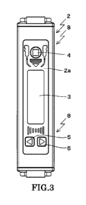
[Fig. 3]
Fig. 3 shows the embodiment of this invention and is a top view of the body 2
of the
buried-pipe damage location detection device 1 by this invention.
[Fig. 4]
Fig. 4 shows the embodiment of this invention and is a right side view of the
body 2
of the buried-pipe damage location detection device 1 by this invention.
[Fig. 5]
Fig. 5 shows the embodiment of this invention and is a left side view of the
body 2
of the buried-pipe damage location detection device 1 by this invention.
[Fig. 6]
Fig. 6 shows the embodiment of this invention and is a screen diagram showing
the
display screen 3 of the body 2 of the buried-pipe damaged location detection
device 1 by
this invention, where (a) is the starting screen 6 when turning on the power
switch 9,
and (b) is the usual screen 7 when turning on the power switch 9.
[Fig. 7]
Date Recue/Date Received 2022-09-29
CA 03178727 2022-09-29
Attorney Ref.: 4006P003CA01
Fig. 7 shows the embodiment of this invention, is a screen diagram showing the
display screen 3 of the body 2 of the buried-pipe damaged location detection
device 1 by
this invention, and is the usual screen 7 in case headphone 10 control the
volume.
[Fig. 81
Fig. 8 is a drawing in which showing the embodiment of this invention and
showing the display screen 3 of the body 2 of the buried-pipe damaged location
detection device 1 of the buried-pipe by this invention, where (a) is the
usual screen 7
which chooses the frequency band of a filter, (b) is the setting item
indication 7a at the
time of choosing a low pass filter setting (LPF) as a setting item, (c) is the
setting item
indication 7a at the time of choosing a high pass filter setting (HPF) as a
setting item,
(d) is the setting contents indication 7b which shows an example of the
contents of a
setting at the time of choosing a LPF setting as a setting item, and (e) is
the setting
contents indication 7b which shows an example of the contents of a setting at
the time
of choosing a HPF setting as a setting item.
[Fig. 91
Fig. 9 is a drawing in which showing the embodiment of this invention and
showing the display screen 3 of the body 2 of the buried-pipe damaged location
detection device 1 by this invention, where (a) is usually Screen 7 and (b) is
the setting
item indication 7a at the time of choosing a filter through setting (THRU) as
a setting
item, (c) and (d) is the setting contents indication 7b which shows an example
of the
contents of a setting at the time of choosing a filter through setting as a
setting item,
furthermore, (c) is the case of "ON" (when not passing a HPF/LPF circuit), (d)
is the
case of "OFF" (when following HPF/LPF setting), and both of them are the
setting
contents indication 7b.
[Fig. 101
Fig. 10 is a drawing in which showing the embodiment of this invention and
showing the display screen 3 of the body 2 of the buried-pipe damaged location
detection device 1 by this invention, where (a) is usually Screen 7, (b) is
the setting
item indication 7a at the time of choosing a back light setting (B.LIGHT) as a
setting
item, and (c) is the setting contents indication 7b which shows an example of
the
11
Date Recue/Date Received 2022-09-29
CA 03178727 2022-09-29
Attorney Ref.: 4006P003CA01
contents of a setting at the time of choosing a back light setting as a
setting item.
[Fig. 11[
Fig. 11 is a drawing in which showing the embodiment of this invention and
showing the display screen 3 of the body 2 of the buried-pipe damaged location
detection device 1 by this invention, (a) is usually Screen 7, (b) is the
setting item
indication 7a at the time of choosing a limiter setting (LIMIT) as a setting
item, and (c)
is the setting contents indication 7b which shows an example of the contents
of a
setting at the time of choosing a limiter setting as a setting item.
[Fig. 121
Fig. 12 is a drawing in which showing the embodiment of this invention and
showing the display screen 3 of the body 2 of the buried-pipe damaged location
detection device 1 of the buried-pipe 14 by this invention, (a) is usually
Screen 7, (b) is
the setting item indication 7a at the time of choosing a screen reversal
setting
(REVERSE) as a setting item, and (c) is the setting contents indication 7b
which shows
an example of the contents of a setting at the time of choosing a screen
reversal setting
as a setting item.
[Fig. 131
Fig. 13 is a drawing in which showing the embodiment of this invention and
showing the display screen 3 of the body 2 of the buried-pipe damaged location
detection device 1 of the buried-pipe 14 by this invention, (a) is usually
Screen 7 and (b)
is the setting item indication 7a at the time of choosing preset setting
memory
(PRESET) as a setting item at the time of starting, and (c) and (d) is the
setting
contents indication 7b which shows an example of the contents of a setting at
the time
of choosing setting memory (PRESET) as a setting item at the time of starting,
furthermore, (c) is the case of "NO" (when not keeping the various contents of
a setting
at the time of starting), and (d) is the setting contents indication 7b in
"YES" (when
keeping the various contents of a setting at the time of starting).
[Fig. 141 screen transition diagram
Fig. 14 is a drawing in which showing the embodiment of this invention and
showing the display screen 3 of the body 2 of the buried-pipe damaged location
12
Date Recue/Date Received 2022-09-29
CA 03178727 2022-09-29
Attorney Ref.: 4006P003CA01
detection device 1 of the buried-pipe 14 by this invention, and is a drawing
showing the
starting screen 6, the usual screen 7, setting item indication 7a at the time
of various
setting, the setting contents indication 7b, and the list of each setting
value.
[Fig. 151
Fig. 15 is a perspective view in which showing the prior art and showing the
composition of the leakage detection device 101.
[Fig. 161
Fig. 16 is an explanatory diagram in which showing the prior art and showing
the
case where the prior leakage detection device 101 detects the damaged part 91
of the
underground pipe 90.
DETAILED DESCRIPTION OF THE DRAWINGS
[00231
A connection mechanism between a water service meter in a meter box having a
transparent plate which covers a display surface, a water service meter head
ring
which binds this transparent plate and a water service meter cap, and a
leakage-of-water judging machine which places on the upper surface of this
water
service meter cap and inspects leakage-of-water, comprising:
a main part case which provided an opening in the bottom central part while
storing
electric parts inside, and is a component of the leakage-of-water judging
machine;
a support plate which opposite arranged in parallel via this main part case
bottom and
a gap, arranged to the perpendicular central line of the leakage-of-water
judging
machine at the equal angle, fixed to the bottom of the main part case via the
gap by the
three legs whose tip projects from lower part, and is a component of the
leakage-of-water judging machine;
a detection part which can detect leakage-of-water sound by contacting the
transparent
plate of the water service meter in the tip of the three legs which project
from this
support plate, and is a component of the leakage-of-water judging machine; and
a guide of a cave which is allocated in the gap between the bottom of the main
part case
and the support plate, hangs from the bottom of the main part case to the
support plate,
13
Date Recue/Date Received 2022-09-29
CA 03178727 2022-09-29
Attorney Ref.: 4006P003CA01
and is a component of the leakage-of-water judging machine;
wherein an acceleration sensor unit of the electric parts is stored in the
guide, is
arranged in parallel with the bottom of the main part case in contact with the
support
plate, is coincided a perpendicular central line with the central line of the
leakage-of-water judging machine, and is positioned and fixed to the opening
so as to be
located in the gap,
a power supply unit of the electric parts is coincided a perpendicular central
line with
the central line of the leakage-of-water judging machine, is stored by the
main part
case, is positioned in parallel over the acceleration sensor unit, and is
fixed to the main
part case,
a circuit board unit of the electric parts is coincided a perpendicular
central line with
the central line of the leakage-of-water judging machine, is positioned in
parallel with
the power supply unit, and is fixed to the main part case-so as to lower the
center of
gravity of the leakage-of-water judging machine,
at the time of leakage-of-water inspection, by placing this leakage-of-water
judging
machine in the upper surface of the water service meter cap, the tip of the
three legs of
the leakage-of-water judging machine, is connected to the water service meter
while it
is inscribed in the water service meter head ring, and the leakage-of-water
judging
machine is stood on the water service meter in a stable state.
the leg of the leakage-of-water judging machine is formed in a curve in the
direction of
a periphery to the central line,
the guide was integrally formed with a flange part positioned by the equal
angle to the
central line.
[Embodiment 1[
[00241
The 1st embodiment of this invention is explained in detail based on Figs. 1 -
Fig.
14.
Fig. 1 is the connection position of the buried-pipe damage location detection
device 1 of the buried-pipe by this invention a shown mimetic diagram, and the
buried-pipe damage location detection device 1 of a buried-pipe is constituted
by the
14
Date Recue/Date Received 2022-09-29
CA 03178727 2022-09-29
Attorney Ref.: 4006P003CA01
body 2, the pickup sensor 12 which makes the hand switch 11 placed between
these
body 2, and is connected to them by the connecting cable 12a, and the
headphone 10
connected with the body 2 through the connecting cable 10a.
In addition, 13 is earth surface, 14 is an buried-pipe, 15 is a damaged
location of the
buried-pipe 14, and 16 is a ripple of the leakage sound propagated on the
earth surface
13 from the damaged location 15.
[00251
[00261
The 1st embodiment of this invention is explained in detail based on Figs. 1 -
3.
Figs. 1 - 2 show the 1st embodiment of this invention, Fig. 1 is a cross
section of
leakage-of-water judging machine 1 of this invention, and Fig. 2 is an outline
drawing
of leakage-of-water judging machine 1 of this invention.
Fig. 2 (a) is an upper surface figure and panel surface 14a of display area 14
is shown,
(b) is an elevational view and (c) is a bottom plan view, (d) is a right side
view and (e)
is a principal part enlarged view of panel surface 14a.
[00271
As shown in Fig. 3, water service meter 34 is the usual water service meter
currently
generally used, and is allocated with stop cock 37 in meter box 35 currently
buried in
the ground.
Display surface 34b of display area 34a of water service meter 34 is covered
with water
service meter cap 34c.
This water service meter cap 34c is constituted by circular transparent plates
34d
which formed by transparent members like glass, and water service meter head
ring
34e which binds this transparent plate 34d.
The water service meter head ring 34e is projected from the surface of
transparent
plate 34d.
[00281
As shown in Figs. 1 - 2, leakage-of-water judging machine 1 is constituted by
rectangle-form main part case 2, circular support plate 3, three bolts 4 and
nut 4a
which constitute leg 9 of leakage-of-water judging machine 1 while fixing
support plate
Date Recue/Date Received 2022-09-29
CA 03178727 2022-09-29
Attorney Ref.: 4006P003CA01
3 to main part case 2 with a screw and cylindrical guide 5 for acceleration
sensor unit
11 being stored and protecting this acceleration sensor unit 11.
[00291
The upper end opening of main part case 2 for storing electric parts is
covered possible
opening and closing with cap 7, and opening 6 is in the bottom central part of
main part
case 2.
Support plate 3 is opposite arrangement in parallel with the bottom of main
part case 2,
and it is fixed to the bottom of main part case 2 with the screw via gap 8
with 3 sets of
bolts 4 and nut 4a.
The bolt 4 and nut 4a are radially positioned by the angles (120 degrees)
centering on
the perpendicular centerline A.
Therefore, three sets of bolt 4 and nut 4a constitute three legs 9 of leakage-
of-water
judging machine 1.
The tip of this leg 9 is projected in the lower part from support plate 3.
Therefore, wherein leakage-of-water judging machine 1 and water service meter
34 are
connected, the tip of leg 9 touches glass board 34d which cover display
surface 34b of
water service meter 34, and serves as detection part 10 for detecting
vibration by
leakage of water.
[00301
In this embodiment, although support plate 3 is circular, it may not be
limited to this
shape, may have the shape of a polygon, such as a quadrangle and a pentagon,
and
should just be the shape which horizontal balance was able to take to
perpendicular
central line A.
In this embodiment, although bolt 4 and nut (high nut) 4a constitute leg 9, it
is not
limited to this.
For example, the leg may be formed by the existing flexible member.
In this case, if three legs 9 are formed in a curve in the direction of a
periphery from a
central line, the connection to leakage-of-water judging machine 1 and water
service
meter 34 will be stabilized from the case where leg 9 is made to become
independent in
the shape of a straight line.
16
Date Recue/Date Received 2022-09-29
CA 03178727 2022-09-29
Attorney Ref.: 4006P003CA01
[00331
Guide 5 of the cave is allocated in gap 8 between main part case 2 and support
plate 3
so as to hang downward from the bottom of main part case 2 toward the support
plate
3.
One end of guide 5 is being positioned and fixed to the end of opening 6 in
the bottom of
main part case 2, and the other end of guide 5 is opened.
The outer wall of guide 5 is radially positioned by the equal angle focusing
on
perpendicular central line A, and flange part 5a extended in one from the
outer wall of
guide 5 is formed.
In this embodiment, although, main part case 2, guide 5, and its flange part
5a are
formed in one, it is not limited to this, may be formed by combining different
parts.
[00341
In this guide 5, acceleration sensor unit 11, which is relatively heavy parts
among
electric parts of leakage-of-water judging machine 1 is stored.
One end of this acceleration sensor unit 11 is projected in gap 8 from opening
6 of the
bottom of main part case 2 and it is fixed to the inner wall of guide 5 via
case 11a, and
the other end of acceleration sensor unit 11 is positioned and supported in
contact with
support plate 3.
The perpendicular central line of acceleration sensor unit 11 is positioned so
that it
may consist with perpendicular central line A.
[00351
That is, acceleration sensor unit 11 is stored in guide 5, and is arranged in
gap 8
located between the bottom of main part case 2 and support plate 3.
Therefore, the perpendicular height (length) of main part case 2 can be
shortened
sharply.
The center of gravity of leakage-of-water judging machine 1 can become low,
and the
connecting state of water service meter 34 and leakage-of-water judging
machine 1 can
be stabilized compared to conventional products.
[00361
17
Date Recue/Date Received 2022-09-29
CA 03178727 2022-09-29
Attorney Ref.: 4006P003CA01
When leakage-of-water judging machine 1 and water service meter 34 are
connected
for leakage-of-water inspection, both are settled in meter box 35.
Therefore, it is not influenced by a wind at the time of leakage-of-water
inspection.
Therefore, the stability of the connecting state of leakage-of-water judging
machine 1
and water service meter 34 increases further.
[00371
In the case of this embodiment, the shape of guide 5 is cylindrical, but it
may not be
limited to this, and the section of guide 5 are sufficient polygons, such as a
quadrangle
and a pentagon.
Guide 5 can store acceleration sensor unit 11 to the inside, and as long as it
is the shape
which maintains horizontal balance to perpendicular central line A, it may be
what
kind of shape.
Since the center of gravity of leakage-of-water judging machine 1 can be made
low
when a large weight member is used for the member of guide 5, the stability of
the
connecting state of leakage-of-water judging machine 1 and water service meter
34
increases.
[00381
Power supply unit 12 whose weight is the maximum in the electric parts of
leakage-of-water judging machine 1 is stored by main part case 2, and power
supply
unit 12 is located above acceleration sensor unit 11, coincides perpendicular
central
line A mutually, is positioned in piles in parallel, and is being fixed to
main part case 2.
Therefore, the center of gravity of leakage-of-water judging machine 1 is
further
lowered.
Circuit board unit 13 of electric parts coincides perpendicular central line A
of power
supply unit 12 with perpendicular central line A of acceleration sensor unit
11, and is
positioned in parallel, and is being stored and fixed to the cap 7 side of
main part case
2.
Therefore, since the circuit board conventionally allocated vertically was
allocated
horizontally, the height of a main part case can be shortened sharply, and the
center of
gravity of leakage-of-water judging machine 1 is also lowed.
18
Date Recue/Date Received 2022-09-29
CA 03178727 2022-09-29
Attorney Ref.: 4006P003CA01
[00391
As shown in Fig. 2 (a), cap 7 covers the upper end opening of main part case
2, and
indication area 14 is allocated on cap 7.
Therefore, a transparent bottom hole is formed at the part of cap 7 which
opposes panel
surface 14a and various kinds of holes for indicator lamps of indication area
14 and
indication lights, such as LED, are allocated in these transparent bottom
holes.
[00401
In the case of this embodiment, as shown in Fig. 2 (d), the result of leakage-
of-water
inspection expresses the doubt of leakage of water as three steps of waterdrop
marks
15.
By turning on operation switch 16, it is constituted so that indication 17 of
"end" or"
measuring" may be shown with color LED.
The liquid-crystal-display machine is used for display area 14 in this
embodiment.
[0041]
USB connector 18 is allocated in the right-hand side of main part case 2 with
the
waterproof connector cover.
By this USB connector 18, the result of leakage-of-water inspection can be
outputted to
external apparatus (PC etc.), the firmware of leakage-of-water judging machine
1 can
be updated, and power supply unit 12 can be changed.
[0042]
Next, function operation at the time of conducting leakage-of-water inspection
using
leakage-of-water judging machine 1 is explained based on Figs. 1 - 3.
[00431
First, inspection of a meter of water service meter 34 is carried out.
Cap object 35a of meter box 35 is opened, and, subsequently the numerical
value (the
amount of the water service used) displayed on display surface 34b of water
service
meter 34 is read.
By this act, the inspection of a meter of water service is ended.
[0044]
Subsequently, leakage-of-water inspection is carried out.
19
Date Recue/Date Received 2022-09-29
CA 03178727 2022-09-29
Attorney Ref.: 4006P003CA01
Leakage-of-water judging machine 1 is laid on glass board 34d of water service
meter
cap 34c which covers display surface 34b of water service meter 34.
Under the present circumstances, the tip of three legs 9 of leakage-of-water
judging
machine 1 touches water service meter head ring 34e, and leakage-of-water
judging
machine 1 and water service meter 34 are connected.
As described above, gap 8 is interposed between main part case 2 of leakage-of-
water
judging machine 1 and support plate 3, and acceleration sensor unit 11 with
relatively
heavy weight is allocated in this gap 8, and since power supply unit 12 with
the largest
weight within main part case 2 is allocated near the bottom of main part case
2, the
center of gravity of leakage-of-water judging machine 1 is very low compared
with
goods conventionally.
Moreover, the tip of leg 9 used as three detecting parts 10 is strongly in
contact with
water service meter head ring 34e projected from the surface of glass board
34d.
Therefore, since leakage-of-water judging machine 1 can stand being stabilized
by
three legs 9 on the surface of glass board 34d of meter cap 34c of water
service meter 34,
the connection mechanism between leakage-of-water judging machine 1 and water
service meter 34 is stabilized very much.
[00451
As described above, acceleration sensor unit 11 with relatively heavy weight
is
allocated in gap 8, circuit board unit 13 is also arranged in parallel with
main part case
2 and the perpendicular height of leakage-of-water judging machine 1 is also
designed
low.
Therefore, even if leakage-of-water judging machine 1 and water service meter
34 are
connected, since leakage-of-water judging machine 1 is settled in meter box
35, it is not
influenced by a wind and its stability improves further.
[00461
In this state, operation switch 16 is turned on and panel surface 14a of
display area 14
is read.
Under the present circumstances, when there is a leakage-of-water part,
leakage-of-water sound is detected with leakage-of-water judging machine 1,
and that
Date Recue/Date Received 2022-09-29
CA 03178727 2022-09-29
Attorney Ref.: 4006P003CA01
result is shown by either of three steps of waterdrop marks 15 which show the
doubt of
leakage of water to panel surface 14a.
This result can be outputted to external apparatus (PC etc.) via USB connector
18 or
built-in BLUETOOTH (registered trademark).
[0047]
Since this invention can also carry out leakage-of-water inspection
simultaneously at
the time of the inspection of a meter of a water service meter, it can use for
the water
service meter constructed all over the country.
[Description of Notations]
[0048]
1 Leakage-of-Water Judging Machine
2 Main Part Case of Leakage-of-Water Judging Machine 1
3 Support Plate
Guide
5a The flange part of guide 5
8 Gap
9 Leg
Perception Part
11 Acceleration Sensor Unit
12 Power Supply Unit
13 Circuit Board Unit
34 Water Service Meter
34b The display surface of water service meter 34
34c The meter cap of water service meter 34
34d Glass board of water service meter 34
34e The water service meter head ring of water service meter 34
A The perpendicular central line of leakage-of-water judging machine 1
21
Date Recue/Date Received 2022-09-29