Note: Descriptions are shown in the official language in which they were submitted.
WO 2021/233918
PCT/EP2021/063145
-1-
MODIFIED AEROSOL-GENERATING ARTICLE WITH FLAME RETARDANT WRAPPER
The present invention relates to an aerosol-generating article comprising an
aerosol-
generating substrate and adapted to produce an inhalable aerosol upon heating.
Aerosol-generating articles in which an aerosol-generating substrate, such as
a tobacco-
containing substrate, is heated rather than combusted, are known in the art.
In a conventional cigarette, a consumer applies a flame to the distal end of
the cigarette
whilst drawing air through the proximal end. The heat generated locally by the
flame and the
oxygen in the air drawn through the cigarette causes ignition of the distal
end of the cigarette, and
combustion of the tobacco rod and the surrounding wrapper generates an
inhalable smoke. By
contrast, in heated aerosol-generating articles, an aerosol is generated by a
more gentle transfer
of heat from a heat source to a physically separate aerosol-generating
substrate or material;
which may be located in contact with, within, around, or downstream of the
heat source. During
use of the aerosol-generating article, volatile compounds are released from
the aerosol-
generating substrate by heat transfer from the heat source and are entrained
in air drawn through
the aerosol-generating article. As the released compounds cool, they condense
to form an
aerosol.
A number of prior art documents disclose aerosol-generating devices for
consuming
aerosol-generating articles. Such devices include, for example, electrically
heated aerosol-
generating devices in which an aerosol is generated by the transfer of heat
from one or more
electrical heater elements of the aerosol-generating device to the aerosol-
generating substrate of
a heated aerosol-generating article. For example, electrically heated aerosol-
generating devices
have been proposed that comprise an internal heater blade which is adapted to
be inserted into
the aerosol-generating substrate. As an alternative, inductively heatable
aerosol-generating
articles comprising an aerosol-generating substrate and a susceptor arranged
within the aerosol-
generating substrate have also been proposed.
Aerosol-generating articles in which a tobacco-containing substrate is heated
rather than
combusted present a number of challenges that were not encountered with
conventional smoking
articles.
The tobacco-containing substrates are typically heated to
significantly lower
temperatures compared with the temperatures reached by the combustion front in
a conventional
cigarette. However, heating temperatures cannot be too low, as this may have
an impact on
nicotine release from the tobacco-containing substrate and nicotine delivery
to the consumer.
Further. in order to maximise heat transfer efficiency, it is generally
desirable that the heat source
be located as close as possible to, and preferably in contact with the aerosol-
generating substrate.
Therefore, in existing aerosol-generating articles designed to be heated by
means of a
heater blade inserted into the aerosol-generating substrate or by means of
susceptor arranged
within the aerosol-generating substrate, the aerosol-generating substrate is
typically
CA 03179285 2022- 11- 17
WO 2021/233918
PCT/EP2021/063145
-2-
circumscribed by a wrapper combining a paper layer with a metallic foil, such
as aluminium foil.
Thus, the metallic layer interposed between the aerosol-generating substrate
and the paper
wrapper acts as a thermal shield and prevents the paper wrapper from becoming
scorched or
charred during use.
This is desirable because it increases safety of use of the aerosol-generating
article and
prevents delivery of paper combustion products or paper pyrolysis products to
the consumer
during use. However, the inclusion of one such metallic shield makes the
manufacturing process
more complex and costly, and may lead to an increased environmental impact of
the aerosol-
generating article when this is disposed of after use. Further, as the
original visual impact of the
aerosol-generating article is substantively preserved during use, it may be
difficult to tell whether
an aerosol-generating article has effectively been used or not.
Accordingly; it would be desirable to provide a novel and improved aerosol-
generating
article that is easier to dispose of and has a reduced environmental impact,
whilst at the same
time being adapted to prevent scorching or charring of the article during use.
Secondly, a need
is generally felt for a novel and improved aerosol-generating article that
substantially prevents
misuse of the article, such that the article can only be correctly employed in
an aerosol-generating
device adapted to heat the aerosol-generating substrate and not used as a
conventional cigarette.
Further, it would be desirable to provide one such aerosol-generating article
that can be
manufactured efficiently and at high speed, preferably without the need for
extensive modification
of existing equipment.
Therefore, it would be desirable to provide a new and improved aerosol-
generating article
adapted to achieve at least one of the desirable results described above.
The present disclosure relates to an aerosol-generating article for producing
an inhalable
aerosol upon heating, the aerosol-generating article comprising a rod of
aerosol-generating
substrate extending from a rod proximal end to a rod distal end upstream from
the rod proximal
end. The aerosol-generating substrate may comprise at least an aerosol-former.
The aerosol-
generating article may comprise a downstream section at a location downstream
of the rod of
aerosol-generating substrate.
The aerosol-generating article may comprise a wrapper
circumscribing at least the rod of aerosol-generating substrate. The wrapper
may comprise a
wrapping base material having a basis weight. At least a treated portion of
the wrapper extending
between the rod proximal end and the rod distal end may comprise a flame
retardant composition
comprising one or more flame retardant compounds, such that the treated
portion of the wrapper
has an overall basis weight greater than the basis weight of the wrapping base
material. The
treated portion may extend over at least about 80 percent of an outer surface
area of the rod of
aerosol-generating substrate.
According to the present invention, there is provided an aerosol-generating
article for
producing an inhalable aerosol upon heating, the aerosol-generating article
comprising: a rod of
CA 03179285 2022- 11- 17
WO 2021/233918
PCT/EP2021/063145
-3-
aerosol-generating substrate extending from a rod proximal end to a rod distal
end upstream from
the rod proximal end; a downstream section at a location downstream of the rod
of aerosol-
generating substrate; and a wrapper circumscribing at least the rod of aerosol-
generating
substrate, the wrapper comprising a wrapping base material having a basis
weight. At least a
treated portion of the wrapper extending between the rod proximal end and the
rod distal end
comprises a flame retardant composition comprising one or more flame retardant
compounds,
such that the treated portion of the wrapper has an overall basis weight
greater than the basis
weight of the wrapping base material. The treated portion extends over at
least about 80 percent
of an outer surface area of the rod of aerosol-generating substrate.
The present disclosure further relates to a method of manufacturing an aerosol-
generating
article for generating an inhalable aerosol upon heating. The method may
comprise a step of
providing a continuous rod of aerosol-generating substrate. The method may
comprise a further
step of circumscribing the continuous rod of aerosol-generating substrate with
a wrapper, the
wrapper comprising a wrapping base material having a dry basis weight. In
addition, the method
may comprise a step of treating at least a portion of the wrapper with a flame
retardant
composition comprising one or more flame retardant compounds, such as to
provide a treated
portion of the wrapper having an overall dry basis weight greater than the dry
basis weight of the
wrapping base material. Further, the method may comprise a step of cutting the
treated wrapped
continuous rod of aerosol-generating substrate into discrete rods, each
discrete rod extending
from a discrete rod proximal end to a discrete rod distal end upstream from
the discrete rod
proximal end, such that a treated portion of the discrete rod extends over at
least about 80 percent
of an outer surface area of the discrete rod.
According to the present invention, there is further provided a method of
manufacturing
an aerosol-generating article for generating an inhalable aerosol upon
heating, the method
comprising: providing a continuous rod of aerosol-generating substrate;
circumscribing the
continuous rod of aerosol-generating substrate with a wrapper, the wrapper
comprising a
wrapping base material having a dry basis weight; treating at least a portion
of the wrapper with
a flame retardant composition comprising one or more flame retardant
compounds, such as to
provide a treated portion of the wrapper having an overall dry basis weight
greater than the dry
basis weight of the wrapping base material; cutting the treated wrapped
continuous rod of aerosol-
generating substrate into discrete rods, each discrete rod extending from a
discrete rod proximal
end to a discrete rod distal end upstream from the discrete rod proximal end,
such that a treated
portion of the discrete rod extends over at least about 80 percent of an outer
surface area of the
discrete rod.
The present disclosure also relates to an aerosol-generating system comprising
an
electrically operated aerosol-generating device and an aerosol-generating
article as set out
above. The aerosol-generating device may comprise means for heating the rod of
aerosol-
CA 03179285 2022- 11-17
WO 2021/233918
PCT/EP2021/063145
-4-
generating substrate to a temperature sufficient to generate an aerosol from
the aerosol-
generating substrate.
According to the present invention, there is additionally provided an aerosol-
generating
system comprising an electrically operated aerosol-generating device and an
aerosol-generating
article as described above, the aerosol-generating device comprising means for
heating the rod
of aerosol-generating substrate to a temperature sufficient to generate an
aerosol from the
aerosol-generating substrate.
As described briefly above, the present invention provides an aerosol-
generating article
for producing an inhalable aerosol upon heating, wherein the article comprises
a rod of aerosol-
generating substrate extending from a rod proximal end to a rod distal end
upstream from the rod
proximal end, and a downstream section at a location downstream of the rod of
aerosol-
generating substrate. In more detail, the present invention provides an
aerosol-generating article
for producing an inhalable aerosol upon heating at a temperature from about
100 degrees Celsius
to about 800 degrees Celsius, preferably from about 150 degrees Celsius to
about 500 degrees
Celsius, more preferably from about 200 degrees Celsius to about 300 degrees
Celsius.
These temperatures are significantly lower than the temperatures reached in a
conventional cigarette upon combustion of a tobacco-containing substrate, and
even more
significantly lower than the temperatures reached by commercially available
cigarette lighters,
which can be in the range from about 1000 degrees Celsius to 2000 degrees
Celsius and even
higher.
Further, the aerosol-generating article comprises a wrapper circumscribing at
least the
rod of aerosol-generating substrate, the wrapper comprising a wrapping base
material having a
basis weight. In contrast to existing aerosol-generating articles, at least a
treated portion of the
wrapper extending between the rod proximal end and the rod distal end
comprises a flame
retardant composition comprising one or more flame retardant compounds. Thus,
the treated
portion of the wrapper has an overall basis weight greater than the basis
weight of the wrapping
base material. The treated portion extends over at least about 80 percent of
an outer surface
area of the rod of aerosol-generating substrate.
The inventors have found that by circumscribing the aerosol-generating
substrate with a
wrapper wherein a treated portion of the wrapper comprises a flame retardant
composition, the
treated portion extending over the great majority of the outer surface area of
the rod of aerosol-
generating substrate, it is advantageously possible to prevent the wrapper and
the underlying
aerosol-generating substrate from charring or scorching upon heating during
use. In other words,
it is advantageously possible to substantially prevent combustion and
pyrolysis of components of
aerosol-generating articles in accordance with the present invention.
In aerosol-generating articles in accordance with the present invention, this
is desirably
achieved without the need for an additional layer of metallic foil or other
heat-shielding material
CA 03179285 2022- 11- 17
WO 2021/233918
PCT/EP2021/063145
-5-
to be included in the aerosol-generating article. This simplifies the
manufacturing process and
may therefore reduce manufacturing costs. It also becomes easier to dispose of
an aerosol-
generating article in accordance with the present invention, as there is no
need to separate and
recover a valuable recyclable material, such as for example aluminium foil,
when a used aerosol-
generating article is discarded. In addition, the inventors have found that by
circumscribing the
aerosol-generating substrate by means of a wrapper as described above, when
the aerosol-
generating substrate has been exposed, during use, to temperatures in the
range from about 100
degrees Celsius to about 800 degrees Celsius, the aerosol-generating article
appears
significantly discoloured, the surface of the wrapper having turned dark brown
or blackish. As
such, it is immediately possible for the consumer to tell whether an aerosol-
generating article has
been used before and should be discarded.
By adjusting the amount of flame retardant compound in the wrapper (for
example, in
terms of amount per square metre of surface area of the treated portion), the
extent to which the
surface of wrapper is treated with the flame retardant composition within the
range described
above, as well as the formulation of the flame retardant composition (that is,
the nature of the
flame retardant compound or compounds), it is advantageously possible to
enhance the flame
retardant properties of the wrapper and of the aerosol-generating article as a
whole.
Thus. the present invention provides an improved aerosol-generating article
that is
capable of substantially preventing scorching and charring of the aerosol-
generating substrate
and wrapper during use. This is because by providing one or more flame
retardant compounds
on the wrapper or within the wrapper or both it is possible to substantially
prevent that heat
supplied to the article for generating an aerosol cause pyrolysis or
combustion of the wrapper
base material.
Aerosol-generating articles in accordance with the present invention are
advantageously
easy to dispose of and have a reduced environmental impact, as there is no
need for the articles
to include a metallic foil layer as is commonly the case in existing aerosol-
generating articles.
Further, an aerosol-generating article in accordance with the present
invention has the
additional benefit that it can only be correctly employed as intended, that
is, in combination with
a device adapted to heat the aerosol-generating substrate. In fact, unlike a
conventional cigarette,
an aerosol-generating article according to the invention essentially cannot be
ignited and is unable
to sustain combustion like a conventional cigarette.
In accordance with the present invention there is provided an aerosol-
generating article for
generating an inhalable aerosol upon heating.
The term "aerosol generating article" is used herein to denote an article
wherein an aerosol
generating substrate is heated to produce an deliver inhalable aerosol to a
consumer. As used
herein, the term "aerosol generating substrate" denotes a substrate capable of
releasing volatile
compounds upon heating to generate an aerosol.
CA 03179285 2022- 11-17
WO 2021/233918
PCT/EP2021/063145
-6-
A conventional cigarette is lit when a user applies a flame to one end of the
cigarette and
draws air through the other end. The localised heat provided by the flame and
the oxygen in the
air drawn through the cigarette causes the end of the cigarette to ignite, and
the resulting
combustion generates an inhalable smoke. By contrast, in heated aerosol
generating articles, an
aerosol is generated by heating a flavour generating substrate, such as
tobacco. Known heated
aerosol generating articles include, for example, electrically heated aerosol
generating articles
and aerosol generating articles in which an aerosol is generated by the
transfer of heat from a
combustible fuel element or heat source to a physically separate aerosol
forming material. For
example, aerosol generating articles according to the invention find
particular application in
aerosol generating systems comprising an electrically heated aerosol
generating device having
an internal heater blade which is adapted to be inserted into the rod of
aerosol generating
substrate. Aerosol generating articles of this type are described in the prior
art, for example, in
EP 0822670.
As used herein, the term "aerosol generating device" refers to a device
comprising a heater
element that interacts with the aerosol generating substrate of the aerosol
generating article to
generate an aerosol.
As used herein with reference to the present invention, the term "rod" is used
to denote a
generally cylindrical element of substantially circular, oval or elliptical
cross-section.
As used herein, the term "longitudinal" refers to the direction corresponding
to the main
longitudinal axis of the aerosol-generating article, which extends between the
upstream and
downstream ends of the aerosol-generating article. As used herein, the terms
"upstream" and
"downstream" describe the relative positions of elements, or portions of
elements, of the aerosol-
generating article in relation to the direction in which the aerosol is
transported through the
aerosol-generating article during use.
During use, air is drawn through the aerosol-generating article in the
longitudinal direction.
The term "transverse" refers to the direction that is perpendicular to the
longitudinal axis. Any
reference to the "cross-section" of the aerosol-generating article or a
component of the aerosol-
generating article refers to the transverse cross-section unless stated
otherwise.
The term "length" denotes the dimension of a component of the aerosol-
generating article
in the longitudinal direction. For example, it may be used to denote the
dimension of the rod or
of the elongate tubular elements in the longitudinal direction.
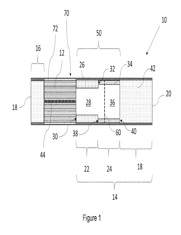
An aerosol-generating article in accordance with the present invention
comprises a rod of
aerosol-generating substrate. The rod of aerosol-generating substrate extends
from a rod
proximal end to a rod distal end upstream from the rod proximal end. Further,
the aerosol-
generating article comprises a downstream section at a location downstream of
the rod of aerosol-
generating substrate.
CA 03179285 2022- 11-17
WO 2021/233918
PCT/EP2021/063145
-7-
In aerosol-generating articles in accordance with the present invention, at
least the rod of
aerosol-generating substrate is circumscribed by a wrapper. This means that in
aerosol-
generating articles in accordance with the present invention the same wrapper
circumscribing the
rod of aerosol-generating substrate may also circumscribe at least a portion
of the downstream
section or at least a portion of an optional additional component of the
aerosol-generating article
provided at a location upstream of the rod of aerosol-generating substrate or
both.
The aerosol-generating article may have an overall length from about 35
millimetres to
about 100 millimetres.
Preferably, an overall length of an aerosol-generating article in accordance
with the
invention is at least about 38 millimetres. More preferably, an overall length
of an aerosol-
generating article in accordance with the invention is at least about 40
millimetres. Even more
preferably, an overall length of an aerosol-generating article in accordance
with the invention is
at least about 42 millimetres.
In some embodiments, an overall length of an aerosol-generating article in
accordance
with the invention is preferably less than or equal to 80 millimetres. More
preferably, an overall
length of an aerosol-generating article in accordance with the invention is
less than or equal to 70
millimetres. Even more preferably, an overall length of an aerosol-
generating article in
accordance with the invention is preferably less than or equal to 60
millimetres. Most preferably,
an overall length of an aerosol-generating article in accordance with the
invention is preferably
less than or equal to 50 millimetres.
In preferred embodiments, an overall length of the aerosol-generating article
is from about
38 millimetres to about 70 millimetres, more preferably from about 40
millimetres to about 70
millimetres, even more preferably from about 42 millimetres to about 70
millimetres. In other
embodiments, an overall length of the aerosol-generating article is preferably
from about 38
millimetres to about 60 millimetres, more preferably from about 40 millimetres
to about 60
millimetres, even more preferably from about 42 millimetres to about 60
millimetres. In further
embodiments, an overall length of the aerosol-generating article is preferably
from about 38
millimetres to about 50 millimetres, more preferably from about 40 millimetres
to about 50
millimetres, even more preferably from about 42 millimetres to about 50
millimetres. In an
exemplary embodiment, an overall length of the aerosol-generating article is
about 45 millimetres.
In other embodiments, an overall length of an aerosol-generating article in
accordance
with the invention is preferably at least about 40 millimetres, more
preferably about 50 millimetres,
even more preferably about 60 millimetres. In these embodiments, an overall
length of the
aerosol-generating is preferably less than or equal to about 95 millimetres,
more preferably less
than or equal to about 90 millimetres, even more preferably less than or equal
to about 85
millimetres, most preferably less than or equal to about 80 millimetres.
CA 03179285 2022- 11-17
WO 2021/233918
PCT/EP2021/063145
-8-
In preferred embodiments, an overall length of an aerosol-generating article
is from about
40 millimetres to about 95 millimetres, preferably from about 40 millimetres
to about 90
millimetres, more preferably from about 40 millimetres to about 85
millimetres, even more
preferably from about 40 millimetres to about 80 millimetres. In other
embodiments, an overall
length of an aerosol-generating article is from about 50 millimetres to about
95 millimetres,
preferably from about 50 millimetres to about 90 millimetres, more preferably
from about 50
millimetres to about 85 millimetres, even more preferably from about 50
millimetres to about 80
millimetres. In further embodiments, an overall length of an aerosol-
generating article is from
about 60 millimetres to about 95 millimetres, preferably from about 60
millimetres to about 90
millimetres, more preferably from about 60 millimetres to about 85
millimetres, even more
preferably from about 60 millimetres to about 80 millimetres. In yet further
embodiments, an
overall length of an aerosol-generating article is from about 70 millimetres
to about 95 millimetres,
preferably from about 70 millimetres to about 90 millimetres, more preferably
from about 70
millimetres to about 85 millimetres, even more preferably from about 70
millimetres to about 80
millimetres. In an exemplary embodiment, an overall length of the aerosol-
generating article is
about 75 millimetres.
An aerosol-generating article in accordance with the present invention may
have an
external diameter of at least 4 millimetres. Preferably, the aerosol-
generating article has an
external diameter of at least 5 millimetres. More preferably, the aerosol-
generating article has an
external diameter of at least 6 millimetres. Even more preferably, the aerosol-
generating article
has an external diameter of at least 7 millimetres.
Preferably, the aerosol-generating article has an external diameter of less
than or equal
to about 12 millimetres, More preferably, the aerosol-generating article has
an external diameter
of less than or equal to about 10 millimetres. Even more preferably, the
aerosol-generating article
has an external diameter of less than or equal to about 8 millimetres.
In some embodiments, the aerosol-generating article has an external diameter
from about
4 millimetres to about 12 millimetres, preferably from about 5 millimetres to
about 12 millimetres,
more preferably from about 6 millimetres to about 12 millimetres, even more
preferably from about
7 millimetres to about 12 millimetres. In other embodiments, the aerosol-
generating article has
an external diameter from about 4 millimetres to about 10 millimetres,
preferably from about 5
millimetres to about 10 millimetres, more preferably from about 6 millimetres
to about 10
millimetres, even more preferably from about 7 millimetres to about 10
millimetres. In further
embodiments, the aerosol-generating article has an external diameter from
about 4 millimetres to
about 8 millimetres, preferably from about 5 millimetres to about 8
millimetres, more preferably
from about 6 millimetres to about 8 millimetres. even more preferably from
about 7 millimetres to
about 8 millimetres.
The rod of aerosol-generating substrate may have a length of between about 5
millimetres
CA 03179285 2022- 11-17
WO 2021/233918
PCT/EP2021/063145
-9-
and about 100 mm.
In some embodiments, the rod of aerosol-generating substrate preferably has a
length of
at least about 6 millimetres, more preferably at least about 7 millimetres. In
these embodiments.
the rod of aerosol-generating substrate may have a length of less than about
90 millimetres and
preferably has a length of less than about 70 millimetres, more preferably
less than about 65
millimetres, more preferably less than about 50 millimetres, most preferably
less than 40
millimetres. In particularly preferred embodiments, the rod of aerosol-
generating substrate has a
length of less than about 35 millimetres, more preferably less than 25
millimetres, even more
preferably less than about 20 millimetres. In one embodiment, the rod of
aerosol-generating
substrate may have a length of about 10 millimetres. In a preferred
embodiment, the rod of
aerosol-generating substrate has a length of about 12 millimetres. This may be
combined with
an overall length of the aerosol-generating article of about 45 millimetres.
In other embodiments, the rod of aerosol-generating preferably has a length of
at least
about 10 millimetres, more preferably at least about 20 millimetres, even more
preferably at least
about 30 millimetres. In these embodiments, a length of the rod of aerosol-
generating substrate
is preferably less than or equal to about 60 millimetres, more preferably less
than or equal to
about 50 millimetres, even more preferably less than or equal to about 40
millimetres.
In preferred embodiments, a length of the rod of aerosol-generating substrate
is from
about 10 millimetres to about 60 millimetres, preferably from about 20
millimetres to about 60
millimetres, more preferably from about 30 millimetres to about 60
millimetres. In other
embodiments, a length of the rod of aerosol-generating substrate is from about
10 millimetres to
about 50 millimetres, preferably from about 20 millimetres to about 50
millimetres, more preferably
from about 30 millimetres to about 50 millimetres. In further embodiments, a
length of the rod of
aerosol-generating substrate is from about 10 millimetres to about 40
millimetres, preferably from
about 20 millimetres to about 40 millimetres, more preferably from about 40
millimetres to about
60 millimetres. In an exemplary embodiment, a length of the rod of aerosol-
generating substrate
is about 35 millimetres. This may be combined with an overall length of the
aerosol-generating
article of about 75 millimetres.
Preferably, the rod of aerosol generating substrate has a substantially
uniform cross-
section along the length of the rod. Particularly preferably, the rod of
aerosol generating substrate
has a substantially circular cross-section.
In aerosol-generating articles in accordance with the present invention, a
density of the
aerosol-generating substrate is preferably greater than about 300 milligrams
per cubic centimetre.
As used herein, with reference to the aerosol-generating substrate of aerosol-
generating articles
in accordance with the present invention, the term "density" refers to the
"apparent density" or
"volumetric density" of the substrate, and equals the total mass of the body
of aerosol-generating
substrate of given volume, which is the mass of the homogenised plant
material, aerosol former,
CA 03179285 2022- 11- 17
WO 2021/233918
PCT/EP2021/063145
-10-
etc. or the mass of the gel composition of given volume, divided by said given
volume of the rod
of aerosol-generating substrate.
As such, for example, the density of the aerosol-generating substrate
determines the mass
of a body of homogenised tobacco material of given volume and the packing
efficiency of a given
surface area of homogenised tobacco material. The density of a homogenised
tobacco material
is normally largely determined by the type of process used for the manufacture
thereof. A number
of reconstitution processes for producing homogenised tobacco materials are
known in the art.
These include, but are not limited to: paper-making processes of the type
described in, for
example, US-A-5,724,998; casting processes of the type described in, for
example, US-A-
5,724,998; dough reconstitution processes of the type described in, for
example, US-A-3,894,544;
and extrusion processes of the type described in, for example. in GB-A-
983,928.
Typically, the densities of homogenised tobacco materials produced by
extrusion
processes and dough reconstitution processes are greater than the densities of
homogenised
tobacco materials produced by casting processes. The densities of homogenised
tobacco
materials produced by extrusion processes can be greater than the densities of
homogenised
tobacco materials produced by dough reconstitution processes.
By way of example, a density of the aerosol-generating substrate is at least
about 310
milligrams per cubic centimetre or at least about 320 milligrams per cubic
centimetre or at least
about 330 milligrams per cubic centimetre.
In some embodiments, a density of the aerosol-generating substrate is
preferably at least
about 350 milligrams per cubic centimetre. More preferably, a density of the
aerosol-generating
substrate is at least about 400 milligrams per cubic centimetre. Even more
preferably, a density
of the aerosol-generating substrate is at least about 450 milligrams per cubic
centimetre. In
particularly preferred embodiments, a density of the aerosol-generating
substrate is at least about
500 milligrams per cubic centimetre. Preferably, a density of the aerosol-
generating substrate is
less than or equal to about 1000 milligrams per cubic centimetre, more
preferably less than or
equal to about 900 milligrams per cubic centimetre, even more preferably less
than or equal to
about 800 milligrams per cubic centimetre. By way of example, a density of the
aerosol-
generating substrate may be from about 350 milligrams per cubic centimetre to
about 1000
milligrams per cubic centimetre, preferably from about 400 milligrams per
cubic centimetre to
about 1000 milligrams per cubic centimetre, more preferably from about 450
milligrams per cubic
centimetre to about 1000 milligrams per cubic centimetre, even more preferably
from about 500
milligrams per cubic centimetre to about 1000 milligrams per cubic centimetre.
As another
example, a density of the aerosol-generating substrate may be from about 350
milligrams per
cubic centimetre to about 900 milligrams per cubic centimetre, preferably from
about 400
milligrams per cubic centimetre to about 900 milligrams per cubic centimetre,
more preferably
from about 450 milligrams per cubic centimetre to about 900 milligrams per
cubic centimetre,
CA 03179285 2022- 11-17
WO 2021/233918
PCT/EP2021/063145
-11-
even more preferably from about 500 milligrams per cubic centimetre to about
900 milligrams per
cubic centimetre. As a further example, a density of the aerosol-generating
substrate may be
from about 350 milligrams per cubic centimetre to about 800 milligrams per
cubic centimetre,
preferably from about 400 milligrams per cubic centimetre to about 800
milligrams per cubic
centimetre, more preferably from about 450 milligrams per cubic centimetre to
about BOO
milligrams per cubic centimetre, even more preferably from about 500
milligrams per cubic
centimetre to about 800 milligrams per cubic centimetre.
In other embodiments, a density of the aerosol-generating substrate is at
least about 600
milligrams per cubic centimetre, preferably at least about 700 milligrams per
cubic centimetre,
more preferably at least about 800 milligrams per cubic centimetre, even more
preferably at least
about 900 milligrams per cubic centimetre. In some particularly preferred
embodiments, a density
of the aerosol-generating substrate is at least about 1 gram per cubic
centimetre, preferably at
least about 1.1 grams per cubic centimetre, more preferably at least about 1.2
grams per cubic
centimetre, even more preferably at least about 1.3 grams per cubic
centimetre. Preferably, a
density of the aerosol-generating substrate is less than or equal to about 2.0
grams per cubic
centimetre, more preferably less than or equal to about 1.9 grams per cubic
centimetre, even
more preferably less than or equal to 1.8 grams per cubic centimetre. In
preferred embodiments,
a density of the aerosol-generating substrate is less than or equal to about
1.7 grams per cubic
centimetre, more preferably less than or equal to about 1.6 grams per cubic
centimetre, even
more preferably less than or equal to about 1.5 grams per cubic centimetre.
As an example, a density of the aerosol-generating substrate is from about 1
gram per
cubic centimetre to about 1.7 grams per cubic centimetre, preferably from
about 1.1 grams per
cubic centimetre to about 1.7 grams per cubic centimetre, more preferably from
about 1.2 grams
per cubic centimetre to about 1.7 grams per cubic centimetre, even more
preferably from about
1.3 grams per cubic centimetre to about 1.7 grams per cubic centimetre. As
another example, a
density of the aerosol-generating substrate is from about 1 gram per cubic
centimetre to about
1.6 grams per cubic centimetre, preferably from about 1.1 grams per cubic
centimetre to about
1.6 grams per cubic centimetre, more preferably from about 1.2 grams per cubic
centimetre to
about 1.6 grams per cubic centimetre, even more preferably from about 1.3
grams per cubic
centimetre to about 1.6 grams per cubic centimetre. As a further example, a
density of the
aerosol-generating substrate is from about 1 gram per cubic centimetre to
about 1.5 grams per
cubic centimetre, preferably from about 1.1 grams per cubic centimetre to
about 1.5 grams per
cubic centimetre, more preferably from about 1.2 grams per cubic centimetre to
about 1.5 grams
per cubic centimetre, even more preferably from about 1.3 grams per cubic
centimetre to about
1.5 grams per cubic centimetre.
The aerosol-generating substrate may be a solid aerosol-generating substrate.
CA 03179285 2022- 11-17
WO 2021/233918
PCT/EP2021/063145
-12-
In certain preferred embodiments, the aerosol-generating substrate comprises
homogenised plant material, preferably a homogenised tobacco material.
As used herein, the term "homogenised plant material" encompasses any plant
material
formed by the agglomeration of particles of plant. For example, sheets or webs
of homogenised
tobacco material for the aerosol-generating substrates of the present
invention may be formed by
agglomerating particles of tobacco material obtained by pulverising, grinding
or comminuting plant
material and optionally one or more of tobacco leaf lamina and tobacco leaf
stems. The
homogenised plant material may be produced by casting, extrusion, paper making
processes or
other any other suitable processes known in the art.
The homogenised plant material can be provided in any suitable form. For
example, the
homogenised plant material may be in the form of one or more sheets. As used
herein with
reference to the invention, the term "sheet" describes a laminar element
having a width and length
substantially greater than the thickness thereof.
Alternatively or in addition, the homogenised plant material may be in the
form of a plurality
of pellets or granules.
Alternatively or in addition, the homogenised plant material may be in the
form of a plurality
of strands, strips or shreds. As used herein, the term "strand" describes an
elongate element of
material having a length that is substantially greater than the width and
thickness thereof. The
term "strand" should be considered to encompass strips, shreds and any other
homogenised plant
material having a similar form. The strands of homogenised plant material may
be formed from
a sheet of homogenised plant material, for example by cutting or shredding, or
by other methods,
for example, by an extrusion method.
In some embodiments, the strands may be formed in situ within the aerosol-
generating
substrate as a result of the splitting or cracking of a sheet of homogenised
plant material during
formation of the aerosol-generating substrate, for example, as a result of
crimping. The strands
of homogenised plant material within the aerosol-generating substrate may be
separate from
each other. Alternatively, each strand of homogenised plant material within
the aerosol-
generating substrate may be at least partially connected to an adjacent strand
or strands along
the length of the strands. For example. adjacent strands may be connected by
one or more fibres.
This may occur, for example, where the strands have been formed due to the
splitting of a sheet
of homogenised plant material during production of the aerosol-generating
substrate, as
described above.
Preferably, the aerosol-generating substrate is in the form of one or more
sheets of
homogenised plant material. In various embodiments of the invention, the one
or more sheets of
homogenised plant material may be produced by a casting process. In various
embodiments of
the invention, the one or more sheets of homogenised plant material may be
produced by a paper-
making process. The one or more sheets as described herein may each
individually have a
CA 03179285 2022- 11- 17
WO 2021/233918
PCT/EP2021/063145
-13-
thickness of between 100 micrometres and 600 micrometres, preferably between
150
micrometres and 300 micrometres, and most preferably between 200 micrometres
and 250
micrometres. Individual thickness refers to the thickness of the individual
sheet, whereas
combined thickness refers to the total thickness of all sheets that make up
the aerosol-generating
substrate. For example, if the aerosol-generating substrate is formed from two
individual sheets,
then the combined thickness is the sum of the thickness of the two individual
sheets or the
measured thickness of the two sheets where the two sheets are stacked in the
aerosol-generating
substrate.
The one or more sheets as described herein may each individually have a
grammage of
between about 100 g/m2 and about 300 g/m2.
The one or more sheets as described herein may each individually have a
density of
from about 0.3 g/cm3to about 1.3 g/cm3, and preferably from about 0.7 g/cm3 to
about 1.0
g/cm3.
In embodiments of the present invention in which the aerosol-generating
substrate
comprises one or more sheets of homogenised plant material, the sheets are
preferably in the
form of one or more gathered sheets. As used herein, the term "gathered"
denotes that the sheet
of homogenised plant material is convoluted, folded, or otherwise compressed
or constricted
substantially transversely to the cylindrical axis of a plug or a rod.
The one or more sheets of homogenised plant material may be gathered
transversely
relative to the longitudinal axis thereof and circumscribed with a wrapper to
form a continuous
rod or a plug.
The one or more sheets of homogenised plant material may advantageously be
crimped
or similarly treated. As used herein, the term "crimped" denotes a sheet
having a plurality of
substantially parallel ridges or corrugations. Alternatively or in addition to
being crimped, the one
or more sheets of homogenised plant material may be embossed, debossed,
perforated or
otherwise deformed to provide texture on one or both sides of the sheet.
Preferably, each sheet of homogenised plant material may be crimped such that
it has a
plurality of ridges or corrugations substantially parallel to the cylindrical
axis of the plug. This
treatment advantageously facilitates gathering of the crimped sheet of
homogenised plant
material to form the plug. Preferably, the one or more sheets of homogenised
plant material may
be gathered. It will be appreciated that crimped sheets of homogenised plant
material may
alternatively or in addition have a plurality of substantially parallel ridges
or corrugations disposed
at an acute or obtuse angle to the cylindrical axis of the plug. The sheet may
be crimped to such
an extent that the integrity of the sheet becomes disrupted at the plurality
of parallel ridges or
corrugations causing separation of the material, and results in the formation
of shreds, strands or
strips of homogenised plant material.
CA 03179285 2022- 11- 17
WO 2021/233918
PCT/EP2021/063145
-14-
Alternatively, the one or more sheets of homogenised plant material may be cut
into
strands as referred to above. In such embodiments, the aerosol-generating
substrate comprises
a plurality of strands of the homogenised plant material. The strands may be
used to form a plug.
Typically, the width of such strands is about 5 millimetres, or about 4
millimetres, or about 3
millimetres, or about 2 millimetres or less. The length of the strands may be
greater than about
5 millimetres, between about 5 millimetres to about 15 millimetres, about 8
millimetres to about
12 millimetres, or about 12 millimetres. Preferably, the strands have
substantially the same length
as each other. The length of the strands may be determined by the
manufacturing process
whereby a rod is cut into shorter plugs and the length of the strands
corresponds to the length of
the plug. The strands may be fragile which may result in breakage especially
during transit. In
such cases, the length of some of the strands may be less than the length of
the plug.
The plurality of strands preferably extend substantially longitudinally along
the length of
the aerosol-generating substrate, aligned with the longitudinal axis.
Preferably, the plurality of
strands are therefore aligned substantially parallel to each other.
The homogenised plant material may comprise up to about 95 percent by weight
of plant
particles, on a dry weight basis. Preferably, the homogenised plant material
comprises up to
about 90 percent by weight of plant particles, more preferably up to about 80
percent by weight
of plant particles, more preferably up to about 70 percent by weight of plant
particles, more
preferably up to about 60 percent by weight of plant particles, more
preferably up to about 50
percent by weight of plant particles, on a dry weight basis.
For example, the homogenised plant material may comprise between about 2.5
percent
and about 95 percent by weight of plant particles, or about 5 percent and
about 90 percent by
weight of plant particles, or between about 10 percent and about 80 percent by
weight of plant
particles, or between about 15 percent and about 70 percent by weight of plant
particles, or
between about 20 percent and about 60 percent by weight of plant particles, or
between about
percent and about 50 percent by weight of plant particles, on a dry weight
basis.
In certain embodiments of the invention, the homogenised plant material is a
homogenised tobacco material comprising tobacco particles. Sheets of
homogenised tobacco
material for use in such embodiments of the invention may have a tobacco
content of at least
30 about 40 percent by weight on a dry weight basis, more preferably of at
least about 50 percent by
weight on a dry weight basis more preferably at least about 70 percent by
weight on a dry weight
basis and most preferably at least about 90 percent by weight on a dry weight
basis.
With reference to the present invention, the term "tobacco particles"
describes particles of
any plant member of the genus Nicotiana. The term "tobacco particles"
encompasses ground or
powdered tobacco leaf lamina, ground or powdered tobacco leaf stems, tobacco
dust, tobacco
fines, and other particulate tobacco by-products formed during the treating,
handling and shipping
of tobacco. In a preferred embodiment, the tobacco particles are substantially
all derived from
CA 03179285 2022- 11-17
WO 2021/233918
PCT/EP2021/063145
-15-
tobacco leaf lamina. By contrast, isolated nicotine and nicotine salts are
compounds derived from
tobacco but are not considered tobacco particles for purposes of the invention
and are not
included in the percentage of particulate plant material.
The tobacco particles may be prepared from one or more varieties of tobacco
plants. Any
type of tobacco may be used in a blend. Examples of tobacco types that may be
used include,
but are not limited to, sun-cured tobacco, flue-cured tobacco, Burley tobacco,
Maryland tobacco,
Oriental tobacco, Virginia tobacco, and other speciality tobaccos.
Flue-curing is a method of curing tobacco, which is particularly used with
Virginia
tobaccos. During the flue-curing process, heated air is circulated through
densely packed
tobacco. During a first stage, the tobacco leaves turn yellow and wilt. During
a second stage, the
laminae of the leaves are completely dried. During a third stage, the leaf
stems are completely
dried.
Burley tobacco plays a significant role in many tobacco blends. Burley tobacco
has a
distinctive flavour and aroma and also has an ability to absorb large amounts
of casing.
Oriental is a type of tobacco which has small leaves, and high aromatic
qualities. However,
Oriental tobacco has a milder flavour than, for example, Burley. Generally,
therefore, Oriental
tobacco is used in relatively small proportions in tobacco blends.
Kasturi, Madura and Jatim are subtypes of sun-cured tobacco that can be used.
Preferably, Kasturi tobacco and flue-cured tobacco may be used in a blend to
produce the tobacco
particles. Accordingly, the tobacco particles in the particulate plant
material may comprise a blend
of Kasturi tobacco and flue-cured tobacco.
The tobacco particles may have a nicotine content of at least about 2.5
percent by weight,
based on dry weight. More preferably, the tobacco particles may have a
nicotine content of at
least about 3 percent, even more preferably at least about 3.2 percent, even
more preferably at
least about 3.5 percent, most preferably at least about 4 percent by weight,
based on dry weight.
In certain other embodiments of the invention, the homogenised plant material
comprises
tobacco particles in combination with non-tobacco plant flavour particles.
Preferably, the non-
tobacco plant flavour particles are selected from one or more of: ginger
particles, eucalyptus
particles, clove particles and star anise particles. Preferably, in such
embodiments, the
homogenised plant material comprises at least about 2.5 percent by weight of
the non-tobacco
plant flavour particles, on a dry weight basis, with the remainder of the
plant particles being
tobacco particles. Preferably, the homogenised plant material comprises at
least about 4 percent
by weight of non-tobacco plant flavour particles, more preferably at least
about 6 percent by
weight of non-tobacco plant flavour particles, more preferably at least about
8 percent by weight
of non-tobacco plant flavour particles and more preferably at least about 10
percent by weight of
non-tobacco plant flavour particles, on a dry weight basis. Preferably, the
homogenised plant
material comprises up to about 20 percent by weight of non-tobacco plant
flavour particles, more
CA 03179285 2022- 11- 17
WO 2021/233918
PCT/EP2021/063145
-16-
preferably up to about 18 percent by weight of non-tobacco plant flavour
particles, more preferably
up to about 16 percent by weight of non-tobacco plant flavour particles.
The weight ratio of the non-tobacco plant flavour particles and the tobacco
particles in the
particulate plant material forming the homogenised plant material may vary
depending on the
desired flavour characteristics and composition of the aerosol produced from
the aerosol-
generating substrate during use. Preferably, the homogenised plant material
comprises at least
a 1:30 weight ratio of non-tobacco plant flavour particles to tobacco
particles, more preferably at
least a 1:20 weight ratio of non-tobacco plant flavour particles to tobacco
particles, more
preferably at least a 1:10 weight ratio of non-tobacco plant flavour particles
to tobacco particles
and most preferably at least a1:5 weight ratio of non-tobacco plant flavour
particles to tobacco
particles, on a dry weight basis.
Alternatively or in addition to the inclusion of tobacco particles into the
homogenised plant
material of the aerosol-generating substrate according to the invention, the
homogenised plant
material may comprise cannabis particles. The term "cannabis particles" refers
to particles of a
cannabis plant, such as the species Cannabis sativa, Cannabis indica, and
Cannabis ruderalis.
The homogenised plant material preferably comprises no more than 95 percent by
weight
of the particulate plant material, on a dry weight basis. The particulate
plant material is therefore
typically combined with one or more other components to form the homogenised
plant material.
The homogenised plant material may further comprise a binder to alter the
mechanical
properties of the particulate plant material, wherein the binder is included
in the homogenised
plant material during manufacturing as described herein. Suitable exogenous
binders would be
known to the skilled person and include but are not limited to: gums such as,
for example, guar
gum, xanthan gum. arabic gum and locust bean gum; cellulosic binders such as,
for example,
hydroxypropyl cellulose, carboxymethyl cellulose, hydroxyethyl cellulose,
methyl cellulose and
ethyl cellulose; polysaccharides such as, for example, starches, organic
acids, such as alginic
acid, conjugate base salts of organic acids, such as sodium-alginate, agar and
pectins; and
combinations thereof. Preferably, the binder comprises guar gum.
The binder may be present in an amount of from about 1 percent to about 10
percent by
weight, based on the dry weight of the homogenised plant material, preferably
in an amount of
from about 2 percent to about 5 percent by weight, based on the dry weight of
the homogenised
plant material.
Alternatively or in addition, the homogenised plant material may further
comprise one or
more lipids to facilitate the diffusivity of volatile components (for example,
aerosol formers,
gingerols and nicotine), wherein the lipid is included in the homogenised
plant material during
manufacturing as described herein. Suitable lipids for inclusion in the
homogenised plant material
include, but are not limited to: medium-chain triglycerides, cocoa butter,
palm oil, palm kernel oil,
mango oil, shea butter, soybean oil, cottonseed oil, coconut oil, hydrogenated
coconut oil,
CA 03179285 2022- 11- 17
WO 2021/233918
PCT/EP2021/063145
-17-
candellila wax, carnauba wax, shellac, sunflower wax, sunflower oil, rice
bran, and Revel A; and
combinations thereof.
Alternatively or in addition, the homogenised plant material may further
comprise a pH
modifier.
Alternatively or in addition, the homogenised plant material may further
comprise fibres to
alter the mechanical properties of the homogenised plant material, wherein the
fibres are included
in the homogenised plant material during manufacturing as described herein.
Suitable exogenous
fibres for inclusion in the homogenised plant material are known in the art
and include fibres
formed from non-tobacco material and non-ginger material, including but not
limited to: cellulose
fibres; soft-wood fibres; hard-wood fibres; jute fibres and combinations
thereof. Exogenous fibres
derived from tobacco and/or ginger can also be added. Any fibres added to the
homogenised
plant material are not considered to form part of the "particulate plant
material" as defined above.
Prior to inclusion in the homogenised plant material, fibres may be treated by
suitable processes
known in the art including, but not limited to: mechanical pulping; refining;
chemical pulping;
bleaching; sulphate pulping; and combinations thereof. A fibre typically has a
length greater than
its width.
Suitable fibres typically have lengths of greater than 400 micrometres and
less than or
equal to 4 millimetres, preferably within the range of 0.7 millimetres to 4
millimetres. Preferably,
the fibres are present in an amount of about 2 percent to about 15 percent by
weight, most
preferably at about 4 percent by weight, based on the dry weight of the
substrate.
Alternatively or in addition, the homogenised plant material may further
comprise one or
more aerosol formers. Upon volatilisation, an aerosol former can convey other
vaporised
compounds released from the aerosol-generating substrate upon heating, such as
nicotine and
flavourants, in an aerosol. Suitable aerosol formers for inclusion in the
homogenised plant
material are known in the art and include, but are not limited to: polyhydric
alcohols, such as
triethylene glycol, propylene glycol, 1,3-butanediol and glycerol; esters of
polyhydric alcohols,
such as glycerol mono-, di- or triacetate; and aliphatic esters of mono-, di-
or polycarboxylic acids,
such as dimethyl dodecanedioate and dimethyl tetradecanedioate.
The homogenised plant material may have an aerosol former content of between
about 5
percent and about 30 percent by weight on a dry weight basis, such as between
about 10 percent
and about 25 percent by weight on a dry weight basis, or between about 15
percent and about
20 percent by weight on a dry weight basis.
For example, if the substrate is intended for use in an aerosol-generating
article for an
electrically-operated aerosol-generating system having a heating element, it
may preferably
include an aerosol former content of between about 5 percent to about 30
percent by weight on
a dry weight basis. If the substrate is intended for use in an aerosol-
generating article for an
CA 03179285 2022- 11- 17
WO 2021/233918
PCT/EP2021/063145
-18-
electrically-operated aerosol-generating system having a heating element, the
aerosol former is
preferably glycerol.
In other embodiments, the homogenised plant material may have an aerosol
former
content of about 1 percent to about 5 percent by weight on a dry weight basis.
For example, if
the substrate is intended for use in an aerosol-generating article in which
aerosol former is kept
in a reservoir separate from the substrate, the substrate may have an aerosol
former content of
greater than 1 percent and less than about 5 percent. In such embodiments, the
aerosol former
is volatilised upon heating and a stream of the aerosol former is contacted
with the aerosol-
generating substrate so as to entrain the flavours from the aerosol-generating
substrate in the
aerosol.
In other embodiments, the homogenised plant material may have an aerosol
former content
of about 30 percent by weight to about 45 percent by weight. This relatively
high level of aerosol
former is particularly suitable for aerosol-generating substrates that are
intended to be heated at
a temperature of less than 275 degrees Celsius. In such embodiments, the
homogenised plant
material preferably further comprises between about 2 percent by weight and
about 10 percent
by weight of cellulose ether, on a dry weight basis and between about 5
percent by weight and
about 50 percent by weight of additional cellulose, on a dry weight basis. The
use of the
combination of cellulose ether and additional cellulose has been found to
provide a particularly
effective delivery of aerosol when used in an aerosol-generating substrate
having an aerosol
former content of between 30 percent by weight and 45 percent by weight.
Suitable cellulose ethers include but are not limited to methyl cellulose,
hydroxypropyl
methyl cellulose, ethyl cellulose, hydroxyl ethyl cellulose, hydroxyl propyl
cellulose, ethyl hydroxyl
ethyl cellulose and carboxymethyl cellulose (CMC). In particularly preferred
embodiments, the
cellulose ether is carboxymethyl cellulose.
As used herein, the term "additional cellulose" encompasses any cellulosic
material
incorporated into the homogenised plant material which does not derive from
the non-tobacco
plant particles or tobacco particles provided in the homogenised plant
material. The additional
cellulose is therefore incorporated in the homogenised plant material in
addition to the non-
tobacco plant material or tobacco material, as a separate and distinct source
of cellulose to any
cellulose intrinsically provided within the non-tobacco plant particles or
tobacco particles. The
additional cellulose will typically derive from a different plant to the non-
tobacco plant particles or
tobacco particles. Preferably, the additional cellulose is in the form of an
inert cellulosic material:
which is sensorially inert and therefore does not substantially impact the
organoleptic
characteristics of the aerosol generated from the aerosol-generating
substrate. For example, the
additional cellulose is preferably a tasteless and odourless material.
The additional cellulose may comprise cellulose powder, cellulose fibres, or a
combination
thereof.
CA 03179285 2022- 11-17
WO 2021/233918
PCT/EP2021/063145
-19-
The aerosol former may act as a humectant in the aerosol-generating substrate.
In certain preferred embodiments of the present invention, the aerosol-
generating
substrate comprises a gel composition that includes an alkaloid compound, or a
cannabinoid
compound, or both an alkaloid compound and a cannabinoid compound. In
particularly preferred
embodiments, the aerosol-generating substrate comprises a gel composition that
includes
nicotine.
Preferably, the gel composition comprises an alkaloid compound, or a
cannabinoid
compound. or both an alkaloid compound and a cannabinoid compound; an aerosol
former; and
at least one gelling agent. Preferably, the at least one gelling agent forms a
solid medium and
the glycerol is dispersed in the solid medium, with the alkaloid or
cannabinoid dispersed in the
glycerol. Preferably, the gel composition is a stable gel phase.
Advantageously, a stable gel composition comprising nicotine provides
predictable
composition form upon storage or transit from manufacture to the consumer. The
stable gel
composition comprising nicotine substantially maintains its shape. The stable
gel composition
comprising nicotine substantially does not release a liquid phase upon storage
or transit from
manufacture to the consumer. The stable gel composition comprising nicotine
may provide for a
simple consumable design. This consumable may not have to be designed to
contain a liquid,
thus a wider range of materials and container constructions may be
contemplated.
The gel composition described herein may be combined with an aerosol-
generating
device to provide a nicotine aerosol to the lungs at inhalation or air flow
rates that are within
conventional smoking regime inhalation or air flow rates. The aerosol-
generating device may
continuously heat the gel composition. A consumer may take a plurality of
inhalations or "puffs"
where each "puff' delivers an amount of nicotine aerosol. The gel composition
may be capable
of delivering a high nicotine/low total particulate matter (TPM) aerosol to a
consumer when
heated, preferably in a continuous manner.
The phrase "stable gel phase" or "stable gel" refers to gel that substantially
maintains its
shape and mass when exposed to a variety of environmental conditions. The
stable gel may not
substantially release (sweat) or absorb water when exposed to a standard
temperature and
pressure while varying relative humidity from about 10 percent to about 60
percent. For example,
the stable gel may substantially maintain its shape and mass when exposed to a
standard
temperature and pressure while varying relative humidity from about 10 percent
to about 60
percent.
The gel composition includes an alkaloid compound, or a cannabinoid compound,
or both
an alkaloid compound and a cannabinoid compound. The gel composition may
include one or
more alkaloids. The gel composition may include one or more cannabinoids. The
gel composition
may include a combination of one or more alkaloids and one or more
cannabinoids.
CA 03179285 2022- 11- 17
WO 2021/233918
PCT/EP2021/063145
-20-
The term "alkaloid compound" refers to any one of a class of naturally
occurring organic
compounds that contain one or more basic nitrogen atoms. Generally, an
alkaloid contains at
least one nitrogen atom in an amine-type structure. This or another nitrogen
atom in the molecule
of the alkaloid compound can be active as a base in acid-base reactions. Most
alkaloid
compounds have one or more of their nitrogen atoms as part of a cyclic system,
such as for
example a heterocylic ring. In nature, alkaloid compounds are found primarily
in plants, and are
especially common in certain families of flowering plants. However, some
alkaloid compounds
are found in animal species and fungi. In this disclosure, the term "alkaloid
compound" refers to
both naturally derived alkaloid compounds and synthetically manufactured
alkaloid compounds.
The gel composition may preferably include an alkaloid compound selected from
the group
consisting of nicotine, anatabine, and combinations thereof.
Preferably the gel composition includes nicotine.
The term "nicotine" refers to nicotine and nicotine derivatives such as free-
base nicotine,
nicotine salts and the like.
The term "cannabinoid compound" refers to any one of a class of naturally
occurring
compounds that are found in parts of the cannabis plant ¨ namely the species
Cannabis sativa,
Cannabis indica, and Cannabis ruderalis. Cannabinoid compounds are especially
concentrated
in the female flower heads. Cannabinoid compounds naturally occurring in the
cannabis plant
include cannabidiol (CBD) and tetrahydrocannabinol (THC). In this disclosure,
the term
"cannabinoid compounds" is used to describe both naturally derived cannabinoid
compounds and
synthetically manufactured cannabinoid compounds.
The gel may include a cannabinoid compound selected from the group consisting
of
cannabidiol (CBD), tetrahydrocannabinol (THC), tetrahydrocannabinolic acid
(THCA),
cannabidiolic acid (CBDA), cannabinol (CBN), cannabigerol (CBG),
cannabichromene (CBC),
cannabicyclol (CBL), cannabivarin (CBV), tetrahydrocannabivarin (THCV),
cannabidivarin
(CBDV), cannabichromevarin (CBCV), cannabigerovarin (CBGV), cannabigerol
monomethyl
ether (CBGM), cannabielsoin (CBE),cannabicitran (CBT), and combinations
thereof.
The gel composition may preferably include a cannabinoid compound selected
from the
group consisting of cannabidiol (CBD), THC (tetrahydrocannabinol) and
combinations thereof.
The gel may preferably include cannabidiol (CBD).
The gel composition may include nicotine and cannabidiol (CBD).
The gel composition may include nicotine, cannabidiol (CBD), and THC
(tetrahydrocannabinol).
The gel composition preferably includes about 0.5 percent by weight to about
10 percent
by weight of an alkaloid compound, or about 0.5 percent by weight to about 10
percent by weight.
of a cannabinoid compound, or both an alkaloid compound and a cannabinoid
compound in a
total amount from about 0.5 percent by weight to about 10 percent by weight.
The gel composition
CA 03179285 2022- 11- 17
WO 2021/233918
PCT/EP2021/063145
-21-
may include about 0.5 percent by weight to about 5 percent by weight of an
alkaloid compound,
or about 0.5 percent by weight to about 5 percent by weight of a cannabinoid
compound, or both
an alkaloid compound and a cannabinoid compound in a total amount from about
0.5 percent by
weight to about 5 percent by weight. Preferably the gel composition includes
about 1 percent by
weight to about 3 percent by weight of an alkaloid compound, or about 1
percent by weight to
about 3 percent by weight of a cannabinoid compound, or both an alkaloid
compound and a
cannabinoid compound in a total amount from about 1 percent by weight to about
3 percent by
weight. The gel composition may preferably include about 1.5 percent by weight
to about 2.5
percent by weight of an alkaloid compound, or about 1.5 percent by weight to
about 2.5 percent
by weight of a cannabinoid compound, or both an alkaloid compound and a
cannabinoid
compound in a total amount from about 1.5 percent by weight to about 2.5
percent by weight.
The gel composition may preferably include about 2 percent by weight of an
alkaloid compound,
or about 2 percent by weight of a cannabinoid compound, or both an alkaloid
compound and a
cannabinoid compound in a total amount of about 2 percent by weight. The
alkaloid compound
component of the gel formulation may be the most volatile component of the gel
formulation. In
some aspects water may be the most volatile component of the gel formulation
and the alkaloid
compound component of the gel formulation may be the second most volatile
component of the
gel formulation. The cannabinoid compound component of the gel formulation may
be the most
volatile component of the gel formulation. In some aspects water may be the
most volatile
component of the gel formulation and the alkaloid compound component of the
gel formulation
may be the second most volatile component of the gel formulation.
Preferably nicotine is included in the gel compositions. The nicotine may be
added to the
composition in a free base form or a salt form. The gel composition includes
about 0.5 percent
by weight to about 10 percent by weight nicotine, or about 0.5 percent by
weight to about 5 percent
by weight nicotine. Preferably the gel composition includes about 1 percent by
weight to about 3
percent by weight nicotine, or about 1.5 percent by weight to about 2.5
percent by weight nicotine;
or about 2 percent by weight nicotine. The nicotine component of the gel
formulation may be the
most volatile component of the gel formulation. In some aspects water may be
the most volatile
component of the gel formulation and the nicotine component of the gel
formulation may be the
second most volatile component of the gel formulation.
The gel composition includes an aerosol-former.
Ideally the aerosol-former is
substantially resistant to thermal degradation at the operating temperature of
the associated
aerosol-generating device. Suitable aerosol-formers include, but are not
limited to: polyhydric
alcohols, such as triethylene glycol, 1, 3-butanediol and glycerine; esters of
polyhydric alcohols,
such as glycerol mono-, di- or triacetate; and aliphatic esters of mono-, di-
or polycarboxylic acids,
such as dimethyl dodecanedioate and dimethyl tetradecanedioate. Polyhydric
alcohols or
CA 03179285 2022- 11-17
WO 2021/233918
PCT/EP2021/063145
-22-
mixtures thereof, may be one or more of triethylene glycol, 1, 3-butanediol
and, glycerine (glycerol
or propane-1,2,3-triol) or polyethylene glycol. The aerosol-former is
preferably glycerol.
The gel composition may include a majority of an aerosol-former. The gel
composition
may include a mixture of water and the aerosol-former where the aerosol-former
forms a majority
(by weight) of the gel composition. The aerosol-former may form at least about
50 percent by
weight of the gel composition. The aerosol-former may form at least about 60
percent by weight
or at least about 65 percent by weight or at least about 70 percent by weight
of the gel
composition. The aerosol-former may form about 70 percent by weight to about
80 percent by
weight of the gel composition. The aerosol-former may form about 70 percent by
weight to about
75 percent by weight of the gel composition.
The gel composition may include a majority of glycerol. The gel composition
may include
a mixture of water and the glycerol where the glycerol forms a majority (by
weight) of the gel
composition. The glycerol may form at least about 50 percent by weight of the
gel composition.
The glycerol may form at least about 60 percent by weight or at least about 65
percent by weight
or at least about 70 percent by weight of the gel composition. The glycerol
may form about 70
percent by weight to about 80 percent by weight of the gel composition. The
glycerol may form
about 70 percent by weight to about 75 percent by weight of the gel
composition.
The gel composition preferably includes at least one gelling agent.
Preferably, the gel
composition includes a total amount of gelling agents in a range from about
0.4 percent by weight
to about 10 percent by weight. More preferably, the composition includes the
gelling agents in a
range from about 0.5 percent by weight to about 8 percent by weight. More
preferably, the
composition includes the gelling agents in a range from about 1 percent by
weight to about 6
percent by weight. More preferably, the composition includes the gelling
agents in a range from
about 2 percent by weight to about 4 percent by weight. More preferably, the
composition includes
the gelling agents in a range from about 2 percent by weight to about 3
percent by weight.
The term "gelling agent" refers to a compound that homogeneously, when added
to a 50
percent by weight water/50 percent by weight glycerol mixture, in an amount of
about 0.3 percent
by weight, forms a solid medium or support matrix leading to a gel. Gelling
agents include, but
are not limited to, hydrogen-bond crosslinking gelling agents, and ionic
crosslinking gelling
agents.
The gelling agent may include one or more biopolymers. The biopolymers may be
formed
of polysaccharides.
Biopolymers include, for example, gellan gums (native, low acyl gellan gum,
high acyl
gellan gums with low acyl gellan gum being preferred), xanthan gum, alginates
(alginic acid),
agar, guar gum, and the like. The composition may preferably include xanthan
gum. The
composition may include two biopolymers. The composition may include three
biopolymers. The
CA 03179285 2022- 11-17
WO 2021/233918
PCT/EP2021/063145
-23-
composition may include the two biopolymers in substantially equal weights.
The composition
may include the three biopolymers in substantially equal weights.
Preferably, the gel composition comprises at least about 0.2 percent by weight
hydrogen-
bond crosslinking gelling agent. Alternatively or in addition, the gel
composition preferably
comprises at least about 0.2 percent by weight ionic crosslinking gelling
agent. Most preferably,
the gel composition comprises at least about 0.2 percent by weight hydrogen-
bond crosslinking
gelling agent and at least about 0.2 percent by weight ionic crosslinking
gelling agent. The gel
composition may comprise about 0.5 percent by weight to about 3 percent by
weight hydrogen-
bond crosslinking gelling agent and about 0.5 percent by weight to about 3
percent by weight
ionic crosslinking gelling agent, or about 1 percent by weight to about 2
percent by weight
hydrogen-bond crosslinking gelling agent and about 1 percent by weight to
about 2 percent by
weight ionic crosslinking gelling agent. The hydrogen-bond crosslinking
gelling agent and ionic
crosslinking gelling agent may be present in the gel composition in
substantially equal amounts
by weight.
The term "hydrogen-bond crosslinking gelling agent" refers to a gelling agent
that forms
non-covalent crosslinking bonds or physical crosslinking bonds via hydrogen
bonding. Hydrogen
bonding is a type of electrostatic dipole-dipole attraction between molecules,
not a covalent bond
to a hydrogen atom. It results from the attractive force between a hydrogen
atom covalently
bonded to a very electronegative atom such as a N, 0, or F atom and another
very electronegative
atom.
The hydrogen-bond crosslinking gelling agent may include one or more of a
galactomannan, gelatin, agarose, or konjac gum, or agar. The hydrogen-bond
crosslinking gelling
agent may preferably include agar.
The gel composition preferably includes the hydrogen-bond crosslinking gelling
agent in
a range from about 0.3 percent by weight to about 5 percent by weight.
Preferably the
composition includes the hydrogen-bond crosslinking gelling agent in a range
from about 0.5
percent by weight to about 3 percent by weight. Preferably the composition
includes the
hydrogen-bond crosslinking gelling agent in a range from about 1 percent by
weight to about 2
percent by weight.
The gel composition may include a galactomannan in a range from about 0.2
percent by
weight to about 5 percent by weight. Preferably the galactomannan may be in a
range from about
0.5 percent by weight to about 3 percent by weight. Preferably the
galactomannan may be in a
range from about 0.5 percent by weight to about 2 percent by weight.
Preferably the
galactomannan may be in a range from about 1 percent by weight to about 2
percent by weight.
The gel composition may include a gelatin in a range from about 0.2 percent by
weight to
about 5 percent by weight. Preferably the gelatin may be in a range from about
0.5 percent by
weight to about 3 percent by weight. Preferably the gelatin may be in a range
from about 0.5
CA 03179285 2022- 11-17
WO 2021/233918
PCT/EP2021/063145
-24-
percent by weight to about 2 percent by weight. Preferably the gelatin may be
in a range from
about 1 percent by weight to about 2 percent by weight.
The gel composition may include agarose in a range from about 0.2 percent by
weight to
about 5 percent by weight. Preferably the agarose may be in a range from about
0.5 percent by
weight to about 3 percent by weight. Preferably the agarose may be in a range
from about 0.5
percent by weight to about 2 percent by weight. Preferably the agarose may be
in a range from
about 1 percent by weight to about 2 percent by weight.
The gel composition may include konjac gum in a range from about 0.2 percent
by weight
to about 5 percent by weight. Preferably the konjac gum may be in a range from
about 0.5 percent
by weight to about 3 percent by weight. Preferably the konjac gum may be in a
range from about
0.5 percent by weight to about 2 percent by weight. Preferably the konjac gum
may be in a range
from about 1 percent by weight to about 2 percent by weight.
The gel composition may include agar in a range from about 0.2 percent by
weight to
about 5 percent by weight. Preferably the agar may be in a range from about
0.5 percent by
weight to about 3 percent by weight. Preferably the agar may be in a range
from about 0.5 percent
by weight to about 2 percent by weight. Preferably the agar may be in a range
from about 1
percent by weight to about 2 percent by weight.
The term "ionic crosslinking gelling agent" refers to a gelling agent that
forms non-covalent
crosslinking bonds or physical crosslinking bonds via ionic bonding. Ionic
crosslinking involves
the association of polymer chains by noncovalent interactions. A crosslinked
network is formed
when multivalent molecules of opposite charges electrostatically attract each
other giving rise to
a crosslinked polymeric network.
The ionic crosslinking gelling agent may include low acyl gellan, pectin,
kappa
carrageenan, iota carrageenan or alginate. The ionic crosslinking gelling
agent may preferably
include low acyl gellan.
The gel composition may include the ionic crosslinking gelling agent in a
range from about
0.3 percent by weight to about 5 percent by weight. Preferably the composition
includes the ionic
crosslinking gelling agent in a range from about 0.5 percent by weight to
about 3 percent by weight
by weight. Preferably the composition includes the ionic crosslinking gelling
agent in a range from
about 1 percent by weight to about 2 percent by weight.
The gel composition may include low acyl gellan in a range from about 0.2
percent by
weight to about 5 percent by weight. Preferably the low acyl gellan may be in
a range from about
0.5 percent by weight to about 3 percent by weight. Preferably the low acyl
gellan may be in a
range from about 0.5 percent by weight to about 2 percent by weight.
Preferably the low acyl
gellan may be in a range from about 1 percent by weight to about 2 percent by
weight
The gel composition may include pectin in a range from about 0.2 percent by
weight to
about 5 percent by weight. Preferably the pectin may be in a range from about
0.5 percent by
CA 03179285 2022- 11- 17
WO 2021/233918
PCT/EP2021/063145
-25-
weight to about 3 percent by weight. Preferably the pectin may be in a range
from about 0.5
percent by weight to about 2 percent by weight Preferably the pectin may be in
a range from
about 1 percent by weight to about 2 percent by weight.
The gel composition may include kappa carrageenan in a range from about 0.2
percent
by weight to about 5 percent by weight. Preferably the kappa carrageenan may
be in a range
from about 0.5 percent by weight to about 3 percent by weight. Preferably the
kappa carrageenan
may be in a range from about 0.5 percent by weight to about 2 percent by
weight. Preferably the
kappa carrageenan may be in a range from about 1 percent by weight to about 2
percent by
weight.
The gel composition may include iota carrageenan in a range from about 0.2
percent by
weight to about 5 percent by weight. Preferably the iota carrageenan may be in
a range from
about 0.5 percent by weight to about 3 percent by weight. Preferably the iota
carrageenan may
be in a range from about 0.5 percent by weight to about 2 percent by weight.
Preferably the iota
carrageenan may be in a range from about 1 percent by weight to about 2
percent by weight.
The gel composition may include alginate in a range from about 0.2 percent by
weight to
about 5 percent by weight. Preferably the alginate may be in a range from
about 0.5 percent by
weight to about 3 percent by weight. Preferably the alginate may be in a range
from about 0.5
percent by weight to about 2 percent by weight. Preferably the alginate may be
in a range from
about 1 percent by weight to about 2 percent by weight.
The gel composition may include the hydrogen-bond crosslinking gelling agent
and ionic
crosslinking gelling agent in a ratio of about 3:1 to about 1:3. Preferably
the gel composition may
include the hydrogen-bond crosslinking gelling agent and ionic crosslinking
gelling agent in a ratio
of about 2:1 to about 1:2. Preferably the gel composition may include the
hydrogen-bond
crosslinking gelling agent and ionic crosslinking gelling agent in a ratio of
about 1:1.
The gel composition may further include a viscosifying agent. The viscosifying
agent
combined with the hydrogen-bond crosslinking gelling agent and the ionic
crosslinking gelling
agent appears to surprisingly support the solid medium and maintain the gel
composition even
when the gel composition comprises a high level of glycerol.
The term "viscosifying agent" refers to a compound that, when added
homogeneously into
a 25 C, 50 percent by weight water/50 percent by weight glycerol mixture, in
an amount of 0.3
percent by weight., increases the viscosity without leading to the formation
of a gel, the mixture
staying or remaining fluid. Preferably the viscosifying agent refers to a
compound that when
added homogeneously into a 25"C 50 percent by weight water/50 percent by
weight glycerol
mixture, in an amount of 0.3 percent by weight, increases the viscosity to at
least 50 cPs,
preferably at least 200 cPs, preferably at least 500 cPs, preferably at least
1000 cPs at a shear
rate of 0.1 s-1, without leading to the formation of a gel, the mixture
staying or remaining fluid.
Preferably the viscosifying agent refers to a compound that when added
homogeneously into a
CA 03179285 2022- 11-17
WO 2021/233918
PCT/EP2021/063145
-26-
25 C 50 percent by weight water/50 percent by weight glycerol mixture, in an
amount of 0.3
percent by weight, increases the viscosity at least 2 times, or at least 5
times, or at least 10 times,
or at least 100 times higher than before addition, at a shear rate of 0.1 s-1,
without leading to the
formation of a gel, the mixture staying or remaining fluid.
The viscosity values recited herein can be measured using a Brookfield RVT
viscometer
rotating a disc type RV#2 spindle at 25 C at a speed of 6 revolutions per
minute (rpm).
The gel composition preferably includes the viscosifying agent in a range from
about 0.2
percent by weight to about 5 percent by weight. Preferably the composition
includes the
viscosifying agent in a range from about 0.5 percent by weight to about 3
percent by weight.
Preferably the composition includes the viscosifying agent in a range from
about 0.5 percent by
weight to about 2 percent by weight. Preferably the composition includes the
viscosifying agent
in a range from about 1 percent by weight to about 2 percent by weight.
The viscosifying agent may include one or more of xanthan gum, carboxymethyl-
cellulose,
microcrystalline cellulose, methyl cellulose, gum Arabic, guar gum, lambda
carrageenan, or
starch. The viscosifying agent may preferably include xanthan gum.
The gel composition may include xanthan gum in a range from about 0.2 percent
by weight
to about 5 percent by weight. Preferably the xanthan gum may be in a range
from about 0.5
percent by weight to about 3 percent by weight. Preferably the xanthan gum may
be in a range
from about 0.5 percent by weight to about 2 percent by weight. Preferably the
xanthan gum may
be in a range from about 1 percent by weight to about 2 percent by weight.
The gel composition may include carboxymethyl-cellulose in a range from about
0.2
percent by weight to about 5 percent by weight. Preferably the carboxymethyl-
cellulose may be
in a range from about 0.5 percent by weight to about 3 percent by weight.
Preferably the
carboxymethyl-cellulose may be in a range from about 0.5 percent by weight to
about 2 percent
by weight. Preferably the carboxymethyl-cellulose may be in a range from about
1 percent by
weight to about 2 percent by weight.
The gel composition may include microcrystalline cellulose in a range from
about 0.2
percent by weight to about 5 percent by weight. Preferably the
microcrystalline cellulose may be
in a range from about 0.5 percent by weight to about 3 percent by weight.
Preferably the
microcrystalline cellulose may be in a range from about 0.5 percent by weight
to about 2 percent
by weight. Preferably the microcrystalline cellulose may be in a range from
about 1 percent by
weight to about 2 percent by weight.
The gel composition may include methyl cellulose in a range from about 0.2
percent by
weight to about 5 percent by weight. Preferably the methyl cellulose may be in
a range from
about 0.5 percent by weight to about 3 percent by weight. Preferably the
methyl cellulose may
be in a range from about 0.5 percent by weight to about 2 percent by weight.
Preferably the
methyl cellulose may be in a range from about 1 percent by weight to about 2
percent by weight.
CA 03179285 2022- 11- 17
WO 2021/233918
PCT/EP2021/063145
-27-
The gel composition may include gum Arabic in a range from about 0.2 percent
by weight
to about 5 percent by weight. Preferably the gum Arabic may be in a range from
about 0.5 percent
by weight to about 3 percent by weight. Preferably the gum Arabic may be in a
range from about
0.5 percent by weight to about 2 percent by weight. Preferably the gum Arabic
may be in a range
from about 1 percent by weight to about 2 percent by weight.
The gel composition may include guar gum in a range from about 0.2 percent by
weight
to about 5 percent by weight. Preferably the guar gum may be in a range from
about 0.5 percent
by weight to about 3 percent by weight. Preferably the guar gum may be in a
range from about
0.5 percent by weight to about 2 percent by weight. Preferably the guar gum
may be in a range
from about 1 percent by weight to about 2 percent by weight.
The gel composition may include lambda carrageenan in a range from about 0.2
percent
by weight to about 5 percent by weight. Preferably the lambda carrageenan may
be in a range
from about 0.5 percent by weight to about 3 percent by weight. Preferably the
lambda
carrageenan may be in a range from about 0.5 percent by weight to about 2
percent by weight.
Preferably the lambda carrageenan may be in a range from about 1 percent by
weight to about 2
percent by weight.
The gel composition may include starch in a range from about 0.2 percent by
weight to
about 5 percent by weight. Preferably the starch may be in a range from about
0.5 percent by
weight to about 3 percent by weight. Preferably the starch may be in a range
from about 0.5
percent by weight to about 2 percent by weight. Preferably the starch may be
in a range from
about 1 percent by weight to about 2 percent by weight.
The gel composition may further include a divalent cation. Preferably the
divalent cation
includes calcium ions, such as calcium lactate in solution. Divalent cations
(such as calcium ions)
may assist in the gel formation of compositions that include gelling agents
such as the ionic
crosslinking gelling agent. for example. The ion effect may assist in the gel
formation. The
divalent cation may be present in the gel composition in a range from about
0.1 to about 1 percent
by weight, or about 0.5 percent by weight.
The gel composition may further include an acid. The acid may comprise a
carboxylic
acid. The carboxylic acid may include a ketone group. Preferably the
carboxylic acid may include
a ketone group having less than about 10 carbon atoms, or less than about 6
carbon atoms or
less than about 4 carbon atoms, such as levulinic acid or lactic acid.
Preferably this carboxylic
acid has three carbon atoms (such as lactic acid). Lactic acid surprisingly
improves the stability
of the gel composition even over similar carboxylic acids. The carboxylic acid
may assist in the
gel formation. The carboxylic acid may reduce variation of the alkaloid
compound concentration;
or the cannabinoid compound concentration, or both the alkaloid compound
concentration and
the cannabinoid compound within the gel composition during storage. The
carboxylic acid may
reduce variation of the nicotine concentration within the gel composition
during storage.
CA 03179285 2022- 11- 17
WO 2021/233918
PCT/EP2021/063145
-28-
The gel composition may include a carboxylic acid in a range from about 0.1
percent by
weight to about 5 percent by weight. Preferably the carboxylic acid may be in
a range from about
0.5 percent by weight to about 3 percent by weight. Preferably the carboxylic
acid may be in a
range from about 0.5 percent by weight to about 2 percent by weight.
Preferably the carboxylic
acid may be in a range from about 1 percent by weight to about 2 percent by
weight.
The gel composition may include lactic acid in a range from about 0.1 percent
by weight
to about 5 percent by weight. Preferably the lactic acid may be in a range
from about 0.5 percent
by weight to about 3 percent by weight. Preferably the lactic acid may be in a
range from about
0.5 percent by weight to about 2 percent by weight. Preferably the lactic acid
may be in a range
from about 1 percent by weight to about 2 percent by weight.
The gel composition may include levulinic acid in a range from about 0.1
percent by weight
to about 5 percent by weight. Preferably the levulinic acid may be in a range
from about 0.5
percent by weight to about 3 percent by weight. Preferably the levulinic acid
may be in a range
from about 0.5 percent by weight to about 2 percent by weight. Preferably the
levulinic acid may
be in a range from about 1 percent by weight to about 2 percent by weight.
The gel composition preferably comprises some water. The gel composition is
more
stable when the composition comprises some water. Preferably the gel
composition comprises
at least about 1 percent by weight, or at least about 2 percent by weight., or
at least about 5
percent by weight of water. Preferably the gel composition comprises at least
about 10 percent
by weight or at least about 15 percent by weight water.
Preferably the gel composition comprises between about 8 percent by weight to
about 32
percent by weight water. Preferably the gel composition comprises from about
15 percent by
weight to about 25 percent by weight water. Preferably the gel composition
comprises from about
18 percent by weight to about 22 percent by weight water. Preferably the gel
composition
comprises about 20 percent by weight water.
Preferably, the aerosol-generating substrate comprises between about 150 mg
and about
350 mg of the gel composition.
Preferably, the aerosol-generating substrate comprises a porous medium loaded
with the
gel composition. Advantages of a porous medium loaded with the gel composition
is that the gel
composition is retained within the porous medium, and this may aid
manufacturing, storage or
transport of the gel composition. It may assist in keeping the desired shape
of the gel composition,
especially during manufacture, transport, or use.
The porous medium may be any suitable porous material able to hold or retain
the gel
composition. Ideally the porous medium can allow the gel composition to move
within it. In specific
embodiments the porous medium comprises natural materials, synthetic, or semi-
synthetic, or a
combination thereof. In specific embodiments the porous medium comprises sheet
material,
foam, or fibres, for example loose fibres; or a combination thereof. In
specific embodiments the
CA 03179285 2022- 11- 17
WO 2021/233918
PCT/EP2021/063145
-29-
porous medium comprises a woven, non-woven, or extruded material, or
combinations thereof.
Preferably the porous medium comprises, cotton, paper, viscose, PLA, or
cellulose acetate, of
combinations thereof. Preferably the porous medium comprises a sheet material,
for example,
cotton or cellulose acetate. In a particularly preferred embodiment, the
porous medium comprises
a sheet made from cotton fibres.
The porous medium used in the present invention may be crimped or shredded. In
preferred embodiments, the porous medium is crimped. In alternative
embodiments the porous
medium comprises shredded porous medium. The crimping or shredding process can
be before
or after loading with the gel composition.
Crimping of the sheet material has the benefit of improving the structure to
allow
passageways through the structure. The passageways though the crimped sheet
material assist
in loading up gel, retaining gel and also for fluid to pass through the
crimped sheet material.
Therefore there are advantages of using crimped sheet material as the porous
medium.
Shredding gives a high surface area to volume ratio to the medium thus able to
absorb
gel easily.
In specific embodiments the sheet material is a composite material. Preferably
the sheet
material is porous. The sheet material may aid manufacture of the tubular
element comprising a
gel. The sheet material may aid introducing an active agent to the tubular
element comprising a
gel. The sheet material may help stabilise the structure of the tubular
element comprising a gel.
The sheet material may assist transport or storage of the gel. Using a sheet
material enables, or
aids, adding structure to the porous medium for example by crimping of the
sheet material.
The porous medium may be a thread. The thread may comprise for example cotton,
paper
or acetate tow. The thread may also be loaded with gel like any other porous
medium. An
advantage of using a thread as the porous medium is that it may aid ease of
manufacturing.
The thread may be loaded with gel by any known means. The thread may be simply
coated
with gel, or the thread may be impregnated with gel. In the manufacture, the
threads may be
impregnated with gel and stored ready for use to be included in the assembly
of a tubular element.
The porous medium loaded with the gel composition is preferably provided
within a tubular
element that forms a part of the aerosol-generating article. The term "tubular
element' is used to
describe a component suitable for use in an aerosol generating article.
Ideally the tubular element
may be longer in longitudinal length then in width but not necessarily as it
may be one part of a
multi- component item that ideally will be longer in its longitudinal length
then its width. Typically,
the tubular element is cylindrical but not necessarily. For example, the
tubular element may have
an oval, polygonal like triangular or rectangular or random cross section.
The tubular element preferably comprises a first longitudinal passageway. The
tubular
element is preferably formed of a wrapper that defines the first longitudinal
passageway. The
wrapper is preferably a water-resistant wrapper. This water-resistant property
the wrapper may
CA 03179285 2022- 11-17
WO 2021/233918
PCT/EP2021/063145
-30-
be achieved by using a water-resistant material, or by treating the material
of the wrapper. It may
be achieved by treating one side or both sides of the wrapper. Being water-
resistant would assist
in not losing structure, stiffness or rigidity. It may also assist in
preventing leaks of gel or liquid,
especially when gels of a fluid structure are used.
In some embodiments, the rod of aerosol-generating substrate further comprises
a
susceptor element arranged within the aerosol-generating substrate. In
practice, in some
embodiments of the aerosol-generating article in accordance with the present
invention a
susceptor element, such as for example an elongate susceptor, is arranged
substantially the rod
of aerosol-generating substrate such that the susceptor element is in thermal
contact with the
aerosol-generating substrate.
As used herein with reference to the present invention, the term "susceptor'
refers to a
material that can convert electromagnetic energy into heat. When located
within a fluctuating
electromagnetic field, eddy currents induced in the susceptor cause heating of
the susceptor. As
the elongate susceptor is located in thermal contact with the aerosol-
generating substrate, the
aerosol-generating substrate is heated by the susceptor.
Preferably, the susceptor element is in the form of an elongate susceptor.
When used for
describing the susceptor, the term "elongate" means that the susceptor has a
length dimension
that is greater than its width dimension or its thickness dimension, for
example greater than twice
its width dimension or its thickness dimension.
The elongate susceptor is preferably arranged substantially longitudinally
within the rod.
This means that the length dimension of the elongate susceptor is arranged to
be approximately
parallel to the longitudinal direction of the rod, for example within plus or
minus 10 degrees of
parallel to the longitudinal direction of the rod. In preferred embodiments,
the elongate susceptor
may be positioned in a radially central position within the rod, and extends
along the longitudinal
axis of the rod.
Preferably, the elongate susceptor extends all the way to a downstream end of
the rod of
aerosol-generating article. In some embodiments, the susceptor may extend all
the way to an
upstream end of the rod of aerosol-generating article. In particularly
preferred embodiments, the
susceptor has substantially the same length as the rod of aerosol-generating
substrate, and
extends from the upstream end of the rod to the downstream end of the rod.
The susceptor is preferably in the form of a pin, rod, strip or blade.
The susceptor preferably has a length from about 5 millimetres to about 15
millimetres,
for example from about 6 millimetres to about 12 millimetres, or from about 8
millimetres to about
10 millimetres.
A ratio between the length of the susceptor and the overall length of the
aerosol-
generating article may be from about 0.2 to about 0.35.
CA 03179285 2022- 11- 17
WO 2021/233918
PCT/EP2021/063145
-31-
In some embodiments, a ratio between the length of the susceptor and the
overall length
of the aerosol-generating article is at least about 0.22, more preferably at
least about 0.24, even
more preferably at least about 0.26. A ratio between the length of the
susceptor and the overall
length of the aerosol-generating article is preferably less than about 0.34,
more preferably less
than about 0.32, even more preferably less than about 0.3. In other
embodiments, a ratio between
the length of the susceptor and the overall length of the aerosol-generating
article is preferably
from about 0.22 to about 0.34, more preferably from about 0.24 to about 0.34,
even more
preferably from about 0.26 to about 0.34. In further embodiments, a ratio
between the length of
the susceptor and the overall length of the aerosol-generating article is
preferably from about 0.22
to about 0.32, more preferably from about 0.24 to about 0.32, even more
preferably from about
0.26 to about 0.32. In yet further embodiments, a ratio between the length of
the susceptor and
the overall length of the aerosol-generating article is preferably from about
0.22 to about 0.3, more
preferably from about 0.24 to about 0.3, even more preferably from about 0.26
to about 0.3.
In a particularly preferred embodiment, a ratio between the length of the
susceptor and the
overall length of the aerosol-generating article is about 0.27.
The susceptor preferably has a width from about 1 millimetres to about 5
millimetres.
The susceptor may generally have a thickness from about 0.01 millimetres to
about 2
millimetres, for example from about 0.5 millimetres to about 2 millimetres. In
some embodiments,
the susceptor preferably has a thickness from about 10 micrometres to about
500 micrometres.
more preferably from about 10 micrometres to about 100 micrometres.
If the susceptor has a constant cross-section, for example a circular cross-
section, it has a
preferable width or diameter from about 1 millimetre to about 5 millimetres.
If the susceptor has the form of a strip or blade, the strip or blade
preferably has a
rectangular shape having a width of preferably from about 2 millimetres to
about 8 millimetres,
more preferably from about 3 millimetres to about 5 millimetres. By way of
example, a susceptor
in the form of a strip of blade may have a width of about 4 millimetres.
If the susceptor has the form of a strip or blade, the strip or blade
preferably has a
rectangular shape and a thickness from about 0.03 millimetres to about 0.15
millimetres, more
preferably from about 0.05 millimetres to about 0.09 millimetres. By way of
example, a susceptor
in the form of a strip of blade may have a thickness of about 0.07
millimetres.
In a preferred embodiment, the elongate susceptor is provided in the form of a
strip or blade,
preferably has a rectangular shape, and has a thickness from about 55
micrometres to about 65
m icrometres.
More preferably, the elongate susceptor has a thickness from about 57
micrometres to
about 63 micrometres. Even more preferably, the elongate susceptor has a
thickness from about
58 micrometres to about 62 micrometres. In a particularly preferred
embodiment, the elongate
susceptor has a thickness of about 60 micrometres.
CA 03179285 2022- 11- 17
WO 2021/233918
PCT/EP2021/063145
-32-
VVithout wishing to be bound by theory, the inventors consider that, as a
whole, the
selection of a given thickness for the susceptor is also impacted by
constraints set by the selected
length and width of the susceptor, as well as by constraints set by the
geometry and dimensions
of the rod of aerosol-generating substrate. By way of example, the length of
the susceptor is
preferably selected such as to match the length of the rod of aerosol-
generating substrate. The
width of the susceptor should preferably be chosen such that displacement of
the susceptor within
the substrate is prevented, whilst also enabling easy insertion during
manufacturing.
The inventors have found that in an aerosol-generating article wherein a
susceptor having
a thickness within the range described above is provided for supplying heat
inductively during
use, it is advantageously possibly to generate and distribute heat throughout
the aerosol-
generating substrate in an especially effective and efficient way. Without
wishing to be bound by
theory, the inventors believe that this is because one such susceptor is
adapted to provide optimal
heat generation and heat transfer, by virtue of susceptor surface area and
inductive power. By
contrast, a thinner susceptor may be too easy to deform and may not maintain
the desired shape
and orientation within the rod of aerosol-generating substrate during
manufacture of the aerosol-
generating article, which may result in a less homogenous and less finely
tuned heat distribution
during use. At the same time, a thicker susceptor may be more difficult to cut
to length with
precision and consistency, and this may also impact how precisely the
susceptor can be provided
in longitudinal alignment within the rod of aerosol-generating substrate, thus
also potentially
impacting the homogeneity of heat distribution within the rod. These
advantageous effects are
felt especially when the susceptor extends all the way to the downstream end
of the rod of aerosol-
generating article. This is thought to be because the resistance to draw (RTD)
downstream of
the susceptor can thus basically be minimised, as there is no aerosol-
generating substrate within
the rod at a location downstream of the susceptor that can contribute to the
RTD. This is achieved
particularly effectively in embodiments wherein the aerosol-generating article
comprises a
downstream section comprising a hollow intermediate section. One such hollow
intermediate
section does not substantially contribute to the overall RTD of the aerosol-
generating article and
does not directly contact a downstream end of the susceptor.
Without wishing to be bound by theory, the inventors consider that the most
downstream
portion of the rod of aerosol-generating substrate may act, to an extent, as a
filter with respect to
more upstream portions of the rod of aerosol-generating substrate. Thus, the
inventors believe it
is desirable to be able to heat homogeneously also the most downstream portion
of the rod of
aerosol-generating substrate, such that this is actively involved in the
release of volatile aerosol
species and contributes to the overall aerosol generation and delivery, and
any possible filtration
effect ¨ which may hinder the delivery of aerosol to the consumer ¨ is
positively countered by the
release of volatile aerosol species throughout the whole of the aerosol-
generating substrate.
CA 03179285 2022- 11-17
WO 2021/233918
PCT/EP2021/063145
-33-
Preferably, the elongate susceptor has a length which is the same or shorter
than the length
of the aerosol-generating substrate. Preferably, the elongate susceptor has a
same length as the
aerosol-generating substrate.
The susceptor may be formed from any material that can be inductively heated
to a
temperature sufficient to generate an aerosol from the aerosol-generating
substrate. Preferred
susceptors comprise a metal or carbon.
A preferred susceptor may comprise or consist of a ferromagnetic material, for
example a
ferromagnetic alloy, ferritic iron. or a ferromagnetic steel or stainless
steel. A suitable susceptor
may be, or comprise, aluminium. Preferred susceptors may be formed from 400
series stainless
steels, for example grade 410, or grade 420, or grade 430 stainless steel.
Different materials will
dissipate different amounts of energy when positioned within electromagnetic
fields having similar
values of frequency and field strength.
Thus, parameters of the susceptor such as material type, length, width, and
thickness may
all be altered to provide a desired power dissipation within a known
electromagnetic field.
Preferred susceptors may be heated to a temperature in excess of 250 degrees
Celsius.
Suitable susceptors may comprise a non-metallic core with a metal layer
disposed on the
non-metallic core, for example metallic tracks formed on a surface of a
ceramic core. A susceptor
may have a protective external layer, for example a protective ceramic layer
or protective glass
layer encapsulating the susceptor. The susceptor may comprise a protective
coating formed by
a glass, a ceramic, or an inert metal, formed over a core of susceptor
material.
The susceptor is arranged in thermal contact with the aerosol-generating
substrate. Thus,
when the susceptor heats up the aerosol-generating substrate is heated up and
an aerosol is
formed. Preferably the susceptor is arranged in direct physical contact with
the aerosol-
generating substrate, for example within the aerosol-generating substrate.
The susceptor may be a multi-material susceptor and may comprise a first
susceptor
material and a second susceptor material. The first susceptor material is
disposed in intimate
physical contact with the second susceptor material. The second susceptor
material preferably
has a Curie temperature that is lower than 500 degrees Celsius. The first
susceptor material is
preferably used primarily to heat the susceptor when the susceptor is placed
in a fluctuating
electromagnetic field. Any suitable material may be used. For example the
first susceptor
material may be aluminium, or may be a ferrous material such as a stainless
steel. The second
susceptor material is preferably used primarily to indicate when the susceptor
has reached a
specific temperature. that temperature being the Curie temperature of the
second susceptor
material. The Curie temperature of the second susceptor material can be used
to regulate the
temperature of the entire susceptor during operation. Thus, the Curie
temperature of the second
susceptor material should be below the ignition point of the aerosol-
generating substrate.
Suitable materials for the second susceptor material may include nickel and
certain nickel alloys.
CA 03179285 2022- 11-17
WO 2021/233918
PCT/EP2021/063145
-34-
By providing a susceptor having at least a first and a second susceptor
material, with
either the second susceptor material having a Curie temperature and the first
susceptor material
not having a Curie temperature, or first and second susceptor materials having
first and second
Curie temperatures distinct from one another, the heating of the aerosol-
generating substrate and
the temperature control of the heating may be separated. The first susceptor
material is
preferably a magnetic material having a Curie temperature that is above 500
degrees Celsius. It
is desirable from the point of view of heating efficiency that the Curie
temperature of the first
susceptor material is above any maximum temperature that the susceptor should
be capable of
being heated to. The second Curie temperature may preferably be selected to be
lower than 400
degrees Celsius, preferably lower than 380 degrees Celsius, or lower than 360
degrees Celsius.
It is preferable that the second susceptor material is a magnetic material
selected to have a
second Curie temperature that is substantially the same as a desired maximum
heating
temperature. That is, it is preferable that the second Curie temperature is
approximately the same
as the temperature that the susceptor should be heated to in order to generate
an aerosol from
the aerosol-generating substrate. The second Curie temperature may, for
example, be within the
range of 200 degrees Celsius to 400 degrees Celsius, or between 250 degrees
Celsius and 360
degrees Celsius. The second Curie temperature of the second susceptor material
may, for
example, be selected such that. upon being heated by a susceptor that is at a
temperature equal
to the second Curie temperature, an overall average temperature of the aerosol-
generating
substrate does not exceed 240 degrees Celsius.
As described briefly above, in aerosol-generating articles in accordance with
the present
invention the wrapper circumscribing at least the rod of aerosol-generating
substrate comprises
a wrapping base material having a basis weight. At least a treated portion of
the wrapper
extending between the rod proximal end and the rod distal end comprises a
flame retardant
composition comprising one or more flame retardant compounds, such that the
treated portion of
the wrapper has an overall basis weight greater than the basis weight of the
wrapping base
material. In practice, the wrapper circumscribing at least the rod of aerosol-
generating substrate
comprises a wrapping base material and the flame retardant composition is
applied on the
wrapping base material or the wrapping base material is impregnated with the
flame retardant
composition or both. The treated portion extends over at least about 80
percent of an outer
surface area of the rod of aerosol-generating substrate.
As used herein, the term "flame retardant composition" denotes a composition
comprising
one or more flame retardant compounds.
The term "flame retardant compounds" is used herein to describe chemical
compounds that,
when added to or otherwise incorporated into a substrate, such as paper or
plastic compounds,
provide the substrate with varying degrees of flammability protection. In
practice, flame retardant
compounds may be activated by the presence of an ignition source and are
adapted to prevent
CA 03179285 2022- 11- 17
WO 2021/233918
PCT/EP2021/063145
-35-
or slow the further development of ignition by a variety of different physical
and chemical
mechanisms.
A flame retardant composition may typically further comprise one of more non-
flame
retardant compounds, that is, one or more compound ¨ such as a solvent, an
excipient, a filler ¨
that does not actively contribute to providing the substrate with flammability
protection, but is used
to facilitate the application of the flame retardant compound or compounds
onto or into the
wrapper or both.
Some of the non-flame retardant compounds of a flame retardant composition ¨
such as
solvents ¨ are volatile and may evaporate from the wrapper upon drying after
the flame retardant
composition has been applied onto or into the wrapping base material or both.
As such, although
such non-flame retardant compounds form part of the formulation of the flame
retardant
composition, they may no longer be present or they may only be detectable in
trace amounts in
the wrapper of an aerosol-generating article in accordance with the invention.
To incorporate a flame retardant composition into a paper-based or polymer-
based
wrapper, the flame retardant composition may be added to the pulp or polymeric
mixture during
the wrapper manufacturing process, or added to the wrapper at a later stage by
an application
process based on size pressing, spraying, printing, coating, etc. The flame
retardant composition
may be applied, for example as a coating layer, onto one side of the wrapper
or on both sides of
the wrapper.
A number of suitable flame retardant compounds are known. Some flame retardant
compounds, such as mineral flame retardants mainly act as additive flame
retardants, and do not
become chemically attached to the surrounding system. Most of the
organohalogen and
organophosphate compounds also do not react permanently to attach themselves
into their
surroundings. Reactive flame retardant compounds, such as certain non-
halogenated products,
are reactive in that they become integrated in the surrounding system without
losing their
retardant efficiency. This makes these materials advantageously non-emissive
into the
environment.
The wrapping base material of the wrapper circumscribing at least the rod of
aerosol-
generating substrate may be a paper wrapping base material or a non-paper
wrapping base
material. In preferred embodiments, the wrapping base material of the wrapper
circumscribing at
least the rod of aerosol-generating substrate comprises paper. Suitable paper
wrapping base
materials for use in specific embodiments of the invention are known in the
art and include, but
are not limited to: cigarette papers; and filter plug wraps. Suitable non-
paper wrapping base
materials for use in specific embodiments of the invention are known in the
art and include, but
are not limited to sheets of homogenised tobacco materials and sheets of
certain polymeric
materials. In certain embodiments, the wrapping base material may be formed of
a laminate
material comprising a plurality of layers.
CA 03179285 2022- 11-17
WO 2021/233918
PCT/EP2021/063145
-36-
By way of example, the wrapping base material may have a basis weight of at
least about
20 grams per square metre. Preferably, the wrapping base material has a basis
weight of at least
about 25 grams per square metre. More preferably, the wrapping base material
has a basis
weight of at least about 30 grams per square metre. Even more preferably, the
wrapping base
material has a basis weight of at least about 40 grams per square metre or at
least about 50
grams per square metre. In some embodiments, the wrapping base material has a
basis weight
of at least about 70 grams per square metre.
The wrapping base material may have a basis weight of up to about 220 grams
per square
metre. Preferably, the wrapping base material has a basis weight of less than
or equal to about
200 grams per square metre. More preferably, the wrapping base material has a
basis weight of
less than or equal to about 180 grams per square metre. Even more preferably,
the wrapping
base material has a basis weight of less than or equal to about 160 grams per
square metre.
In preferred embodiments, the wrapping base material has a basis weight of
less than or
equal to about 150 grams per square metre, preferably less than or equal to
about 140 grams per
square metre, even more preferably less than or equal to about 130 grams per
square metre,
most preferably less than or equal to about 120 grams per square metre.
In some embodiments, the wrapping base material may have a basis weight from
about
30 grams per square metre to about 220 grams per square metre, preferably from
about 40 grams
per square metre to about 220 grams per square metre, more preferably from
about 50 grams
per square metre to about 220 grams per square metre, even more preferably
from about 60
grams per square metre to about 220 grams per square metre. In other
embodiments, the
wrapping base material may have a basis weight from about 30 grams per square
metre to about
200 grams per square metre, preferably from about 40 grams per square metre to
about 200
grams per square metre, more preferably from about 50 grams per square metre
to about 200
grams per square metre, even more preferably from about 60 grams per square
metre to about
200 grams per square metre. In further embodiments, the wrapping base material
may have a
basis weight from about 30 grams per square metre to about 180 grams per
square metre.
preferably from about 40 grams per square metre to about 180 grams per square
metre, more
preferably from about 50 grams per square metre to about 180 grams per square
metre, even
more preferably from about 60 grams per square metre to about 180 grams per
square metre. In
yet other embodiments, the wrapping base material may have a basis weight from
about 30 grams
per square metre to about 160 grams per square metre, preferably from about 40
grams per
square metre to about 160 grams per square metre, more preferably from about
50 grams per
square metre to about 160 grams per square metre, even more preferably from
about 60 grams
per square metre to about 160 grams per square metre.
In particularly preferred embodiments, the wrapping base material may have a
basis
weight from about 70 grams per square metre to about 110 grams per square
metre, and more
CA 03179285 2022- 11- 17
WO 2021/233918
PCT/EP2021/063145
-37-
preferably from about 80 grams per square metre to about 110 grams per square
metre. In even
more preferred embodiments, the wrapping base material may have a basis weight
from about
70 grams per square metre to about 100 grams per square metre, even more
preferably from
about 80 grams per square metre to about 100 grams per square metre.
In other embodiments, the wrapping base material may have a basis weight from
about
20 grams per square metre to about 120 grams per square metre, preferably from
about 25 grams
per square metre to about 120 grams per square metre, more preferably from
about 30 grams to
about 120 grams per square metre, even more preferably from about 40 grams per
square metre
to about 120 grams per square metre, most preferably from about 50 grams per
square metre to
about 120 grams per square metre. In further embodiments, the wrapping base
material may
have a basis weight from about 20 grams per square metre to about 100 grams
per square metre,
preferably from about 25 grams per square metre to about 100 grams per square
metre, more
preferably from about 30 grams to about 100 grams per square metre, even more
preferably from
about 40 grams per square metre to about 100 grams per square metre, most
preferably from
about 50 grams per square metre to about 100 grams per square metre. In yet
further
embodiments, the wrapping base material may have a basis weight from about 20
grams per
square metre to about 80 grams per square metre, preferably from about 25
grams per square
metre to about 80 grams per square metre, more preferably from about 30 grams
to about 80
grams per square metre, even more preferably from about 40 grams per square
metre to about
80 grams per square metre, most preferably from about 50 grams per square
metre to about 80
grams per square metre. In alternative embodiments, the wrapping base material
may have a
basis weight from about 20 grams per square metre to about 70 grams per square
metre,
preferably from about 25 grams per square metre to about 70 grams per square
metre, more
preferably from about 30 grams to about 70 grams per square metre, even more
preferably from
about 40 grams per square metre to about 70 grams per square metre, most
preferably from
about 50 grams per square metre to about 70 grams per square metre.
In other embodiments, the wrapping base material may have a basis weight from
about
20 grams per square metre to about 50 grams per square metre, preferably from
about 25 grams
per square metre to about 50 grams per square metre, more preferably from
about 30 grams to
about 50 grams per square metre, even more preferably from about 40 grams per
square metre
to about 50 grams per square metre.
The wrapper circumscribing at least the rod of aerosol-generating substrate
has an overall
dry basis weight which is the sum of the basis weight of the wrapping base
material and the weight
of flame retardant composition components that are present on a surface of the
wrapping base
material or within the wrapping base material or both. The weight of flame
retardant composition
components present on or in the wrapper is the sum of the total weight of
flame retardant
compound or compounds and the weight of any residual non-flame retardant
compounds. Within
CA 03179285 2022- 11-17
WO 2021/233918
PCT/EP2021/063145
-38-
the context of the present invention, the weight of flame retardant
composition components is also
expressed in grams of components per square metre of wrapping base material.
The ratio of total weight of flame retardant compound(s) to overall dry basis
weight of the
wrapper may be regarded as an indication of the concentration of flame
retardant compound(s)
in the wrapper.
In aerosol-generating articles in accordance with the present invention, a
ratio of total
weight of flame retardant compound(s) to overall dry basis weight of the
wrapper may be at least
about 0.02. Preferably, a ratio of total weight of flame retardant compound(s)
to overall dry basis
weight of the wrapper is at least about 0.03. More preferably, a ratio of
total weight of flame
retardant compound(s) to overall dry basis weight of the wrapper is at least
about 0.04. Even
more preferably, a ratio of total weight of flame retardant compound(s) to
overall dry basis weight
of the wrapper is at least about 0.05.
Preferably, a ratio of total weight of flame retardant compound(s) to overall
dry basis
weight of the wrapper is less than or equal to about 0.20. More preferably, a
ratio of total weight
of flame retardant compound(s) to overall dry basis weight of the wrapper is
less than or equal to
about 0.15. Even more preferably, a ratio of total weight of flame retardant
compound(s) to overall
dry basis weight of the wrapper is less than or equal to about 0.10.
In some embodiments, a ratio of total weight of flame retardant compound(s) to
overall dry
basis weight of the wrapper may be from about 0.02 to about 0.20, preferably
from about 0.03 to
about 0.20, more preferably from about 0.04 to about 0.20, even more
preferably from about 0.05
to about 0.20. In other embodiments, a ratio of total weight of flame
retardant compound(s) to
overall dry basis weight of the wrapper may be from about 0.02 to about 0.15,
preferably from
about 0.03 to about 0.15, more preferably from about 0.04 to about 0.15, even
more preferably
from about 0.05 to about 0.15. In further embodiments, a ratio of total weight
of flame retardant
compound(s) to overall dry basis weight of the wrapper may be from about 0.02
to about 0.10,
preferably from about 0.03 to about 0.10; more preferably from about 0.04 to
about 0.10, even
more preferably from about 0.05 to about 0.10.
In an aerosol-generating article in accordance with the present invention, the
flame
retardant composition is provided in a treated portion of the wrapper. This
means that the flame
retardant composition has been applied onto or into a corresponding portion of
the wrapping base
material or both. Thus, in the treated portion, the wrapper has an overall dry
basis weight that is
greater than the dry basis weight of the wrapping base material.
As described briefly above, the treated portion of the wrapper extends over at
least about
80 percent of an outer surface area of the rod of aerosol-generating
substrate. Preferably, the
treated portion of the wrapper extends over at least about 85 percent of an
outer surface area of
the rod of aerosol-generating substrate. More preferably, the treated portion
of the wrapper
extends over at least about 90 percent of an outer surface area of the rod of
aerosol-generating
CA 03179285 2022- 11- 17
WO 2021/233918
PCT/EP2021/063145
-39-
substrate. Even more preferably, the treated portion of the wrapper extends
over at least about
95 percent of an outer surface area of the rod of aerosol-generating
substrate. Most preferably,
the treated portion of the wrapper extends substantially over the entire outer
surface area of the
rod of aerosol-generating substrate.
A length of the treated area may be at least about 75 percent of a length of
the rod of
aerosol-generating substrate. Preferably, a length of the treated area is at
least about 80 percent
of a length of the rod of aerosol-generating substrate. More preferably, a
length of the treated
area is at least about 85 percent of a length of the rod of aerosol-generating
substrate. Even
more preferably, a length of the treated area is at least about 90 percent of
a length of the rod of
aerosol-generating substrate. Most preferably, a length of the treated area is
at least about 95
percent of a length of the rod of aerosol-generating substrate.
In particularly preferred embodiments, a length of the treated area is
substantially equal
to a length of the rod of aerosol-generating substrate.
At least about 10 grams of the flame retardant composition may be applied onto
the treated
portion per square metre of surface area of the treated portion. Preferably,
at least about 12
grams of the flame retardant composition are applied onto the treated portion
per square metre
of surface area of the treated portion. More preferably, at least about 14
grams of the flame
retardant composition are applied onto the treated portion per square metre of
surface area of the
treated portion. Even more preferably, at least about 16 grams of the flame
retardant composition
are applied onto the treated portion per square metre of surface area of the
treated portion. In
particularly preferred embodiments, at least about 18 grams or at least about
20 grams of the
flame retardant composition are applied onto the treated portion per square
metre of surface area
of the treated portion.
Preferably, less than or equal to about 35 grams of the flame retardant
composition are
applied onto the treated portion per square metre of surface area of the
treated portion. More
preferably, less than or equal to about 30 grams of the flame retardant
composition are applied
onto the treated portion per square metre of surface area of the treated
portion. Even more
preferably, less than or equal to about 25 grams of the flame retardant
composition are applied
onto the treated portion per square metre of surface area of the treated
portion.
In some embodiments, from about 10 grams to about 35 grams of the flame
retardant
composition are applied onto the treated portion per square metre of surface
area of the treated
portion. Preferably, from about 12 grams to about 35 grams of the flame
retardant composition
are applied onto the treated portion per square metre of surface area of the
treated portion. More
preferably, from about 14 grams to about 35 grams of the flame retardant
composition are applied
onto the treated portion per square metre of surface area of the treated
portion. Even more
preferably, from about 16 grams to about 35 grams of the flame retardant
composition are applied
onto the treated portion per square metre of surface area of the treated
portion. In particularly
CA 03179285 2022- 11-17
WO 2021/233918
PCT/EP2021/063145
-40-
preferred embodiments, from about 18 grams to about 35 grams or from about 20
grams to about
35 grams of the flame retardant composition are applied onto the treated
portion per square metre
of surface area of the treated portion.
In other embodiments, from about 10 grams to about 30 grams of the flame
retardant
composition are applied onto the treated portion per square metre of surface
area of the treated
portion. Preferably, from about 12 grams to about 30 grams of the flame
retardant composition
are applied onto the treated portion per square metre of surface area of the
treated portion. More
preferably, from about 14 grams to about 30 grams of the flame retardant
composition are applied
onto the treated portion per square metre of surface area of the treated
portion. Even more
preferably, from about 16 grams to about 30 grams of the flame retardant
composition are applied
onto the treated portion per square metre of surface area of the treated
portion. In particularly
preferred embodiments, from about 18 grams to about 30 grams or from about 20
grams to about
30 grams of the flame retardant composition are applied onto the treated
portion per square metre
of surface area of the treated portion.
In further embodiments, from about 10 grams to about 25 grams of the flame
retardant
composition are applied onto the treated portion per square metre of surface
area of the treated
portion. Preferably, from about 12 grams to about 25 grams of the flame
retardant composition
are applied onto the treated portion per square metre of surface area of the
treated portion. More
preferably, from about 14 grams to about 25 grams of the flame retardant
composition are applied
onto the treated portion per square metre of surface area of the treated
portion. Even more
preferably, from about 16 grams to about 25 grams of the flame retardant
composition are applied
onto the treated portion per square metre of surface area of the treated
portion. In particularly
preferred embodiments, from about 18 grams to about 25 grams or from about 20
grams to about
grams of the flame retardant composition are applied onto the treated portion
per square metre
25 of surface area of the treated portion.
The treated portion of the wrapper may comprise at least about 0.1 grams of
the flame
retardant compound or compounds per square metre of surface area of the
treated portion.
Preferably, the treated portion of the wrapper comprises at least about 0.5
grams of the flame
retardant compound or compounds per square metre of surface area of the
treated portion. More
preferably, the treated portion of the wrapper comprises at least about 1.0
grams of the flame
retardant compound or compounds per square metre of surface area of the
treated portion. Even
more preferably, the treated portion of the wrapper comprises at least about
2.0 grams of the
flame retardant compound or compounds per square metre of surface area of the
treated portion.
In particularly preferred embodiments, the treated portion of the wrapper
comprises at least about
3.0 grams of the flame retardant compound or compounds per square metre of
surface area of
the treated portion or at least about 4.0 grams of the flame retardant
compound or compounds
CA 03179285 2022- 11- 17
WO 2021/233918
PCT/EP2021/063145
-41-
per square metre of surface area of the treated portion or at least about 5.0
grams of the flame
retardant compound or compounds per square metre of surface area of the
treated portion.
Preferably, the treated portion of the wrapper comprises less than or equal to
about 12
grams of the flame retardant compound or compounds per square metre of surface
area of the
treated portion. More preferably, the treated portion of the wrapper comprises
less than or equal
to about 10 grams of the flame retardant compound or compounds per square
metre of surface
area of the treated portion. Even more preferably, the treated portion of the
wrapper comprises
less than or equal to about 8 grams of the flame retardant compound or
compounds per square
metre of surface area of the treated portion.
In some embodiments, the treated portion of the wrapper comprises from about
0.5 grams
to about 12 grams of the flame retardant compound or compounds per square
metre of surface
area of the treated portion, preferably from about 1.0 grams to about 12 grams
of the flame
retardant compound or compounds per square metre of surface area of the
treated portion, more
preferably from about 2.0 grams to about 12 grams of the flame retardant
compound or
compounds per square metre of surface area of the treated portion, even more
preferably from
about 3.0 grams to about 12 grams of the flame retardant compound or compounds
per square
metre of surface area of the treated portion.
In other embodiments, the treated portion of the wrapper comprises from about
0.5 grams
to about 10 grams of the flame retardant compound or compounds per square
metre of surface
area of the treated portion, preferably from about 1.0 grams to about 10 grams
of the flame
retardant compound or compounds per square metre of surface area of the
treated portion, more
preferably from about 2.0 grams to about 10 grams of the flame retardant
compound or
compounds per square metre of surface area of the treated portion, even more
preferably from
about 3.0 grams to about 120 grams of the flame retardant compound or
compounds per square
metre of surface area of the treated portion.
In further embodiments, the treated portion of the wrapper comprises from
about 0.5
grams to about 8 grams of the flame retardant compound or compounds per square
metre of
surface area of the treated portion, preferably from about 1.0 grams to about
12 grams of the
flame retardant compound or compounds per square metre of surface area of the
treated portion,
more preferably from about 2.0 grams to about 8 grams of the flame retardant
compound or
compounds per square metre of surface area of the treated portion, even more
preferably from
about 3.0 grams to about 8 grams of the flame retardant compound or compounds
per square
metre of surface area of the treated portion.
In aerosol-generating articles in accordance with the present invention, a
content of the
flame retardant compound or compounds in the treated portion is preferably
such that, when the
aerosol-generating article is heated at 500 degrees Celsius using a
resistively heated coil for at
least 5 seconds, preferably for 30 seconds the aerosol-generating article does
not ignite. The
CA 03179285 2022- 11-17
WO 2021/233918
PCT/EP2021/063145
-42-
term "does not ignite" is used here to mean in particular that combustion of
the wrapper
circumscribing the aerosol-generating substrate is not initiated, and no flame
is detected.
Preferably, the aerosol-generating articles in accordance with the present
invention do not
ignite when submitted to the Health Canada Intense regime, which comprises a
pre-lighting step
using a resistively heated coil, and at a puffing regime of one puff of 55
millilitres and 2 seconds
duration every 30 seconds with 100 percent of the ventilation zone on the
aerosol-generating
article (if present) blocked. Further details about the "smoking" parameters
and standard testing
conditions to are provided in ISO 3308:2000 (Routine analytical cigarette-
smoking machine ¨
Definitions and standard conditions).
In some embodiments, the wrapper comprises a wrapping base material and a
layer
comprising the flame retardant compound or compounds is provided on a surface
of the wrapping
base material facing the aerosol-generating substrate. In other embodiments,
the wrapper
comprises a wrapping base material and a layer comprising the flame retardant
compound or
compounds is provided on a surface of the wrapping base material facing away
from the aerosol-
generating substrate. In further embodiments, the wrapper comprises a wrapping
base material,
and layers comprising the flame retardant compounds or compounds are provided
on both
surfaces of the wrapping base material.
A number of suitable flame retardant compounds will be known to the skilled
person. In
particular, several flame retardant compounds and formulations suitable for
treating cellulosic
materials are known and have been disclosed and may find use in the
manufacture of wrappers
for aerosol-generating articles in accordance with the present invention.
In some embodiments, the flame retardant composition comprises a polymer and a
mixed
salt based on at least one mono, di- and/or tri-carboxylic acid, at least one
polyphosphoric,
pyrophosphoric and/or phosphoric acid, and a hydroxide or a salt of an alkali
or an alkaline earth
metal, where the at least one mono, di- and/or tri-carboxylic acid and the
hydroxide or salt form a
carboxylate and the at least one polyphosphoric, pyrophosphoric and/or
phosphoric acid and the
hydroxide or salt form a phosphate.
Preferably, in such embodiments the flame retardant composition further
comprises a
carbonate of an alkali or an alkaline earth metal.
In other embodiments, the flame retardant composition comprises cellulose
modified with
at least one Co or higher fatty acid, tall oil fatty acid (TOFA),
phosphorylated linseed oil,
phosphorylated downstream corn oil. Preferably, the at least one Clo or higher
fatty acid is
selected from the group consisting of capric acid, myristic acid, palmitic
acid, and combinations
thereof.
As described briefly above, the aerosol-generating article of the invention
further
comprises a downstream section at a location downstream of the rod of aerosol-
generating
substrate. The downstream section may comprise one or more downstream
elements.
CA 03179285 2022- 11- 17
WO 2021/233918
PCT/EP2021/063145
-43-
According to the invention, the downstream section of the aerosol-generating
article may
comprise, in particular, a mouthpiece element positioned downstream of the rod
of aerosol-
generating substrate and in longitudinal alignment with the rod of aerosol-
generating substrate.
The mouthpiece element is preferably located at the downstream end or mouth
end of the
aerosol-generating article, and extends all the way to the mouth end of the
aerosol-generating
article.
Preferably, the mouthpiece element comprises at least one mouthpiece filter
segment of
a fibrous filtration material for filtering the aerosol that is generated from
the aerosol-generating
substrate. Suitable fibrous filtration materials would be known to the skilled
person. Particularly
preferably, the at least one mouthpiece filter segment comprises a cellulose
acetate filter segment
formed of cellulose acetate tow.
In certain preferred embodiments, the mouthpiece element consists of a single
mouthpiece filter segment. In alternative embodiments, the mouthpiece element
includes two or
more mouthpiece filter segments axially aligned in an abutting end to end
relationship with each
other.
In certain embodiments of the invention, the downstream section may comprise a
mouth
end cavity at the downstream end, downstream of the mouthpiece element as
described above.
The mouth end cavity may be defined by a hollow tubular element provided at
the downstream
end of the mouthpiece. Alternatively, the mouth end cavity may be defined by
the outer wrapper
of the mouthpiece element, wherein the outer wrapper extends in a downstream
direction from
the mouthpiece element.
The mouthpiece element may optionally comprise a flavourant, which may be
provided in
any suitable form. For example, the mouthpiece element may comprise one or
more capsules,
beads or granules of a flavourant, or one or more flavour loaded threads or
filaments.
In certain preferred embodiments, the downstream section of the aerosol-
generating
article further comprises a support element located immediately downstream of
the rod of aerosol-
generating substrate. The mouthpiece element is preferably located downstream
of the support
element.
The support element may be formed from any suitable material or combination of
materials. For example, the support element may be formed from one or more
materials selected
from the group consisting of: cellulose acetate; cardboard; crimped paper,
such as crimped heat
resistant paper or crimped parchment paper; and polymeric materials, such as
low density
polyethylene (LDPE). In a preferred embodiment, the support element is formed
from cellulose
acetate. Other suitable materials include polyhydroxyalkanoate (PHA) fibres.
The support element may comprise a first hollow tubular segment. In a
preferred
embodiment, the support element comprises a hollow cellulose acetate tube.
CA 03179285 2022- 11- 17
WO 2021/233918
PCT/EP2021/063145
-44-
The support element is arranged substantially in alignment with the rod. This
means that
the length dimension of the support element is arranged to be approximately
parallel to the
longitudinal direction of the rod and of the article, for example within plus
or minus 10 degrees of
parallel to the longitudinal direction of the rod. In preferred embodiments,
the support element
extends along the longitudinal axis of the rod.
The support element preferably has an outer diameter that is approximately
equal to the
outer diameter of the rod of aerosol-generating substrate and to the outer
diameter of the aerosol-
generating article.
A peripheral wall of the support element may have a thickness of at least 1
millimetre,
preferably at least about 1.5 millimetres, more preferably at least about 2
millimetres.
The support element may have a length of between about 5 millimetres and about
15
millimetres.
Preferably, the support element has a length of at least about 6 millimetres,
more
preferably at least about 7 millimetres.
In preferred embodiments, the support element has a length of less than about
12
millimetres, more preferably less than about 10 millimetres.
In some embodiments, the support element has a length from about 5 millimetres
to about
15 millimetres. preferably from about 6 millimetres to about 15 millimetres,
more preferably from
about 7 millimetres to about 15 millimetres. In other embodiments, the support
element has a
length from about 5 millimetres to about 12 millimetres, preferably from about
6 millimetres to
about 12 millimetres, more preferably from about 7 millimetres to about 12
millimetres. In further
embodiments, the support element has a length from about 5 millimetres to
about 10 millimetres,
preferably from about 6 millimetres to about 10 millimetres, more preferably
from about 7
millimetres to about 10 millimetres.
In a preferred embodiment, the support element has a length of about 8
millimetres.
In some embodiments, the downstream section further comprises an aerosol-
cooling
element located immediately downstream of the support element. The mouthpiece
element is
preferably located downstream of both the support element and the aerosol-
cooling element.
Particularly preferably, the mouthpiece element is located immediately
downstream of the
aerosol-cooling element. By way of example, the mouthpiece element may abut
the downstream
end of the aerosol-cooling element.
The aerosol-cooling element is arranged substantially in alignment with the
rod. This
means that the length dimension of the aerosol-cooling element is arranged to
be approximately
parallel to the longitudinal direction of the rod and of the article, for
example within plus or minus
10 degrees of parallel to the longitudinal direction of the rod. In preferred
embodiments, the
aerosol-cooling element extends along the longitudinal axis of the rod.
CA 03179285 2022- 11-17
WO 2021/233918
PCT/EP2021/063145
-45-
The aerosol-cooling element preferably has an outer diameter that is
approximately
equal to the outer diameter of the rod of aerosol-generating substrate and to
the outer diameter
of the aerosol-generating article.
In some embodiments, the aerosol-cooling element is in the form of a hollow
tubular
segment that defines a cavity extending all the way from an upstream end of
the aerosol-cooling
element to a downstream end of the aerosol-cooling element and a ventilation
zone is provided
at a location along the hollow tubular segment.
As used herein, the term "hollow tubular segment" is used to denote a
generally elongate
element defining a lumen or airflow passage along a longitudinal axis thereof.
In particular, the
term "tubular" will be used in the following with reference to a tubular
element having a
substantially cylindrical cross-section and defining at least one airflow
conduit establishing an
uninterrupted fluid communication between an upstream end of the tubular
element and a
downstream end of the tubular element. However, it will be understood that
alternative
geometries (for example, alternative cross-sectional shapes) of the tubular
element may be
possible.
A hollow tubular segment provides an unrestricted flow channel. This means
that the
hollow tubular segment provides a negligible level of resistance to draw
(RID). The flow channel
should therefore be free from any components that would obstruct the flow of
air in a longitudinal
direction. Preferably, the flow channel is substantially empty.
VVhen used for describing an aerosol-cooling element, the term "elongate"
means that the
aerosol-cooling element has a length dimension that is greater than its width
dimension or its
diameter dimension, for example twice or more its width dimension or its
diameter dimension.
A peripheral wall of the aerosol-cooling element may have a thickness of less
than about
2.5 millimetres, preferably less than about 1.5 millimetres, more preferably
less than about 1250
micrometres, even more preferably less than about 1000 micrometres. In
particularly preferred
embodiments, the peripheral wall of the aerosol-cooling element has a
thickness of less than
about 900 micrometres, preferably less than about 800 micrometres.
The aerosol-cooling element may have a length of between 5 millimetres and 15
millimetres.
Preferably, the aerosol-cooling element has a length of at least about 6
millimetres, more
preferably at least about 7 millimetres.
In preferred embodiments, the aerosol-cooling element has a length of less
than about
12 millimetres, more preferably less than about 10 millimetres.
In some embodiments, the aerosol-cooling element has a length from about 5
millimetres
to about 15 millimetres, preferably from about 6 millimetres to about 15
millimetres, more
preferably from about 7 millimetres to about 15 millimetres. In other
embodiments, the aerosol-
cooling element has a length from about 5 millimetres to about 12 millimetres,
preferably from
CA 03179285 2022- 11-17
WO 2021/233918
PCT/EP2021/063145
-46-
about 6 millimetres to about 12 millimetres, more preferably from about 7
millimetres to about 12
millimetres. In further embodiments, the aerosol-cooling element has a length
from about 5
millimetres to about 10 millimetres, preferably from about 6 millimetres to
about 10 millimetres,
more preferably from about 7 millimetres to about 10 millimetres.
In particularly preferred embodiments of the invention, the aerosol-cooling
element has
a length of less than 10 millimetres. For example, in one particularly
preferred embodiment, the
aerosol-cooling element has a length of 8 millimetres. In such embodiments,
the aerosol-cooling
element therefore has a relatively short length compared to the aerosol-
cooling elements of prior
art aerosol-generating articles. A reduction in the length of the aerosol-
cooling element is possible
due to the optimised effectiveness of the hollow tubular segment forming the
aerosol-cooling
element in the cooling and nucleation of the aerosol. The reduction of the
length of the aerosol-
cooling element advantageously reduces the risk of deformation of the aerosol-
generating article
due to compression during use, since the aerosol-cooling element typically has
a lower resistance
to deformation than the mouthpiece. Furthermore, the reduction of the length
of the aerosol-
cooling element may provide a cost benefit to the manufacturer since the cost
of a hollow tubular
segment is typically higher per unit length than the cost of other elements
such as a mouthpiece
element.
A ratio between the length of the aerosol-cooling element and the length of
the rod of
aerosol-generating substrate may be from about 0.25 to about 1.
The aerosol-cooling element may be formed from any suitable material or
combination
of materials. For example, the aerosol-cooling element may be formed from one
or more
materials selected from the group consisting of: cellulose acetate; cardboard;
crimped paper,
such as crimped heat resistant paper or crimped parchment paper; and polymeric
materials, such
as low density polyethylene (LDPE). Other suitable materials include
polyhydroxyalkanoate
(PHA) fibres.
In a preferred embodiment, the aerosol-cooling element is formed from
cellulose acetate.
The ventilation zone comprises a plurality of perforations through the
peripheral wall of
the aerosol-cooling element.
Preferably, the ventilation zone comprises at least one
circumferential row of perforations. In some embodiments, the ventilation zone
may comprise
two circumferential rows of perforations. For example, the perforations may be
formed online
during manufacturing of the aerosol-generating article. Preferably, each
circumferential row of
perforations comprises from 8 to 30 perforations.
An aerosol-generating article in accordance with the present invention may
have a
ventilation level of at least about 5 percent.
The term "ventilation level' is used throughout the present specification to
denote a volume
ratio between of the airflow admitted into the aerosol-generating article via
the ventilation zone
CA 03179285 2022- 11- 17
WO 2021/233918
PCT/EP2021/063145
-47-
(ventilation airflow) and the sum of the aerosol airflow and the ventilation
airflow. The greater the
ventilation level, the higher the dilution of the aerosol flow delivered to
the consumer.
Preferably, an aerosol-generating article in accordance with the present
invention may
have a ventilation level of at least about 10 percent, more preferably at
least about 15 percent,
even more preferably at least about 20 percent. In particularly preferred
embodiments, an
aerosol-generating article in accordance with the present invention has a
ventilation level of at
least about 25 percent. Without wishing to be bound by theory, the inventors
have found that the
temperature drop caused by the admission of cooler, external air into the
hollow tubular segment
via the ventilation zone may have an advantageous effect on the nucleation and
growth of aerosol
particles. The rapid cooling induced by the admission of external air into the
hollow tubular
segment via the ventilation zone can be favourably used to favour nucleation
and growth of
aerosol droplets. However, at the same time, the admission of external air
into the hollow tubular
segment has the immediate drawback of diluting the aerosol stream delivered to
the consumer.
The inventors have surprisingly found that the diluting effect on the aerosol -
which can be
assessed by measuring, in particular, the effect on the delivery of aerosol
former (such as
glycerol) included in the aerosol-generating substrate) is advantageously
minimised when the
ventilation level is within the ranges described above.
In some embodiments, the aerosol-generating article may further comprise an
additional
cooling element defining a plurality of longitudinally extending channels such
as to make a high
surface area available for heat exchange. In other words, one such additional
cooling element is
adapted to function substantially as a heat exchanger. The plurality of
longitudinally extending
channels may be defined by a sheet material that has been pleated, gathered or
folded to form
the channels. The plurality of longitudinally extending channels may be
defined by a single sheet
that has been pleated, gathered or folded to form multiple channels. The sheet
may also have
been crimped prior to being pleated, gathered or folded. Alternatively, the
plurality of longitudinally
extending channels may be defined by multiple sheets that have been crimped,
pleated, gathered
or folded to form multiple channels. In some embodiments, the plurality of
longitudinally extending
channels may be defined by multiple sheets that have been crimped, pleated,
gathered or folded
together - that is by two or more sheets that have been brought into overlying
arrangement and
then crimped, pleated, gathered or folded as one. As used herein, the term
'sheet' denotes a
laminar element having a width and length substantially greater than the
thickness thereof.
In other embodiments, the aerosol-cooling element may be provided in the form
of one
such cooling element comprising a plurality of longitudinally extending
channels.
One such additional cooling element defines a and may have a total surface
area of
between about 300 square millimetre per millimetre length and about 1000
square millimetres per
millimetre length.
CA 03179285 2022- 11- 17
WO 2021/233918
PCT/EP2021/063145
-48-
The additional cooling element preferably comprises a sheet material selected
from the
group comprising a metallic foil, a polymeric sheet, and a substantially non-
porous paper or
cardboard. In some embodiments, the aerosol-cooling element may comprise a
sheet material
selected from the group consisting of polyethylene (PE), polypropylene (PP),
polyvinylchloride
(PVC), polyethylene terephthalate (PET), polylactic acid (PLA), cellulose
acetate (CA), and
aluminium foil. In a particularly preferred embodiment, the additional cooling
element comprises
a sheet of PLA.
The aerosol-generating article may further comprise an upstream section at a
location
upstream of the rod of aerosol-generating substrate. The upstream section may
comprise one or
more upstream elements. In some embodiments, the upstream section may comprise
an
upstream element arranged immediately upstream of the rod of aerosol-
generating substrate.
The aerosol-generating article of the present invention preferably comprise an
upstream
element located upstream of and adjacent to the aerosol-generating substrate,
wherein the
upstream section comprises at least one upstream element.
The upstream element
advantageously prevents direct physical contact with the upstream end of the
aerosol-generating
substrate. In particular, where the aerosol-generating substrate comprises a
susceptor element,
the upstream element may prevent direct physical contact with the upstream end
of the susceptor
element. This helps to prevent the displacement or deformation of the
susceptor element during
handling or transport of the aerosol-generating article. This in turn helps to
secure the form and
position of the susceptor element. Furthermore, the presence of an upstream
element helps to
prevent any loss of the substrate.
The upstream element may also provide an improved appearance to the upstream
end of
the aerosol-generating article. Furthermore, if desired, the upstream element
may be used to
provide information on the aerosol-generating article, such as information on
brand, flavour,
content, or details of the aerosol-generating device that the article is
intended to be used with.
The upstream element may be a porous plug element. Preferably, a porous plug
element
does not alter the resistance to draw of the aerosol-generating article.
Preferably, the upstream
element has a porosity of at least about 50 percent in the longitudinal
direction of the aerosol-
generating article. More preferably, the upstream element has a porosity of
between about 50
percent and about 90 percent in the longitudinal direction. The porosity of
the upstream element
in the longitudinal direction is defined by the ratio of the cross-sectional
area of material forming
the upstream element and the internal cross-sectional area of the aerosol-
generating article at
the position of the upstream element.
The upstream element may be made of a porous material or may comprise a
plurality of
openings. This may, for example, be achieved through laser perforation.
Preferably, the plurality
of openings is distributed homogeneously over the cross-section of the
upstream element.
CA 03179285 2022- 11-17
WO 2021/233918
PCT/EP2021/063145
-49-
The porosity or permeability of the upstream element may advantageously be
varied in
order to provide a desirable overall resistance to draw of the aerosol-
generating article.
Preferably, the RTD of the upstream element is at least about 5 millimetres
H2O. More
preferably, the RTD of the upstream element is at least about 10 millimetres
H20. Even more
preferably, the RTD of the upstream element is at least about 15 millimetres
H20. In particularly
preferred embodiments, the RTD of the upstream element is at least about 20
millimetres H20.
The RTD of the upstream element is preferably less than or equal to about 80
millimetres
H20. More preferably, the RTD of the upstream element is less than or equal to
about 60
millimetres H20. Even more preferably, the RTD of the upstream element is less
than or equal
to about 40 millimetres H20.
In alternative embodiments, the upstream element may be formed from a material
that is
impermeable to air. In such embodiments, the aerosol-generating article may be
configured such
that air flows into the rod of aerosol-generating substrate through suitable
ventilation means
provided in a wrapper.
The upstream element may be made of any material suitable for use in an
aerosol-
generating article. The upstream element may, for example, be made of a same
material as used
for one of the other components of the aerosol-generating article, such as the
mouthpiece, the
cooling element or the support element. Suitable materials for forming the
upstream element
include filter materials, ceramic, polymer material, cellulose acetate,
cardboard, zeolite or aerosol-
generating substrate. Preferably, the upstream element is formed from a plug
of cellulose
acetate.
Preferably, the upstream element is formed of a heat resistant material. For
example,
preferably the upstream element is formed of a material that resists
temperatures of up to 350
degrees Celsius. This ensures that the upstream element is not adversely
affected by the heating
means for heating the aerosol-generating substrate.
Preferably, the upstream element has a diameter that is approximately equal to
the
diameter of the aerosol-generating article.
Preferably, the upstream element has a length of between about 1 millimetre
and about
10 millimetres, more preferably between about 3 millimetres and about 8
millimetres, more
preferably between about 4 millimetres and about 6 millimetres. In a
particularly preferred
embodiment, the upstream element has a length of about 5 millimetres. The
length of the
upstream element can advantageously be varied in order to provide the desired
total length of the
aerosol-generating article. For example, where it is desired to reduce the
length of one of the
other components of the aerosol-generating article, the length of the upstream
element may be
increased in order to maintain the same overall length of the article.
The upstream element is preferably circumscribed by a wrapper. The wrapper
circumscribing the upstream element is preferably a stiff plug wrap, for
example, a plug wrap
CA 03179285 2022- 11- 17
WO 2021/233918
PCT/EP2021/063145
-50-
having a basis weight of at least about 80 grams per square metre (gsm), or at
least about 100
gsm, or at least about 110 gsm. This provides structural rigidity to the
upstream element.
Preferably, in an aerosol-generating article in accordance with the present
invention the
wrapper does not contain metal. As used herein, with reference to the present
invention, the
term "metal" denotes the content of metals in an oxidation state of 0, that
is, the content of metals
in the wrapper as elements in free form. Thus, the content of metals, such as
for example alkali
metals or alkali earth metals, that may be present in ion form or bound to
another element in the
one or more flame retardant compounds of the flame retardant composition is
not encompassed
by the term "metal" as used herein.
In other words, the wrapper of an aerosol-generating article in accordance
with the present
invention preferably does not contain any metal in an oxidation state of 0.
Thus, aerosol-generating articles in accordance with the present invention
advantageously do not include metallic foil acting as thermal shielding
elements. In particular,
the aerosol-generating substrate is not circumscribed by one such metallic
foil thermal shielding
element.
Aerosol-generating articles in accordance with the invention as described
above may be
manufactured by a method comprising a first step of providing a continuous rod
of aerosol-
generating substrate. One such method comprises a second step of
circumscribing the
continuous rod of aerosol-generating substrate with a wrapper, wherein the
wrapper comprises a
wrapping base material having a dry basis weight. The method further comprises
a third step of
treating at least a portion of the wrapper with a flame retardant composition
comprising one or
more flame retardant compounds, such as to provide a treated portion of the
wrapper having an
overall dry basis weight greater than the dry basis weight of the wrapping
base material. Further,
the method comprises a fourth step of cutting the treated continuous rod of
aerosol-generating
substrate into discrete rods, each discrete rod extending from a discrete rod
proximal end to a
discrete rod distal end upstream from the discrete rod proximal end. In each
discrete rod a treated
portion of the wrapper extends over at least about 80 percent of an outer
surface area of the
discrete rod.
The flame retardant composition may be applied onto at least one side of a
wrapping base
material of the wrapper by an application process based on size pressing,
spraying, printing or
coating.
An aerosol-generating article in accordance with the present invention finds
use in
particular in an aerosol-generating system comprising the aerosol aerosol-
generating article and
an electrically operated aerosol-generating device, wherein the aerosol-
generating device
comprises a heater and an elongate heating chamber configured to receive the
aerosol-
generating article so that the aerosol-generating substrate of the article is
heated in the heating
chamber.
CA 03179285 2022- 11- 17
WO 2021/233918
PCT/EP2021/063145
-51-
In some embodiments, the heater may be adapted to be inserted into the aerosol-
generating substrate of the article when the article is received into the
heating chamber. By way
of example, the heater may be in the form of a heating rod or pin.
In other embodiments, the heater may comprises a substantially cylindrical,
elongate
heating element, and the heating chamber is disposed about a circumferential,
longitudinal
surface of the heater. Accordingly, during use, the thermal energy supplied by
the heater travels
radially outwards from a surface of the heater into the heating chamber and
the aerosol-
generating article. However, other shapes and configurations of the heater and
heating chamber
can alternatively be used. The heater may comprise a plurality of individual
heating elements,
the various heating elements being operable independently of one another so
that different
elements can be activated at different times to heat the aerosol-generating
article. By way of
example, the heater may comprise a plurality of axially aligned heating
elements, which provide
a plurality of independent heating zones along the length of the heater. Each
heating element
may have a length significantly less than the overall length of the heater.
Thus, when one
individual heating element is activated, it supplies thermal energy to a
portion of the aerosol-
generating substrate located radially in the vicinity of the heating element
without substantially
heating the remainder of the aerosol-generating substrate. Thus, different
sections of the aerosol-
generating substrate may be heated independently and at different times.
As an alternative, or in addition, the heater may comprise a plurality of
elongate,
longitudinally extending heating elements at different locations around the
longitudinal axis of the
heater. Thus, when one individual heating element is activated, it supplied
thermal energy to a
longitudinal portion of the aerosol-generating substrate lying substantially
parallel and adjacent
to the heating element. This arrangement also allows for the independent
heating of the aerosol-
generating substrate in distinct portions.
In some of these embodiments comprising a heater element disposed at a
peripheral
location relative to the heating chamber, the aerosol-generating system may
further comprise an
insulation means arranged between the heating chamber and an exterior of the
device to reduce
heat loss from heated aerosol-generating substrate.
In further embodiments. the aerosol-generating article comprises a susceptor
arranged
within the aerosol-generating substrate, the susceptor being in thermal
contact with the aerosol-
generating substrate, and the heater is in the form of an inductive heating
device comprising one
or more induction coils. Electromagnetic energy released by the induction
coils is absorbed by
the susceptor and converted to heat, which is then transferred to the aerosol-
generating
substrate, mainly by conduction.
In the following, the invention will be further described with reference to
the drawings of
the accompanying Figures, wherein:
CA 03179285 2022- 11- 17
WO 2021/233918
PCT/EP2021/063145
-52-
Figure 1 shows a schematic side sectional view of an aerosol-generating
article in
accordance with an embodiment of the invention; and
Figure 2 shows a schematic side sectional view of another aerosol-generating
article in
accordance with another embodiment of the invention.
The aerosol-generating article 10 shown in Figure 1 comprises a rod 12 of
aerosol-
generating substrate 12 and a downstream section 14 at a location downstream
of the rod 12 of
aerosol-generating substrate. Further, the aerosol-generating article 10
comprises an upstream
section 16 at a location upstream of the rod 12 of aerosol-generating
substrate. Thus, the aerosol-
generating article 10 extends from an upstream or distal end 18 to a
downstream or mouth end
20.
The aerosol-generating article has an overall length of about 45 millimetres.
The downstream section 14 comprises a support element 22 located immediately
downstream of the rod 12 of aerosol-generating substrate, the support element
22 being in
longitudinal alignment with the rod 12. In the embodiment of Figure 1, the
upstream end of the
support element 18 abuts the downstream end of the rod 12 of aerosol-
generating substrate. In
addition, the downstream section 14 comprises an aerosol-cooling element 24
located
immediately downstream of the support element 22, the aerosol-cooling element
24 being in
longitudinal alignment with the rod 12 and the support element 22. In the
embodiment of Figure
1, the upstream end of the aerosol-cooling element 24 abuts the downstream end
of the support
element 22. In the embodiment of Figure 1, the support element 22 and the
aerosol-cooling
element 24 together define an intermediate hollow section 50 of the aerosol-
generating article 10.
The support element 22 comprises a first hollow tubular segment 26. The first
hollow tubular
segment 26 is provided in the form of a hollow cylindrical tube made of
cellulose acetate. The
first hollow tubular segment 26 defines an internal cavity 28 that extends all
the way from an
upstream end 30 of the first hollow tubular segment to an downstream end 32 of
the first hollow
tubular segment 20. The internal cavity 28 is substantially empty, and so
substantially
unrestricted airflow is enabled along the internal cavity 28.
The first hollow tubular segment 26 has a length of about 8 millimetres, an
external diameter
of about 7.25 millimetres, and an internal diameter of about 1.9 millimetres.
Thus, a thickness of
a peripheral wall of the first hollow tubular segment 26 is about 2.67
millimetres.
The aerosol-cooling element 24 comprises a second hollow tubular segment 34.
The
second hollow tubular segment 34 is provided in the form of a hollow
cylindrical tube made of
cellulose acetate. The second hollow tubular segment 34 defines an internal
cavity 36 that
extends all the way from an upstream end 38 of the second hollow tubular
segment to a
downstream end 40 of the second hollow tubular segment 34. The internal cavity
36 is
substantially empty, and so substantially unrestricted airflow is enabled
along the internal cavity
36.
CA 03179285 2022- 11-17
WO 2021/233918
PCT/EP2021/063145
-53-
The second hollow tubular segment 34 has a length of about 8 millimetres, an
external
diameter of about 7.25 millimetres, and an internal diameter of about 3.25
millimetres. Thus, a
thickness of a peripheral wall of the second hollow tubular segment 34 is
about 2 millimetres.
Thus, a ratio between the internal diameter of the first hollow tubular
segment 26 and the internal
diameter of the second hollow tubular segment 34 is about 0.75.
The aerosol-generating article 10 comprises a ventilation zone 60 provided at
a location
along the second hollow tubular segment 34. In more detail, the ventilation
zone is provided at
about 2 millimetres from the upstream end of the second hollow tubular segment
34. A ventilation
level of the aerosol-generating article 10 is about 25 percent.
In the embodiment of Figure 1, the downstream section 14 further comprises a
mouthpiece
element 42 at a location downstream of the intermediate hollow section 50. In
more detail, the
mouthpiece element 42 is positioned immediately downstream of the aerosol-
cooling element 24.
As shown in the drawing of Figure 1, an upstream end of the mouthpiece element
42 abuts the
downstream end 40 of the aerosol-cooling element 18.
The mouthpiece element 42 is provided in the form of a cylindrical plug of low-
density
cellulose acetate. The mouthpiece element 42 has a length of about 12
millimetres and an
external diameter of about 7.25 millimetres.
The rod 12 comprises an aerosol-generating substrate of one of the types
described above.
A density of the aerosol-generating substrate is about 600 milligrams per
cubic centimetre.
The rod 12 of aerosol-generating substrate has an external diameter of about
7.25
millimetres and a length of about 12 millimetres.
The aerosol-generating article 10 further comprises an elongate susceptor 44
within the rod
12 of aerosol-generating substrate. In more detail, the susceptor 44 is
arranged substantially
longitudinally within the aerosol-generating substrate, such as to be
approximately parallel to the
longitudinal direction of the rod 12. As shown in the drawing of Figure 1, the
susceptor 44 is
positioned in a radially central position within the rod and extends
effectively along the longitudinal
axis of the rod 12. In more detail, the susceptor 44 is in thermal contact
with the aerosol-
generating substrate. The susceptor 44 extends all the way from an upstream
end to a
downstream end of the rod 12. In effect, the susceptor 44 has substantially
the same length as
the rod 12 of aerosol-generating substrate.
In the embodiment of Figure 1, the susceptor 44 is provided in the form of a
strip and has a
length of about 12 millimetres, a thickness of about 60 micrometres, and a
width of about 4
millimetres.
The upstream section 16 comprises an upstream element 46 located immediately
upstream
of the rod 12 of aerosol-generating substrate, the upstream element 46 being
in longitudinal
alignment with the rod 12. In the embodiment of Figure 1, the downstream end
of the upstream
element 46 abuts the upstream end of the rod 12 of aerosol-generating
substrate. This
CA 03179285 2022- 11- 17
WO 2021/233918
PCT/EP2021/063145
-54-
advantageously prevents the susceptor 44 from being dislodged. Further, this
ensures that the
consumer cannot accidentally contact the heated susceptor 44 after use.
The upstream element 46 is provided in the form of a cylindrical plug of
cellulose acetate
circumscribed by a stiff wrapper. The upstream element 46 has a length of
about 5 millimetres.
The RTD of the upstream element 46 is about 30 millimetres H20.
As shown in the drawing of Figure 1, the aerosol-generating article 10 further
comprises
a wrapper 70 circumscribing the rod 12 of aerosol-generating substrate. The
wrapper 70
comprises a wrapping base material having a basis weight of about 90 grams per
square metre.
Further, the wrapper 70 comprises a flame retardant composition comprising one
or more flame
retardant compounds.
In more detail, the flame retardant composition is provided at least in a
treated portion 72
of the wrapper extending between the proximal end and the distal end of the
rod 12 of aerosol-
generating substrate. The treated portion 72 comprises about 3.5 grams of the
one or more flame
retardant compounds per square metre of surface area of the treated portion
72. Thus, the treated
portion 72 of the wrapper 70 has an overall basis weight greater than the
basis weight of the
wrapping base material. In the embodiment of Figure 1, the treated portion 72
has a length
substantially matching the length of the rod 12 of aerosol-generating
substrate, and extends
substantially over the whole outer surface area of the rod 12 of aerosol-
generating substrate.
The aerosol-generating article 110 shown in Figure 2 has a number of features
in common
with the aerosol-generating article 10 of Figure 1, and will be described
below insofar as it differs
from the aerosol-generating article 10.
As shown in Figure 2, the aerosol-generating article 110 comprises a rod 12 of
aerosol-
generating substrate 12 and a modified downstream section 114 at a location
downstream of the
rod 12 of aerosol-generating substrate. Further. the aerosol-generating
article 110 does not
comprise an upstream section.
Like the downstream section 14 of the aerosol-generating article 10, the
modified
downstream section 114 of the aerosol-generating article 110 comprises a
support element 22
located immediately downstream of the rod 12 of aerosol-generating substrate,
the support
element 22 being in longitudinal alignment with the rod 12, wherein the
upstream end of the
support element 22 abuts the downstream end of the rod 12 of aerosol-
generating substrate.
Further, the modified downstream section 114 comprises an aerosol-cooling
element 124
located immediately downstream of the support element 22, the aerosol-cooling
element 124
being in longitudinal alignment with the rod 12 and the support element 22. In
more detail, the
upstream end of the aerosol-cooling element 124 abuts the downstream end of
the support
element 22.
In contrast to the downstream section 14 of the aerosol-generating article 10,
the aerosol-
cooling element 124 of the modified downstream section 114 comprises a
plurality of
CA 03179285 2022- 11-17
WO 2021/233918
PCT/EP2021/063145
-55-
longitudinally extending channels which offer a low or substantially null
resistance to the passage
of air through the rod. In more detail, the aerosol-cooling element 124 is
formed from a preferably
non-porous sheet material selected from the group comprising a metallic foil,
a polymeric sheet,
and a substantially non-porous paper or cardboard. In particular, in the
embodiment illustrated in
Figure 2, the aerosol-cooling element 124 is provided in the form of a crimped
and gathered sheet
of polylactic acid (PLA). The aerosol-cooling element 124 has a length of
about 8 millimetres,
and an external diameter of about 7.25 millimetres.
Similar to the embodiment of Figure 1, the aerosol-generating article 110 of
Figure 2
further comprises a wrapper 70 circumscribing the rod 12 of aerosol-generating
substrate. The
wrapper 70 comprises a wrapping base material having a basis weight of about
90 grams per
square metre. Further, the wrapper 70 comprises a flame retardant composition
comprising one
or more flame retardant compounds.
In more detail, the flame retardant composition is provided at least in a
treated portion 72
of the wrapper extending between the proximal end and the distal end of the
rod 12 of aerosol-
generating substrate. The treated portion 72 comprises about 3.5 grams of the
one or more flame
retardant compounds per square metre of surface area of the treated portion
72. Thus, the treated
portion 72 of the wrapper 70 has an overall basis weight greater than the
basis weight of the
wrapping base material. In the embodiment of Figure 1, the treated portion 72
has a length
substantially matching the length of the rod 12 of aerosol-generating
substrate, and extends
substantially over the whole outer surface area of the rod 12 of aerosol-
generating substrate.
CA 03179285 2022- 11- 17