Note: Descriptions are shown in the official language in which they were submitted.
CA 03179900 2022-10-11
WO 2021/213672 PCT/EP2020/061497
CATHODE ASSEMBLY FOR A HALL-HEROULT CELL FOR ALUMINIUM
PRODUCTION AND METHOD FOR MAKING SAME
The present invention relates to cathode block for a Hall-Heroult cell for
electrolytic
production of aluminium. In particular, the invention relates to cathode
solution with cathode
blocks comprising a wear resistant composite material in selected areas or
parts of the
surface layer, and where the height of the cathode blocks can consequently be
reduced.
Based upon the cathode rodding principle, the cathode block height can be
reduced even
more. Then invention also relates to a method for making such cathode
solution.
Prior art
Conventional cathode blocks for aluminium production cells are prepared by
mixing of a
coke aggregate and a pitch binder. This mix is then extruded or pressed in a
vibromold,
before baking and subsequent graphitization. Such blocks are commonly referred
to as
graphitized cathode blocks.
Grooves/slots are machined in the bottom of the graphitized cathode blocks
thereof allowing
current leads such as collector bars to be entered into and joined to the
cathode blocks, a
procedure which is called cathode rodding. During cathode rodding, the space
between the
wall of the slots and the bars can commonly be filled with melted cast-iron or
a contacting
paste or glue for the fixation of said collector bars.
Rodding with collector plates is one other alternative, where steel shots can
be filled in a
space between groves in a cathode block attached to a collector plate. Yet
another
alternative is to use round Cu rods inserted in holes machined in the cathode
blocks, instead
of conventional steel collector bars.
The cathode block assembly consists of the cathode block and the cathode bar,
plate or
rod, connected to the cathode block after the rodding process.
Several cathode block assemblies are installed in the cell and form together a
cathode
panel.
CA 03179900 2022-10-11
WO 2021/213672 2 PCT/EP2020/061497
Commonly, a Hall-Heroult cell is operated typically for 5-7 years before
relining of the
cathode becomes necessary mainly due a relatively high wear rate (typically 50-
70
mm/year), or due to sodium penetration, swelling or cracking. Due to the
relatively high wear
rate the height of the cathode blocks are typically in the range of 450-500
mm, in order to
ensure sufficient lifetime if the cell.
In commonly operated 350 kA cells the mass of cathode blocks in the cathode
panel of one
cell can represent 25-30 tons of weight. For a pot line of a given number of
cells, say 700
cells and with a relining operation every 6th year on each cell, the mass of
relined cathode
block material amounts to 3000-3600 tons annually.
In accordance with the Applicants own W02009/099335A1 there is applied
electric
conductive particles as a fill-in material between an electrical current
conductor and a body
of carbonaceous material in an electrode. The use of electric conductive
particles without a
hardening matrix facilitates mobility of the conductive particles for electric
current when the
geometry changes over time e.g. due to thermal expansion. The electrical
resistance in a
cathode element where such particles is applied has been observed to be
improved with
reference to commonly used contact paste or melted cast-iron. In Fig. 9 of
said WO-
document it is disclosed an end-view of a cathode block having recesses or
slots in its lower
part. There are arranged collector bars into the slots, where the remaining
space is filled
with electric conductive particles. The collector bars are fixed to a
collector plate that collects
the current and that further secures stability of the cathode element and
gives additional
contact area.
From other prior art there is known various patents and patent applications on
use of TiB2
particles intermixed with the carbon of the cathode blocks ('C-TiB2
composite') used in
reduction cells for production of aluminium by electrolysis. Here the C-TiB2
composite can
be either as a layer at the top of the cathode block, or throughout the full
height of the
cathode block. Such cathode blocks are known as wettable cathodes and they are
intended
for application in so called drained cells where there are no metal pool in
the bottom of the
electrolytic cell.
US 4,544,524 discloses production of cathodes where blocks or shaped bodies
are
produced from a titanium diboride - carbon eutectic.
CA 03179900 2022-10-11
WO 2021/213672 3 PCT/EP2020/061497
WO 00/36187 relates to a method for producing a cathode with several layers.
At least one
metal boride containing layer overlies a graphite layer. In addition to metal
boride the layers
also contain carbon. Oxidation and erosion resistance can be improved.
One disadvantage with such wettable cathode blocks is that cost of the C-TiB2
composite
material will be high, and in order to support the high costs of these blocks
a considerable
reduction energy consumption during operation is required. Drained cells with
a wettable
cathode could theoretically reduce the energy consumption considerably, but in
order to
utilize the potential of such electrolysis cells a change of the electrolysis
cell design as well
as other new technology elements are required (e.g. inert side walls and inert
anodes).
Drained cells for aluminium electrolysis have, to this day, therefore not been
implemented
successfully.
Present invention
The present invention describes a concept called wear resistant cathode blocks
which are
intended for conventional Hall-Heroult cells rather than wettable cathode
blocks for use in
drained cells. Although both types of blocks may utilize a C-TiB2 composite
material, the
design of the blocks, the composition and properties of the composite material
as well as
the cost will be quite different and thus the wear resistant cathode block
solutions presented
here could not be used as a wettable cathode in a drained cell. E.g. the whole
surface of
wettable cathodes for drained cells must be covered with a wettable composite
material
(e.g. C-TiB2), whereas according to the present invention only selected parts
of the surface
of the wear resistant cathode block needs to be covered with the wear
resistant composite
material (e.g. C-TiB2).
The wear resistant composite material used in selected areas of the surface of
the wear
resistant cathode block may consist of carbon and 5 ¨ 80 wt% of other hard
materials
refractory metal boride powders, such as TiB2, Hf B2, ZrB2, CrB2, or WB2, or
refectory metal
carbide powder such as SiC, Cr3C2, B4C, TiC, or A1203 or any appropriate
combinations of
these.
The cathode block can be produced in several ways, for instance, the green
cathode block
can be prepared by adding the conventional cathode paste in the bottom of a
conventional
vibromold for cathode block production which is then evened out with a rake
(or other
another similar tool), before using the same rake to prepare pits in selected
areas of the
surface and that the wear resistant composite material is filled in these
pits, before
CA 03179900 2022-10-11
WO 2021/213672 4 PCT/EP2020/061497
vibromolding is performed. The green wear resistant cathode block is then heat
treated (i.e.
baked and graphitized) in a similar manner as for conventional cathode blocks
Alternatively, the green cathode block can be prepared by adding the composite
material in
selected areas in the bottom of a conventional vibromold for cathode block
production,
before adding the conventional cathode paste on top, which is then evened out
with a rake
(or a similar tool) and then vibromolded. This way the wear resistant cathode
block is
prepared upside-down. The green wear resistant cathode block is then heat
treated (i.e.
baked and graphitized) in a similar manner as for conventional cathode blocks
According to one aspect of the invention, the selected areas or parts of the
surface of the
cathode block made of a wear resistant composite material corresponds to less
than 100%
of the total surface of cathode block, and in a second aspect the selected
areas or parts of
the surface of the cathode block made of a wear resistant composite material
corresponds
to less than 50% of the total surface of the cathode block while in a third
aspect the selected
areas or parts of the surface of the cathode block made of a wear resistant
composite
material corresponds to less than 30% of the total surface of the cathode
block. In a fourth
aspect of the invention, the selected areas or parts of the surface of the
cathode block made
of a wear resistant composite material corresponds to less than 10% of the
total surface of
the cathode block.
According to further aspects of the invention the wear resistant composite
material has a
thickness between 3 and 10 cm. According to another aspect of the invention
the wear
resistant composite material is arranged at selected areas of the cathode
surface where the
wear rate of the cathode is high and can be predicted by modelling or
determined by
autopsy.
According to still further aspects of the invention, the wear resistant
composite material is
placed in the areas towards the ends of the cathode block (i.e. the areas 0-80
cm from the
end of the cathode block).
In a preferred embodiment, by combining some principles of the Applicant's own
W02009/099335A1 and NO 20180369, a collector plate construction with steel and
Cu
inserts can advantageously be applied instead of the steel cathode bars
conventionally
used as connectors between cathode block and flexibles to the busbar system.
CA 03179900 2022-10-11
WO 2021/213672 5 PCT/EP2020/061497
Further, connecting those collector plates to the cathode block by metallic
particles such as
steel spheres and thermal expansion forces and by utilizing a wear resistant
composite
material in specific areas in the cathode block, it is possible to radically
reduce the height
of the cathode block from the typical height of 450-500 mm, to a height of 80-
230 mm and
still maintain the same cell life or even increase the cell life. By this, the
yearly consume of
cathode material can be reduced with 45-85% or more for a given potline.
Further, by only
applying the wear resistant composite material in specific areas of the
cathode block the
usage of the costly wear resistant material can be kept to a minimum. Since
the present
invention will be used in conventional electrolytic cells for aluminium metal
production, it is
possible to have a cathode block design where only parts of the surface are
covered with
the wear resistant composite material, as compared to wettable cathodes for
drained cells
where the whole surface of the cathode block must be covered with e.g. TiB2-
carbon
composite material.
As an alternative embodiment, by using round Cu rods instead of conventional
cathode
bars, the height of the cathode block can be reduced to a height of 130-280
mm, made
possible by utilizing a specially designed cathode block with a wear resistant
composite
material in specific areas of the cathode block. This can give approximately a
yearly 45-75
`)/0 reduction or more in consume of cathode material for a given pot line.
As an yet another alternative embodiment, by using conventional cathode bars
and rodding
with cast iron, the height of the cathode block can be reduced to a height of
170-370 mm,
made possible by applying a specially designed cathode block with a wear
resistant
composite material in specific areas of the cathode block. This can give
approximately a
yearly 25-65 `)/0 reduction or more in consume of cathode material for a given
pot line.
One preferred embodiment can be put into practice by combining the following
two
elements:
i) A wear resistant composite material electrode material in specific areas of
the
cathode block.
ii) A collector plate as connection between the cathode block and the cathode
flexibles
connecting to the busbar system.
The alternative embodiment with Cu rods can be put into practice by combining
the following
two elements:
CA 03179900 2022-10-11
WO 2021/213672 6 PCT/EP2020/061497
i) A wear resistant composite material electrode material in specific areas of
the
cathode block.
i) Cu rods as connection between the cathode block and the cathode flexibles
connecting to the busbar system.
The alternative embodiment with conventional steel collector bars can be put
into practice
by combining the following two elements:
i) A wear resistant composite material electrode material in specific areas of
the
cathode block.
i) Cathode bars as connection between the cathode block and the cathode
flexibles
connecting to the busbar system.
This realization of the present invention was made possible by:
i) The low erosion rate experienced with the wear resistant composite
material,
avoiding the need to have a cathode block of conventional height (typically
450-500
mm) for ensuring sufficient cathode lifetime. Whereas the maximum wear rate of
conventional cathode blocks may be in the range of 50-70 mm per year, the
maximum wear rate of the wear resistant composite material will be
substantially
less (typically in the range 10-30 mm but may also be even lower). Moreover,
the
wear rate of the cathode surface is not evenly distributed over the surface
(i.e. some
locations have significantly higher wear rate than others). The exact
mechanism for
this wear is not fully understood, but it is believed that the wear rate
increases with
increased current density and magnetically induced metal flow on the cathode
surface. The cathode wear rate on the cathode surface may be determined by
experience when a cell is shut down and inspected, and the results from this
inspection can be used as an input for modelling and design of wear resistant
cathode blocks for the relining of the cell. Due to the high cost, the wear
resistant
composite material should only be used in selected areas where the wear rate
is
high, typically towards, but not restricted to, the ends of the cathode block.
ii) The preferred embodiment, the geometry of the collector plate, or the
alternative
embodiment, the Cu rod, avoiding the need to have 15¨ 18 cm of carbon around
CA 03179900 2022-10-11
WO 2021/213672 7 PCT/EP2020/061497
the conventional cathode bars, allows for an even lower building height of the
cathode element.
The invention is realized to by carrying out mechanical design of the cathode
block
assembly production process of the cathode block, joining process between
cathode block
and collector plate or Cu rod, and thermoelectric / thermo mechanic design of
the full
cathode shell ¨ cathode lining including the cathode bar assembly.
It's a different cathode design from those realized in the past. Traditional
thinking, based
upon the prejudice of the skilled person, is that cathode block must be of a
certain height
due to the risk of tap-out, Na-swelling, stability reasons and more.
The present invention relates in the preferred embodiment to cathode solutions
based upon
collector plates or in the alternative embodiment cathode solutions based upon
Cu rods or
conventional collector bars, both with electrically conductive bodies where it
is included
several novel and inventive features in the construction thereof, in
particular due to the
reduction of height. Some main elements are related to;
i) reduced cathode cost (less cathode material in general, less use of
expensive
cathode material in particular since it is only applied in selective areas or
parts of the
cathode)
ii) reduced mV loss through the cathode (less current path due to lower
height)
reducing energy consumption
iii) more space under the cathode block for insulation, reducing energy
consumption
iv) increased cavity above the cathode block, yielding several operational
advantages
such as taller and hence longer lasting anodes, less anode consumption, less
anode
handing, better anode covering, more flexibility with regards to metal and
bath
height, less spillage of anode cover material in the basement.
These and further advantages will be achieved by the invention as defined in
the
accompanying claims.
The present invention will in the following be further described by figures
and examples
where;
Fig. 1 is a principal sketch showing in a cross sectional view the main parts
of a Hall-Heroult
cell,
CA 03179900 2022-10-11
WO 2021/213672 8 PCT/EP2020/061497
Fig. 2 discloses an end view of a conventional cathode block with two slots
for cathode bars,
Fig. 3 discloses a side view of a similar cathode block as that of Fig. 2,
Fig. 4 discloses an end view of a cathode block with two slots for cathode
bars, where the
cathode block has a special design with a lower height and with a wear
resistant composite
material, in selected areas of the upper layer thereof, according to the
invention,
Fig. 5 discloses a side view of a similar cathode block as that of Fig. 4,
where the wear
resistant composite materials are placed in selected areas towards the ends of
the cathode
block
Fig. 6 discloses an end view of cathode block rodded with two Cu-rods, where
the cathode
block has a special design with a lower height and with a wear resistant
composite material,
in selected areas of the upper layer thereof, according to the invention,
Fig. 7 discloses a side view of a similar cathode block as that of Fig. 6,
where the wear
resistant composite materials are placed in selected areas towards the ends of
the cathode
block
Fig. 8 discloses in an end view a cathode block rodded onto a collector plate
rods, where
the cathode block has a special design with a lower height and with a wear
resistant
composite material, in selected areas of the upper layer thereof, according to
the invention,
Fig. 9 discloses a side view of a similar cathode block as that of Fig. 8,
where the wear
resistant composite materials are placed in selected areas towards the ends of
the cathode
block
From Fig. 1 it can be seen a cross sectional view of the main parts of a
conventional Hall-
HerouIt cell. The Figure shows a superstructure including alumina/fluoride
hoppers, anode
stubs, bus bars and feeding devices. Further, a pair of anodes partly covered
by a crust is
dipped into a liquid bath. Under the liquid bath there is shown a layer of
liquid aluminium.
The cathode is arranged below the liquid aluminium. There is shown two
collector bars
embedded in the cathode, from each end and inwards.
CA 03179900 2022-10-11
WO 2021/213672 9 PCT/EP2020/061497
Fig. 2 discloses an end view of a conventional cathode block 24 have two
cathode bars 22,
22' rodded in recesses by cast iron 21, 21'. The width of the cathode block
can be in the
range 40 ¨ 60 cm and the height can be in the range 40 - 60 cm.
Fig. 3 discloses a side view of a conventional cathode block 24, similar to
that of Fig. 2. The
length of the block can be in the range 250 - 350 cm, the height can be in the
range 40 - 60
cm.
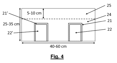
Fig. 4 discloses an end view of a cathode block with two slots for cathode
bars 22, 22',
where the cathode block 24 has a special design with a lower height and with a
wear
resistant composite material, in selected areas of the upper layer 25 thereof,
according to
the invention. The upper layer in this embodiment can be of 5 ¨ 10 cm
thickness, while the
cathode block can be of 25 ¨ 35 cm thickness. The width can be in the range 40
¨ 60 cm.
Fig. 5 discloses a side view of a cathode block 24, where the cathode block 24
has a special
design with a lower height and with a wear resistant composite material, in
selected areas
of the upper layer 25, 25' thereof according to the invention, similar to that
of Fig. 4. The
said areas are arranged at the end regions of the cathode block and being 5¨
10 cm thick
in this embodiment.
Fig. 6 discloses in an end view a cathode block rodded with two Cu-rods 50,
50', where the
cathode block 24 has a special design with a lower height and with a wear
resistant
composite material, in selected areas of the upper layer 25 thereof, according
to the
invention. The thickness of the wear resistant upper layer can be 5¨ 10 cm
while the total
height of the cathode block can be 13 ¨ 28 cm.
Fig. 7 discloses a side view of a cathode block corresponding to that of Fig.
6, where the
cathode block 24 has a special design with a lower height and with a wear
resistant
composite material, in selected areas 25, 25' of the upper layer thereof,
according to the
invention. The length of the cathode block can be in the range 300 ¨ 350 cm.
Fig. 8 discloses in an end view a cathode block 24 rodded onto a collector
plate 20. The
collector plate 20 is provided in this example with five collector elements,
30, 30' 30", 30",
30" that are in electrical contact with the collector plate 20. Preferably,
these parts are
made out of a steel quality that can easily be welded, and preferably the
parts are welded
together. A cathode block can be rodded to the collector elements, in a
similar manner as
disclosed in W02009/099335A1, where the solution may involve electric
conductive
CA 03179900 2022-10-11
WO 2021/213672 10 PCT/EP2020/061497
metallic particles. The number of collector elements at the collector plate
may differ from
five as shown, for instance one to seven or even none, where the rodding
material is
arranged as a layer between the plate and the cathode block. The cathode block
24 has a
special design with a lower height and with a wear resistant composite
material, in selected
areas 25 of the upper layer thereof, according to the invention. The thickness
of this material
can be 5 ¨ 10 cm while the total height of the cathode block can be in the
range 8 ¨ 28 cm.
The combination of rodding a collector plate with collector elements to a
cathode block
having a wear resistant composite material makes a particularly low cathode
block height
possible and is considered as a preferred embodiment of the invention.
Fig. 9 discloses a side view of a cathode block similar to that of Fig. 8,
where the cathode
block 24 has a special design with an even lower height and with a wear
resistant composite
material, in selected areas 25, 25' of the upper layer thereof, rodded onto a
collector plate
20, according to the invention.
Further description of the preferred embodiment:
An appropriate collector plate can comprise at least one horizontal current
outlet on at least
one side and/or at least one vertical metallic current outlet connected to the
collector plate.
In one embodiment, at least one thermocouple (TO) is inserted into a metallic
component
inside of or below the collector plate to be able to monitor the temperature
at that location.
In a further embodiment, it comprises at least one horizontal current outlet
on each end
being integrated with the collector plate.
In one embodiment, there is arranged at least one vertical current outlet at
the opposite side
of the collector plate than the cathode block.
In one other embodiment, at least one metallic collector element is arranged
at the upper
side of a metallic collector plate, where said collector element is embedded
in a
corresponding recess in the bottom part of the cathode block, the recess being
wider than
the collector element and being filled with an electric conductive material
comprising
conductive particles.
In another embodiment, there are one or more collector elements, preferably 3
to 7 being
separated at a distance of typically 50 mm to 150 mm.
CA 03179900 2022-10-11
WO 2021/213672 11 PCT/EP2020/061497
In still another embodiment, the at least one collector element(s) is of same
length or shorter
length than the cathode block.
Advantageously, the collector plate can have one to five inserts of materials
with higher
electric conductivity, like copper.
The present cathode design is advantageous with regard to the
magnetohydrodynamic
stability of the cell it has been installed in, it may have an improved life
cycle and less space
usage and in operation, and it also represents a low cathode voltage drop with
regard to a
conventional cathode design.
At the ends of the collector plate 20, there can be arranged horizontal
current outlets (not
shown). The horizontal current outlets can be made out of conductors of a good
conducting
material like copper or copper alloy and further being, at least at its outlet
ends, covered by
a sheet material, preferably made out of a metal such as steel. The horizontal
current
outlets with their corresponding conductors can be integrated in slots made in
the collector
plate 20. This integration may be based upon press-fit tolerances or pre-
heated plate
sections to use thermal expansion for a tight fit. However, any appropriate
fixation including
welding may be applied. The conducting material in the slots may be covered by
a protective
steel plate on the upper and lower side.
Advantageously, the whole assembly with the cathode block 24 and the collector
plate 20
are tilted somewhat during the filling procedure of the particles, to allow
the particles to fill
the recess in a smooth and complete manner. Additionally, some vibration might
be applied
to the plate or plate sections for homogeneous filling with the particles.
The recesses or slots in the bottom of the cathode block can be made in a
green condition
of the carbonaceous body by commonly used techniques or in a calcinated or
graphitized
condition by commonly available process equipment. The geometry of the slots
has to fit
the plates.
It should be understood that the electrical conducting solids or particles can
be of any
appropriate metal such as steel, iron, copper, aluminium etc., or alloys of
same. Further,
the shape of the solids can be spherical, oval or elliptic, flaked, or have
any appropriate
.. shape. The size and particle distribution may vary. The maximum size will
in general be
restricted by the width of the space to be filled. A non-homogenous
distribution of particle
CA 03179900 2022-10-11
WO 2021/213672 12 PCT/EP2020/061497
sizes may be convenient to obtain a compact filling as possible, with little
space between
the particles.
Apart from having good electrical conducting properties, the applied material
should have
good mechanical properties (crushing properties) and be able to sustain high
temperatures.
As mentioned later, magnetic properties may be advantageous.
Further, the size of said solids can be from 0,1 millimetres and close to the
minimum
opening between the carbonaceous body and conductor plate. Commonly, the size
may be
up to 2 millimetres.
Preferably there can be several thermocouples attached to or inserted into the
cathode
plate to monitor the temperature in the cathode. For instance, holes up to the
centre of the
plate can be drilled in the cathode plate at appropriate locations for
reception of
thermocouples. The steel plate creates a protective housing for the
thermocouples to
survive the chemical aggressive environment during operation.
The insertion length of the horizontal outlets can preferably be limited in
that it does not
cover the central part of the cathode plate. The length of the insertion can
for example be
designed to reflect the existence of vertical outlets in that plate, and the
path length of the
current through the conductors to the next cell. On side-by-side arranged
cells the length of
the insertion can be made longer on the upstream side to balance the current
pick-up in the
cathode block to be more balanced.
Each cathode element can be fitted with horizontal outlets only for instance
for end-to-end
arranged cells or when there is no space for busbars under the cell, or with
several
horizontal outlets and one vertical outlet. To optimize the magnetic field, a
configuration with
one or two vertical outlets only and no horizontal outlet can be possible for
some selected
cathode block of the cathode panel as well.
A combination of different collector plate configurations can be applied in
one cell to create
a favourable magnetic field from the electric current distribution or enhance
the thermal
properties of the cell by reducing the number of outlets where a heat loss is
undesired, e.g.
on the short ends of the cell which tend to be colder due to the nearby
corners. Vertical
outlets attached to only some collector plates can be beneficial to optimize
the current flow
and magnetic field. This may as well reduce the costs of the installation when
the current
distribution and magnetohydrodynamic stability of the cell is sufficient.
CA 03179900 2022-10-11
WO 2021/213672 13 PCT/EP2020/061497
The claimed collector plate cathode with the very low height cathode block has
multiple
advantages compared to a traditional design comprising a carbonaceous body
with
embedded collector bars:
- In the preferred embodiment the block will be significantly lower, due to
significantly lower erosion rate of the TiB2-Carbon composite material the
lifetime
will still be higher.
- The cathode voltage drop (CVD) is significantly lower (as low as 150mV) due
to the
low cathode block height, number of outlets, material electric properties,
better
electric contact due to initial mobility of particles, total surface of
contact resistance
and shorter current paths from the existence of vertical outlets
- The current distribution into the top cathode block surface is more
homogeneous
due to the plate geometry, conductance of insertions, and existence of
vertical
outlets, thus avoiding undesired, instability causing horizontal currents in
the liquid
aluminium pad above the cathode block surface. The higher stability of the
cell can
be used to reduce the cell voltage and energy consumption further or increase
the
amperage and production volume
- Due to the above mentioned better current distribution, the erosion of
the
carbonaceous material is more homogeneous thus increasing the life time of the
cell
- The vertical space usage of the arrangement is less than with conventional
design,
thus allowing for a lower cathode shell or ¨ if the shell height is kept, to
use the extra
space for better bottom insulation, higher and longer-lasting anode blocks, or
more
height for liquid aluminium or bath
- The design has a better ratio of electric to thermal conductivity at the
most critical
locations of high current density and heat flow, thus improving the energy
efficiency
of the cell (less heat loss and lower cathode voltage drop CVD)
- When retrofitted to an existing cell design, vertical outlets according
to the claims
may allow to raise the amperage and thus increase production per cell
- Better current distribution into the cathode surface giving improved MHD
stability
and thus options to reduce the ACD or increase the amperage level by up to 15%
CA 03179900 2022-10-11
WO 2021/213672 14 PCT/EP2020/061497
- Less heat loss because of smaller cross-section and exposed surface of HO
and
VO avoiding cold cathodes with bottom freeze, specifically if the technology
is
used to reduce energy consumption
- Lower rodding cost in embodiments where there is no cast iron
- No risk of cracking of carbon block in embodiments not using cast-in
collector bars
(cast iron)
- Flexible installation of VOs after placing of the cathode blocks in the
lining
- Better balancing of current flow to upstream/downstream/bottom side
giving better
MHD stability
- Considerably lower total height of the assembly giving space for more
thermal
bottom insulation or larger cavity. The difference could be up to 300 mm
- Easier installation of thermocouples inside the plate due to less deep
drilling than
in collector bars, or direct access from bottom side'
- Reduced amount of conventional cathode material saves costs in general,
while
the arrangement of the composite material only at selected areas where the
wear
of the surface of the cathode is expected as being most excessive, reduces the
amount of expensive wear resistant material compared to conventional designs.