Note: Descriptions are shown in the official language in which they were submitted.
WO 2021/240444
PCT/IB2021/054665
AEROSOL DELIVERY DEVICE
TECHNOLOGY FIELD
The present disclosure relates to aerosol delivery devices such as smoking
articles, and more
particularly to aerosol delivery devices that may utilize electrically
generated heat for the production of
aerosol (e.g., smoking articles commonly referred to as electronic
cigarettes). The smoking articles may be
configured to heat an aerosol precursor, which may incorporate materials that
may be made or derived from
tobacco or otherwise incorporate tobacco, the precursor being capable of
forming an inbalable substance for
human consumption.
BACKGROUND
Many smoking devices have been proposed through the years as improvements
upon, or alternatives
to, smoking products that require combusting tobacco for use. Many of those
devices purportedly have been
designed to provide the sensations associated with cigarette, cigar, or pipe
smoking, but without delivering
considerable quantities of incomplete combustion and pyrolysis products that
result from the burning of
tobacco. To this end, there have been proposed numerous smoking products,
flavor generators, and
medicinal inhalers that utilize electrical energy to vaporize or heat a
volatile material, or attempt to provide
the sensations of cigarette, cigar, or pipe smoking without burning tobacco to
a significant degree. See, for
example, the various alternative smoking articles, aerosol delivery devices,
and heat generating sources set
forth in the background art described in U.S. Pat. No. 7,726,320 to Robinson
et al., U.S. Pat. App. Pub. No.
2013/0255702 to Griffith Jr. et al., and U.S. Pat. App. Pub. No. 2014/0096781
to Sears et al., which are
incorporated herein by reference in their entireties. See also, for example,
the various types of smoking
articles, aerosol delivery devices, and electrically powered heat generating
sources referenced by brand
name and commercial source in U.S. Pat. App. Ser. No. 14/170,838 to Bless et
al., filed Febniary 3, 2014,
which is incorporated herein by reference in its entirety. It would be
desirable to provide an aerosol delivery
device with advantageous usability features.
BRIEF SUMMARY
The present disclosure relates to aerosol delivery devices and elements of
such devices. The
disclosure particularly relates to an aerosol delivery device and a cartridge
for use in an aerosol delivery
device. In this regard, various embodiments of the disclosure provide an
aerosol delivery device and/or a
cartridge suitable for use with such an aerosol delivery device.
In one or more embodiments, the present disclosure can provide a cartridge for
use in an aerosol
delivery device, the cartridge comprising: a body defining a reservoir and
defining an aerosol pathway in
fluid communication with an aerosol outlet; an air entry; an atomizer; an
aerosol forming chamber; and an
air pathway extending from the air entry, through the aerosol forming chamber,
the aerosol pathway, and the
aerosol outlet; wherein the cartridge includes one or more splitting elements
effective to split an air stream at
least once while passing through the air pathway. In additional embodiments,
the cartridge can be further
- 1 -
CA 03180409 2022- 11- 25
WO 2021/240444
PCT/IB2021/054665
defined in relation to one or more of the following statements, which
statements can be defined in any
number and/or order.
The one or more splitting elements can be positioned so that the air stream is
split prior to entering
the aerosol forming chamber.
The one or more splitting elements can be positioned so that the air stream is
split into a plurality of
air streams that are directed toward a surface of the atomizer at a plurality
of points that are laterally
positioned relative to a geometric center of the surface of the atomizer.
The atomizer can include a surface with a midline that extends from a front
edge of the atomizer to a
back edge of the atomizer and that is approximately centrally located between
a first end of the atomizer and
a second end of the atomizer, and wherein the one or more splitting elements
is positioned so that the air
stream is split into two air streams that are directed toward the surface of
the atomizer on each of two sides
of the midline.
The one or more splitting elements can comprise a wedge that is substantially
centrally located
above air entry.
The cartridge can comprise an upper frame member positioned proximate the
reservoir, a lower
frame member engaging an opening at an end of the body opposite from the
aerosol outlet, and a bottom seal
positioned in the body between the upper frame member and the lower frame
member.
The air entry can be defined in the lower frame member.
The bottom seal can include two air apertures.
The one or more splitting elements can comprise a central member positioned in
the bottom seal
between the two air apertures.
The two air apertures can be substantially symmetrically arranged relative to
the air entry.
The aerosol forming chamber can be defined between the upper frame member and
the bottom seal.
The bottom seal can comprise an island positioned between the aerosol forming
chamber and the
aerosol pathway of the body.
The island can be effective to split an aerosol stream from the aerosol
forming chamber into two
streams prior to passage of the aerosol stream into the aerosol pathway.
The bottom seal can comprise a bottom wall that defines a floor across at
least a portion of a top
surface of the bottom seal.
The floor of the bottom seal can comprise one or more components effective to
trap liquid therein.
The one or more components effective to trap liquid can comprise one or more
baffles that
individually completely surround one or more openings though the bottom seal.
The cartridge can comprise baffles that individually completely surround a
plurality of air apertures
through the bottom seal.
The bottom seal can comprise an outer edge that can be in contact with an
inner surface of an outer
wall of the tank body.
The outer edge of the bottom seal can comprise a plurality of ribs.
- 2 -
CA 03180409 2022- 11- 25
WO 2021/240444
PCT/IB2021/054665
The cartridge can include at least two separate splitting elements effective
to split the air stream at
least twice while passing through the air pathway.
The at least two separate splitting elements can be positioned in the
cartridge so that the air stream is
split in a direction that is substantially parallel to a longitudinal axis of
the cartridge and is split in a direction
that is substantially orthogonal to the longitudinal axis of the cartridge.
The atomizer can comprise a heater.
The atomizer further can comprise a liquid transport element.
In further embodiments, the present disclosure can provide a cartridge for use
in an aerosol delivery
device. In particulate, the cartridge can comprise: a body defining a
reservoir and defining an aerosol
pathway in fluid communication with an aerosol outlet; an air entry; a
splitter configured to split air entering
the air entry into a plurality of air passages; a heater; and an aerosol
forming chamber where air from the
plurality of air passages is configured to mix with vapor formed by the heater
to form an aerosol, the aerosol
forming chamber being in fluid connection with the aerosol pathway.
In still further embodiments, a cartridge for use in an aerosol delivery
device can comprise: a body
including an outer wall and defining a reservoir, an aerosol pathway in fluid
communication with an aerosol
outlet, and an opening at a bottom end thereof, the opening being defined by
the outer wall; and a sealing
member positioned within the body between the reservoir and the opening at the
bottom of the body, the
sealing member having an outer edge that is in contact with an inner surface
of the outer wall of the body,
wherein the scaling member includes a bottom wall with at least one aperture
therethrough, the at least one
aperture being surrounded by a baffle that extends upward from the bottom
wall.
In one or more embodiments, the present disclosure further can provide methods
for forming a
cartridge for an aerosol delivery device. For example, such method can
comprise: performing a first
injection molding step with a first polymeric material, the first injection
molding step being effective to form
a body defining at least a reservoir and an aerosol pathway separated from the
reservoir; and performing a
second injection molding step with a second polymeric material.that differs
from the first polymeric material
in at least one aspect, the second injection molding step being effective to
cover at least a portion of the body
with a layer of the second polymeric material. For example, the first
polymeric material can be transparent
or translucent, and the second polymeric material can be opaque or colored.
Further, the method can include
adding a framing component to a mouthend of the body after performing the
first injection molding step and
prior to performing the second injection molding step.
The present disclosure includes, without limitation, the following
embodiments.
Embodiment 1: A cartridge for use in an aerosol delivery device, the cartridge
comprising: a body
defining a reservoir and defining an aerosol pathway in fluid communication
with an aerosol outlet; an air
entry; an atomizer; an aerosol forming chamber; and an air pathway extending
from the air entry, through
the aerosol forming chamber, the aerosol pathway, and the aerosol outlet;
wherein the cartridge includes one
or more splitting elements effective to split an air stream at least once
while passing through the air pathway.
Embodiment 2: The cartridge of Embodiment 1, wherein the one or more splitting
elements is
positioned so that the air stream is split prior to entering the aerosol
forming chamber.
-3 -
CA 03180409 2022- 11- 25
WO 2021/240444
PCT/IB2021/054665
Embodiment 3: The cartridge of any of Embodiments 1 and 2, wherein the one or
more splitting
elements is positioned so that the air stream is split into a plurality of air
streams that are directed toward a
surface of the atomizer at a plurality of points that are laterally positioned
relative to a geometric center of
the surface of the atomizer.
Embodiment 4: The cartridge of any of embodiments 1 to 3, wherein the atomizer
includes a surface
with a midline that extends from a front edge of the atomizer to a back edge
of the atomizer and that is
approximately centrally located between a first end of the atomizer and a
second end of the atomizer, and
wherein the one or more splitting elements is positioned so that the air
stream is split into two air streams
that are directed toward the surface of the atomizer on each of two sides of
the miclline.
Embodiment 5: The cartridge of any of embodiments 1 to 4, wherein the one or
more splitting
elements comprises a wedge that is substantially centrally located above air
entry.
Embodiment 6: The cartridge of any of embodiments 1 to 5, wherein the
cartridge comprises an
upper frame member positioned proximate the reservoir, a lower frame member
engaging an opening at an
end of the body opposite from the aerosol outlet, and a bottom seal positioned
in the body between the upper
frame member and the lower frame member.
Embodiment 7: The cartridge of any of embodiments 1 to 6, wherein the air
entry is defined in the
lower frame member.
Embodiment 8: The cartridge of any of embodiments 1 to 7, wherein the bottom
seal includes two
air apertures.
Embodiment 9: The cartridge of any of embodiments 1 to 8, wherein the one or
more splitting
elements comprises a central member positioned in the bottom seal between the
two air apertures.
Embodiment 10: The cartridge of any of embodiments 1 to 9, wherein the two air
apertures are
substantially symmetrically arranged relative to the air entry.
Embodiment 11: The cartridge of any of embodiments 1 to 10, wherein the
aerosol forming chamber
is defined between the upper frame member and the bottom seal.
Embodiment 12: The cartridge of any of embodiments 1 to 11, wherein the bottom
seal comprises
an island positioned between the aerosol forming chamber and the aerosol
pathway of the body.
Embodiment 13: The cartridge of any of embodiments 1 to 12, wherein the island
is effective to split
an aerosol stream from the aerosol forming chamber into two streams prior to
passage of the aerosol stream
into the aerosol pathway.
Embodiment 14: The cartridge of any of embodiments 1 to 13, wherein the bottom
seal comprises a
bottom wall that defines a floor across at least a portion of a top surface of
the bottom seal.
Embodiment 15: The cartridge of any of embodiments 1 to 14, wherein the floor
of the bottom seal
comprises one or more components effective to trap liquid therein.
Embodiment 16: The cartridge of any of embodiments 1 to 15, wherein the one or
more components
effective to trap liquid comprise one or more baffles that individually
completely surround one or more
openings though the bottom seal.
- 4 -
CA 03180409 2022- 11- 25
WO 2021/240444
PCT/IB2021/054665
Embodiment 17: The cartridge of any of embodiments 1 to 16, comprising baffles
that individually
completely surround a plurality of air apertures through the bottom seal.
Embodiment 18: The cartridge of any of embodiments 1 to 17, wherein the bottom
seal comprises
an outer edge that is in contact with an inner surface of an outer wall of the
tank body.
Embodiment 19: The cartridge of any of embodiments 1 to 18, wherein the outer
edge of the bottom
seal comprises a plurality of ribs.
Embodiment 20: The cartridge of any of embodiments 1 to 19, wherein the
cartridge includes at
least two separate splitting elements effective to split the air stream at
least twice while passing through the
air pathway.
Embodiment 21: The cartridge of any of embodiments 1 to 20, wherein the at
least two separate
splitting elements are positioned in the cartridge so that the air stream is
split in a direction that is
substantially parallel to a longitudinal axis of the cartridge and is split in
a direction that is substantially
orthogonal to the longitudinal axis of the cartridge.
Embodiment 22: The cartridge of any of embodiments 1 to 21, wherein the
atomizer comprises a
heater.
Embodiment 23: The cartridge of any of embodiments 1 to 22, wherein the
atomizer further
comprises a liquid transport element.
Embodiment 24: A cartridge for use in an aerosol delivery device, the
cartridge comprising: a body
including an outer wall and defining a reservoir, an aerosol passage in fluid
communication with an aerosol
outlet, and an opening at a bottom end thereof, the opening being defined by
the outer wall; and a sealing
member positioned within the tank body between the reservoir and the opening
at the bottom of the tank
body, the sealing member having an outer edge that is in contact with an inner
surface of the outer wall of
the tank body, wherein the sealing member includes a bottom wall with at least
one aperture therethrough,
the at least one aperture being surrounded by a baffle that extends upward
from the bottom wall.
These and other features, aspects, and advantages of the disclosure will be
apparent from a reading
of the following detailed description together with the accompanying drawings,
which are briefly described
below. The disclosure includes any combination of elements, components, and
features that are described
herein, regardless of whether such elements, components, and features are
expressly combined in a specific
embodiment description herein. This disclosure is intended to be read
holistically such that any separable
features, components, or elements of the disclosure, in any of its various
aspects and embodiments, should
be viewed as intended to be combinable unless the context clearly dictates
otherwise.
BRIEF DESCRIPTION OF THE FIGURES
Having thus described the disclosure in the foregoing general terms, reference
will now be made to
the accompanying drawings, which are not necessarily drawn to scale, and
wherein:
FIG. 1 illustrates a perspective view of an aerosol delivery device, according
to example
implementations of the present disclosure.
- 5 -
CA 03180409 2022- 11- 25
WO 2021/240444
PCT/IB2021/054665
FIG. 2 illustrates a perspective view of a control device of an aerosol
deliveiy device, according to
example implementations of the present disclosure.
FIG. 3 illustrates an exploded perspective view of a control device of an
aerosol delivery device,
according to an example implementation of the present disclosure.
FIG. 4A illustrates a front view of a control device of an aerosol delivery
device, according to an
example implementation of the present disclosure.
FIG. 4B illustrates a corresponding section view of the control device of FIG.
4A, according to an
example implementation of the present disclosure.
FIG. 5A illustrates a side view of a control device of an aerosol delivery
device, according to an
example implementation of the present disclosure.
FIG. 5B illustrates a corresponding section view of the control device of FIG.
5A, according to an
example implementation of the present disclosure.
FIG. 6 illustrates a perspective partial section view of a control device of
an aerosol delivery device,
according to an example implementation of the present disclosure.
FIG. 7 illustrates an exploded perspective view of a cartridge of an aerosol
delivery device,
according to an example implementation of the present disclosure.
FIG. 8 illustrates a partial cross-sectional view of a cartridge body
according to an example
implementation of the present disclosure.
FIG. 9 illustrates a partial cross-sectional view of a cartridge according to
an example
implementation of the present disclosure.
DETAILED DESCRIPTION
The present disclosure will now be described more fully hereinafter with
reference to example
embodiments thereof. These example embodiments are described so that this
disclosure will be thorough
and complete, and will fully convey the scope of the disclosure to those
skilled in the art. Indeed, the
disclosure may be embodied in many different forms and should not be construed
as limited to the
embodiments set forth herein; rather, these embodiments are provided so that
this disclosure will satisfy
applicable legal requirements. As used in the specification, and in the
appended claims, the singular fonus
-a-, -an", "the-, include plural referents unless the context clearly dictates
otherwise.
As described hereinafter, embodiments of the present disclosure relate to
aerosol delivery devices or
vaporization devices, said terms being used herein interchangeably. Aerosol
delivery devices according to
the present disclosure use electrical energy to heat a material (preferably
without combusting the material to
any significant degree and/or without significant chemical alteration of the
material) to form an inhalable
substance; and components of such devices have the form of articles that most
preferably are sufficiently
compact to be considered hand-held devices. That is, use of components of
preferred aerosol delivery
devices does not result in the production of smoke ¨ i.e., from by-products of
combustion or pyrolysis of
tobacco, but rather, use of those preferred systems results in the production
of vapors resulting from
volatilization or vaporization of certain components incorporated therein. In
preferred embodiments,
- 6 -
CA 03180409 2022- 11- 25
WO 2021/240444
PCT/IB2021/054665
components of aerosol delivery devices may be characterized as electronic
cigarettes, and those electronic
cigarettes most preferably incorporate tobacco and/or components derived from
tobacco, and hence deliver
tobacco derived components in aerosol form.
Aerosol delivery devices may provide many of the sensations (e.g., inhalation
and exhalation rituals,
types of tastes or flavors, organoleptic effects, physical feel, use rituals,
visual cues such as those provided
by visible aerosol, and the like) of smoking a cigarette, cigar, or pipe that
is employed by lighting and
burning tobacco (and hence inhaling tobacco smoke), without any substantial
degree of combustion of any
component thereof. For example, the user of an aerosol generating device of
the present disclosure can hold
and use that piece much like a smoker employs a traditional type of smoking
article, draw on one end of that
piece for inhalation of aerosol produced by that piece, take or draw puffs at
selected intervals of time, and
the like.
Aerosol delivery devices of the present disclosure also can be characterized
as being vapor-
producing articles or medicament delivery articles. Thus, such articles or
devices can be adapted so as to
provide one or more substances (e.g., flavors and/or pharmaceutical active
ingredients) in an inhalable form
or state. For example. inhalable substances can be substantially in the form
of a vapor (i.e., a substance that
is in the gas phase at a temperature lower than its critical point).
Alternatively, inhalable substances can be
in the form of an aerosol (i.e., a suspension of fine solid particles or
liquid droplets in a gas). For purposes
of simplicity, the term "aerosol" as used herein is meant to include vapors,
gases, and aerosols of a form or
type suitable for human inhalation, whether or not visible, and whether or not
of a form that might be
considered to be smoke-like.
Aerosol delivery devices of the present disclosure most preferably comprise
some combination of a
power source (i.e., an electrical power source), at least one control
component (e.g., means for actuating,
controlling, regulating and ceasing power for heat generation, such as by
controlling electrical current flow
from the power source to other components of the article ¨ e.g., a
microcontroller or microprocessor), a
heater or heat generation member (e.g., an electrical resistance heating
element or other component, which
alone or in combination with one or more further elements may be commonly
referred to as an "atomizer"),
a liquid composition (e.g., commonly an aerosol precursor composition liquid
capable of yielding an aerosol
upon application of sufficient heat, such as ingredients commonly referred to
as "smoke juice," "e-liquid"
and -e-juice-), and a mouthpiece or mouth region for allowing draw upon the
aerosol delivery device for
aerosol inhalation (e.g., a defined airflow path through the article such that
aerosol generated can be
withdrawn therefrom upon draw). In some embodiments, an aerosol delivery
device can be a power unit or
control unit, which unit typically comprises at least a power source and a
control component. In some
embodiments, an aerosol delivery device can be a cartridge or pod that can
typically comprise at least
atomizer components, a reservoir suitable for storage of liquid, and a
mouthpiece or mouth region. In some
embodiments, an aerosol delivery device can be a combination of a power unit
or control unit with a
cartridge or pod.
More specific formats, configurations and arrangements of components within
the aerosol delivery
devices of the present disclosure will be evident in light of the further
disclosure provided hereinafter.
- 7 -
CA 03180409 2022- 11- 25
WO 2021/240444
PCT/IB2021/054665
Additionally, the selection and arrangement of various aerosol delivery device
components can be
appreciated upon consideration of the commercially available electronic
aerosol delivery devices, such as
those representative products referenced in the background art section of the
present disclosure.
An example implementation of an aerosol delivery device 100 of the present
disclosure is shown in
FIG. 1. As illustrated, the aerosol delivery device 100 includes a
control/power device 200 and a removable
cartridge/pod 300. Although only one cartridge is shown in the depicted
implementation, it should be
understood that, in various implementations, the aerosol delivery device 100
may comprise an
interchangeable system. For example, in one or more implementations, a single
control device may be
usable with a plurality of different cartridges. Likewise, in one or more
implementations, a single cartridge
may be usable with a plurality of different control devices.
FIG. 2 illustrates a perspective view of a further embodiment of the control
device 200, and FIG. 3
illustrates an exploded perspective view thereof. FIG 4A, FIG. 4B, FIG. 5A,
and FIG. 5B illustrate further
views of the control device. The figures in total illustrate that the control
device 200 can be provided in a
variety of form factors while still incorporating similar internal components.
Thus, it is understood that the
components illustrated in FIG. 2 through FIG. 5B may be utilized with the form
factor illustrated in FIG. 1
as well as other form factors that may be envisioned.
As shown in the figures, the control device 200 of the depicted implementation
generally includes a
housing 202 defining an outer wall 204, an upper frame 206, an upper frame
seal 208, a pressure sensor seal
210, a lower frame 212, a control component 214, a battery 216, a vibration
motor 218, a motor housing
220, a pin seal 222, an end cap 224, and a light diffuser 226. The upper frame
206 of the control device 200
defines a cartridge receiving chamber 230 within which a cartridge may be
coupled. The control device 200
also includes a pair of opposite windows 232 that are defined through the
outer wall 204 of the housing 202,
as well as through the upper frame 206. In alternative embodiments, the
windows 232 may be positioned
below the upper frame 206. It thus will be appreciated that the illustrated
windows 232 are provided by way
of example and not by way of limitation. For example, alternative
implementations may include a window
having a different shape than that illustrated. As another example, some
implementations may include only
a single window. In still other implementations, there need not be any
windows. In the depicted
implementation, the upper frame 206 and the housing 202 represent different
parts; however, in other
implementations, the upper frame and the housing may be continuously formed
such that they comprise the
same part.
In the depicted implementation, the housing 202 comprises a metal material,
such as, for example,
aluminum; however, in other implementations the housing may comprise a metal
alloy material, and in still
other implementations the housing may comprise a molded plastic material. In
the depicted implementation,
one or more of the housing 202, upper frame 206, lower frame 212, and end cap
224 may be made of a
molded polymer material, such as, for example, a molded plastic material
(e.g., polybutylene terephthalate
(PBT), acrylonitrile butadiene styrene (ABS), polyethylene, polycarbonate,
Polyamide (Nylon), high impact
polystyrene, polypropylene, and combinations thereof). In other
implementations, one or more of these
components may be made of other materials, including, for example, metal
materials (e.g., aluminum,
- 8 -
CA 03180409 2022- 11- 25
WO 2021/240444
PCT/IB2021/054665
stainless steel, metal alloys, etc.), glass materials, ceramic materials
(e.g., alumina, silica, mullite, silicon
carbide, silicon nitride, aluminum nitride, etc.), composite materials, and/or
any combinations thereof.
In the depicted implementation, the lower frame 212 is configured to contain
the battery 216 in an
interior area thereof. In the depicted implementation, the battery may
comprise a lithium polymer (LiPo)
battery; however various other batteries may be suitable. Some other examples
of batteries that can be used
according to the disclosure are described in U.S. Pat. App. Pub. No.
2010/0028766 to Peckerar et al., the
disclosure of which is incorporated herein by reference in its entirety. In
some implementations, other types
of power sources may be utilized. For example, in various implementations a
power source may comprise a
replaceable battery or a rechargeable batteiy, solid-state battery, thin-film
solid-state battery, rechargeable
supercapacitor or the like, and thus may be combined with any type of
recharging technology, including
connection to a wall charger, connection to a car charger (e.g., cigarette
lighter receptacle, USB port, etc.),
connection to a computer, such as through a universal serial bus (USB) cable
or connector (e.g., USB 2.0,
3.0, 3.1, USB Type-C), connection to a USB connector (e.g., USB 2.0, 3.0, 3.1,
USB Type-C as may be
implemented in a wall outlet, electronic device, vehicle, etc.), connection to
a photovoltaic cell (sometimes
referred to as a solar cell) or solar panel of solar cells, a wireless
chargcr, such as a charger that uses
inductive wireless charging (including for example, wireless charging
according to the Qi wireless charging
standard from the Wireless Power Consortium (WPC)), or a wireless radio
frequency (RF) based charger,
and connection to an array of external cell(s) such as a power bank to charge
a device via a USB connector
or a wireless charger. An example of an inductive wireless charging system is
described in U.S. Pat App.
Pub. No. 2017/0112196 to Sur et al., which is incorporated herein by reference
in its entirety. In further
implementations, a power source may also comprise a capacitor. Capacitors are
capable of discharging
more quickly than batteries and can be charged between puffs, allowing the
battery to discharge into the
capacitor at a lower rate than if it were used to power the heating member
directly. For example, a
supercapacitor ¨ e.g., an electric double-layer capacitor (EDLC) ¨ may be used
separate from or in
combination with a battery. When used alone, the supercapacitor may be
recharged before each use of the
article. Thus, the device may also include a charger component that can be
attached to the smoking article
between uses to replenish the supercapacitor. Examples of power supplies that
include supercapacitors are
described in U.S. Pat. App. Pub. No. 2017/0112191 to Sur et al., which is
incorporated herein by reference
in its entirety.
The aerosol delivery device 100 of the depicted implementation includes a
control mechanism in the
form of the control component 214, which is configured, in part, to control
the amount of electric power
provided to the heating member of the cartridge 300. Although other
configurations are possible, the control
component 214 of the depicted implementation comprises a circuit board 234
(e.g., a printed circuit board
(PCB)) that includes both rigid and flexible portions. In particular, the
circuit board 234 of the depicted
implementation includes a rigid central section 215 and two rigid end sections
comprising a proximal end
section 217 and a distal end section 219, with each of the end sections 217,
219 being connected to the
central section 215 by a respective flexible connection. In such a manlier,
when the lower frame 212, battery
216, and circuit board 234 are assembled into the control device 200, the
central section 215 of the circuit
- 9 -
CA 03180409 2022- 11- 25
WO 2021/240444
PCT/IB2021/054665
board 234 is configured to be disposed proximate a major surface of the
battery 216, and the two end
sections 217, 219 are configured to be disposed substantially perpendicular to
the central section 215 (e.g.,
"substantially" indicating exactly perpendicular or within +1-5 degrees, 4
degrees, 3 degrees, 2 degrees, or 1
degree of exactly perpendicular). In particular, the proximal end section 217
of the circuit board 234 is
configured to extend over the top of the lower frame 212, and the distal end
section 219 is configured to
extend over the bottom of the lower frame 212. The lower frame 212 of the
control device 200 is also
configured to contain the motor housing 220, into which the vibration motor
218 is received. In various
implementations, the vibration motor 218 may provide haptic feedback relating
to various operations of the
device 100.
The central section 215 of the depicted implementation also includes an
indicator in the form of a
light source 221. In some implementations, the light source may comprise, for
example, at least one light
emitting diode (LED) capable of providing one or more colors of light. In
other implementations, the light
source may be configured to illuminate in only one color, while in other
implementations, the light source
may be configured to illuminate in variety of different colors. In still other
implementations, the light source
may be configured to provide white light. In the depicted implementation, the
light source 221 comprises an
RGB (red, green, blue) LED that is configured to provide a variety of colors
of light, including white light.
The central section 215 of the depicted circuit board 234 also includes
electrical contacts 223 that are
configured to operatively connect the circuit board 234 to the vibration motor
218. Other types of electronic
components, structures and configurations thereof, features thereof, and
general methods of operation
thereof, are described in U.S. Pat. Nos. 4,735,217 to Gerth et al.; 4,947,874
to Brooks et at.; 5,372,148 to
McCafferty et al.; 6,040,560 to Fleischhauer et al.; 7,040,314 to Nguyen et
al. and 8,205,622 to Pan; U.S.
Pat. App. Pub. Nos. 2009/0230117 to Fernando et al., 2014/0060554 to Collet et
al., and 2014/0270727 to
Ampolini et al.; and U.S. Pat. App. Pub. No. 2015/0257445 to Henry et al.;
which are incorporated herein by
reference. Yet other features, controls or components that can be incorporated
into aerosol delivery devices
of the present disclosure are described in U.S. Pat. Nos. 5,967,148 to Harris
et al.; 5,934,289 to Watkins et
al.; U.S. Pat. No. 5,954,979 to Counts et al.; 6,040,560 to Fleischhauer et
al.; 8,365,742 to Hon; 8,402.976 to
Fernando et al.; U.S. Pat. App. Pub. Nos. 2010/0163063 to Fernando et al.;
2013/0192623 to Tucker et al.;
2013/0298905 to Leven et al.; 2013/0180553 to Kim et al., 2014/0000638 to
Sebastian et al., 2014/0261495
to Novak et al., and 2014/0261408 to DePiano et al.; which are incorporated
herein by reference in their
entireties.
In the depicted implementation, the light source 221 is covered by the light
diffuser 226, a portion of
which is configured to be received by the end cap 224. In such a manner, when
assembled, the light diffuser
226 is positioned in or proximate an aperture 225 defined in the outer wall
204 of the housing 202 and
proximate a distal end thereof. In the depicted implementation, the aperture
225 comprises a narrow,
elongate opening; however, in other implementations, the aperture may be
provided in any desired shape and
may be positioned at any location on the control device 200. In some
implementations, the light diffuser
226 may comprise a transparent or translucent member configured to allow a
user to view the light source
221 from the outside of the housing 202. In the depicted implementation, the
light diffuser 226 may be
- 10 -
CA 03180409 2022- 11- 25
WO 2021/240444
PCT/IB2021/054665
made of a molded polymer material, such as, for example, a molded plastic
material (e.g., acrylonitrile
butadiene styrene (ABS), polyethylene, polycarbonate, Polyamide (Nylon), high
impact polystyrene,
polypropylene, and combinations thereof), although other materials, including
glass, arc possible. In various
implementations, further indicators (e.g., other haptic feedback components,
an audio feedback component,
or the like) can be included in addition to or as an alternative to the
indicators included in the depicted
implementation. Additional representative types of components that yield
visual cues or indicators, such as
LED components. and the configurations and uses thereof, are described in U.S.
Pat. Nos. 5,154,192 to
Sprinkel et al.; 8,499,766 to Newton and 8,539,959 to Scattenlay; U.S. Pat.
App. Pub. No. 2015/0020825 to
Galloway et al.; and U.S. Pat. App. Pub. No. 2015/0216233 to Sears et al.;
which are incorporated herein by
reference in their entireties. While FIG. 1 through and FIG. 3 illustrate both
a window 232 and an aperture
225, it is understood that only one or the other may be present. For example,
only aperture 225 may be
present. Thus, it is understood that the light source 221 and any other
appropriate component of the control
device 200 may be positioned according to the form factor of the housing 202.
Although other configurations are possible, the proximal end section 217 of
the circuit board 234 of
the depicted implementation includes a pair of conductive pins 236A, 236B, as
well as a pressure sensor
240. In the depicted implementation, the conductive pins 236A, 236B comprise
spring-loaded pins (e.g.,
electrical pogo pins) that extend through the upper frame 206 such that
portions of the ends of the pins
236A, 236B extend into the cartridge receiving chamber 230 and are biased in
that position due to the force
of the internal springs of the conductive pins 236A, 236B. In such a manner,
when a cartridge is coupled
with the control device 200, the conductive pins 236A, 236B are configured to
contact corresponding
features of the cartridge and deflect downward (e.g., toward the lower frame
212) against the force of the
springs, thus operatively connecting the installed cartridge with the control
component 214 and the battery
216. In the depicted implementation, the conductive pins 236A, 236B comprise
gold plated metal pins;
however, other materials or combinations of materials, which may also include
coatings and/or platings of
electrically conductive materials, are possible. Examples of electrically
conductive materials, include, but
are not limited to, copper, aluminum, platinum, gold, silver, iron, steel,
brass, bronze, graphite, conductive
ceramic materials, and/or any combination thereof. Although other profiles are
possible, the ends of the
conductive pins 236A, 236B of the depicted implementation have a rounded
profile such that deflection of
the conductive pins 236A, 236B is facilitated when a cartridge is inserted
into the cartridge receiving
chamber 230. In other implementations, the conductive pins may be positioned
in other locations of the
cartridge receiving chamber 230, such as, for example, proximate the top of
the cartridge receiving chamber
230. In other implementations, the conductive pins may be positioned at a
point on the sides of the upper
frame 206 between the proximal end of the outer housing 202 and the bottom
wall of the upper frame 206.
Further, in still other implementations the conductive pins may be positioned
between a midpoint of the
sidewalls and the proximal end of the outer housing 202 (i.e., in an upper
half of the sidewalls).
Alternatively, the conductive pins may be positioned between a midpoint of the
sidewalls and the bottom
wall of the inner frame wall (e.g., in a lower half of the sidewalls).
Moreover, in still other implementations,
the conductive pins may be present at any position of the upper frame 206.
- 11 -
CA 03180409 2022- 11- 25
WO 2021/240444
PCT/IB2021/054665
In various implementations, the aerosol delivery device 100 may include an
airflow sensor, pressure
sensor, or the like. As noted above, the control component 214 of the depicted
implementation includes a
pressure sensor 240, which is positioned proximate and below the cartridge
receiving chamber 230. The
position and function of the pressure sensor 240 of the depicted
implementation will be described below;
however, in other implementations an airflow or pressure sensor may be
positioned anywhere within the
control device 200 so as to subject to airflow and/or a pressure change that
can signal a draw on the device
and thus cause the battery 216 to delivery power to the heating member of the
cartridge 300. Various
configurations of a printed circuit board and a pressure sensor, for example,
are described in U.S. Pat. Pub.
No. 2015/0245658 to Worm et al., the disclosure of which is incorporated
herein by reference in its entirety.
In the absence of an airflow sensor, pressure sensor, or the like, an aerosol
delivery device may be activated
manually. such as via a pushbutton that may be located on the control device
and/or the cartridge. For
example, one or more pushbuttons may be used as described in U.S. Pat. App.
Pub. No. 2015/0245658 to
Worm et al., which is incorporated herein by reference in its entirety.
Likewise, a touchscreen may be used
as described in U.S. Pat. App. Ser. No. 14/643,626, filed March 10, 2015, to
Sears et al., which is
incorporated herein by reference in its entirety. As a further example,
components adapted for gesture
recognition based on specified movements of the aerosol delivery- device may
be used as an input. See U.S.
Pat. App. Pub. No. 2016/0158782 to Henry et al., which is incorporated herein
by reference in its entirety.
Although not included in the depicted implementation, some implementations may
include other
types of input elements, which may replace or supplement an airflow or
pressure sensor. The input may be
included to allow a user to control functions of the device and/or for output
of information to a user. Any
component or combination of components may be utilized as an input for
controlling the function of the
device. In some implementations, an input may comprise a computer or computing
device, such as a
smartphone or tablet. In particular, the aerosol delivery device may be wired
to the computer or other
device, such as via use of a USB cord or similar protocol. The aerosol
delivery device may also
communicate with a computer or other device acting as an input via wireless
communication. See, for
example, the systems and methods for controlling a device via a read request
as described in U.S. Pat. App.
Pub. No. 2016/0007561 to Ampolini et al., the disclosure of which is
incorporated herein by reference in its
entirety. In such embodiments, an APP or other computer program may be used in
connection with a
computer or other computing device to input control instructions to the
aerosol delivery device, such control
instructions including, for example, the ability to form an aerosol of
specific composition by choosing the
nicotine content and/or content of further flavors to be included. Additional
representative types of sensing
or detection mechanisms, structure and configuration thereof, components
thereof, and general methods of
operation thereof, are described in U.S. Pat. Nos. 5,261,424 to Sprinkel, Jr.;
5,372,148 to McCafferty et al.;
and PCT WO 2010/003480 to Flick; which are incorporated herein by reference in
their entireties.
In the depicted implementation, the pressure sensor seal 210 is configured to
cover the pressure
sensor 240 to protect it from any liquid and/or aerosol from an installed
cartridge. In addition, the pressure
sensor seal 210 of the depicted implementation is configured to seal the
conductive pins 236A, 236B. In
such a manner, the pressure sensor seal 210 of the depicted implementation may
be made of silicone rubber,
- 12 -
CA 03180409 2022- 11- 25
WO 2021/240444
PCT/IB2021/054665
boron nitride (BN) rubber, natural rubber, thermoplastic polyurethane, or
another resilient material. In the
depicted implementation, the upper frame seal 208 is configured to be
positioned proximate and above the
pressure sensor seal 210, such that a pair of upper frame seal tubes 209A,
209B (see FIG. 6) of the upper
frame seal 208 extend through the upper frame 206 and into the cartridge
receiving chamber 230. The upper
frame seal 208 of the depicted implementation may also be made of a silicone,
thermoplastic polyurethane,
or another resilient material.
Although other configurations are possible, the distal end section 219 of the
circuit board 234
includes the external connection element 238. In various implementations, the
external connection element
238 may be configured for connecting to an external connector and/or a docking
station or other power or
data source. For example, in some implementations an external connector may
comprise first and second
connector ends that may be interconnected by a union, which may be, for
example, a cord of variable length.
In some implementations, the first connector end may be configured for
electrical and, optionally,
mechanical connection with the device (100,200), and the second connector end
may be configured for
connection to a computer or similar electronic device or for connection to a
power source. An adaptor
including a USB connector at one end and a power unit connector at an opposing
end is disclosed in U.S.
Pat. App. Pub. No. 2014/0261495 to Novak et al., which is incorporated herein
by reference in its entirety.
In the depicted implementation, the pin seal 222 is configured to seal the
interface between the external
connection element 238 and the end cap 224. In such a manner, the pin seal 222
of the depicted
implementation may be made of a silicone, thermoplastic polyurethane, or
another resilient material. In the
depicted implementation, one or more pins of the external connection element
238 may extend through the
end cap 224 of the control device as noted above.
In various implementations, the control device may include one or more
components configured to
meet battery outgassing requirements under UL 8139. For example, the control
device may include an end
cap configured to eject in the event that sudden pressurization occurs within
the control device enclosure. in
one implementation, the end cap may include retaining pins that extend
substantially perpendicularly from a
wall of the end cap (with "substantially" having a meaning as already
described above). The retaining pins
may be configured to mate with receiving features (e.g., holes) in a frame of
the control device to establish a
friction fit or press fit that may be overcome if an internal pressure within
the control device housing
exceeds a defined internal pressure.
FIG. 6 illustrates a perspective partial section view of a control device of
an aerosol delivery device.
In particular, FIG. 6 illustrates a partial section view of the housing 202,
upper frame 206, upper frame seal
208, pressure sensor seal 210, pressure sensor 240, and lower frame 212 of the
control device 200. As
shown in the figure, a portion of the conductive pins 236A, 236B of the
control component 214 extend
through the upper frame 206. In particular, a portion of the conductive pins
236A, 236B of the depicted
implementation, which as noted above comprise spring-loaded contacts, extend
through a recessed surface
244 of the upper frame 206 and into the cartridge receiving chamber 230. In
addition, a portion of the upper
frame seal tubes 209A, 209B (which define respective seal tube channels 211A,
211B) of the upper frame
seal 208 extend through the upper frame 206 and are exposed in the cartridge
receiving chamber 230. As
- 13 -
CA 03180409 2022- 11- 25
WO 2021/240444
PCT/IB2021/054665
will be described in more detail below, regardless of the orientation of an
installed cartridge, the conductive
pins 236A, 236B and one of the upper frame seal tubes 209A, 209B are
configured to substantially align
with corresponding features of an installed cartridge. It is understood,
however, that the positions of these
components and the number of each component included in the control device can
vary as desired to
substantially match a cartridge as further defined herein.
As also shown in the figure, the upper frame 206 includes a pair of magnets
246A, 246B that are
also exposed in the cartridge receiving chamber 230. In various
implementations, the magnets 246A, 246B
may comprise any type of magnets, including rare earth magnets. For example,
in some implementations,
one or more of the magnets may comprise Neodymium magnets (also known as
NdFeB, NIB, or Neo
magnets). In various implementations, different grades of Neodymium magnets
may be used, including, for
example, N35, N38, N40, N42, N45, N48, N50, and/or N52 grades. In other
implementations, one or more
of the magnets may comprise Samarium Cobalt magnets (also known as SmCo
magnets). In still other
implementations, one or more of the magnets may comprise Ceramic/Ferrite
magnets. In other
implementations, one or more of the magnets may comprise Aluminum-Nickel-
Cobalt (AlNiCo) magnets.
In any of the foregoing implementations, one or more of the magnets may be
plated and/or coated. For
example, in some implementations, one or more of the magnets may be coated
with nickel. In other
implementations, one or more magnets may be coated with one or more of zinc,
tin, copper, epoxy, silver
and/or gold. In some implementations, one or more of the magnets may be coated
with combinations of
these materials. For example, in one implementation, one or more of the
magnets may be coated with
nickel, copper, and nickel again. In another implementation, one or more of
the magnets may be coated with
nickel, copper, nickel, and a top coating of gold.
In the depicted implementation, each magnet 246A, 246B is substantially
surrounded by a respective
location feature 248A, 248B of the upper frame 206, wherein the location
features 248A, 248B also extend
into the cartridge receiving chamber 230. Likewise, each upper frame seal tube
209A, 209B of the upper
frame seal 208 is substantially surrounded by a respective location feature
250A, 250B. As will be
discussed in more detail below, one or more of the location features 248A,
248B, 250A, 250B of the upper
frame 206 are configured as stopping or vertical locating features for an
installed cartridge and are thus
configured to position the cartridge 300 with respect to the recessed surface
244 of the upper frame 206 of
the control device 200. It is again understood that the position and/or number
of magnets and corresponding
components in the control device may vary.
As noted above, a portion of the cartridge 300 is configured to be coupled
with the cartridge
receiving chamber 230 of the inner frame 206 of the control device 200 such
that mechanical and electrical
connections are created between the cartridge 300 and the control device 200.
In particular, when the
cartridge 300 of the depicted implementation is coupled with the upper frame
206 of the control device 200,
a magnetic connection is created between the magnets 246A, 246B located in the
upper frame 206 and
corresponding features of the cartridge 300. In addition, when the cartridge
300 of the depicted
implementation is coupled with the inner frame 206, an electrical connection
is created between the pair
conductive pins 236A, 236B of the control device 200 and corresponding
features of the cartridge 300. As
- 14 -
CA 03180409 2022- 11- 25
WO 2021/240444
PCT/IB2021/054665
such, when the cartridge 300 is received in the receiving chamber 230 of the
control device 200, the
cartridge 300 may be operatively connected to the control component 214 and
the battery 216 of the control
device 200. Thus, when the cartridge 300 of the depicted implementation is
coupled with the control device
200, the cartridge 300 is mechanically biased into connection with the control
device 200 such that electrical
connection is maintained between the cartridge and the control device. It
should be understood that for the
purposes of the present disclosure, the term "operatively connected" and other
related forms thereof should
be interpreted broadly so as to encompass components that are directly
connected and/or connected via one
or more additional components.
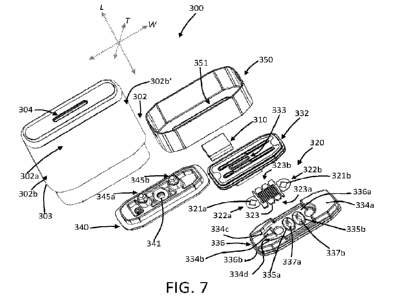
FIG. 7 illustrates an exploded view of the cartridge. Although other
configurations are possible, the
cartridge 300 of the depicted implementation generally includes a tank body
302 with an aerosol outlet 304
formed in a mouthend thereof. FIG. 8 shows a cross-sectional view of the tank
body 302. The term "tank
body" is not intended to be limiting, and it is understood that the term -
body" can be used interchangeably
with the term "tank body- without departing from the original use of the term.
Likewise, other components
referenced herein as being relative to a tank (e.g., a "tank wall", etc.) are
intended to be non-limiting. The
word "tank" is thus used to provide reference and not to limit structure.
As seen in the figures, the tank body 302 defines a function chamber 305 at an
end opposite from
the mouthend, and further components of the cartridge can be positioned
therein as further described below.
The tank body 302 further defines a reservoir 306 wherein a liquid may be
stored. The reservoir 306 may be
substantially an open space ("substantially indicating that minor, and
particularly non-functional, amounts of
components may be present, or the space may be completely devoid of anything
apart from the liquid to be
stored therein); however, if desired, a substrate (e.g., a woven or nonwoven
fabric) may be positioned
therein to assist in retaining liquid within the reservoir. An aerosol pathway
308 is defined along one side of
the tank body 302. As further discussed below, vapor formed by the atomizer
components in the function
chamber 305 can mix with air to form an aerosol, which can be drawn through
the aerosol pathway 308 and
exit the mouthend of the tank body 302 through the aerosol outlet 304. If
desired, in some embodiments, a
plurality of aerosol pathways maybe included in the tank body 302. In
preferred embodiments, however, it
can be desirable to include only a single aerosol pathway, and additional
aerosol pathway(s) can be
expressly excluded. As such, the aerosol pathway 308 can be offset from the
reservoir 306. The tank body
302 can include an outlet plug 309 that more particularly defines the aerosol
outlet 304. The outlet plug can
function with internal features of the tank body 302 to define an outlet
chamber 309a that includes one or
more baffles 309b. The one or more baffles 309b can function to trap any
condensed liquid to resist or
prevent leaking of liquid from the aerosol outlet 304.
In the depicted implementation, the tank body 302 mid/or the outlet plug may
be made of a molded
polymer material, such as, for example, a molded plastic material (e.g.,
polypropylene, acrylonitrile
butadiene styrene (ABS), polyethylene, polycarbonate, Polyamidc (Nylon), high
impact polystyrene,
polyesters (including copolyesters, such as TritanTm polymer), and
combinations thereof). Other materials,
however, are not necessarily excluded.
- 15 -
CA 03180409 2022- 11- 25
WO 2021/240444
PCT/IB2021/054665
The tank body 302 may be injection molded or may be prepared using injection
molding in
combination with further processing steps, including sonic welding, gluing, or
otherwise combining multiple
elements to form the finished part. In some embodiments, the tank body may be
formed utilizing a plurality
of injection molding steps so that added components may be combined to form
the final unit. For example,
the outlet plug 309 may be a separate component that can be insert molded into
the tank body 302. In
certain embodiments of forming the tank body, a first molding injection can be
utilized to form a majority of
the tank body 302, including internal features thereof. The first injection
molding, if desired, can be done
with a first polymer material having defined characteristics, including but
not limited to being either
transparent or translucent or being substantially opaque or colored. A second
injection molding can then be
carried out using a second polymer material that differs from the first
polymer material in relation to
composition and/or in relation to certain defined characteristics, including
but not limited to being either
transparent or translucent or being substantially opaque or colored. The
outlet plug 309 can be inserted
between the first molding injection and the second molding injection to form a
mouthpiece 307 at the
mouthend of the tank body 302. Beneficially, in some embodiments, the tank
body 302 thus can be prepared
without need of post processing, such as welding, gluing, or manual assembly.
The dual injection steps thus
allow for formation of one or more chambers within the tank body with ease of
processing. Likewise, the
dual injection steps can be beneficial to provide the tank body with different
characteristics in different
sections thereof. As otherwise described herein, for example, the dual
injection steps can be carried out
using polymeric materials of different light transmission properties. For
example, the polymer used in the
first injection can be substantially transparent or translucent, and the
polymer used in the second injection
can be substantially opaque or colored. The second injection can cover
portions of the tank body 302
formed in the first injection, and the finished tank body can thus have
transparent or translucent portions
while also having opaque or colored portions.
A wall 303 of the tank body 302 can have differing thicknesses along the
length of the tank body.
For example, a body section 303a of the tank wall may define a greater wall
thickness than a connecting
section 303b of the tank wall. The different thicknesses then may form a ledge
303c (or flange) that can
substantially surround the tank body 302. The ledge 303c may define an insert
depth by which the cartridge
300 may be inserted into a control device 200. Likewise, the different
thicknesses may account at least in
part for placement of the bottom cap 350 on the tank body 302. In some
embodiments, the injection
molding described above may also account at least in part for differences in
thickness of the tank body. The
second injection molding may cover all or a portion of the body section 303a
of the tank wall, may cover all
or a portion of the connecting section 303b of the tank wall, or may cover all
or a portion of both of the body
section and the connecting section. As an example, the second injection
molding may cover a portion of the
body section and a portion of the connecting section.
With reference to FIG. 7, the tank body 302 may be defined in some embodiments
in relation to one
or more of a length measured along a longitudinal axis L, a width measured
along a transverse axis W that is
transverse to the longitudinal axis, and a thickness that is measured along a
perpendicular axis T that is
perpendicular to the transverse axis. In some embodiments, the length and
width of the tank body 320 may
- 16 -
CA 03180409 2022- 11- 25
WO 2021/240444
PCT/IB2021/054665
both be greater than the thickness of the tank body. The tank body 302 thus
may be characterized as
including a first pair of wall sections (302a, 302a') that are substantially
front and rear facing and a second
pair of wall sections (302b, 302b') that arc substantially side facing. As the
cartridge 300 may be reversible
in some embodiments, the terms "front" and "rear" may be applied merely to
differentiate the two sections
of the tank body 302. In embodiments where the cartridge 300 is not reversible
and thus may be only
inserted into the control body 200 in one orientation, the terms "front" and
"rear" may more particularly
define the correct orientation of the cartridge 300 relative to the control
body 200. The injection molding
described above may be specifically applied in relation to the wall sections
just described. For example, the
first injection molding may substantially define the tank body, and the second
injection molding may cover
portions of the first pair of wall sections (302a. 302a.) without covering any
of the second pair of wall
sections (302b, 302b').
In the depicted implementation, the tank wall 303 can be configured to be
transparent or translucent
so that the liquid composition contained therein may be visible externally.
Alternatively, in some
implementations, only a portion or portions of the tank wall may be
transparent or translucent while the
remaining portion(s) of the tank wall may be substantially opaque. In further
implementations, all of the
tank wall or one or more portions of the tank wall may be colored. In some
implementations, opacity and/or
color on the tank body 302 can be configured so that one of the body section
303a and the connecting
section 303b is transparent or translucent and the other of the body section
and the connecting section is
opaque or colored. In an example embodiment, all or a portion of one or both
of the substantially front and
rear facing wall sections (302a, 302a') may be opaque (or colored), and all or
a portion of one or both of the
substantially side facing wall sections (302b, 302b') may be transparent or
translucent. Alternatively, such
configuration may be reversed.
As noted above, the reservoir 306 can be configured for storing a liquid, and
the liquid can be an
aerosol precursor composition ¨ i.e., any liquid that can be converted to a
vapor utilizing appropriate
atomizing components. For aerosol delivery systems that are characterized as
electronic cigarettes, the
aerosol precursor composition may incorporate tobacco or components derived
from tobacco. In one regard,
the tobacco may be provided as parts or pieces of tobacco, such as finely
ground, milled or powdered
tobacco lamina. Tobacco beads, pellets, or other solid forms may be included,
such as described in U.S. Pat.
App. Pub. No. 2015/0335070 to Sears et al., the disclosure of which is
incorporated herein by reference. In
another regard, the tobacco may be provided in the form of an extract, such as
a spray dried extract that
incorporates many of the water soluble components of tobacco. Alternatively,
tobacco extracts may have
the form of relatively high nicotine content extracts, which extracts also
incorporate minor amounts of other
extracted components derived from tobacco. In another regard, components
derived from tobacco may be
provided in a relatively pure form, such as certain flavoring agents that are
derived from tobacco. In one
regard, a component that is derived from tobacco, and that may be employed in
a highly purified or
essentially pure form, is nicotine (e.g., pharmaceutical grade nicotine).
In the depicted implementation, the liquid composition, sometime referred to
as an aerosol precursor
composition or a vapor precursor composition or "e-liquid", may comprise a
variety of components
- 17 -
CA 03180409 2022- 11- 25
WO 2021/240444
PCT/IB2021/054665
including, by way of example, a polyhydric alcohol (e.g., glycerin, propylene
glycol, or a mixture thereof),
nicotine, tobacco, tobacco extract, and/or flavorants. Representative types of
aerosol precursor components
and formulations also arc set forth and characterized in U.S. Pat. No.
7,217,320 to Robinson et al. and U.S.
Pat. App. Pub. Nos. 2013/0008457 to Zheng et al.; 2013/0213417 to Chong et
al.; 2014/0060554 to Collett
et al.; 2015/0020823 to Lipowicz etal.; and 2015/0020830 to Koller, as well as
WO 2014/182736 to Bowen
et al., the disclosures of which are incorporated herein by reference in their
entireties. Other aerosol
precursors that may be employed include the aerosol precursors that have been
incorporated in VUSE
products by R. J. Reynolds Vapor Company, the BLUI-m products by Fontem
Ventures B.V., the MISTIC
MENTHOL product by Mistic Ecigs, MARK TEN products by Nu Mark LLC, the JUUL
product by Juul
Labs, Inc., and VYPE products by CN Creative Ltd. Also desirable are the so-
called "smoke juices" for
electronic cigarettes that have been available from Johnson Creek Enterprises
LLC. Still further example
aerosol precursor compositions are sold under the brand names BLACK NOTE,
COSMIC FOG, THE
MILKMAN E-LIQUID, FIVE PAWNS, THE VAPOR CHEF, VAPE WILD, BOOSTED, THE STEAM
FACTORY, MECH SAUCE, CASEY JONES MAINLINE RESERVE, MITTEN VAPORS, DR.
CRIMMY'S V-LIQUID, SMILEY E LIQUID, BEANTOWN VAPOR, CUTTWOOD, CYCLOPS VAPOR,
SICBOY, GOOD LIFE VAPOR, TELEOS, PINUP VAPORS, SPACE JAM, MT. BAKER VAPOR, and
JIMMY THE JUICE MAN.
The amount of aerosol precursor that is incorporated within the aerosol
delivery system is such that
the aerosol generating piece provides acceptable sensory and desirable
performance characteristics. For
example, it is highly preferred that sufficient amounts of aerosol forming
material (e.g., glycerin and/or
propylene glycol), be employed in order to provide for the generation of a
visible mainstream aerosol that in
many regards resembles the appearance of tobacco smoke. The amount of aerosol
precursor within the
aerosol generating system may be dependent upon factors such as the number of
puffs desired per aerosol
generating piece. As non-limiting examples, a reservoir may be configured to
hold about 1 ml or more,
about 2 ml or more, about 5 ml or more, or about 10 ml or more of the aerosol
precursor composition.
In some implementations, the liquid composition may include one or more
flavorants. As used
herein, reference to a "flavorant" refers to compounds or components that can
be aerosolized and delivered
to a user and which impart a sensory experience in terins of taste and/or
aroma. Example flavorants include,
but are not limited to, vanillin, ethyl vanillin, cream, tea, coffee, fruit
(e.g., apple, cherry, strawberry, peach
and citrus flavors, including lime and lemon), maple, menthol, mint,
peppermint, spearmint, wintergreen,
nutmeg, clove, lavender, cardamom, ginger, honey, anise, sage, rosemary,
hibiscus, rose hip, yerba mate,
guayusa, honeybush, rooibos, yerba santa, bacopa monniera, gingko biloba,
vvithania somnifera, cinnamon,
sandalwood, jasmine, cascarilla, cocoa, licorice, and flavorings and flavor
packages of the type and character
traditionally used for the flavoring of cigarette, cigar, and pipe tobaccos.
Syrups, such as high fructose corn
syrup, also can be employed. Example plant-derived compositions that may be
suitable are disclosed in U.S.
Pat. No. 9,107,453 and U.S. Pat. App. Pub. No. 2012/0152265 both to Dube et
al., the disclosures of which
are incorporated herein by reference in their entireties. The selection of
such further components are
variable based upon factors such as the sensory characteristics that are
desired for the smoking article, and
- 18 -
CA 03180409 2022- 11- 25
WO 2021/240444
PCT/IB2021/054665
the present disclosure is intended to encompass any such further components
that are readily apparent to
those skilled in the art of tobacco and tobacco-related or tobacco-derived
products. See, e.g., Gutcho,
Tobacco Flavoring Substances and Methods. Noyes Data Corp. (1972) and
Leffingwell et al., Tobacco
Flavoring for Smoking Products (1972), the disclosures of which are
incorporated herein by reference in
their entireties. It should be understood that reference to a flavorant should
not be limited to any single
flavorant as described above, and may, in fact, represent a combination of one
or more flavorants.
Returning to FIG. 7, the cartridge 300 further can include a liquid transport
element 310, a heater
320, and upper frame member 332, a bottom seal 336, and a lower frame member
340. The heater 320 is
provided as an example embodiment of an atomizer, and other atomizers may be
utilized alternatively, or
additionally, to the heater. These elements, when combined, can be positioned
in the function chamber 305.
The bottom seal 336 of the depicted implementation can be configured to form a
substantially liquid tight
seal between a lower portion of the tank body 302 and the lower frame member
340. -Substantially" liquid
tight can include completely liquid tight or allow for minor deviations due to
manufacturing or the like. As
such, the bottom seal 336 is positioned between the reservoir 306 and the
opening 303d at the bottom end of
the tank body 302. The bottom seal includes an outer edge 336b that can be in
contact with an inner surface
of the outer wall 303 of the tank body 302 when assembled. As seen more
clearly in FIG. 9, the outer edge
336b of the bottom seal 336 can include one or a plurality of ribs 336c that
extend outward from the outer
edge. The rib(s) can compress when in contact with the wall 303 of the tank
body 302 to ensure liquid-tight
seal. In various implementations, the bottom seal 336 may be made of silicone
rubber, boron nitride (BN)
rubber, natural rubber, thermoplastic polyurethane, or another resilient
material. In the depicted
implementation, the lower frame member 340 may be made of a molded polymer
material, such as, for
example, a molded plastic material (e.g., acrylonitrile butadiene styrene
(ABS), polyethylene, polycarbonate,
Polyamide (Nylon), high impact polystyrene, polypropylene, and combinations
thereof), although other
materials are possible. The lower frame member 340 and the bottom seal 336 of
the depicted
implementation both can include a plurality of slots that are configured to
provide air entry into the cartridge
300 and also allow for the electrical contacts (345a, 345b) to project through
the lower frame member 340
and the bottom seal 336 to be in electrical contact with the heater 320.
Air entry into the cartridge 300 is further illustrated in FIG. 9. In
particular, the lower frame
member 340 can include a single air entry 341 (or air inlet). As illustrated,
the air entry 341 is substantially
centralized (e.g., exactly centralized or within a tolerance range as
otherwise described herein) in the lower
frame member 340, but other arrangements are not necessarily excluded. When
assembled, the bottom seal
336 sits atop the lower frame member 340, and the bottom seal include two air
apertures (337a, 337b),
which can be substantially symmetrically arranged relative to the air entry
341 in the lower frame member
340. In one or more embodiments, the bottom seal 336 can define a splitting
chamber 338 in the lower
portion thereof below the two air apertures. The splitting chamber in
particular can be defined between the
lower frame member 340 and the bottom seal 336 so as to be bounded by atop,
planar surface surrounding
the air entry 341 and a bottom, planar surface a central member 339 between
the two air apertures (337a,
337b) of the bottom seal 336. Air (see the bold, dashed line in FIG. 9) enters
the cartridge 300 through the
- 19 -
CA 03180409 2022- 11- 25
WO 2021/240444
PCT/IB2021/054665
air entry 341 and impinges against the central member 339 (or splitter), which
causes the air to pass through
both of the air apertures (337a, 337b). The central member 339 can be
substantially centrally located above
the air entry 341, and it can be referenced as a wedge in that it is effective
to split the air stream into two
separate streams as the air stream passes by the wedge. As discussed further
below, vapor formed by the
heater 320 mixes with the air coming through the air apertures (337a, 337b) to
form an aerosol, which
through one or more passages around the electrical contact 345a to enter the
aerosol pathway 308 and
proceed as already described above. The stnicture and placement of the single
air entry 341 in the lower
frame member 340 and the two air apertures (337a, 337b) in the bottom seal 336
can function together to
provide a desired pressure drop through the cartridge 300 as air enters the
cartridge, as the air mixes with
formed vapor to create an aerosol, and as the aerosol passes through the
aerosol pathway 308 and out the
aerosol outlet 304.
Although not wishing to be bound by theory, it is believed that the splitting
of the incoming air
stream in combination with an aerosol pathway along one side of the cartridge
can be effective to both
"push" and "pull" formed vapor toward the aerosol pathway 308. The portion of
the split air proximate to
the aerosol pathway 308 can create a vacuum effect so that vapor in the
vaporization chamber 360 is pulled
toward the aerosol pathway, and the portion of the split air distal from the
aerosol pathway can push vapor
across the vaporization chamber. This creates dynamic mixing in the
vaporization chamber for improved
mixing of the vapor with the air to form an aerosol and for ensuring more
complete removal of the vapor
from the vaporization chamber so as to reduce condensation therein.
In some embodiments, additional structural elements can be utilized to further
improving mixing of
the incoming air with the formed vapor in the vaporization chamber 360. As
seen in FIG. 7, the bottom seal
336 can include a barrier 334a that defines a side wall of the vaporization
chamber 360. The barrier 334a is
positioned on the side of the bottom seal 336 that is distal from the aerosol
pathway 308 of the cartridge 300.
The barrier 334a can be effective to reduce the effective volume of the
vaporization chamber to a desired
range so that mixing of air and vapor can occur simultaneously with the formed
aerosol being drawn from
the device through the aerosol outlet 304. The bottom seal 336 further can be
arranged so that the bottom
wall 336a defines a continuous pathway toward the aerosol pathway 308. In
particular, the bottom wall
336a can define a lower surface profile relative to surrounding components of
the bottom seal 336, as is
further discussed below, and this lower surface profile can allow for a
compact arrangement of the
components of the cartridge 300 while maintaining a properly sized channel
from the vaporization chamber
360 to the aerosol pathway 308. The side of the bottom seal 336 proximate to
the aerosol pathway 308 thus
can expressly exclude a barrier as is present on the opposing side of the
bottom seal. In some embodiments,
however, an island 334b can be present on the bottom wall 336a between the
vaporization chamber 360 and
the aerosol pathway 308, and the island can define two aerosol channels (334c,
334d). The island 334b can
be effective to split the aerosol stream flowing from the vaporization chamber
360 toward the aerosol
pathway 308, and such splitting can again be effective to achieve desired
pressure drop through the device.
As such, in some embodiments, the present disclosure can provide a device
wherein an airflow pathway
therethrough is split at least once or is split at least twice and, as such,
an air stream passing through the
- 20 -
CA 03180409 2022- 11- 25
WO 2021/240444
PCT/IB2021/054665
airflow pathway is also split at least once or is split at least twice. The
airflow pathway (and the air stream)
may be split only in the direction that is substantially parallel to the
longitudinal axis of the device, and such
splitting may correspond to the splitting when air flows through the air entry
341 and around the central
member 339 to flow separately through the two air apertures (337a, 337b) in
the bottom seal 336. The
airflow pathway (and the air stream) alternatively may be split only in a
direction that is orthogonal to the
longitudinal axis of the device, and preferably substantially perpendicular to
the longitudinal axis of the
device, and such splitting may correspond to the splitting when the mixture of
air and vapor leaving the
vaporization chamber 360 flows around the island 334b in the two channels
(334c, 334d). In certain
embodiments, the device can be configured so that the airflow pathway (and the
air stream) may be split in
both of the direction that is substantially parallel to the longitudinal axis
of the device and a direction that is
substantially orthogonal (and preferably substantially perpendicular) to the
longitudinal axis of the device.
The split air arrangement described above relative to the air entry 341 and
the two air apertures
(337a, 337b) can be characterized as converting a single air stream into a
plurality of air streams that are
directed toward a surface of the heater 320 (or a surface of another
embodiment of an atomizer) at a plurality
of points that are laterally positioned relative to a geometric center of the
surface of the heater (or other
atomizer) and/or on two sides of a midline of the surface of the heater (or a
surface of another embodiment
of an atomizer). It is understood that the geometric center of the heater 320
can be the location that is
approximately centered all of side-to-side, front-to-back, and diagonally
across the surface of the
heater/atomizer against which incoming air may impinge. Thus, the geometric
center of the surface of the
heater 320 can be at the overlapping point or area this is approximately
centrally located on a line extending
from the first end 322a to the second end 322b approximately midway between
the front edge 323a and the
back edge 323b of the heater and that is also approximately centrally located
on a line extending from the
front edge 323a to the back edge 323b approximately midway between the first
end 322a and the second end
322b of the heater. It is likewise understood that a midline of the surface of
the heater 320 may be a line that
is approximately centrally located between the front edge 323a and the back
edge 323b and extending side-
to-side (i.e., from the first end 322a to the second end 322b) so that the
surface of the heater is figuratively
split into a front half and a rear half (defined as a long transverse midline)
or may be a line that is
approximately centrally located between the first end 322a and the second end
322b and extending front-to-
back (i.e., from the front edge 323a to the back edge 323b) so that the
surface of the heater is figuratively
split into a left side and a right side (defined as a short transverse
midline). The designations for a "long" or
"short" transverse midline can relate to the dimensions of the heater 320 in
that the heater can have a side-to-
side length that is greater than a front-to-back length. In such arrangement,
the side-to-side midline would
be the long transverse midline, and the front-to-back midline would be the
short transverse midline.
Preferably, the air apertures (337a, 337b) are arranged so that the split
airstreams approach a surface of the
heater 320 at two locations that are not aligned with the geometric center of
the heater. In some
embodiments, the air apertures (337a, 337b) are arranged so that the split
airstreams approach a surface of
the heater 320 on alternate sides of the short transverse midline. Although
less preferred, the air apertures
(337a, 337b) may also be arranged so that the split airstreams approach a
surface of the heater 320 on
-21 -
CA 03180409 2022- 11- 25
WO 2021/240444
PCT/IB2021/054665
alternate sides of the long transverse midline. As noted above, however, any
splitting elements that are
utilized for splitting an air stream into a plurality of air streams can be
positioned so that the plurality of air
streams are directed toward a surface of an atomizer (e.g., the heater 320) at
a plurality of points that are
laterally positioned relative to the geometric center of the surface of the
atomizer.
In some embodiments, one or more apertures extending through the bottom wall
336a of the bottom
seal 336 can be configured to include one or more elements therearound that
can be effective to reduce or
eliminate leaking of liquid out of the cartridge 300. For example, as
illustrated in FIG. 7, the air apertures
(337a, 337b) in the bottom seal 336 have a raised profile relative to
immediately adjacent portions of the
bottom wall 336a of the bottom seal. As seen in the figure, the bottom wall
336a can define a floor across at
least a portion of the top surface thereof, and this floor can be configured
to trap condensed liquids. The
raised profiles may thus form walls or baffles (335a, 335b) surrounding the
respective air apertures (337a,
337b). The walls/baffles (335a, 335b) may be effective to substantially
prevent liquid present on the floor
defined by the bottom wall 336a from passing through the air apertures (337a,
337b) and leaking out of the
cartridge 300. For example, vapor that is formed but does not fully exit the
device may at least partially
condense and may collect on the floor defined by the bottom wall 336a, and the
walls/baffles (335a, 335b)
can be effective to at least partially prevent the liquid from leaking through
the air apertures (337a, 337b).
While this configuration is illustrated in relation to the air apertures
(337a, 337b), it is understood that the
walls/baffles may be utilized for any aperture extending through the bottom
wall 336a.
The heater 320 can be positioned between the bottom seal 336 and the upper
frame member 332.
The upper frame member 332 can sit substantially directly below the reservoir
306 and can include one or a
plurality of slots 333 extending therethrough. The liquid transport element
310 can be disposed so as to at
least partially extend through the upper frame member 332. In this manner, the
liquid transport element 310
can transfer liquid from the reservoir 306 through the upper frame member 332
and to the heating member
320. The liquid transport element 310 can be formed of any suitable material
for transport of the aerosol
precursor liquid therethrough, such as by capillary action. For example, in
some implementations the liquid
transport element may be formed of fibrous materials (e.g., organic cotton,
cellulose acetate, regenerated
cellulose fabrics, glass fibers), porous ceramics, porous carbon. graphite,
porous glass, sintered glass beads,
sintered ceramic beads, capillary- tubes, or the like. In other
implementations, the liquid transport element
310 may be any material that contains an open pore network (i.e., a plurality
of pores that are interconnected
so that fluid may flow from one pore to another in a plurality of direction
through the element). As further
discussed herein, some implementations of the present disclosure may
particularly relate to the use of non-
fibrous transport elements. As such, fibrous transport elements may be
expressly excluded. Alternatively,
combinations of fibrous transport elements and non-fibrous transport elements
may be utilized.
Representative types of substrates, reservoirs or other components for
supporting the aerosol precursor are
described in U.S. Pat. No. 8.528,569 to Newton; U.S. Pat. App. Pub. Nos.
2014/0261487 to Chapman et al.
and 2014/0059780 to Davis et al.; and U.S. Pat. App. Pub. No. 2015/0216232 to
Bless et al.; which are
incorporated herein by reference in their entireties. Additionally, various
wicking materials, and the
configuration and operation of those wicking materials within certain types of
electronic cigarettes, are set
- 22 -
CA 03180409 2022- 11- 25
WO 2021/240444
PCT/IB2021/054665
forth in U.S. Pat. No. 8,910,640 to Sears et al.; which is incorporated herein
by reference in its entirety. In
some implementations, the liquid transport element may be formed partially or
completely from a porous
monolith, such as a porous ceramic, a porous glass, or the like. Example
monolithic materials suitable for
use according to embodiments of the present disclosure are described, for
example, in U.S. Pat. No.
10,194,694 to Davis et al. and US Pat. No. 2014/0123989 to LaMothe, the
disclosures of which are
incorporated herein by reference in their entireties.
As shown in the figures, the heating member 320 can be configured to have a
substantially flat
profile (e.g., initially formed as a substantially planar element). Although
in other implementations
additional and/or differing contact features may be provided, the heater 320
of the depicted implementation
includes a pair of contact holes 321a, 321b that are configured to connect the
heater 320 to the electrical
contacts (345a, 345b) of the cartridge 300. In the depicted implementation,
the electrical contacts (345a,
345b) can be made of a conductive material and can be plated with nickel
and/or gold. Examples of
conductive materials include, but are not limited to, copper, aluminum,
platinum, gold, silver, iron, steel,
brass, bronze, graphite, conductive ceramic materials, and/or any combination
thereof. In the depicted
implementation, the contact holes 321a, 321b arc configured to have an inner
diameter that is less than an
outer diameter of the mating portions of the electrical contacts (345a, 345b).
In some implementations, the
contact holes may include one or more features (e.g., one or more fingers or
extensions) that create an
effective inner diameter that is less than an outer diameter of the mating
portion of the electrical contacts
(345a, 345b). In such a manner, the contact holes 321a, 321b of the heater 320
may create an interference fit
with the upper ends of the electrical contacts (345a, 345b) such that the
heater 320 may maintain electrical
contact with the electrical contacts (345a, 345b). Alternative contact holes
are depicted in the perimeter
member 322, and it is understood that the contact holes described above may
reference the holes included in
the perimeter member.
Although other implementations may differ, in the depicted implementation the
heating member 320
includes a first end 322a, a second end 322b, and a heater loop 323 connecting
the first end and the second
end, the heater loop defining a front edge 323a and a back edge 323b. It is
understood that the labels "first",
"second", "front", and "back" are used for clarity, are not intended to limit
orientation of the heater 320 in
the device, and the ends and edges may be flipped as desired. In the depicted
implementation, the heater
320 has a long axis extending between the first end 322a and the second end
322b that can align with the
long transverse midline discussed above, and the heater has a short axis
extending between the first edge
323a and the second edge 323b that can align with the short transverse midline
discussed above.
The heater loop of the depicted implementation comprises a serpentine pattern
of heater traces that
are connected at respective ends thereof and that extend substantially
transverse to a longitudinal axis of the
heating member to connect the first end to the second end. While in some
implementations the heater traces
may be solid, the heater traces of the depicted implementation comprise a
plurality of split traces so that the
splits define sections of the heater with smaller dimensions (e.g., width and
thickness) relative to the overall
size of the heater traces. The split traces can be useful to increase heating
surface area while also increasing
useful volume for generation of vapor between the trace sections. In the
depicted implementation, the edges
- 23 -
CA 03180409 2022- 11- 25
WO 2021/240444
PCT/IB2021/054665
of the heating member are substantially solid and the plurality of split
traces are located in a central area of
the heating member. In such a manner, the heater loop of the depicted
implementation may be configured to
concentrate heat in an area of the heating element configured to be in contact
with the liquid transport
element 310. In the depicted implementation, the liquid transport element 310
and the heating member 320
can define an atomizing assembly. The upper frame member 332 and the bottom
seal 336 can together
define a vaporization chamber 360 (see FIG. 9).
It should be noted that some implementations need not include a heater and/or
a liquid transport
element and thus may be configured to generate an aerosol in an alternative
manner. Some examples of
atomization assemblies that generate aerosols in alternative manners can be
found, for example, in U.S. App.
No. 16/544,326, filed on August 19, 2019, and titled Detachable Atomization
Assembly for Aerosol Delivery
Device, which is incorporated herein by reference in its entirety.
In the depicted implementation, the heating member 320 may be made of a metal
material, such as
a stainless steel material, including, but not limited to, 316L, 316, 304, or
304L stainless steel. In other
implementations, the heating member may be made of a different material, such
as, for example, Kanthal
(FeCrA1), Nichromc, Molybdenum disilicidc (MoSi2), molybdenum silicidc (MoSi),
Molybdenum disilicide
doped with Aluminum (Mo(Si,A1)2), titanium, platinum, silver, palladium,
alloys of silver and palladium,
graphite and graphite-based materials (e.g., carbon-based foams and yarns). In
further implementations, the
heating member may be formed from conductive inks, boron doped silica, and/or
ceramics (e.g., positive or
negative temperature coefficient ceramics). Other types of heaters may also be
utilized, such as laser diodes
or microheaters. A laser diode can be configured to deliver electromagnetic
radiation at a specific
wavelength or band of wavelengths that can be tuned for vaporization of the
aerosol precursor composition
and/or tuned for heating a liquid transport element via which the aerosol
precursor composition may be
provided for vaporization. The laser diode can particularly be positioned so
as to deliver the electromagnetic
radiation within a chamber, and the chamber may be configured to be radiation-
trapping (e.g., a black body
or a white body). Suitable microheaters are described in U.S. Pat. No.
8,881,737 to Collett et al., which is
incorporated herein by reference in its entirety. Microheaters, for example,
can comprise a substrate (e.g.,
quartz, silica) with a heater trace thereon (e.g., a resistive element such as
Ag, Pd, Ti, Pt, Pt/Ti, boron-doped
silicon, or other metals or metal alloys), which may be printed or otherwise
applied to the substrate. A
passivating layer (e.g., aluminum oxide or silica) may be provided over the
heater trace. Other heaters are
described in U.S. Pat. App. Pub. No. 2016/0345633 to DePiano et al., which is
incorporated herein by
reference in its entirety.
The bottom cap 350 of the depicted implementation is configured to be secured
to the distal end of
the tank body 302 via snap features included on one or both of the bottom cap
326 and tank body, although
other attachment methods are possible (e.g., via adhesives, heat
staking/welding, ultrasonic welding, etc.).
In the depicted implementation, the bottom cap 350 of the cartridge 300
includes a central cut-out 351
through which one or more of the air entry 341 and the electrical contacts
(345a, 345b) may be accessible.
When the cartridge 300 of the depicted implementation is coupled with the
control device 200, the
electrical connection between the control device 200 and the heater 320 of the
cartridge 300 (via the
- 24 -
CA 03180409 2022- 11- 25
WO 2021/240444
PCT/IB2021/054665
conductive pins 236A, 236B of the control device 200 and the electrical
connectors (345a, 345b) of the
cartridge) allows the control body 200 to direct electrical current to the
heater 320. In the depicted
implementation, this may occur when a puff on the aerosol delivery device 100
is detected (or, in other
implementations, via actuation by the user, such as, for example, via a
pushbutton). When a user of the
aerosol device 100 of the depicted implementation draws on the cartridge 300,
inlet airflow is directed into
the device 100 via a gap between the cartridge 300 (e.g., an outer wall of the
cartridge 300) and the control
device 200 (e.g., an inner wall of the control device 200 defining the
receiving chamber 230 thereof).
As a user draws on the device 100, the air that enters the gap between the
cartridge 300 and the
control device 200 travels downward around the outside of the cartridge 300
and below the bottom cap 350
thereof. The air that enters through the air entry 341 then can proceed
through the cartridge as already
described above. When a draw is detected by the pressure sensor 240, the
control component 214 directs
current through the heater 320 in order to heat the heater.
Although in some implementations a cartridge and a control device may be
provided together as a
complete aerosol delivery device generally, these components may be provided
separately. For example, the
present disclosure also encompasses a disposable unit for use with a reusable
unit. In specific
implementations, such a disposable unit (which may be a cartridge as
illustrated in the appended figures) can
be configured to engage a reusable unit (which may be a control device as
illustrated in the appended
figures). In still other configurations, a cartridge may comprise a reusable
unit and a control device may
comprise a disposable unit.
Although some figures described herein illustrate a cartridge and a control
device in a working
relationship, it is understood that the cartridge and the control device may
exist as individual components.
Accordingly, any discussion otherwise provided herein in relation to the
components in combination also
should be understood as applying to the control device and the cartridge as
individual and separate
components.
In another aspect, the present disclosure may be directed to kits that provide
a variety of components
as described herein. For example, a kit may comprise a control device with one
or more cartridges. A kit
may further comprise a control device with one or more charging components. A
kit may further comprise a
control device with one or more batteries. A kit may further comprise a
control device with one or more
cartridges and one or more charging components and/or one or more batteries.
In further implementations, a
kit may comprise a plurality of cartridges. A kit may further comprise a
plurality of cartridges and one or
more batteries and/or one or more charging components. In the above
implementations, the cartridges or the
control devices may be provided with a heating member inclusive thereto. The
inventive kits may further
include a case (or other packaging, canying, or storage component) that
accommodates one or more of the
further kit components. The case could be a reusable hard or soft container.
Further, the case could be
simply a box or other packaging structure.
Use herein of the terms "about", "approximately", and "substantially" are
intended to indicate that a
parameter is exactly as recited or varies from the exactly recited condition
by relatively small deviations that
would be recognized as arising from typical manufacturing methods and/or
sampling errors. For example, a
- 25 -
CA 03180409 2022- 11- 25
WO 2021/240444
PCT/IB2021/054665
value stated as being "about" or "approximately" a stated value is intended to
encompass the exactly stated
value as well as slight deviations therefrom, such as +/- 3%, +/- 2%, +/- 1%,
+/- 0.5%, or +/- 0.1% of the
exactly stated value. Likewise, an item that is discussed herein as having
"substantially" a stated condition
is intended to encompass the exactly stated condition as well as slight
deviations therefrom that may arise
from manufacturing methods or the like.
Many modifications and other embodiments of the disclosure will come to mind
to one skilled in the
art to which this disclosure pertains having the benefit of the teachings
presented in the foregoing
descriptions and the associated drawings. Therefore, it is to be understood
that the disclosure is not to be
limited to the specific embodiments disclosed herein and that modifications
and other embodiments are
intended to be included within the scope of the appended claims. Although
specific terms are employed
herein, they are used in a generic and descriptive sense only and not for
purposes of limitation.
- 26 -
CA 03180409 2022- 11- 25