Note: Descriptions are shown in the official language in which they were submitted.
FLOW REGULATING ASSEMBLY AND FLEXIBLE
CRYOPROBE WITH ADJUSTABLE FLOW
TECHNICAL FIELD
[0001] The present invention relates to the field of medical
devices, and in particular,
to a flow regulating assembly and a flexible cryoprobe with an adjustable
flow.
BACKGROUND
[0002] Cryotherapy includes two categories: cryoablation and
cryoadhesion. The
cryoablation requires inactivation of a tissue, resulting in irreversible
damage, and is
often used for tumor ablation therapy. The cryoadhesion only requires freezing
and
adhesion of a tissue for taking out, and cryobiopsy, cryotomy and foreign body
extraction pertain to cryoadhesion.
[0003] In clinical application of cryotherapy, there are many
cases where a flow
needs to be regulated, such as freezing power regulation, that is, flow
regulation. Lower
power or flow indicates a smaller growth rate of ice balls. In a case where a
required
ice ball size has been reached but a freezing time needs to be prolonged, ice
balls can
be prevented from continuing growing by reducing the power. In addition, a
flow
required during cooling of a needle is higher than that required for
maintaining a low
temperature after cooling. Therefore, when the needle is cooled to a lowest
temperature,
reducing the flow to a minimum value for maintaining the low temperature can
greatly
reduce gas consumption and achieve the purpose of saving a gas while freezing
performance is substantially not affected.
[0004] In related technologies, flow regulation methods are all
implemented through
internal control of a host, such as on-off control of an air inlet valve and
regulation by
a flow controller or a pressure reducing valve, which usually causes a delayed
response
at a probe end, and may further lead to the problems of unstable flow, a
severe loss of
cold energy, an excessively-narrow adjustable range of an operating pressure,
and a
corresponding excessively-narrow adjustable flow range.
1
CA 03180710 2022- 11- 29
SUMMARY
[0005] The present invention provides a flow regulating
assembly and a flexible
cryoprobe with an adjustable flow, to solve the problems of unstable flow, a
severe loss
of cold energy, an excessively-narrow adjustable range of an operating
pressure, and a
corresponding excessively-narrow adjustable flow range in related
technologies.
[0006] According to a first aspect of the present invention, a
flow regulating
assembly is provided, and includes a mandrel, where a regulating chamber is
provided
in the mandrel;
[0007] a first end portion of the mandrel is provided with a
large air outlet, a side
wall of the mandrel is provided with a small air outlet, and the large air
outlet has an
inner diameter less than that of the regulating chamber;
[0008] a second end portion of the mandrel is connected to a
front end of a J-T slot,
and a rear end of the J-T slot is connected to a bypass pipe;
[0009] a sealing member is arranged in the regulating chamber,
and the sealing
member has an outer diameter less than or equal to the inner diameter of the
regulating
chamber and greater than the inner diameter of the large air outlet;
[0010] the sealing member is connected to one end of a traction member, and
the
other end of the traction member is led out through the bypass pipe; and
[0011] a tail end of the bypass pipe is provided with a sealing
assembly, the sealing
assembly includes a sealing ring, and an inner diameter of the sealing ring
matches an
outer diameter of the traction member, to allow the traction member to pass
through;
[0012] where the sealing member axially moves in the regulating chamber under
an
action of the traction member, and a quantity of effective air outlets that
are in the large
air outlet and the small air outlet and are in communication with the bypass
pipe is
changed by adjusting a position of the sealing member.
[0013] Optionally, the sealing member has an outer diameter
less than the inner
diameter of the regulating chamber, and at least one small air outlet is
provided;
[0014] where when the sealing member is at the large air outlet
in the first end
portion of the mandrel, the large air outlet is closed, and the small air
outlet is in
communication with the bypass pipe to be used as the effective air outlet for
gas venting;
and when the sealing member moves to the second end portion of the mandrel
under
traction of the traction member, the large air outlet and the small air outlet
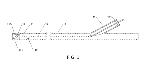
are in
2
CA 03180710 2022- 11- 29
communication with the bypass pipe to be used as the effective air outlets for
gas
venting.
[0015] Optionally, the sealing member has an outer diameter
equal to the inner
diameter of the regulating chamber, at least two rows of small air outlets are
provided,
each row of small air outlets includes at least one small air outlet, and at
least two groups
of small air outlets are distributed in an axial direction of the mandrel;
[0016] where when the sealing member is at the large air outlet of the
mandrel, each
of the small air outlets is in communication with the bypass pipe to be used
as the
effective air outlet; and when the sealing member moves to the second end
portion of
the mandrel under an action of the traction member, a quantity of small air
outlets that
are in communication with the bypass pipe to be used as the effective air
outlets is
reduced.
[0017] Optionally, the sealing assembly further includes a
sealing ring pressing
member, the sealing ring pressing member is sleeved at the tail end of the
bypass pipe,
the sealing ring is clamped between the sealing ring pressing member and the
tail end
of the bypass pipe in a length direction of the bypass pipe, and the sealing
ring pressing
member is provided with a through hole for the traction member to pass
through.
[0018] According to a second aspect of the present invention, a
flexible cryoprobe
with an adjustable flow is provided, and includes the flow regulating assembly
according to each of the foregoing embodiments, where the flexible cryoprobe
further
includes: a needle catheter component, a handle component, and an extension
tube
component, where the extension tube component includes an air inlet tube, an
air return
tube, and a regulating tube;
[0019] the flow regulating assembly is arranged inside the
needle catheter
component, and the needle catheter component is connected to the handle
component;
[0020] the air inlet tube is connected to the bypass pipe in
the flow regulating
assembly, and a gas in the regulating chamber is discharged through the air
return tube;
and
[0021] the regulating tube is configured to directly or
indirectly adjust an axial
position of the sealing member in the regulating chamber.
[0022] Optionally, the needle catheter component includes a
needle tip, a needle, an
inner tube assembly, and an outer tube assembly; and
3
CA 03180710 2022- 11- 29
[0023] the needle includes a needle front section and a needle
rear section, the needle
tip is arranged on a front end portion of the needle, and the needle rear
section is fixedly
connected to the inner tube assembly and the outer tube assembly.
[0024] Optionally, a thermal insulation layer is arranged
between the inner tube
assembly and the outer tube assembly, and the thermal insulation layer is a
thermal
insulation material or a vacuum layer.
[0025] Optionally, the regulating chamber is arranged inside
the needle front section,
the J-T slot is provided inside the inner tube assembly, and a gas in the
needle returns
through a gap between the inner tube assembly and the J-T slot.
[0026] Optionally, the handle component is provided with a toggle rod and a
connecting member, one end of the connecting member is connected to the
traction
member, the other end of the connecting member is connected to the toggle rod,
and
the axial position of the sealing member in the regulating chamber is adjusted
by the
toggle rod.
[0027] In the flow regulating assembly according to the present invention,
the
mandrel is provided with the large air outlet and the small air outlet, the
sealing member
is arranged in the regulating chamber, and the sealing member and the traction
member
penetrate through the bypass pipe to be connected to the outside, and the
sealing
member is driven by the traction member to change the quantity of the
effective air
outlets by changing the position of the sealing member, thus achieving a multi-
gear
flow regulation function.
BRIEF DESCRIPTION OF DRAWINGS
[0028] To describe technical solutions in embodiments of the
present invention or
in the prior art more clearly, accompanying drawings required in the
description of the
embodiments or the prior art are briefly described below. Obviously, the
accompanying
drawings in the following description illustrate only some of the embodiments
of the
present invention, and a person of ordinary skill in the art can further
obtain other
accompanying drawings based on these accompanying drawings without creative
efforts.
[0029] FIG. 1 is a schematic structural diagram of a flow regulating
assembly during
axial sealing in an embodiment of the present invention;
[0030] FIG. 2 is a schematic structural diagram of a flow
regulating assembly during
radial sealing in an embodiment of the present invention;
4
CA 03180710 2022- 11- 29
[0031] FIG. 3 is a schematic structural diagram of a flow
regulating assembly in a
high flow state in an embodiment of the present invention;
[0032] FIG. 4 is a schematic structural diagram of a flow
regulating assembly in a
low flow state in an embodiment of the present invention;
[0033] FIG. 5 is a schematic structural diagram of a flexible cryoprobe
with an
adjustable flow in an embodiment of the present invention;
[0034] FIG. 6 is a schematic structural diagram of a needle
part of a flexible
cryoprobe with an adjustable flow in a cryoablation mode in an embodiment of
the
present invention;
[0035] FIG. 7 is a schematic structural diagram of a handle front section
of a flexible
cryoprobe with an adjustable flow in an embodiment of the present invention;
[0036] FIG. 8 is a schematic structural diagram of a handle
rear section of a flexible
cryoprobe with an adjustable flow in an embodiment of the present invention;
[0037] FIG. 9 is a schematic structural diagram of a needle
part of a flexible
cryoprobe with an adjustable flow in a cryoadhesion mode in an embodiment of
the
present invention; and
[0038] FIG. 10 is a schematic structural diagram of a handle
rear section of a flexible
cryoprobe with an adjustable flow in an embodiment of the present invention.
[0039] Description of reference numerals:
[0040] 1 - Flow regulating assembly;
[0041] 11 - Regulating chamber;
[0042] 111 -Large air outlet;
[0043] 112 - Small air outlet;
[0044] 113 - Sealing surface;
[0045] 12 - Sea I i ng member;
[0046] 121 - Sealing ball;
[0047] 13 - J-T slot;
[0048] 14 - Bypass pipe;
[0049] 141 - Sealing ring;
[0050] 142 - Sealing ring pressing member;
[0051] 15 - Thin drawn wire;
[0052] 16 - Thick drawn wire;
[0053] 2 - Needle catheter component;
[0054] 21 - Needle tip;
5
CA 03180710 2022- 11- 29
[0055] 22 - Needle;
[0056] 221 - Needle front section;
[0057] 222 - Needle rear section;
[0058] 23 - Inner tube assembly;
[0059] 231 - Inner flexible catheter;
[0060] 232 - Squeezing tube;
[0061] 233 - Air return connecting tube;
[0062] 24 - Outer tube assembly;
[0063] 241 - Outer flexible catheter;
[0064] 242 - Quick tightening nut;
[0065] 243 - Vacuum chamber;
[0066] 244 - Pagoda joint;
[0067] 3 - Handle component;
[0068] 31 - Front handle;
[0069] 311 - Sliding groove;
[0070] 312 - Limiting hole;
[0071] 32 - Rear handle;
[0072] 33 - Protective elbow;
[0073] 34 - Button assembly;
[0074] 341 - Button box;
[0075] 342 - Sliding block;
[0076] 3421 -Toggle groove;
[0077] 3422 - Clamping rod hole;
[0078] 343 - Button;
[0079] 344 - Connecting rod;
[0080] 345 - Spring;
[0081] 346 - Toggle switch;
[0082] 347 - Switch wire;
[0083] 4 - Extension tube component;
[0084] 41 - Extension tube;
[0085] 42. Air inlet tube;
[0086] 43 - Air return tube;
[0087] 44 - Shunt tube;
[0088] 441 - Leading-out hole;
6
CA 03180710 2022- 11- 29
[0089] 45 - Vacuum hose.
DESCRIPTION OF EMBODIMENTS
[0090] The technical solutions of the embodiments of the
present invention are
clearly and completely described below with reference to the accompanying
drawings
in the embodiments of the present invention. Apparently, the described
embodiments
are merely some rather than all of the embodiments of the present invention.
All other
embodiments obtained by a person of ordinary skill in the art based on the
embodiments
of the present invention without creative efforts shall fall within the
protection scope of
the present invention.
[0091] The terms "first", "second", "third", "fourth", etc. (if any) in the
description,
claims, and the foregoing accompanying drawings of the present invention are
used to
distinguish between similar objects and are not necessarily used to describe a
specific
order or sequence. It should be understood that data used in such a way may be
interchanged under appropriate circumstances so that the embodiments of the
present
invention described herein can be implemented in an order other than those
illustrated
or described herein. In addition, the terms "including" and "having", and any
variations
thereof, are intended to cover non-exclusive inclusion, for example, a
process, method,
system, product, or device including a series of steps or units is not
necessarily limited
to those steps or units explicitly listed, but may include other steps or
units not explicitly
listed or inherent to these processes, methods, products, or devices.
[0092] The technical solution of the present invention is
described in detail below
with reference to specific embodiments. The following several specific
embodiments
can be combined with each other, and the same or similar concepts or processes
may
not be described in detail again in some embodiments.
[0093] An existing cryoadhesion technology is generally only used for
cryobiopsy,
cryotomy and foreign body extraction in a natural orifice, but its temperature
is not low
enough and ice balls are small. Thus, the existing cryoadhesion technology
cannot
effectively implement ablation therapy. If an ablation gas such as nitrogen or
argon is
introduced to an existing cryoadhesion product, a lower temperature and a
larger
freezing range cannot be achieved due to a flow limitation of the product
itself. An
existing cryoablation product can also achieve cryoadhesion by certain means,
such as
directly introducing carbon dioxide or nitrous oxide, but this method wastes a
large
amount of gas, and most of cold energy in return air is directly drained,
resulting in a
7
CA 03180710 2022- 11- 29
large amount of liquid or solid carbon dioxide or nitrous oxide being sprayed
from or
accumulated at an exhaust port. In addition, if this method is applied to a
cryoablation
product passing through a natural orifice, a large amount of surplus cold
energy of the
return air leads to hardening of a flexible catheter section. Thus, a needle
sticking to a
tissue cannot be taken out from the curved orifice or endoscope forceps
channel
smoothly.
[0094] The present invention provides a flow regulating
assembly, which includes a
mandrel, where the mandrel internally has a hollow structure, and the hollow
structure
is a regulating chamber for communicating with a gas.
[0095] A first end portion of the mandrel is provided with a large air
outlet, a side
wall of the mandrel is provided with a small air outlet, and the large air
outlet has an
inner diameter less than that of the regulating chamber.
[0096] The large air outlet and the small air outlet may be
understood in such a way
that the large air outlet has a pore diameter greater than that of the small
air outlet, rather
than mean holes of a certain size. Therefore, as long as the large air outlet
has a pore
diameter greater than that of the small air outlet, pore diameters of any
value do not
deviate from the foregoing description.
[0097] For example, the mandrel has a tubular structure with a uniform inner
diameter. The first end portion of the mandrel is provided with an annular
structure with
a middle through hole, and when the annular structure is fixedly arranged on
the first
end portion of the mandrel, a large air outlet with an inner diameter less
than that of the
mandrel is formed.
[0098] The small air outlet is provided in the side wall of the
mandrel. One or more
small air outlets may be provided. When a plurality of small air outlets are
provided,
the plurality of small air outlets are provided in different axial positions.
At the same
axial position, different small air outlets may be provided in different
radial positions.
In addition, the small air outlets may have the same pore diameter and size,
or have
different pore diameters and sizes in implementations.
[0099] A second end portion of the mandrel is connected to a front end of a J-
T slot,
and a rear end of the J-T slot is connected to a bypass pipe. For example, the
J-T slot is
a flexible hose, and may be a flexible tube made of metal or another low-
temperature-
resistant material. The large air outlet and the small air outlet are located
on a same side
of the bypass pipe in an axial direction of the mandrel.
8
CA 03180710 2022- 11- 29
[0100] A sealing member is arranged in the regulating chamber,
and the sealing
member has an outer diameter less than or equal to an inner diameter of the
regulating chamber and greater than an inner diameter of the large air outlet.
The
sealing member can axially move in the regulating chamber, and a quantity of
effective air outlets in the large air outlet and the small air outlet is
changed by
adjusting a position of the sealing member. The effective air outlet is an air
outlet
which is not blocked by a sealing member and can allow a gas to pass through.
[0101] The sealing member is connected to one end of a traction
member, and
the other end of the traction member is led out through the bypass pipe. The
traction member is configured to pull the sealing member to move in the axial
direction of the mandrel to adjust the position of the sealing member. For
example,
the bypass pipe may be a three-way pipe structure directly arranged on the
side
wall of the mandrel and formed with two ends of the mandrel, and the traction
member is connected to the sealing member in the mandrel through the bypass
pipe; or the bypass pipe is a leading-out structure from the regulating
chamber
through another pipeline, and is connected to the sealing member in the
regulating
chamber through the pipeline.
[0102] The sealing member axially moves in the regulating
chamber under an
action of the traction member, and a quantity of effective air outlets is
changed by
adjusting the position of the sealing member.
[0103] In summary, in the flow regulating assembly according to
the present
invention, the mandrel is provided with the large air outlet and the small air
outlet,
the sealing member is arranged in the regulating chamber, and the sealing
member
and the traction member penetrate through the bypass pipe to be connected to
the
outside, and the sealing member is driven by the traction member to change the
quantity of the effective air outlets by changing the position of the sealing
member,
thus achieving a multi-gear flow regulation function.
[0104] FIG. 1 is a schematic structural diagram of a flow
regulating assembly
during axial sealing in an embodiment of the present invention; and FIG. 2 is
a
schematic structural diagram of a flow regulating assembly during radial
sealing
in an embodiment of the present invention. With reference to FIG. 1, a flow
regulating assembly 1 includes at least a regulating chamber 11, a sealing
member
12, a J -T slot 13, a bypass pipe 14, and a thin drawn wire 15.
9
CA 03180710 2022- 11- 29
[0105] The sealing member 12 has an outer diameter less than an
inner diameter
of the regulating chamber 11 and greater than an inner diameter of a large air
outlet
111. When the sealing member 12 is positioned on a first end portion of a
mandrel,
because the sealing member 12 has an outer diameter greater than the inner
diameter of the large air outlet 111, the large air outlet 111 is sealed by
the sealing
member 12. As a result, a gas in the regulating chamber 11 cannot be
discharged
through the large air outlet 111, but can only be discharged through a small
air
outlet 112 provided in a side wall of the mandrel, that is, in this case, the
large air
outlet is closed, and the small air outlet is in communication with the bypass
pipe,
to be used as the effective air outlet for gas venting. Optionally, the
sealing
member 12 may have a spherical structure or another shape that can block the
large
air outlet 111. No matter what shape is provided, the shape does not depart
from
the scope of this embodiment.
[0106] When an external force acts on a traction member to pull
the sealing
member 12, the sealing member 12 moves away from the large air outlet 111
under
traction of the traction member. Because the sealing member 12 has an outer
diameter less than the inner diameter of the regulating chamber 11, after the
sealing member 12 leaves the large air outlet 111, the gas passes through a
gap
between the sealing member 12 and the mandrel, so that the gas in the
regulating
chamber 11 can be discharged simultaneously from the large air outlet 111 and
the
small air outlet 112. In this case, the large air outlet 111 and the small air
outlet
112 are both in communication with the bypass pipe to be used as the effective
air
outlet for gas venting, and the flow regulating assembly reaches a maximum gas
venting quantity and is in a high flow mode.
[0107] When the external force disappears and the sealing member 12 moves
forward to the end under the action of the inlet air flow, the sealing member
12
blocks the large air outlet 111 to form axial seal, and the gas in the entire
flow
regulating assembly 1 is discharged through only the small air outlet 112. In
this
case, the flow regulating assembly 1 is in a low flow mode in which the gas
flow
is less than that of the high flow mode.
[0108] With reference to FIG. 2, at least two rows of small air
outlets are
provided, each row of small air outlets includes at least one small air
outlet, and
different groups of small air outlets 112 are provided in different axial
positions
in the side wall of the mandrel. That is, at least two groups of small air
outlets are
CA 03180710 2022- 11- 29
distributed in an axial direction of the mandrel; the sealing member 12 has an
outer
diameter equal to an inner diameter of the regulating chamber 11 and greater
than
an inner diameter of a large air outlet 111. When the sealing member 12 is
positioned on a first end portion of the mandrel, because the sealing member
12
has an outer diameter greater than the inner diameter of the large air outlet
111,
the large air outlet 111 is sealed by the sealing member 12. As a result, a
gas in
the regulating chamber 11 cannot be discharged through the large air outlet
111,
but can only be discharged through a small air outlet provided in the side
wall of
the mandrel. In this case, each of the small air outlets is in communication
with
the bypass pipe, to be used as the effective air outlet.
[0109] When the external force acts on the traction member to
pull the sealing
member 12, the sealing member 12 is pulled away from the large air outlet 111
by
the traction member. Because the sealing member 12 has an outer diameter equal
to the inner diameter of the mandrel, after the sealing member 12 leaves the
large
air outlet 111, the gas cannot be discharged through the large air outlet 111,
but
can only be discharged through the small air outlets 112. As the sealing
member
12 continues to move in the axial direction, the sealing member 12
sequentially
blocks a plurality of small air outlets 112, thus achieving an effect of
changing the
flow. This may also be understood as that the quantity of small air outlets
that are
in communication with the bypass pipe to be used as the effective air outlets
is
reduced.
[0110] Specifically, when the blocked small air outlets 112 are
different,
corresponding small air outlets that cannot vent the gas introduced through
the
bypass pipe include the small air outlets 112 directly blocked by the sealing
member and small air outlets 112 in front thereof. Furthermore, the small air
outlets 112 (i.e., effective air outlets) that can vent the gas introduced
through the
bypass pipe are small air outlets located behind the sealing member 12 at
present.
The change in the quantity of these small air outlets can achieve the effect
of
changing the flow.
[0111] When the external force disappears and the sealing member 12 moves
forward to the end under the action of the inlet air flow, the sealing member
12
blocks the large air outlet 111 to implement axial seal, and all the small air
outlets
112 in the entire flow regulating assembly 1 can be used to vent the gas,
thereby
implementing the high flow mode. For example, a plurality of small air outlets
112
11
CA 03180710 2022- 11- 29
are provided in the same axial position, thereby ensuring the gas venting
quantity
of the small air outlets 112.
[0112] Optionally, the sealing member 12 is made of metal, and
airtightness
between assemblies is ensured through precision machining. Alternatively, a
surface of the sealing member 12 is made of a material with a certain elastic
deformation capacity to ensure the sealing effect, such as a low-temperature-
resistant rubber material, which can effectively reduce precision requirement
of a
machining and production process.
[0113] To ensure the sealing effect, a sealing surface 113 is
provided at the large
air outlet 111, and the sealing surface 113 is a contact surface matching the
shape
of the sealing member 12. Alternatively, a sealing ring made of a low-
temperature-
resistant rubber material is arranged at the large air outlet 111 to ensure an
airtight
effect between the large air outlet 111 and the sealing member 12.
[0114] A sealing assembly is arranged between the traction
member and the
bypass pipe 14 to ensure an airtight effect on the regulating chamber 11. The
sealing assembly includes a sealing ring 141 and a sealing ring pressing
member
142, which are configured to dynamically seal a gap between the bypass pipe 14
and a thick drawn wire to prevent air leakage. The sealing ring pressing
member
142 and the bypass pipe 14 may be connected to each other by using threads.
[0115] In summary, in the foregoing implementation, the sealing member is
connected to the traction member, the traction member makes the sealing member
communicate with the outside by using the bypass pipe, and the sealing member
axially moves under the driving of the traction member. When the sealing
member
is at a different position, the quantity of effective air outlets changes, so
that the
gas venting quantity of the mandrel is adjusted, thereby achieving a function
of
flow regulation.
[0116] FIG. 3 is a schematic structural diagram of a flow
regulating assembly
in a high flow state in an embodiment of the present invention; and FIG. 4 is
a
schematic structural diagram of a flow regulating assembly in a low flow state
in
an embodiment of the present invention. A flow regulating assembly 1 includes
a
regulating chamber 11, a sealing member 12 (such as a sealing ball 121), a j -
T slot
13, a bypass pipe 14, and a traction member.
[0117] In a possible implementation, the traction member may be
a thin traction
wire, or may be two or more sections of traction wires connected to each
other.
12
CA 03180710 2022- 11- 29
When the traction member is two or more sections of traction wires connected
to
each other, the traction member includes a thin drawn wire 15 connected to the
sealing member 12 to reduce an impact of the thin drawn wire on an internal
air
pressure. The section led out from the bypass pipe 14 is a thick drawn wire
16, and
the thick drawn wire 16 has a diameter greater than that of the thin drawn
wire 15,
which facilitates operations on the thin drawn wire such as fixing and force
application, increases the strength, and reduces a risk of failure.
[0118] The regulating chamber 11 is provided with a large air
outlet 111 located
at the front end, small air outlets 112 located in the side wall, and a
sealing surface
113 located behind the large air outlet 111, where at least two symmetrical
small
air outlets 112 are provided, and the bypass pipe 14 is provided with a
sealing ring
141 and a sealing ring pressing member 142. The front and rear of the J -T
slot 13
are fixedly sealed with a rear end of the regulating chamber 11 and a front
end of
the bypass pipe 14 respectively. The thin drawn wire 15 is fixedly connected
to
the sealing ball 121 and the thick drawn wire 16. The sealing ball 121 is
located
inside the regulating chamber 11, and the sealing ball 121 has a diameter less
than
the inner diameter of the regulating chamber 11, so that the sealing ball 121
can
move back and forth in the regulating chamber 11, and a gap between the
sealing
ball and the regulating chamber does not affect the overall flow of inlet air.
[0119] In a possible implementation, the thin drawn wire 15 is located
inside
the J-T slot 13; the thin drawn wire 15 has a diameter less than the inner
diameter
of the J-T slot 13; and the thin drawn wire 15 can move back and forth in the
J -T
slot without hindering the air flow from passing through. The thick drawn wire
16
is located inside a branch of the bypass pipe 14.
[0120] During normal operation, the gas enters from a rear end of the
bypass
pipe 14, is conveyed to the inside of the regulating chamber 11 through the
inside
of the J-T slot 13, and is finally discharged through the air outlet of the
regulating
chamber 11. When the thick drawn wire 16 is pulled backward, the thin drawn
wire 15 finally drives the sealing ball 121 to move backward. In this case,
both the
large air outlet 111 and the small air outlet 112 of the regulating chamber
are used
for gas venting, and the corresponding flow is maximum. In this case, a
cryoablation mode can be implemented by introducing nitrogen or argon. When
the thick drawn wire 16 is pushed forward, a pulling force on the thin drawn
wire
15 disappears, and the sealing ball 121 moves forward under the action of the
inlet
13
CA 03180710 2022- 11- 29
air flow, and finally abuts against the sealing surface 113 to block the large
air
outlet 111. In this case, only the small air outlet 112 is used for gas
venting, and
the corresponding flow is minimum. In this case, a cryoadhesion mode can be
implemented by introducing carbon dioxide or nitrous oxide.
[0121] Since the gas flow regulation method and process are the same as
those
of the examples in FIG. 1 and FIG. 2, details are not described in this
embodiment
again.
[0122] In summary, in this embodiment, through the arrangement
of the traction
member connected to the sealing member, the axial position of the sealing
member
is manually adjusted through external force application, so that a user can
freely
adjust a flow size, thereby effectively improving ease of use.
[0123] The present application further provides a flexible
cryoprobe with an
adjustable flow. FIG. 5 is a schematic structural diagram of a flexible
cryoprobe
with an adjustable flow in a low flow state in an embodiment of the present
invention. The flexible cryoprobe with an adjustable flow according to the
present
application includes the flow regulating assembly 1 according to the foregoing
embodiments of FIG. 1 to FIG. 4, a needle catheter component 2, a handle
component 3, and an extension tube component 4, where the handle component 3
includes a front handle 31, a rear handle 32, a protective elbow 33, and a
button
assembly 34. The button assembly 34 is configured to switch between the low
flow
mode and the high flow mode. The extension tube component 4 includes an
extension tube 41, an air inlet tube 42, an air return tube 43, a shunt tube
44, and
a vacuum hose 45. The entire flow regulating assembly 1 is arranged inside the
needle catheter component 2 and the shunt tube 44. The protective elbow 33 is
arranged on a front section of the handle component 3, and is configured to
protect
a flexible pipeline at a front end of the flexible cryoprobe. A gas in a
regulating
chamber is discharged through the air return tube. A regulating tube is
configured
to directly or indirectly regulate and control the axial position of the
sealing
member in the regulating chamber, and for example, may be connected to the
traction member in the flow regulating assembly.
[0124] In summary, in the flexible cryoprobe with an adjustable
flow according
to the present application, the flow regulating assembly with an adjustable
flow is
arranged in a needle rod, and the gas flow inside the needle rod is manually
controlled by using the traction member. The gas flow is regulated in the
needle
14
CA 03180710 2022- 11- 29
rod, and the temperature at the needle rod is manually controlled, which
solves the
problems of unstable flow, a severe loss of cold energy, an excessively-narrow
adjustable range of an operating pressure, and a corresponding excessively-
narrow
adjustable flow range which easily occur inside a host in related
technologies.
[0125] Since in the present invention, the flow regulating assembly is
placed in
an effective treatment area (needle) at the most remote end, the user does not
need
to worry about the loss of cold energy during flow regulation, and it can be
ensured
that the flow regulation can be implemented when the air inlet pressure of the
air
outlet is almost unchanged. The flow regulation can be fed back to a heat
absorption amount of a lesion tissue almost without delay, so that the
cryoprobe
with an adjustable flow according to the present invention can be used in the
high-
pressure field. An existing technology of using a flow controller for flow
regulation is relatively stable, but the flow controller can only be placed in
the
host far away from the effective treatment area (needle). Thus, a change of
cold
energy at the needle lags behind the flow regulation. In addition, there are
few
flow controllers that can implement stable flow control under high pressure,
and
when a required flow is relatively low, a very small flow cross section
appears at
the flow controller. In this way, a relatively low temperature is generated
inside
the flow controller, which causes the loss of cold energy and cannot implement
effective cooling of the needle, thus making the existing flow controller
generally
unsuitable for a state of a high-pressure gaseous flow.
[0126] FIG. 6 is a schematic structural diagram of a needle
part of a flexible
cryoprobe with an adjustable flow in a cryoablation mode in an embodiment of
the
present invention. With reference to FIG. 6, the needle catheter component 2
includes a needle tip 21, a needle 22, an inner tube assembly 23, and an outer
tube
assembly 24. The needle 22 includes a needle front section 221 and a needle
rear
section 222, where the needle front section 221 is fixedly sealed with the
needle
tip 21, the needle rear section 222 is fixedly connected to the inner tube
assembly
23 and the outer tube assembly 24. A certain gap is provided between the inner
tube assembly 23 and the outer tube assembly 24, and the gap is filled with a
thermal insulation material or vacuumized to implement vacuum insulation of
the
flexible catheter section and prevent frostbite of a normal orifice.
[0127] In summary, since the certain gap is provided between
the inner tube
assembly and the outer tube assembly, a thermal insulation layer is arranged
in the
CA 03180710 2022- 11- 29
gap, which ensures that internal cold air cannot be guided to the outside to
cause
frostbite of the normal orifice, and ensures that external heat cannot be
introduced
into the assembly, thus ensuring the freezing effect.
[0128] FIG. 7 is a schematic structural diagram of a handle
front section of a
flexible cryoprobe with an adjustable flow in an embodiment of the present
invention. Referring to FIG. 7, the inner tube assembly 23 includes an inner
flexible catheter 231, a squeezing tube 232, and an air return connecting tube
233,
where a front end of the air return connecting tube 233 is inserted into a
rear end
of the inner flexible catheter 231, and the squeezing tube 232 is sleeved at
the rear
end of the inner flexible catheter 231 and ensures connection strength and
sealing
in a squeezing mode.
[0129] The outer tube assembly 24 includes an outer flexible
catheter 241, a
quick tightening nut 242, a vacuum chamber 243, and a pagoda joint 244. A rear
end of the outer flexible catheter 241 is flared and then sleeved on a front-
end
tapered surface of the vacuum chamber 243. The quick tightening nut 242
squeezes
the outer flexible catheter 241 on the front-end tapered surface of the vacuum
chamber 243, thereby ensuring connection strength and sealing.
[0130] The pagoda joint 244 is located on a branch of the
vacuum chamber 243
and is in communication with the inside of the vacuum chamber 243. The outer
tube assembly 24 is sleeved on the inner tube assembly 23, a rear end of the
vacuum chamber 243 is fixedly sealed with an outer surface of the squeezing
tube
232, and the vacuum hose 45 is sleeved on the pagoda joint 244. A vacuum pump
inside the host can vacuumize the gap between the outer tube assembly 24 and
the
inner tube assembly 23 through the vacuum hose 45.
[0131] For example, the shunt tube 44 further includes a leading-out hole
441,
and the leading-out hole 441 is used to lead out the branch of the bypass pipe
14
and fixedly seal the bypass pipe. The rear end of the bypass pipe 14 is
inserted
into the air inlet tube and fixedly sealed, and the air inlet tube 42 and the
air return
tube 43 are both inserted into the rear end of the shunt tube 44 and fixedly
sealed.
[0132] Referring to FIG. 8, the front handle 31 includes a sliding groove
311
and two limiting holes 312, the first limiting hole 312 in front corresponds
to the
cryoadhesion mode, and the second limiting hole 312 corresponds to the
cryoablation mode. The button assembly 14 includes a button box 341, a sliding
block 342, a button 343, a connecting rod 344, a spring 345, a toggle switch
346,
16
CA 03180710 2022- 11- 29
and switch wires 347, where the sliding block 342 and the toggle switch 346
are
placed in the button box 341, the button box 341 is fixed to an inner surface
of the
front handle 31, the sliding block 342 can slide back and forth in the button
box
341, and the toggle switch 346 is fixed in the button box 341. A rear end of
the
sliding block 342 further includes a toggle groove 3421 and a connecting rod
hole
3422. The toggle groove 3421 is used for the sliding block 342 to toggle the
toggle
switch 346 back and forth during sliding. A rear end of the thick drawn wire
16
passes through the button box 341 and is fixedly connected to a front end of
the
sliding block 342. The spring 345 and the connecting rod 344 are placed in the
connecting rod hole 3422 of the sliding block 342. The connecting rod 344 is
divided into four sections. The first section (the uppermost section in the
figure)
is used to connect to the button 343 and slide back and forth in the sliding
groove
311, the second section is used to be inserted into the limiting hole 312 to
fix the
position of the button 343, the third section is used to clamp an upper limit
position
of the connecting rod 344 to prevent the connecting rod 344 from being pushed
out by the spring 345, and the fourth section is used to be sleeved with the
spring
345. The toggle switch is connected to three switch wires 347, and the switch
wires
347 are connected to an internal circuit of the host and configured to open
different
gas pipelines in different modes.
[0133] The present application is further explained in detail below with
reference to a usage process.
[0134] Referring to FIG. 6 and FIG. 8, in the cryoablation
mode, the button 343
is toggled backward, the second section of the connecting rod 344 is clamped
in
the second limiting hole 312, the connecting rod 344 drives the sliding block
342
to move backward, and the sliding block 342 drives the sealing ball 121, by
using
the thick drawn wire 16 and the thin drawn wire 15, to move backward, thus
opening the large air outlet 111. In addition, the toggle groove 3421 toggles
the
toggle switch 346 backward, and the switch wire 347 leads an electrical signal
into
the internal circuit of the host. The host first starts exhaust of all
pipelines once to
exhaust the original remaining gas, and then opens a cryoablation pipeline
connected to nitrogen or argon. The nitrogen or argon is introduced into the
flexible cryoprobe, passes through the air inlet tube 42, the bypass pipe 14,
the J -
T slot 13, and the regulating chamber 11, and is finally sprayed out to the
needle
front section 221 through the large air outlet 111 and the small air outlet
112 to
17
CA 03180710 2022- 11- 29
complete throttling refrigeration, and absorbs a large amount of heat from a
lesion
tissue outside the needle 22 to form ice balls for ablation therapy. The
nitrogen or
argon that has absorbed heat is discharged out of the needle through the
needle
rear section 222, the inner flexible catheter 231, the air return connecting
tube 233,
the shunt tube 44, and the air return tube 43.
[0135] Referring to FIG. 9 and FIG. 10, when it is required to
start the
cryoadhesion mode, the button 343 is pressed to move the second section of the
connecting rod 344 out of the second limiting hole 312. In this case, the
spring
345 is compressed, and the first section of the connecting rod 344 enters the
sliding
groove 311, and pushes the button 343 forward. The connecting rod 344 drives
the
sliding block 342 to move forward, and the sliding block 342 drives the thick
drawn wire 16 to be pushed into the bypass pipe 14. In this case, due to the
existence of air flow in an air inlet pipeline, the sealing ball 121 is pushed
forward
by the air flow to abut against the sealing surface 113, thus blocking the
large air
outlet 111. After the button 343 is pushed to the bottom, the button 343 is
released,
and the connecting rod 344 is pushed out upward by the spring 345 until the
second
section thereof is clamped in the first limiting hole 312. In this case, the
toggle
groove 3421 toggles the toggle switch 346 forward, and the switch wire 347
leads
the electrical signal into the internal circuit of the host. The host first
starts exhaust
of all pipelines once to exhaust the original remaining gas, and then opens a
cryoadhesion pipeline connected to carbon dioxide or nitrous oxide, to
introduce
the carbon dioxide or nitrous oxide into the flexible cryoprobe. Finally, the
carbon
dioxide or nitrous oxide is sprayed out into the needle front section 221
through
only the small air outlet 112, to implement cryoadhesion with a tissue outside
the
needle 22. Because the flow of the small air outlet 112 is relatively small,
cold
energy generated by throttling is almost completely absorbed by the tissue at
the
needle 22, so that the cold energy of the return gas is very small, avoiding
hardening of the flexible catheter caused by an excessively low temperature.
[0136] Finally, it should be noted that the foregoing
embodiments are used only
to describe the technical solutions of the present invention, and are not
intended
to limit the present invention. Although the present invention is described in
detail
with reference to the foregoing embodiments, a person of ordinary skill in the
art
should understand that he/she can still modify the technical solutions
described in
each foregoing embodiment, or perform equivalent replacements on some or all
of
18
CA 03180710 2022- 11- 29
the technical features therein. Such modifications or replacements do not make
the
essence of the corresponding technical solution depart from the scope of the
technical solution of each embodiment of the present invention.
19
CA 03180710 2022- 11- 29