Note: Descriptions are shown in the official language in which they were submitted.
CA 03180844 2022-10-20
WO 2021/214777
PCT/IL2021/050465
ABUTMENT FOR IMPLANT CONNECTOR
CROSS-REFERENCE TO RELA _______________ ILD APPLICATION
[0001] This application claims the benefit of provisional patent applications
No.
63/013,564 filed April 22nd, 2020, titled " Uni-Base and Clicq-Base - Titanium
Base
for Screw Retained Crowns and Bridges", and No. 63/039,003 filed June 15th,
2020,
titled "Clicq-Base - Titanium Base for Screw Retained Crowns and Bridges with
an
extra adapter for bar system Clicq Multi Base on X", which are hereby
incorporated
by reference in their entireties without giving rise to disavowment.
TECHNICAL FIELD
[0002] The present disclosure relates to the field of dental abutments in
general, and
to inclined dental abutments, in particular.
BACKGROUND
[0003] Dental abutments are commonly connected to the dental implant by a
screw
inserted from the top of the abutment and emerging from its base for screwing.
Such
connection method determines a maximal angle which a screw inserted through
the
abutment may form with respect to the longitudinal axis of the abutment. In
known
plain abutments, the maximal angle (which may be referred to also as a
threshold
angle) is about 9 degrees. Larger angle may place in risk the integrity of the
abutment
walls due to insufficient width in portions thereof, resulting from the
inclination of the
screw channel to the walls.
[0004] Plain dental base abutments thus have an inclination of up to 10
degrees.
Inclinations of more than 10 degrees, typically do not allow to prepare an
appropriate
screw channel in the abutment in line with the implant axis, as required for
inserting a
screw through the abutment for securing it to the implant.
1
CA 03180844 2022-10-20
WO 2021/214777 PCT/IL2021/050465
BRIEF SUMMARY
[0005] One broad aspect of the disclosed subject matter is the provision of
dental
abutments inclined up to 30 degrees and yet need not have more than a single
screw
channel nor a conical adaptor, for securing the abutment to a dental implant
by a
screw.
[0006] Another broad aspect of the disclosed subject matter is the provision
of
tolerated connective complex for tethering a milled bar to a plurality (e.g.
four) dental
implants.
[0007] In the context of this specification the term 'distal end' refers to an
end of a
described part, which in vivo (i.e., in the mouth of a patient undergoing a
dental
procedure by a dentist), is remoter from the approach of the dentist relative
to an
opposite end of that part, and which may thus be referred to as the 'proximal
end' of
the part described.
[0008] A first exemplary embodiment of the disclosed subject matter is a
dental
abutment, comprising first and second units, the first unit is removably
connectible to
an unclaimed in vivo dental implant by any acceptable connective element
pivotable
with respect to both units, said first unit having a distal end contoured in
match with
an end contour of the dental implant, and a proximal end contoured in match
with a
distal end contour of the second unit, said proximal end comprises a
supportive
surface adapted to lie in contact with a contact surface located on the distal
end of the
second unit, wherein a longitudinal axis of the second unit is perpendicular
to a plane
tangential to the distal end of the second unit, wherein a longitudinal axis
of the
second unit forms a predetermined angle with respect to a longitudinal axis of
the first
unit such that an angle between the longitudinal axis of the second unit and a
longitudinal axis of a dental implant of interest when the first and second
units are
connected together and to the dental implant of interest, is equal to the
predetermined
angle, wherein the first and second units are connectible together by
connective
means other than and unattached to the connective element.
[0009] The dental abutment may further comprise mutual rotation preventive
preparation structure configured to allow a dentist to disable in vivo
pivoting of the
second unit with respect to the first.
2
CA 03180844 2022-10-20
WO 2021/214777 PCT/IL2021/050465
[0010] In various embodiments of the presently disclosed subject matter, the
mutual
rotation preventive preparation structure comprises matching rotational
symmetry
breaking male-female contours (e.g. one or more pairs each pair comprises
matching
protrusion and indentation notches), wherein at least one rotational symmetry
breaking male contour is formed in one of the first and the second units,
wherein at
least one rotational symmetry breaking female contour in match with the at
least one
rotational symmetry breaking male contour is formed in another of the first
and the
second units.
[0011] In various embodiments of the presently disclosed subject matter, the
mutual
rotation preventive preparation comprises outwardly facing wall surface
extending
from a mid-portion of the first unit towards the proximal end of the first
unit and
facing away from the longitudinal axis of the second unit once the second unit
is
connected to the first, wherein the second unit is contoured and dimensioned
to
unhide the outwardly facing wall surface, whereby allowing a dental prosthesis
to be
integrated in a first portion thereof with the outwardly facing wall surface
and in a
second portion thereof with an outwardly facing wall surface of the second
unit.
[0012] In various embodiments of the presently disclosed subject matter, the
supportive surface is on a plane tilted with respect to a longitudinal axis of
the first
unit, by a degree of tilting resulting in that the predetermined angle is
between 11 and
30 degrees.
[0013] In various embodiments of the presently disclosed subject matter, the
outer
walls of the second unit are configured to extend without intersecting the
longitudinal
axis of the first unit and are free of through holes associated with screw
channel.
[0014] In various embodiments of the presently disclosed subject matter, the
second
unit is permanently connectible to the first unit by welding, soldering,
sticking, or
gluing.
[0015] In various embodiments of the presently disclosed subject matter, the
second
unit comprises a through hollow extending between an opening at the proximal
end of
the second unit and between a proximal end of the connective element (or a
continuum hollow formed in the proximal end of the first unit, in which the
end of the
connective element is located) , whereby providing a dentist with an access to
a
3
CA 03180844 2022-10-20
WO 2021/214777 PCT/IL2021/050465
proximal end of the connective element for connecting or disconnecting between
the
dental abutment and a dental implant by manipulating the connective element.
[0016] In various embodiments of the presently disclosed subject matter, the
connective element is a screw.
[0017] In various embodiments of the presently disclosed subject matter, the
dental
abutment further comprises an intermediation tool dimensioned to be concealed
within the hollow, and having a distal end adapted to be geared to a teethed
head
portion of the screw, and a proximal end adapted to be driven by a matching
screwdriver.
[0018] In various embodiments of the presently disclosed subject matter, the
second
unit is removably connectible to the first unit by mating threads.
[0019] In various embodiments of the presently disclosed subject matter, the
mating
threads comprise a thread in the second unit to be engaged by a mating first
thread
formed in an interconnecting unit for connecting the interconnecting unit to
the distal
end of the second unit; and a thread in the first unit to be engaged by a
mating second
thread formed in the interconnecting unit for connecting the interconnecting
unit to
the proximal end of the first unit, whereby the second unit is removably
connectible to
the first unit through the interconnecting unit.
[0020] In various embodiments of the presently disclosed subject matter, the
first
thread and the second thread are formed one as a left-hand thread and the
other as a
right-hand thread.
[0021] In various embodiments of the presently disclosed subject matter, the
mating
threads comprise a first thread formed in a distal end of an interconnecting
unit and
mating with a threat formed at the proximal end of the first unit; a second
thread
formed in a proximal end of the interconnecting unit and mating with a thread
on a
distal end of an interconnecting screw, whereby the second unit is removably
connectible to the first unit through an assembly comprising the
interconnecting unit
and the interconnecting screw.
[0022] In various embodiments of the presently disclosed subject matter, the
second
unit has an outer wall surrounding a hollow, the hollow is opened to the
proximal end
and includes a surrounding indentation formed in the outer wall.
4
CA 03180844 2022-10-20
WO 2021/214777 PCT/IL2021/050465
[0023] In various embodiments of the presently disclosed subject matter, the
surrounding indentation may have a curved contour (e.g., with arched, bow
like, semi-
circular curvature) in a cross section taken through the longitudinal axis of
the second
unit.
[0024] In various embodiments of the presently disclosed subject matter, the
dental
abutment further comprises a tolerated connective complex connectible to the
second
unit at the proximal end of the second unit in a selectable orientation.
[0025] In various embodiments of the presently disclosed subject matter, the
tolerated
connective complex is configured to be maintained in a desired orientation
about the
second unit by means of a split ball joint immerging from the connective
complex into
the hollow of the second unit and adapted to expand into the surrounding
indentation
to form a pressure contact with the outer wall, the amount of pressure in said
contact
pressure is variable by a pressure adjustment screw configured to push split
ball
portions peripherally towards the surrounding wall with a degree of spread
growing as
a helix of the screw moves forward within the tolerated connective complex.
[0026] In various embodiments of the presently disclosed subject matter, the
tolerated
connective complex comprises a ball joint at a portion thereof closer than the
split ball
joint, to proximal end of the tolerated connective complex.
[0027] In various embodiments of the presently disclosed subject matter, the
tolerated
connective complex further comprises a tubular split member contoured and
dimensioned to exert a seizing force on a ball-like member of the ball joint,
in
response to a pressure exerted by a threaded tightening element on split
portions of
the tubular split member, towards the ball like member.
[0028] In various embodiments of the presently disclosed subject matter, the
tubular
split member and the threaded tightening element are contoured and dimensioned
to
retain a milled bar system in between, immovably tethered to a respective
dental
implant through the tolerated connective complex, wherein only the tightening
element a way of the milled bar out of each tolerated connective complex
retaining it,
is blocked only by the tightening element.
[0029] Another exemplary embodiment of the disclosed subject matter is a
dental set
comprising at least one first unit according to said first exemplary
embodiment, and
further comprising a special first unit, the special first unit comprises a
thread at a
CA 03180844 2022-10-20
WO 2021/214777 PCT/IL2021/050465
distal end of the special first unit and constituting a first thread, adapted
to be screwed
into a dental implant, and an outer wall surrounding a hollow, the hollow is
opened to
a proximal end of the special first unit and includes a surrounding
indentation formed
in the outer wall and adapted to retain a split ball of a tolerated connective
complex.
[0030] In various embodiments of the presently disclosed subject matter, the
surrounding indentation included in the special first unit may have a curved
contour
(e.g., with arched, bow like, semi-circular curvature) in a cross section
taken through
a longitudinal axis of the special first unit.
[0031] In various embodiments of the presently disclosed subject matter, the
outer
wall with the surrounding indentation is in a removably connectible unit
having a
second thread on a distal end thereof mating with a third thread located
closer to a
proximal end of the special first unit than the first thread.
6
CA 03180844 2022-10-20
WO 2021/214777 PCT/IL2021/050465
THE BRIEF DESCRIPTION OF THE SEVERAL VIEWS OF THE DRAWINGS
[0032] The present disclosed subject matter will be understood and appreciated
more
fully from the following detailed description taken in conjunction with the
drawings
in which corresponding or like numerals or characters indicate corresponding
or like
components. Unless indicated otherwise, the drawings provide exemplary
embodiments or aspects of the disclosure and do not limit the scope of the
disclosure.
In the drawings:
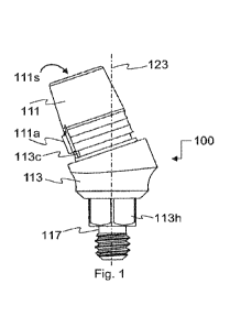
[0033] Figure 1 illustrates a side view of a dental abutment complex,
according to a
first exemplifying embodiment of the presently disclosed subject matter.
[0034] Figure lA illustrates an exploded side view showing the constituents
included
in the dental abutment complex of Figure 1, before assembled.
[0035] Figure 1B illustrates a vertical cross section view of the embodiment
shown by
Figure 1.
[0036] Figure 1C illustrates a side view of a dental abutment according to the
presently disclosed subject matter, marked with dotted lines generalizing the
relations
between its internal spaces and between a longitudinal axis of its base (which
coincides with a longitudinal axis of a dental implant which the abutment base
is
intended to be connected to).
[0037] Figure 1D illustrates a side view of a dental abutment complex,
according to a
variation of the first exemplifying embodiment of the presently disclosed
subject
matter.
[0038] Figure lE illustrates a vertical cross section view of the embodiment
shown by
Figure 1D.
[0039] Figure 1F illustrates an exploded side view showing the constituents
included
in the dental abutment complex of Figure 1D, before assembled.
[0040] Figure 2 illustrates a side view of a dental abutment complex,
according to a
second exemplifying embodiment of the presently disclosed subject matter.
[0041] Figure 2A illustrates an exploded side view showing the constituents
included
in a dental abutment complex similar to that of Figure 2 in its assembling
concept (yet
differing from that of Figure 2 in contours and proportions), before
assembled.
7
CA 03180844 2022-10-20
WO 2021/214777 PCT/IL2021/050465
[0042] Figure 2B illustrates a vertical cross section view of an assembled
dental
complex according to the embodiment shown by Figure 2B.
[0043] Figure 3 illustrates an exploded side view of a dental abutment,
according to a
third exemplifying embodiment of the presently disclosed subject matter.
[0044] Figure 3A illustrates a vertical cross section view of an assembled
dental
complex according to the embodiment shown by Figure 3.
[0045] Figure 3B illustrates a perspective view of a sleeve unit (focusing on
the distal
end of the sleeve) with an interconnecting unit inside, according to the third
exemplifying embodiment of the presently disclosed subject matter.
[0046] Figure 3C illustrates a distal end view of the sleeve unit of Figure
3B.
[0047] Figure 4 illustrate an exploded perspective view of two abutments
according
to a fifth exemplifying embodiment of the presently disclosed subject matter,
a dental
bar (referred to also milled bar) which the two abutments intend to retain,
and the
dental implants to which the abutments are to be connected.
[0048] Figure 4A illustrates a perspective view showing cross section view
through a
dental bar prepared to be retained by an abutment according to a fifth
exemplifying
embodiment of the presently disclosed subject matter, showing the bar and a
tolerated
connective complex in position on a bar's flanged aperture.
[0049] Figure 4B is a vertical cross section of the tolerated connective
complex
shown by Figure 4A, without the dental bar.
[0050] Figure 4C is a side view of the complex illustrated in the cross
section view of
Figure 4B.
[0051] Figure 4D is a vertical cross section of the tolerated connective
complex
shown by Figure 4A, with a dental bar tethered by, and with a special second
unit by
which the complex is secured to a base unit.
[0052] Figure 4E is a side view of the special second unit of Figure 4D.
[0053] Figure 4F is a cross section view about the plane Y-Y of Figure 4E.
[0054] Figure 4G is a side view of a base unit according to an embodiment of
the
presently disclosed subject matter.
[0055] Figure 4H is a cross section view about the plane K-K of Figure 4G.
8
CA 03180844 2022-10-20
WO 2021/214777 PCT/IL2021/050465
[0056] Figure 5 is a side view of a special first unit according to an
embodiment of
the presently disclosed subject matter.
[0057] Figure 5A is a cross section view about the plane L-L of Figure 5.
[0058] Figure 6 is cross section view of a hybrid first unit and a special
second unit
according to an embodiment of the presently disclosed subject matter.
[0059] Figure 6A is a side view of the embodiment illustrated by Figure 6,
illustrating
about the planes J-J and Z-Z about which the cross section of the units of
Figure 6
were taken.
9
CA 03180844 2022-10-20
WO 2021/214777 PCT/IL2021/050465
DETAILED DESCRIPTION
[0060] One technical problem dealt with by the disclosed subject matter is to
provide
a dental abutment that enables inclination of more than 10 degrees. While
dental
abutments in the market may have an inclination of more than 10 degrees, such
more
than 10 degrees abutment have disadvantages resulting from the difficulty of
treating
the screw which connects the abutment to the intended implant, through the
angulation. There are required in practice dental abutments of more than 10
degrees
angularity, in order to allow a better alignment of the abutments with other
teeth or
portions within the subject's mouth, and which yet allow a dentist to insert
the screw
into the abutment and to manipulate it, without or with minimized loss of
features as
compared to a straight abutment. Inclinations of more than 10 degrees, may not
allow
to prepare an appropriate screw channel in the abutment in line with the
implant axis,
as in straight abutments, as required for inserting a screw through the
abutment for
securing it to the implant.
[0061] In some exemplary embodiments, plain base abutments may comprise two
screw channels, requiring a conical adapter between their two parts. Working
with
such abutments is complicated and provides non-aesthetic results. Accordingly,
an
inclination of at least between 11 to 30 degrees may be required, with a
single
screwing channel and without a conical adaptor.
[0062] One technical solution is to utilize a base abutment connected directly
to the
implant (herein after referred to as Uni-Base abutment). The Uni-Base abutment
allows screwing and tightening the screw, while connecting to the implant
directly
from the upper single non-straight channel thereof. As a result, the main
screw may
not move from the top of the sleeve.
[0063] In some exemplary embodiments, the upper single non-straight channel
may
be a single screwing channel utilizing a single screw to be inserted in a
single
screwing passage within the abutment. The abutment may be connected to the
implant
by a screw that is inserted from the top of the abutment until its base for
screwing.
Therefore, there may be a threshold angle, of the abutment, that allow the
screw to
pass through. The threshold angle of the such abutments may be about 9
degrees. Uni-
CA 03180844 2022-10-20
WO 2021/214777 PCT/IL2021/050465
Base abutment may provide for a screwing method that enable inclined abutments
up
to 30 degrees.
[0064] In some exemplary embodiments, Uni-Base abutment may be made with a
single screwing channel, without the conic adaptor and it's ready for crown
cementation that is manufactured by milling by lab technologies after CAD/CAM
scanning. In some exemplary embodiments, the Uni-Base abutment may be used for
inclined implants with an angle between 11 to 30 degrees. The Uni-Base
abutment
may be comprised of an angled base with only one screwing channel (a hole
through
which a titanium screw can pass vertically), a screw that has a toothed-domed
head, a
sleeve that covers the screw's head and connected by adjacent nearly planar
surfaces,
one on the sleeve against one on the base (i.e. without cone surfaces as
conventional
two part abutments suggest) - in a non-disassembled way in a direct rotational
screwing of the sleeve itself ¨ to the inclined surface of the angled base.
The sleeve
may have on its top a screwing hole through which a screwdriver capable
diagonally
only to screw the titanium screw using his toothed-domed head. The non-
disassembled connection can be done by soldering, sticking or other
connection.
[0065] Additionally or alternatively, the sleeve may have a hole through which
a
screwdriver ¨ or any other suitable tool - capable diagonally only to screw
the screw
using his toothed-domed head. In a preferred embodiment, the sleeve may be
connected to the inclined surface, of the angled base, in non-disassembled
connection
that can be done by soldering, sticking or other connection.
[0066] In some exemplary embodiments, as the angled base and the sleeve base
are
connected in a non-disassembled way by of the direct rotating of both parts
themselves, the Uni-Base abutment may have only one screwing channel.
Moreover,
the sleeve base can have a slip or a notch that can be inserted into a grove
in the
angled base to stabile the connection and avoid direct rotation. While using
the
universe, it assembled in one unit. Additionally or alternatively, a crown may
be built
on the sleeve, and the whole unit is screwed by using the screwdriver (or
other
suitable tool) via the upper opening of the sleeve, to tighten the Uni-Base
abutment
directly to the implant itself.
[0067] Another technical solution is a Clicq-Base abutment for dental implants
that
can be used either inclined or vertical. The Clicq -Base may be comprised of
an angled
11
CA 03180844 2022-10-20
WO 2021/214777 PCT/IL2021/050465
base, which can be horizontal, a screw to tighten the angled base (meanwhile
the
crown can be built on the Sleeve) and a cylinder with screw thread on each
end, one is
right hand thread and the other is left hand thread. The upper side of the
cylinder may
be a hole shaped in a way that enables to use a tool to rotate it, such as a
hexagon, or
the like. The base and the sleeve may have screw threads inside in relation to
the
cylinder threads. The sleeve can have a slip that can be inserted into a grove
in the
angled base to stabile the connection.
[0068] In some exemplary embodiments, the sleeve with the crown can be
connected
to the angled (or horizontal) base, using the cylinder in between and rotated
by a
suitable tool and due to the two kinds of threads the sleeve is tightened to
the base.
[0069] In some exemplary embodiments, the sleeve and the base are connected by
mating threads, and the crown is connected partly to an externally facing
surface of
the sleeve and partly on an external surface of the base, which is disposed
facing away
from a longitudinal axis common to the sleeve and to a proximal wall of the
base,
whereby in vivo pivoting of the sleeve with respect to the base is prevented
since the
crown is connected to both the sleeve and the base.
DETAILED DESCRIPTION OF THE FIGURES
[0070] Figure 1 illustrates a side view of a dental abutment 100, according to
a first
exemplifying embodiment of the presently disclosed subject matter. The
abutment,
comprising first and second units, 113 and 111, respectively, is illustrated
in this
figure as an assembled ready to use abutment complex. Figure lA illustrates an
exploded side view showing the constituents included in the dental abutment
complex
of Figure 1, before assembled. The cross section view in Figure 1B facilitates
understanding the interrelations between the constituents of the complex.
[0071] In the embodiment exemplified in these three figures, the second unit,
111,
(referred to also herein 'sleeve') is adapted to be connected to the first
unit 113
(referred to also herein 'base') permanently, i.e., by a non-separable
connective
method, e.g., welding, soldering, gluing, or sticking (either of which may be
destructive to the abutment constituents, in case separated forcefully).
Mutual
protrusion and groove notches created respectively on the first and the second
units,
facilitate alignment of the first and the second units and stabilize the
abutment during
12
CA 03180844 2022-10-20
WO 2021/214777 PCT/IL2021/050465
their welding (or gluing) process, and may contribute also to future stability
of the
abutment complex by resisting relative rotation between the two units.
[0072] The notch (either protrusion or indentation) within the sleeve 111 is
hidden
from the dentist when integrating the two unis together, since it is located
on the
inside of the sleeve. For ease of identification, the location of the notch
(either
protrusion or indentation) within the sleeve 111, can be hinted by a mark,
such as
bulge 111a, formed on the outer surface of the sleeve. The mutual notch 113c,
on the
base 113, is visible to the dentist, thus may not require a hint for
identifying its
location.
[0073] Once assembled onto an in vivo dental implant, a crown can be built on
the
sleeve 111.
[0074] The complex constituting the dental abutment 100, can be either
connected to
or removed from the implant by rotating the screw 117 in the relevant
direction
(clockwise or counterclockwise, for advancing or receding the thread helix
117b into
or out from the implant). The access to the screw for rotating it, is via the
upper
opening 111s of the sleeve 111. This may be accomplished even after the first
and
second units became permanently assembled, with the assistance of an
intermediation
tool 119 (seen in Figures lA and 1B). The intermediation tool 119, may have a
conventionally contoured proximal end (e.g., hexagonal recess 119s) to be
manipulated by a conventional screwdriver in common use by dentists. The
distal end
of the intermediation tool 119 is configured for being mutually geared with a
head
117a of the screw 117, whereby rotation of the screwdriver about a
longitudinal axis
123a of the sleeve 111, is transmitted by the gearing between intermediation
tool 119
and the head 117a of the screw 117, into rotation of the screw 117 about the
longitudinal axis 123, which is common to the base and to the implant. In the
illustrated embodiment the head 117a of the screw 117 is rounded and designed
to be
partially wrapped by the distal end 119G of intermediation tool 119, thus may
be too
small in diameter to secure the base 113 to an intended dental implant. The
screw 117
may therefor comprise a peripheral widening 117W, resembling the bottom end of
a
conventional screw head (such as head 218a of screw 218). The peripheral
widening
117W is intended to lean on the inward narrowing 113N (formed at the proximal
end
of anti-rotation hexagonal member 113h) in the base unit 113.
13
CA 03180844 2022-10-20
WO 2021/214777 PCT/IL2021/050465
[0075] Before the second unit 111 is permanently connected to the first unit,
a dentist
making use of the abutment 100, benefits from direct access to the screw. The
screw
head 117a is exposed at the opening 113s of the base 113, and the screw can
thus be
easily controlled by a matching screwdriver. Meanwhile, in embodiments in
which
the sleeve 111 is to be attached to the base 113 by gluing and/or by sticking,
a dental
crown may be prepared and built onto the second unit.
[0076] Regardless of whether the dentist opts to integrate the second unit
with the
first only after the dental crown is already built on the second unit, the
indirect access
to the screw, through the opening 111s of the sleeve and with the assistance
of the
intermediation tool 119, allows the dentist to connect and disconnect the
abutment to
and from the dental implant, whenever required.
[0077] The abutment complex 100 comprises a single screw channel, 113a, being
a
screw bore extending through the first unit 113, to be sharing with an
intended
implant the same longitudinal axis 123, and located in the region between the
dashed
lines 113a1 and 113a2 in Figure 1A. As can be appreciated, once integrated
with the
first unit 113, the second unit 111 prevents removal of the screw 117 from the
abutment complex 100, due to the angular orientation of the second unit 111
with
respect to the first unit 113. Due to said angular orientation, the sleeve-
like wall of the
second unit, extends (in the wall region 130, which is intersected by the axis
123, see
Figure 1C) across the screw channel thus blocking the way of the screw out of
the
abutment. The dentist yet can manipulate the screw 117 through the
intermediation
tool 119, which may be concealed within the sleeve 111.
[0078] Conventional one-piece angular abutments, allow a dentist to manipulate
the
screw by having their screw channel extending linearly through the angled
portion to
which the dental prosthesis is to be attached. In conventional angular
abutments, this
angled portion is therefore produced sufficiently massive to accommodate a
diagonally disposed screw hole. In contrast to that, the second unit 111 may
lack a
diagonally disposed screw hole and may thus be formed as a tubular hollow
sleeve
having thinner wall and more compact construction than that of said
conventional
one-piece angular abutments. A more compact construction of the prosthesis
support
member, as may be provided according to the presently disclosed subject
matter, may
provide a dentist with more freedom in designing the prosthesis and may
eliminate
14
CA 03180844 2022-10-20
WO 2021/214777 PCT/IL2021/050465
extensive grinding work which may be required in conventional abutments for
making room for the intended prosthesis.
[0079] Referring now specifically to Figure 1A, the constituents of the dental
complex embodiment 100 of Figure 1, are illustrated separately, yet oriented
about
two angularly spaced axes 123 and 123a, with an angle a in between. The axis
123 is
overlapping with the longitudinal axis of a dental implant to which the
complex is
intended to be connected to in vivo. The axis 123a is the longitudinal axis of
the
sleeve unit 111. In manufactured embodiments, the angle a may be between 0 and
about 30 degrees, e.g., 0 degrees, 10 degrees, 11 degrees, 15 degrees, 20
degrees, 25
degrees and the like, depending on market demands. The same sleeve unit 111
may be
used regardless of the angle a, which may be determined according to the
design of
the base unit 113 only, without affecting the design of the sleeve unit 111.
The angle
between the supportive surface 113b and the axis 123, determines the
inclination of
the sleeve unit 111 about axis 123, because the contact surface 111b of the
sleeve 111
which is designed to seat on the supportive surface 113b, is contoured to be
tangential
to a plane perpendicular to the axis 123a. Consequently, the inclination of
surface
113b to the axis 123, determines the inclination of axis 123a to axis 123,
expressed by
the angle a.
[0080] As can be appreciated from the figure, the sleeve 111 and the tool 119,
are in
alignment with the axis 123a, while the base unit 113 and the screw 117, are
in
alignment with the axis 123, in reflection to their orientation in the
assembled
complex 100, and as also shown in the cross section view of Figure 1B.
[0081] The screw 117 has a domed head 117a, grooved to form a plurality of
teeth
(e.g., 6 teeth) angularly spaced about the axis 123, and rounded according to
the round
contour of a dome top constituting the domed head 117a. The teeth are
contoured and
dimensioned to be geared with a teethed distal end 119G of the intermediation
tool
119.
[0082] The base unit 113, comprises a collar 113k for facilitating the
assembling of
the sleeve 111 with the base 113. A notch 113c may be formed on a desired
location
on the collar 113k, in match with an indentation formed inside the sleeve 111,
for
facilitating positioning and for preventing the sleeve unit from pivoting with
respect
to the base once assembled. The location of the notch within the collar may be
hinted
CA 03180844 2022-10-20
WO 2021/214777 PCT/IL2021/050465
by a protrusion 111a formed on the outer surface of the sleeve, in alignment
with the
location of the notch.
[0083] Figure 1D illustrates a side view of a dental abutment complex 150,
according
to a variation of said first exemplifying embodiment of the presently
disclosed subject
matter. The distal portion of the base unit 113D the screw 117, and
intermediation
tool 119D, are like the distal portion 113 of the base unit, the screw and the
intermediation tool of the embodiment of Figure 1 (in variation embodiment
150, the
intermediation tool 119D is more compact in length than 119 in embodiment 100,
and
has smaller diameter in its proximal portion, in comparison to a larger
diameter in its
distal portion. Consequently, the edge of the thread member 111t, may be
utilized for
restricting linear dispositioning of the intermediation tool 119D further into
the
hollow of the sleeve). The embodiment of Figure 1 and its variation in Figure
1D,
differ, however, in the connection method between the first unit and the
second unit.
This may reflect also on the rotation preventive preparation structure, which
is a
structural arrangement in the abutment assembly, by which the second unit may
be
secured from pivoting about its longitudinal axis when in vivo forces may
exert pivot
causing stresses on the abutment, through the prosthesis constructed on and
supported
by the abutment. While in the embodiment 100, the rotation preventive
preparation
structure may include matching rotational symmetry breaking male-female
contours,
such as notch 113c and a mutual indentation (like 311i in Figure 3B), and/or a
welding by which the first and second units unite, in the embodiment 150 of
Figure
1D, the rotation preventive preparation structure includes the outwardly
facing surface
113u of the base unit 113D, and the outwardly facing surface of the sleeve
unit 111u.
In various embodiments, the rotation preventive preparation structure includes
also
the bulge 113p which protrudes from the outwardly facing surface 113u.
[0084] The outwardly facing surface 113u of the base unit 113D, is an outer
surface
of a wall which elevates from surface 113q, as an extended collar. The
outwardly
facing surface of the sleeve unit 111u is the outer surface of the wall of
sleeve 111D.
[0085] Referring now to Figures 1D to 1F, it can be appreciated that in the
illustrated
variation, the connection between the base unit 113D and the sleeve unit 111D,
is by
mating threads 111t (an outer thread on a cylindrical connective member of the
sleeve
emerging from the distal end of the sleeve 111D) and 113t, which is formed as
an
inner thread inside the proximal opening 113s of the extended base unit 113D.
The
16
CA 03180844 2022-10-20
WO 2021/214777 PCT/IL2021/050465
sleeve unit 111D may be provided with a special contour such as a hexagonal
contour
111j in match with a screwdriver, for facilitating the assembling of the
second unit
with the first by said threads, as well as for facilitating separation of the
two units
when needed.
[0086] Once the base unit 113D and the sleeve unit 111D are assembled together
and
to an intended dental implant, the surfaces 113u and 111u, may constitute
together an
infrastructural support for the construction of a tooth prosthesis. The
prosthesis can be
attached to the surfaces 113u and 111u by satisfactorily firmly adhesion,
whereby
pivoting the sleeve unit with respect to the base unit under in vivo forces
exerted on
the prosthesis, is prevented. The protrusion 113P (which differently from
other
embodiments of the presently disclosed subject matter, protrudes from a wall
of the
base unit 113D, rather than from an outer surface of the sleeve) is intended
to protrude
into the prosthesis as an anchor, thus reducing furthermore risk of relative
pivoting
between base unit 113D and the sleeve unit 111D.
[0087] Since the surfaces 113u and 111u, may constitute together an
infrastructural
support for the construction of a tooth prosthesis which corresponds to the
infrastructural support which the sleeve 111 alone provides in the embodiment
100,
the embodiment 100 and its variation 150, may differ in proportions. This is
because
for same size abutments, the sleeve 111D may be shorter than the sleeve 111,
as a
function of the height of wall surface 113u from above the surface 113q of the
base
unit 113D. As an unbinding example, the ratio 'sleeve height' (from contact
surface
111b to opening 111s) to 'base unit extended collar height' (from surface 113q
up to
supportive surface 113b), may be about 3:2 (i.e., 1.5).
[0088] Consequently, the proportions between a total height of the sleeve unit
and a
total height of the base unit may differ between the embodiment 100 and its
variation
150, per same total height of the abutment assemblies 100 and 150.
[0089] For reasonable anti-rotation results, said ratio may vary between 0.3 -
3.
[0090] Referring now to Figures 2 and 2A, two dental abutment complexes 200T
and
200, according to a second exemplifying embodiment of the presently disclosed
subject matter are disclosed, respectively. Said two dental abutment complexes
differ
one from another in contours and proportions as reflected from the Figures,
yet both
share the same assembling concept. The main differences are in that the sleeve
unit
17
CA 03180844 2022-10-20
WO 2021/214777 PCT/IL2021/050465
211T is of a type partly truncated at its proximal portion (see right top of
Figure 2),
and that the base unit 213T has an extended cone contoured portion from above
the
anti-rotation hexagon 213h in comparison to the sleeve unit 211 of Figure 2A.
In the
remaining of the description, references made to 211 apply also to 211T, and
references made to 213 apply also to 213T. The screw 218T of the abutment
complex
200T differs in proportions from screw 218 of abutment complex 200. In the
remaining of the description, references made to 218 apply also to 218T, and
vice
versa.
[0091] The embodiment represented by the two types 200T and 200, differs from
the
embodiment of Figure 1, in having the sleeve 211 removably connectible to the
base
unit 213, by means of an interconnecting unit 220 (referred to also 'cylinder
screw').
The interconnecting unit comprises threads on its opposite ends. A first outer
thread
220R is on the proximal end of the interconnecting unit 220, and is mating
with an
inner thread 211R (shown in the cross section view of Figure 2B) formed within
the
sleeve unit 211, e.g. in the distal half thereof. A second outer thread 220L
is on the
distal end of the interconnecting unit 220, and is mating with an inner thread
213L
(shown in the cross section view of Figure 2B) formed within the base unit
213, in the
proximal half thereof.
[0092] In various embodiments of the presently disclosed subject matter one of
the
threads 220R and 220L, e.g., 220R is a right-hand thread, and other, 220L is a
left-
hand thread. Due to the two kinds of threads, the sleeve 211 can be tightened
to the
base 213 by rotating the interconnecting unit 220 via the upper opening 211s
of the
sleeve 211.
[0093] Referring now specifically to Figure 2A, the constituents of the dental
complex embodiment 200, are illustrated separately, yet oriented about two
angularly
spaced axes 223 and 223a, with an angle a in between. The axis 223 is
overlapping
with the longitudinal axis of a dental implant to which the complex is
intended to be
connected to in vivo. The axis 223a is the longitudinal axis of the sleeve
unit 211. In
manufactured embodiments, the angle a may be between 0 and about 30 degrees,
e.g.,
0 degrees, 10 degrees, 11 degrees, 15 degrees, 20 degrees, 25 degrees and the
like,
depending on market demands. The same sleeve unit 211 may be used regardless
of
the angle a, which may be determined according to the design of the base unit
213
18
CA 03180844 2022-10-20
WO 2021/214777 PCT/IL2021/050465
only, without affecting the design of the sleeve unit 211. The angle between
the
supportive surface 213b and the axis 223, determines the inclination of the
sleeve unit
211 about axis 223, because the distal edge 211b of the sleeve 211 which
constitutes a
contact surface designed to seat on the supportive surface 213b, is contoured
to be
tangential to a plane perpendicular to the axis 223a. Consequently, the
inclination of
supportive surface 213b to the axis 223, determines the inclination of axis
223a to
axis 223, expressed by the angle a.
[0094] The base unit 213, comprises a collar 213k, and the sleeve-like design
of the
sleeve unit 211, comprises a widening 211W formed on the distal end of the
sleeve
unit. Once the base and the sleeve units are fully assembled together, the
sleeve
widening 211W covers the collar 213k. A notch 213c may be formed on a desired
location on the collar 213k, in match with an indentation formed inside the
widening
211W, for facilitating positioning and for preventing the sleeve unit from
pivoting
with respect to the base once assembled. The location of the notch within the
collar
may be hinted by a protrusion 211a formed on the outer surface of the sleeve,
in
alignment with the location of the notch.
[0095] The interconnecting unit 220 comprises at its proximal end 220a a
hexagonal
indentation (see 220s on Figure 2B) like a conventional screw, or may have any
other
desired screw head, to facilitate its rotation by a matching screwdriver. The
sleeve
211 comprises an opening 211s at it proximal end, through which a conventional
screwdriver may be inserted for manipulating the interconnecting unit 220.
[0096] As can be appreciated, the embodiments 200T and 200 allow removal and
replacement of the sleeve 211 whenever required, without disconnecting the
base unit
213 from the implant, hence without exposing the implant and its surroundings
to the
risk of contamination. This feature allows a dentist to connect the base unit
to the
implant (by advancing the thread helix 218b into the implant) by a screwdriver
with
direct access to the head 218a of the screw 218, through the opening 213s at
the
proximal end of the base unit, in the absence of the sleeve unit 211. The
sleeve unit
can then by temporarily secured to the base unit using the interconnecting
unit 220,
for taking required measurements and/or photos, then removed.
[0097] A healing cap having an outer thread mating with the inner thread 213L
may
then be secured to the base unit for a healing period. Meanwhile, the sleeve
unit 211
19
CA 03180844 2022-10-20
WO 2021/214777 PCT/IL2021/050465
may separately be subjected to crown building process. Once healed, the
dentist can
replace the healing cap by the sleeve unit with the already prepared crown,
without
manipulating the base unit, hence without exposing the implant and its
surroundings
to the risk of contamination.
[0098] Restoration of the crown and/or the prosthesis becomes a reasonable
option
whenever needed, with the embodiments 200T and 200, since there is no need to
intervene with the cone-based connection between the abutment and the dental
implant, as the base unit 213 need not be separated from the implant. This
transfers
the restoration treatment from the bone level to the tissue level,
significantly
increasing the likelihood of successful restoration procedure.
[0099] Referring now to Figure 3, a third exemplifying embodiment 300 of the
presently disclosed subject matter is illustrated in an exploded side view.
Like in the
embodiments 200T and 200, the sleeve unit 311T is removably connectible to the
base unit 313. Yet, while in the embodiments 200T and 200 the sleeve has an
internal
thread 211R mating with the external thread 220R on the proximal end of the
interconnecting unit 220, in the embodiment 300, the sleeve unit 311T is
removably
connectible to the interconnecting unit 320a (referred to also as 'cylinder
screw') by
means of conventional screw 320c. The screw 320c may be inserted through the
proximal opening 311s of the sleeve unit 311T and is to be manipulated through
same
opening by a matching screwdriver. The conventional outer thread of the screw
is
mating with internal thread formed within the interconnecting unit 320a, as
appreciable from the cross section view in Figure 3A.
[0100] In various embodiments of the interconnecting unit 320a, the screw 320c
is
welded to the interconnecting unit 320a, at the location 320b (at the
peripheral region
of the distal end of the screw 320c). For the welding, the screw 320c is first
inserted
through the opening 311s of the sleeve 311T. The interconnecting unit 320a is
then
inserted through the opposite (distal) end of the sleeve 311T, and the screw
is driven
into the internal thread of the interconnecting unit, until its distal end
starts emerging
out of the internal thread of the interconnecting unit 320a, thus reaching the
location
of welding 320b. The screw and the interconnecting unit are then welded at the
peripheral region 320b of the distal end of the screw. Once welded, the
assembly
comprising the screw 320c and the interconnecting unit 320a is trapped to the
sleeve
unit 311T (yet can freely rotate) due to an inward peripheral rim 311r formed
inside
CA 03180844 2022-10-20
WO 2021/214777 PCT/IL2021/050465
the sleeve unit and having an internal diameter smaller than the lateral
widths of both
the screw head 320h and of the interconnecting unit 320a.
[0101] Inside the sleeve 311T there is ring-like shoulder (referred to also as
an
"undercut step") 311r for supporting the screw 320c when rotated by a
screwdriver for
driving the outer thread of the interconnecting unit 320a (which is welded to
the
screw, thus co-rotating with the screw) into its mating thread 313L inside the
proximal half of the base unit. Upon tightening the screw, the sleeve unit
311T
becomes tightened to the base unit 313. It can then be disconnected from the
base unit
whenever desired, by driving the screw in the opposite direction. Like the
embodiment of Figure 2, the base may have a collar 313k with a notch 313c, and
the
sleeve 311T may have a widening 311W with internal matching notch 311i, the
widening 311W adapted to wrap the collar 313k. The supportive surface 313b
from
which the collar 313k is elevating, may be inclined to the longitudinal axis
323,
whereby the angle a is created between the axis 323a of the sleeve 311T and
the axis
of the base 313.
Referring now to Figures 4 ¨ 4H, an embodiment for retaining a milled bar 401
to a
plurality of dental implants, e.g. Implant 1 and Implant 2, is illustrated.
The milled bar
may be produces e.g., by CadCam milling in a dental lab, after scanning the
base units
in vivo by a scan abutment. Two or more fixed holes are typically milled, e.g.
four
holes. The bar may then be connected by hand to a tolerated connective complex
utilizing the bar holes. As explained hereinafter, the tolerated connective
complex
uses screwing and/or click technique with ball friction joints, which enable
connection
and adjusting of the bar while compensating against any inaccuracy in bar hole
positions.
[0102] The milled bar 401 has through holes such as 401n and 401m in a
plurality of
locations. Inside each hole there is an inner rim 401a. A threaded cap 431, is
to be
inserted into each hole from a proximal end of the bar. The cap thread is an
inner
thread 43 it, mating with an outer thread formed on a split nut 434 (split by
two or
more lateral through cuts 434c), to be inserted from a distal end of the bar.
Each split
nut 434 has an inner peripheral indentation 434r contoured and dimensioned to
capture a ball head 432a of a tolerated connective unit 432. The tolerated
connective
unit comprises said ball head at a proximal end of the tolerated connective
unit, and is
further comprising a split ball head 432b (split by the lateral through cut
432c) at a
21
CA 03180844 2022-10-20
WO 2021/214777 PCT/IL2021/050465
distal end of the tolerated connective unit, and a narrowing body member 432n
connecting between the ball head 432a and the split ball head 432b. The
tolerated
connective unit 432 further comprises a screw channel extending through the
ball
head, the narrowing body member and the split ball head, with an inner thread
extending at least through a portion of said screw channel. The screw channel
and a
screw 433, are mutually dimensioned and contoured to cause the split ball head
432b
to expand laterally with an amount of expansion depending on the linear
position of
the screw 433 inside the screw channel, such that when the screw is fully
screwed, the
split ball head is fully pressed by the screw from inside, thus fully
expanded. When
there is no stress from the screw (screw is released) the split ball head 432b
returns to
its unstressed, normally contracted, position due to the spring-like
characteristics of
the metal from which it is made.
[0103] The screw 433 may be inserted into the screw channel of the tolerated
connective unit, through an opening 431s formed in the proximal end of the
threaded
cap 431. Through same opening 431s, the screw can be driven by a matching
screwdriver. Rotation of the threaded cup may be facilitated by having is
opening
431s with a polygonal contour 431h, e.g., a hexagonal opening in match with a
conventional hexagonal screwdriver.
[0104] The opening 431s, may have a hexagonal contour (or any other desired
contour) in match with a second screwdriver, whereby the threaded cap itself
may be
rotated for securing it with the split nut 434. The inner thread of the
threaded cap and
the outer thread of the split nut 434 are contoured and dimensioned for
contracting the
split nut by forcing its splits inwardly, with an amount of contraction
reaching a
maximum when the threaded cap and the split nut are fully screwed together.
When
there is no stress from the screw (screw is released) the split ball head 432b
returns to
its unstressed, normally contracted, position due to the spring-like
characteristics of
the metal from which it is made.
[0105] When there is no stress from the threaded cap 431 (threaded cap is
released),
the split nut 434 returns to its unstressed, normally expanded, position due
to the
spring-like characteristics of the metal from which it is made.
[0106] The amount contraction of the split nut 434 upon closing the threaded
cap 431
on it, is adapted for narrowing the inner peripheral indentation 434r in such
amount
22
CA 03180844 2022-10-20
WO 2021/214777 PCT/IL2021/050465
such that once the threaded cap is fully screwed to the split nut 434, wall
portions of
the peripheral indentation are forcefully pressing on the ball head, such that
the ball
head 432a is firmly and immovably seized within the recess by friction caused
from
said forcefully pressing.
[0107] The narrowing 432n, in the body of the tolerated connective member,
allow a
predetermined degree of freedom in the orientation in which the tolerated
connective
member 432 is immovably seized once the threaded cap 431 is fully secured to
the
split nut 434. Said degree of freedom is exemplified in Figure 4A by the
virtual-cone
VC having cone base 440p on a selected predetermined plane. The virtual-cone
is
delineated by a longitudinal axis 440a of the tolerated connective unit 432,
passing
through the predetermined plane when the tolerated connective member takes its
extreme allowed inclination with respect to a middle location, in any
direction such
inclination is allowed. The degree of inclination is represented by the angle
13 between
the longitudinal axis 440a when in the middle, and the axis 440e (which is
another
title for the axis 440a) when the unit 432 is tilted to an extremely allowed
orientation.
In various embodiments of the disclosed subject matter, the angle b may be 5
degrees,
with a precision of between 5 ¨ 10 percent.
[0108] Referring now to the tethering of the tolerated connective unit 432 to
the base
unit according to the presently disclosed subject matter, two different base
units are
depicted in Figure 4. A first base unit 413x has its surface 413b
perpendicular to the
longitudinal axis of an in vivo Implant 1, which is substantially in alignment
with hole
401n in the milled bar 401. A second base unit 413y, has its surface 413b
inclined to
the longitudinal axis of an in vivo Implant 2, by an angle other than 90
degrees, for
compensating against a certain deviation of the longitudinal axis of Implant
2, from
alignment with hole 401m in the milled bar 401.
[0109] The two base units 413x and 413y are to be connected to the implants,
respectively, each by a screw 418. A second unit 411m, which is a special
second unit
(referred to also as 'multi-base adapter'), may then be connected (e.g., in
substitution
of healing caps, after a healing period as described above regarding
previously
explained embodiments) to the proximal end of each base unit, e.g., by an
integral
interconnecting unit 411t having external thread mating with internal thread
of the
base unit.
23
CA 03180844 2022-10-20
WO 2021/214777 PCT/IL2021/050465
[0110] Each special second unit 411m has inside a proximal portion thereof
411p, a
peripheral indentation 411r contoured and dimensioned to capture the split
ball head
432b of the tolerated connective unit 432, which emerges out of the distal end
of each
split nut 434 to enter the special second unit 411 through its proximal
opening 411s.
The split ball head 432b can be easily pushed into the proximal opening 411b
of a
respective special second unit 411m, when the screw 433 is in retracted linear
position, i.e., when the screw 433 is at least partially released, and the
split ball is in a
contracted state, or at least in a semi contracted state.
[0111] Once the split ball is accommodated within the inner peripheral recess
in the
proximal portion of special second unit 411m, and the respective threaded cap
431 is
released, its orientation can be changed freely within the boundaries of its
virtual-cone
VC. Once all the plurality of holes of the milled bar 401 to be retained are
prepared
each with its respective tolerated connective member 432 in place yet before
secured,
the dentist can decide on a most preferred position of the milled bar 401
within the
tolerance given by the plurality of tolerated connective member 432, and then
secure
the screw 433 of each, for thereby expand the respective split ball head 432b
to the
maximum allowed, thus creating a seizing pressure between the split ball head
432b
and the internal peripheral indentation 411r, thereby locking each tolerated
connective
member 432 in its present orientation, making it immovably secured to the
special
second unit 411m, and hence immovably tethered to the respective dental
implant.
[0112] The milled bar 401 can then be secured to the tolerated connective
member
432 by fully securing each of the threaded caps 431 to its split nut 434,
thereby
immovably seizing each ball head 432a within the respective split nut 434.
[0113] The milled bar thus becomes immovably tethered to the plurality of
implants,
with the inner rims 401a captured each in between the distal edge of the
respective
threaded cap and the shoulder 434a of the respective split nut.
[0114] The milled bar can then be removed whenever required, simply by
removing
the threaded caps 431, and return when desired, exactly to its original
position, simply
by placing it back on the ball heads 432a and resecuring the threaded caps.
[0115] Referring now to Figures 5 and 5A, a special first unit (referred to
also as
'short adapter') 513m, for tethering the tolerated connective member 432
directly to an
implant without intermediation of the special second unit 411m, is disclosed.
The
24
CA 03180844 2022-10-20
WO 2021/214777 PCT/IL2021/050465
special first unit comprises a peripheral indentation 513r at its proximal
portion,
corresponding to the peripheral indentation 411r in the special second unit
411m, and
an integral screw 519 for connecting the unit 513m directly to the intended
implant.
The unit is especially useful in cases where a gap between the bar 401 and an
implant,
does not allow the use of a base unit such as 413x and 413y in combination
with the
special second unit 411m.
[0116] Referring now to Figures 6 and 6A, an embodiment comprising a hybrid
first
unit (referred to also as 'multi-unit adapter') 613m, is disclosed. The hybrid
first unit
613m has an integral screw 619m for directly connecting to an intended
implant, like
the special first unit of the embodiment of Figure 5, yet differs from said
embodiment
in that the peripheral recess 611m for seizing the split ball head 432b is
formed in the
proximal end of a special second unit 611m, which corresponds to the special
second
unit 411m of the embodiment of Figure 4. The special second unit 611m
comprises an
opening 611s at its proximal end, for receiving the split ball head, and an
outer thread
611t directed towards its distal end, mating with an inner thread 613t located
at the
proximal end of the hybrid first unit 613m.
[0117] The corresponding structures, materials, acts, and equivalents of all
means or
step plus function elements in the claims below are intended to include any
structure,
material, or act for performing the function in combination with other claimed
elements as specifically claimed. The description of the present invention has
been
presented for purposes of illustration and description, but is not intended to
be
exhaustive or limited to the invention in the form disclosed. Many
modifications and
variations will be apparent to those of ordinary skill in the art without
departing from
the scope and spirit of the invention. The embodiment was chosen and described
in
order to best explain the principles of the invention and the practical
application, and
to enable others of ordinary skill in the art to understand the invention for
various
embodiments with various modifications as are suited to the particular use
contemplated.