Note: Descriptions are shown in the official language in which they were submitted.
CA 03181054 2022-10-24 -
DESCRIPTION
Title of the Invention: CARBON DIOXIDE REDUCTION CATALYST AND
CARBON DIOXIDE REDUCTION METHOD
TECHNICAL FIELD
[0001]
The present invention relates to a carbon dioxide
reduction catalyst and a method for reducing carbon dioxide.
BACKGROUND ART
[0002]
Carbon dioxide (CO2) is one of the substances emitted into
the atmosphere by the combustion of fuel. Since carbon dioxide
may contribute to global warming, carbon dioxide emissions
into the atmosphere are regulated by international conventions
on climate change, etc. Therefore, technologies have been
proposed to convert carbon dioxide into industrially useful
substances in order to decrease carbon dioxide emissions into
the atmosphere.
[0003]
For example, a technology for converting carbon dioxide to
methanol, which has been widely used as a raw material for
various industries, has been known. In industrial use, for
example, there has been known a method for converting a gas
containing carbon dioxide and hydrogen to methanol by a
Date Regue/Date Received 2022-10-24
CA 03181054 2022-10-24 -
2
reduction reaction using a copper-zinc catalyst under
conditions of 250 C or more and 50 atm or more. However, this
method has a problem of high energy cost since it requires
high-temperature and high-pressure conditions for the
reaction. Furthermore, the method also has a problem of an
insufficient methanol selectivity since water produced by the
reaction lowers a catalytic activity. Therefore, there is a
need to develop a technology for a carbon dioxide reduction
catalyst that can produce methanol at a low cost and achieve a
satisfactory methanol selectivity.
[0004]
Patent Document 1: Chinese Patent Application Publication
No. 106076396
[0005]
Patent Document 1 discloses a technology concerning a
method for preparing an Au-Cu-supported mesoporous catalyst in
which Au-doped Cu is supported on mesoporous silica (N112-SBA-
15) serving as a catalyst for use in production of methanol by
a reduction reaction Of carbon dioxide. However, the
technology disclosed in Patent Document I has a problem of an
insufficient methanol selectivity in the reduction reaction of
carbon dioxide.
DISCLOSURE OF THE INVENTION
Problems to be Solved by the Invention
[0006]
Date Regue/Date Received 2022-10-24
CA 03181054 2022-10-24 -
3
The present inventors conducted extensive studies to
improve a carbon dioxide reduction catalyst and have found a
carbon dioxide reduction catalyst exhibiting an excellent
methanol selectivity.
[0007]
The present invention has been made in view of the above-
described problem, and an object thereof is to provide a
carbon dioxide reduction catalyst for use in a reduction
reaction of carbon dioxide, the catalyst exhibiting a high
methanol selectivity.
Means for Solving the Problems
[0008]
The present invention relates to a carbon dioxide
reduction catalyst for use in production of methanol by a
reduction reaction of carbon dioxide, the catalyst including
Au and Cu serving as catalyst components and ZnO serving as a
support.
[0009]
The catalyst Components preferably include 2 to 25 % by
mole of the Au.
[0010]
For the above-mentioned carbon dioxide reduction catalyst,
a methanol selectivity in reduction of carbon dioxide is
preferably 80% or more.
[0011]
Furthermore, the present invention relates to a method for
Date Regue/Date Received 2022-10-24
CA 03181054 2022-10-24 -
4
reducing carbon dioxide including reducing carbon dioxide
using the above-mentioned carbon dioxide reduction catalyst
under a condition of 50 bar or less to thereby produce
methanol.
[0012]
Furthermore, the present invention relates to a method for
reducing carbon dioxide including reducing carbon dioxide
using the above-mentioned carbon dioxide reduction catalyst
under a condition of 240 C or less to thereby produce
methanol.
Effects of the Invention
[0013]
The carbon dioxide reduction catalyst of the present
invention exhibits a higher methanol selectivity in a
reduction reaction of carbon dioxide compared to the related
art.
BRIEF DESCRIPTION OF THE DRAWINGS
[0014]
FIG. 1 is a graph showing a methanol selectivity, a
methanol production rate, and a carbon monoxide production
rate for the carbon dioxide reduction catalysts of Examples
and Comparative Examples;
FIG. 2 is a graph showing a methanol selectivity, a
methanol production rate, and a carbon monoxide production
rate for the carbon dioxide reduction catalysts of Examples;
Date Regue/Date Received 2022-10-24
CA 03181054 2022-10-24 -
FIG. 3 is a graph showing a methanol selectivity, a
methanol production rate, and a carbon monoxide production
rate for the carbon dioxide reduction catalysts of Examples;
FIG. 4 is a graph showing a methanol selectivity, a
methanol production rate, and a carbon monoxide production
rate for the carbon dioxide reduction catalysts of Examples;
FIG. 5 is a graph showing a methanol selectivity, a
methanol production rate, and a carbon monoxide production
rate for the carbon dioxide reduction catalysts of Examples;
FIG. 6 is a graph showing a methanol selectivity, a
methanol production rate, and a carbon monoxide production
rate for the carbon dioxide reduction catalysts of Example and
Comparative Examples;
FIG. 7 is a graph showing a methanol selectivity, a
methanol production rate, and a carbon monoxide production
rate for the carbon dioxide reduction catalysts of Example and
Comparative Examples;
FIG. 8 is a graph showing a methanol selectivity, a
methanol production rate, and a carbon monoxide production
rate for the carbon dioxide reduction catalysts of Example and
Comparative Examples;
FIG. 9 is a graph showing a methanol selectivity for the
carbon dioxide reduction catalysts of Examples and Comparative
Examples;
FIG. 10 is a graph showing a methanol selectivity for the
carbon dioxide reduction catalysts of Examples;
Date Regue/Date Received 2022-10-24
CA 03181054 2022-10-24 -
6
FIG. 11 is a TEN image of a carbon dioxide reduction
catalyst of Example;
FIG. 12 is a graph showing the result of a TEM-EDS
analysis of the carbon dioxide reduction catalyst of Example;
FIG. 13 is a graph showing the results of an XRD analysis
of the carbon dioxide reduction catalysts of Examples;
FIG. 14 is a chart showing the result of a Mossbauer
analysis of Comparative Example;
FIG. 15 is a chart showing the result of a Mossbauer
analysis of Example;
FIG. 16 is a chart showing the result of a Mossbauer
analysis of Example;
FIG. 17 is a chart showing the result of a Mossbauer
analysis of Example;
FTC. 18 is a chart showing the results of an XAFS analysis
of Examples and the like;
FIG. 19 is a chart showing the results of an XAFS analysis
of Examples and the like;
FIG. 20 is a chart showing the results of an XAFS analysis
of Examples and the like;
FIG. 21 is a chart showing the results of an XAFS analysis
of Examples and the like;
FIG. 22 is a HAADF-STEm image of the carbon dioxide
reduction catalysts of Example 5;
FIG. 23 is a HAADF-STEM image of the carbon dioxide
reduction catalysts of Example 8;
Date Regue/Date Received 2022-10-24
CA 03181054 2022-10-24 -
7
FIG. 24 is a HAADF-STEM image of the carbon dioxide
reduction catalysts of Example 9;
FIG. 25 is a graph showing a methanol selectivity, a
methanol production rate, and a carbon monoxide production
rate for the carbon dioxide reduction catalysts of Example;
and
FIG. 26 is a graph showing a methanol selectivity, a
methanol production rate, and a carbon monoxide production
rate for the carbon dioxide reduction catalysts of Example.
PREFERRED MODE FOR CARRYING OUT THE INVENTION
[0015]
[Carbon dioxide reduction catalyst]
A carbon dioxide reduction catalyst according to the
present embodiment includes gold (Au) and copper (Cu) serving
as catalyst components and ZnO servng as a support. The
above-mentioned carbon dioxide reduction catalyst exhibits a
higher methanol selectivity in a reduction reaction of carbon
dioxide compared to conventionally known catalysts and, for
example, achieves a methanol selectivity of 80% or more. The
methanol selectivity is expressed as a rate (%) of an amount
of substance (mol) of methanol produced by a reduction
reaction relative to an amount of substance (mo1) of carbon
dioxide converted by the reduction reaction.
[0016]
The carbon dioxide reduction catalyst according to the
present embodiment includes gold (Au) and copper (Cu) as the
Date Regue/Date Received 2022-10-24
CA 03181054 2022-10-24 -
8
catalyst components. The catalyst components preferably
include 2 to 25 % by mole of the gold (Au). When a content of
the gold (Au) in the catalyst components falls within the
above-mentioned range, the carbon dioxide reduction catalyst
achieves a satisfactory methanol selectivity. The catalyst
components more preferably include 4 to 25 % by mole and
further preferably 7 to 25% by mole of the gold (Au). Other
catalyst components other than the gold (Au) or the copper
(Cu) may be included as the catalyst components unless the
effect of the present invention is inhibited. The catalyst
components are preferably supported on the catalyst at a rate
of 0.1 to 10% by weight, more preferably 0.1 to 5% by weight,
and further preferably 0.1 to 3% by weight.
[0017]
The gold (Au) serving as the catalyst component is
preferably present in the catalyst as elemental metallic
particles. For example, the gold (Au) preferably has a
particle diameter of 50 rim or less and more preferably 20 cm
or less. This increases the number of reaction sites tor the
catalyst component to thereby enhance an activity of the
catalyst.
[0018]
The copper (Cu) serving as the catalyst component is
present in the catalyst as copper oxide, elemental copper, a
copper-zinc alloy, or a copper-gold alloy. Furthermore, the
catalyst components preferably include 30 to 99.9 % by mole,
Date Regue/Date Received 2022-10-24
CA 03181054 2022-10-24 -
9
more preferably 30 to 99.9 % by mole, and further preferably
75 to 99.9 % by mole of the copper (Cu). The copper (Cu) and
the gold (Au) serving as the catalyst components are
preferably contained at a ratio of Cu to Au of 49:1 to 1:3 in
terms of the amount of substance.
[0019]
The gold (Au) and the copper (Cu) serving as the catalyst
components arc in the form of a metal hydroxide (Au(OH)3-
Cu(OH)2) immediately after they are supported on a support such
as ZnO in the below-mentioned catalyst component supporting
step. Then, the gold (Au) and the copper (Cu) are reduced
through the below-mentioned hydrogen reduction treatment step
to elemental metal or a metal alloy. Then, it is believed that
the copper (Cu) is gradually and partially oxidised over time
in the air to copper oxide (TT) (Cia0) and copper oxide (1)
(Cu20).
[002C]
It is preferable that the catalyst components including
the gold (Au) and the copper (Cu) are dispersively supported
on the support including ZnO. This brings the catalyst
components into contact with the support on a larger area to
thereby enhance an activity of the catalyst. In addition
thereto, the gold (Au) and the copper (Cu) are preferably
supported together in the same small area, for example, within
a 100 nm square, preferably a 10 nm square. Furthermore, the
gold (Au) and the copper (Cu) preferably form an alloy. This
Date Regue/Date Received 2022-10-24
CA 03181054 2022-10-24 -
achieves a high methanol selectivity in the reduction reaction
of carbon dioxide.
[0021]
The carbon dioxide reduction catalyst according to the
present embodiment includes ZnO as a support. The catalyst
components including the gold (Au) and the copper (Cu) are
supported in the support including the ZnO. Inclusion of the
ZnO as tho support can enhanco an activity of tho catalyst
components. A crystallite diameter of the ZnO serving as the
support is not particularly limited, but is, for example, 10
to 60 nm. Other supports other than the ZnO may be included as
the support unless the effect of the present invention is
inhibited.
[0022]
A specific surface area of the carbon dioxide reduction
catalyst according to the present embodiment is not
particularly limited, but the carbon dioxide reduction
catalyst preferably has a BET specific surface area of 5 m2/g
or more and more preferably 10 m2/g or more
[0023]
[Method for producing carbon dioxide reduction catalyst]
A method for producing a carbon dioxide reduction catalyst
according to the present embodiment includes, for example, a
firing step which is a step of firing a support including ZnO;
a catalyst component supporting step which is a step of
allowing catalyst components including Au and Cu to be
Date Regue/Date Received 2022-10-24
CA 03181054 2022-10-24 11
supported on the support; and a hydrogen reduction treatment
step.
[0024]
The firing step is a step of firing a support including
ZnO. A firing temperature may be, for example, 300 C to 500 C.
A method for firing is not particularly limited. For example,
the support may be fired using a known firing device in the
air.
[0025]
The catalyst component supporting step is not particularly
limited. For example, known methods such as a deposition and
precipitation method, a coprecipitation method, a deposition
and reduction method, a gas-phase grafting, and a solid-phase
mixing method are exemplified. Hereinafter, the deposition and
precipitation method will be described as an example. in the
deposition and precipitation method, first, the support which
has been fired in the firing step is suspended in water. Next,
alkali is added to the above-mentioned suspension to adjust to
pH 8 to 9. Next, a gold compound and a copper compound are
added to the above-mentioned suspension and alkali is further
added thereto to adjust to about pH 7. Thus, the catalyst
components are deposited and precipitated on the support.
Next, the catalyst components are dispersed and fixed an a
surface of the support by continuously stirring the above-
mentioned suspension for 1 hour or more while adjusting a
concentration and pH of each of the components and a
Date Regue/Date Received 2022-10-24
CA 03181054 2022-10-24 -
12
temperature. Next, the catalyst components dispersed and fixed
on the surface of the support arc washed with water and then
dried to thereby obtain a precursor of the carbon dioxide
reduction catalyst.
[0026]
The gold compound to be used for allowing the catalyst
components to be supported on the surface of the support in
the deposition and precipitation method is not particularly
limited, but examples thereof include a gold salt and a gold
complex such as tetrachloroauric acid (HAuCia),
tetrachloroaurate (e.g., NaAuC14), gold cyanide (AuCN), gold
potassium cyanide (K[Au(CN)2]), diethylamine trichloroaurate
((C21-15)2Nii-AuC;13), an ethylenediamine-gold complex (e.g.,
chloride complex (Au[C2E14(NH2)2]2C1:0) and a dimethyl
derivative-gold complex (e.g., dimethyl(aeetylacetonate)gold
((CH3)2Au[CH3COCHCOCH3])). The copper compound is not
particularly limited, but, for example, copper nitrate
(Cu(NO2.)2) is used. The gold compound or the copper compound
is not limited to the above-mentioned compounds and a salt or
a complex which is soluble in water or an organic solvent may
be used.
[0027]
The alkali for adjusting pH in the deposition and
precipitation method may be a hydroxide or carbonate of an
alkaline metal, a hydroxide or carbonate of an alkaline earth
metal, ammonia, and urea. In the deposition and precipitation
Date Regue/Date Received 2022-10-24
CA 03181054 2022-10-24 -
13
method, a temperature of the suspension is preferably 0 to
9000 and more preferably 30 to 70 C.
[0028]
The hydrogen reduction treatment step is performed by
treating the precursor obtained from thc above-mentioned
catalyst component supporting step in the presence of
hydrogen. For conditions of the hydrogen reduction treatment,
for example, the treatment may be performed by raising a
temperature to a treatment temperature of 300 C to 500 C or
more at 5'C/rain in a hydrogen and nitrogen gas stream. A
treatment time may be, for example, 2 hours. The catalyst
components supported on the support are reduced to metal by
the hydrogen reduction treatment step. The treatment
temperature is preferably 400 C or more and more preferably
500 C or more. Thus, it is believed that the Au and the Cu
serving as the catalyst components are reduced to thereby form
an alloy, resulting in a carbon dioxide reduction catalyst
exhibiting a high methanol selectivity. An upper limit of the
treatment temperature is not particularly limited, but is
preferably 600 C or less. This can suppress lowering of an
activity of the catalyst due to sintering.
[0029]
[Method for reducing carbon dioxide]
A method for reducing carbon dioxide using the carbon
dioxide reduction catalyst according to the present embodiment
provides a high methanol selectivity, for example, a methanol
Date Regue/Date Received 2022-10-24
CA 03181054 2022-10-24 -
14
selectivity of 80% or more.
[0030]
A reduction reaction of carbon dioxide (002) is
represented by Expressions (1) to (3) below:
CO2 3H2 CH3OH H20 (1)
CO2 4- 4H2 CH4 2H20 (2)
CO2 H2 CO H20 (3)
[0031]
The reactions represented by Expressions (1) to (3) above
are all equilibrium reactions. Furthermore, the reaction
represented by Expression (1) is an exothermic reaction (AH296
= -49.6 kJ/mol), the reaction represented by Expression (2) is
an exothermic reaction (Z\Ii298 - -165.0 kJ/mei), and the
reaction represented by Expression (3) is an endothermic
reaction (AH298 = 41.2 kJ/mol).
[0032]
When the reactions represented by Expressions (2) and (3)
above occur, methane (CH4) and carbon monoxide (CO) are
produced as end products, and methanol (CH3OH) is not produced.
Furthermore, water (H20) produced by a reverse water-gas shift
reaction represented by Expression (3) above suppresses the
reaction, causing lowering of the activity. Thus, the above-
mentioned conventional method for reducing carbon dioxide
cannot achieve the high methanol selectivity or the activity.
[0033]
The method for reducing carbon dioxide using the carbon
Date Regue/Date Received 2022-10-24
CA 03181054 2022-10-24 -
dioxide reduction catalyst according to the present embodiment
provides the high methanol selectivity even when carbon
dioxide is reduced under a reaction condition of 50 bar or
less. The above-mentioned reaction condition is preferably 40
bar or less, more preferably 20 bar or less, and further
preferably 10 bar or less. Furthermore, the reaction condition
may be 5 bar or less. This allows an energy cost saving for
realizing the reaction condition and achieves a satisfactory
methanol selectivity.
[0034]
The method for reducing carbon dioxide using the carbon
dioxide reduction catalyst according to the present embodiment
provides the high methanol selectivity even when carbon
dioxide is reduced under a reaction condition of 240 C or
less. The above-mentioned reaction condition is preferably
220 C or less and more preterably 200 C or less. This allows
an energy cost saving for realizing the reaction condition and
achieves a satisfactory methanol selectivity.
[0035J
Embodiments of the present invention have been described
above, but the present invention is not limited to the above
embodiments and modification or variation thereof is also
encompassed in the present invention as long as the object of
the present invention can be achieved.
Date Regue/Date Received 2022-10-24
CA 03181054 2022-10-24 -
16
EXAMPLES
[0036]
Hereinafter, the present invention will be described in
more detail with reference to Examples, but the present
invention is not limited to Examples.
[0037]
<Production of carbon dioxide reduction catalyst>
[Example 1]
A carbon dioxide reduction catalyst of Example l was
produced as follows. First, ZnO serving as a support was fired
at 300 C for 2 hours in the presence of air. Fifty milliliters
of water was added to 1.0 g of the thus-fired ZnO to produce a
suspension, which was adjusted to pH 8 to 9 with a iM NaOH
solution. A liquid temperature was set to 60 C. Then, HAuC14
and CA(1\103)2 serving as catalyst components were added to the
thus-produced suspension so as to have an amount of Au
contained in the catalyst components of 66 % by mole, an
amount of Cu contained in the catalyst components of 34% by
mole, and an amount of a catalyst supported on the support of
1.31% by weight. The resultant was adjusted to pH 7 with a IM
NaOH solution. The resultant was stirred for 3 hours while a
liquid temperature was kept at 60 C. Then, the resultant was
cooled to room temperature and the resulting precipitate was
washed with water (40 C) five times. The resultant was dried
at 80 C overnight and then subjected to a hydrogen reduction
treatment at 300 C. The hydrogen reduction treatment was
Date Regue/Date Received 2022-10-24
CA 03181054 2022-10-24 -
17
performed under a hydrogen and nitrogen gas stream (H2: 10
mL/min, N2: 90 mL/min) at a heating rate of 5 C/min.
[0038]
[Examples 2 to 9, Comparative Examples 1 to 3]
Carbon dioxide reduction catalysts of Examples 2 to 9 and
Comparative Example 2 were prepared so as to each have the
amount of supported catalyst, the Au content, and the Cu
content described in Table 1. A temperature at which ZnO
serving as a support is fired and a hydrogen reduction
treatment temperature were as described in Table 1. The carbon
dioxide reduction catalysts of Examples 2 to 9 and Comparative
Example 2 were produced in the same manner as in Example 1
except for those mentioned above. A commercially available
catalyst (catalyst component: Cu 100%, manufactured by Alter
Acer) was used as Comparative Example 1, and Comparative
Example 3 was also a commercially available catalyst (catalyst
component: Cu 100%, manufactured by C&CS company).
[0039]
Examples 1 to .5 were measured tor a particle diameter of
Au serving as the catalyst component and a BET specific
surface area. The particle diameter of Au was measured by
determining particle diameter distribution with transmission
electron microscopy (TEM). The results are presented in Table
1.
[0040]
[Table 1]
Date Regue/Date Received 2022-10-24
CA 03181054 2022-10-24 - . ,
18
-
Hydrogen BET
Amount of Au ZnO firing
Au Cu ' reduction specific
supported particle temperatur
content content treatment surface
catalyst diametEr e
01101 1) (m01 temperature area
(wt (nm) ( C) ('C ) (sip)
Example 1 1.31 66 2.2 0.6 34 300 300
46.1,
Example 2 1.28 68 2.4 1.1 34 300 400 18.9
Example 3 1.28 66 4.1 2.3 34 300 500 11.3
Example 4 1.24 66 3.1 1.7 34 500 400 12.2
Example 5 , 1.22 64 4.2 2.5, 36 500, 500
12.0,
Example 6 0.96 25 4.211.5 75 500 500 ¨
Example 7 0.83 15 4.0:171.8 85 500 500
_
Example 8 0.01 7 4.41'1.2 93 500 500 ¨
Example 9 , 3.7 5 16.1 15.5 95 500 500
_
Comparative
_ 0 _ 100 _ _ ¨
Example 1 .
Comparative
100 0
Example 2 _ _
.
.
Comparative
._ 0 _ 100 ._ ._ _
Example 3
[0041]
<Evaluation results>
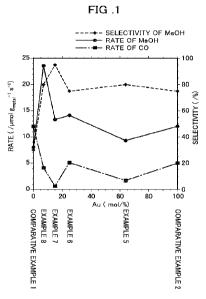
[Methanol selectivity and methanol production rate]
Carbon dioxide reduction reactions were performed using
the carbon dioxide reduction catalysts of Examples 5, 6, 7,
and 8 and Comparative Examples 1 and 2. The reactions were
performed under conditions of a reaction pressure of 50 bar
and a reaction temperature of 250 C, and a methanol (Me01-1)
selectivity (%), a methanol production rate (Me0H) and a
carbon monoxide (CO) production rate were measured. Note that,
each of the Me0H production rate and the CO production rate
was calculated as a rate (pmol/s) per unit weight (g) of the
catalyst components supported on the catalyst (metal). The
results are presented in Table 1. In the graph in FIG. 1, a
horizontal axis represents a rate of Au contained in the
catalyst components (% by mole), a left vertical axis
Date Regue/Date Received 2022-10-24
CA 03181054 2022-10-24 -
19
represents Me0H and CO production rates (41mol g metal's 1),
and a right vertical axis represents a methanol selectivity
(%). In FIG. 1, a dashed line represents the Me0H
selectivity(%), a solid line represents the Me0H production
rate, and an alternate long and short dash line reprosents the
CO production rate (the same applies below).
[0042]
As shown in FIG. 1, the carbon dioxide reduction catalysts
of Examples all exhibited a Me0H selectivity and a Me0H
production rate higher than those of Comparative Examples.
Examples having the rate of Au contained in the catalyst
components of 2 to 25 % by mole exhibited an especially high
Me0H selectivity. When the rate of Au contained in the
catalyst components was 7 to 25 % by mole, a further higher
Me0H selectivity was exhibited_
[0043]
(Test under condition of 240 C)
FIG. 2 is a graph showing the results of carbon dioxide
reduction reactions using the carbon dioxide reduction
catalyst of Example 8 under different pressure conditions. A
temperature condition was 240 C. In the graph in FIG. 2, a
horizontal axis represents a pressure condition in a carbon
dioxide reduction reaction (bar), a left vertical axis and a
right vertical axis represent the Me0H and CO production rates
and the Me0H selectivity, respectively, as in FIG. 1. As shown
in FIG. 2, tests were performed under the pressure conditions
Date Regue/Date Received 2022-10-24
CA 03181054 2022-10-24 -
of 5 bar, 10 bar, 20 bar, 40 bar, and 50 bar.
[0044]
As shown in FIG. 2, the carbon dioxide reduction catalyst
of Example also exhibited a high MeOH selectivity under
pressure conditions of SO bar or less, or oven 40 bar or less,
20 bar or less, 10 bar or less, and 5 bar or less.
[0045]
(Test under condition of 50 bar)
FIGs. 3, 4, and 5 are graphs showing the results of carbon
dioxide reduction reactions using the carbon dioxide reduction
catalysts of Example 8 (FIG. 3), Example 5 (FIG. 4), and
Example 9 (FIG. 5), respectively, under different temperature
conditions. The pressure condition was 50 bar in all tests.
In the graphs in FIGs. 3, 4, and 5, a horizontal axis
represents a reaction temperature ( C), a left vertical axis
and a right vertical axis represent the Me0H and CO production
rates and the Me011 selectivity, respectively, as in FIG. I.
[0046]
As shown in FIGs. :3, 4, and 5, the carbon dioxide
reduction catalysts of Examples exhibited a high Me0H
selectivity at a temperature condition of 240 C or less. Among
them, when the temperature condition was 200 C or less or even
180 C or less, a high MeOH selectivity of almost 100% was
exhibited.
[0047]
(Test under condition of 10 bar)
Date Regue/Date Received 2022-10-24
CA 03181054 2022-10-24 21
FIG. 6 is a graph showing the results of carbon dioxide
reduction reactions using the carbon dioxide reduction
catalysts of Example 8 and Comparative Examples 1 to 3 under a
pressure condition of 10 bar and a temperature condition of
240 C. In the graph in FIG. 6, a left vertical axis and a
right vertical axis represent the Me0H and CO production rates
and the Me0H selectivity, respectively, as in FIG. 1.
[0048]
As shown in FIG. 6, the carbon dioxide reduction catalyst
of Example exhibited a higher Me0H selectivity than those of
the carbon dioxide reduction catalysts of Comparative
Examples, that is, a high Me0H selectivity of 80% or more at a
pressure condition of 10 bar.
[0049]
(Test under condit7ion of 50 bar and 240 C)
FIG. 7 is a graph showing the results of carbon dioxide
reduction reactions using the carbon dioxide reduction
catalysts of Example 8 and Comparative Examples 1 to 3 under a
pressure condition of 50 bar and a temperature condition of
240 C. In the graph in FIG. 7, a left vertical axis and a
right vertical axis represent the Me0H and CO production rates
and the McOH selectivity, respectively, as in FIG. 6.
[0050]
(Test under condition of 5 bar and 240 C)
FIG. 8 is a graph showing the results of carbon dioxide
reduction reactions in the same manner as in FIG. 7 under a
Date Regue/Date Received 2022-10-24
CA 03181054 2022-10-24 -
22
pressure condition of 5 bar and a temperature condition of
240'C. In the graph in FIG. 8, a loft vertical axis and a
right vertical axis represent the Me0H and CO production rates
and the Me0H selectivity, respectively, as in FIG. 6.
[0051]
As shown in FIGs. 7 and 8, the carbon dioxide reduction
catalyst of Example exhibited a higher Me0H selectivity than
those of the carbon dioxide reduction catalysts of Comparative
Examples at pressure conditions of 50 bar and 5 bar.
[0052]
(Comparison test of methanol selectivity)
FIG. 9 is a graph showing the results of carbon dioxide
reduction reactions using the carbon dioxide reduction
catalysts of Examples 1 to 3 and Comparative Examples 1 and 2
under a pressure cond*tion of 40 bar and a temperature
condition of 240 C. In the graph in FIG. 9, a vertical axis
represents a Me011 selectivity.
[0053]
As shown in FIG. 9, the carbon dioxide reduction catalysts
of Examples exhibited a higher Me0H selectivity than those of
the carbon dioxide reduction catalysts of Comparative Examples
under a pressure condition of 40 bar and a temperature
condition of 240 C. Among them, the carbon dioxide reduction
catalyst of Example 3 treated at a hydrogen reduction
treatment temperature of 500 C exhibited a high Me0H
selectivity of 80% or more.
Date Regue/Date Received 2022-10-24
CA 03181054 2022-10-24 -
23
[0054)
(Comparison test of methanol selectivity under condition of
240 C)
FIG. 10 is a graph showing the results of carbon dioxide
reduction reactions using the carbon dioxide reduction
catalysts of Examples 4 and 5 under a temperature condition of
240 C and different pressure conditions. In the graph in FIG.
10, a horizontal axis represents a pressure condition in the
carbon dioxide reduction reactions (bar) and a vertical axis
represents a Me0H selectivity (%). In FIG. 8, a solid line
represents the result of the carbon dioxide reduction catalyst
of Example 5 and a dashed line represents the result of the
carbon dioxide reduction catalyst of Example 4.
[0055)
As shown in FTC- 10, the carbon dioxide reduction
catalysts of Examples also exhibited a high Me0H selectivity
under pressure conditions of 50 bar or less. Among them, the
carbon dioxide reduction catalyst of Example 5 treated at a
hydrogen reduction treatment temperature of 500 C exhibited a
high Me0H selectivity even under the pressure condition of 5
bar.
[0056]
[TEN-EDS measurement]
The carbon dioxide reduction catalysts were observed with
transmission electron microscopy (TEN) using a transmission
electron microscope. FIG. 11 is a portion of a TEN image of
Date Regue/Date Received 2022-10-24
CA 03181054 2022-10-24 -
24
the carbon dioxide reduction catalyst of Example 5. FIG. 12 is
a graph of peak intensities of Cu and Au (CuKa, AuKa) measured
in an area enclosed by a frame border in FIG. 11 as measured
by TEM-EDS measurement. In the graph in FIG. 12, a horizontal
axis represents a distance (nm) and a vertical axis represents
a peak intensity. In the graph in FIG. 12, a solid line
represents a peak intensity of Cu and a dashed line represents
a peak intensity of Au.
[0057]
As shown in FIGs. 11 and 12, it is shown that gold (Au)
and copper (Cu) serving as the catalyst components are
supported together in the same small area of a 10 nm square or
less in the carbon dioxide reduction catalyst of Example 5.
Thus, the gold (Au) and the copper (Cu) are expected to form
an alloy.
[0058]
[XRD measurement]
FIG. 13 is a chart showing the results of a crystal
structure analysis with X-ray diffraction (XRD) of the carbon
dioxide reduction catalysts of Examples 1 to 9. An X-ray
diffractometer (MiniFlex, manufactured by Rigaku Corporation)
was used for measurement. As shown in FIG. 13, neither a peak
derived from elemental Au (38.3 ) nor a peak derived from
elemental Cu (43.3 ) was observed in the carbon dioxide
reduction catalysts of Examples 1 to 9. Therefore, the Au and
the Cu are expected to be in a highly dispersed state in the
Date Regue/Date Received 2022-10-24
CA 03181054 2022-10-24 -
carbon dioxide reduction catalyst of Examples 1 to 9. Note
that, the "highly dispersed state", as used herein, means that
the Au and the Cu are present as tiny crystalline particles of
several nanometers or less or amorphous.
[0059]
[Mossbauer spectroscopy]
FIGs. 14 to 17 are charts of the results of 197Au Mossbauer
spectroscopy in the carbon dioxide reduction catalysts of
Examples and Comparative Example. The Mossbauer spectrometry
was performed as follows. A powdered sample was placed into a
sample cell and "'Pt (half-life: 18.6 hours, gamma-ray energy:
77.4 keV) produced by irradiation with neutrons in a nuclear
reactor was used as a gamma-ray source. A temperature at which
the Mossbauer spectrometry was performed ranged from -261 to -
264 C. The spectrometry was performed at Institute for
Integrated Radiation and Nuclear Science, Kyoto University.
FIG. 14 shows a 197Au Mossbauer spectrum of gold foil serving
as a standard material (corresponding to Comparative Example
2) and a peak position PO is Set as a position at which
velocity (mm/s) is 0 in FIGs. 15, 16, and 17. FIG. 15 shows a
197Au Mossbauer spectrum of the carbon dioxide reduction
catalyst of Example 5, FIG. 16 shows a l'Au Mossbauer spectrum
of the carbon dioxide reduction catalyst of Example 8, and
FIG. 17 shows a 197Au Mossbauer spectrum of the carbon dioxide
reduction catalyst of Example 9. An isomer shift from the ""Au
Mossbauer spectrum of the standard material shown in FIG. 14
Date Regue/Date Received 2022-10-24
CA 03181054 2022-10-24 -
26
was determined and peak splitting was performed for FIGs. 15,
16, and 17 to thereby evaluate components of the alloy.
[0060]
For the carbon dioxide reduction catalyst of Example 5
shown in FIG. 15, isomer shifts to P51 (0.33 mm/s, component
area rate: 66.0%, Cu concentration: 8%) and P52 (1.97 mm/s,
component area rate: 34.0%, Cu concentration: 49%) were
observed. The above-mentioned Cu concentrations were converted
from the isomer shifts. This can be interpreted that there are
66% Au atoms with 8% of atoms surrounding a single Au atom
being Cu atoms, and 34% Au atoms with 49% of atoms surrounding
a single Au atom being Cu atoms. Therefore, this shows that Au
is alloyed.
[0061]
For the carbon dioxlde redocton catalyst of Example 8
shown in FIG. 16, an isomer shift to P81 (3.94 mm/s, component
area rate: 100%, Cu concentration: 98.6%) was observed. The
above-mentioned Cu concentration was converted from the isomer
shift. This can be interpreted that there are 100% Au atoms
with 98.6% of atoms surrounding a single Au atom being Cu
atoms. Therefore, this shows that Au is alloyed.
[0062]
For the carbon dioxide reduction catalyst of Example 9
shown in FIG. 17, isomer shifts to P91 (3.63 mm/s, component
area rate: 96.4%, Cu concentration: 91%) and P92(0.99 mm/s,
component area rate: 3.6%, Cu concentration: 25%) were
Date Regue/Date Received 2022-10-24
CA 03181054 2022-10-24 -
27
observed. The above-mentioned Cu concentrations were converted
from the isomer shifts. This can be interpreted that there arc
96.4% Au atoms with 91% of atoms surrounding a single Au atom
being Cu atoms, and 3.6% Au atoms with 25% of atoms
surrounding a single Au atom being Cu atoms. Therefore, this
shows that Au is alloyed.
[0063]
[XAFS measurement]
FIGs. 18 to 21 are charts showing the results of X-ray
absorption fine structure (XASF) analysis when the carbon
dioxide reduction catalyst of Example 9 was subjected to the
hydrogen reduction treatment. FIGs. 18 and 19 show the
analysis results at an AuL3-edge and FIGs. 20 and 21 show the
analysis results at an CuK-edge. The XAFS analysis was
performed as follows. The analysis was performed at the large
synchrotron radiation facility SPring-8, Beamline TT for
industrial applications (31,14B2) (Hyogo Prefecture, Japan). A
Si (311) surface for the AuL2-edge and a Si (111) surface for
the CuK-edge were used as analyzing crystals. The AuL3-edge
and the CuK-edge were measured by a transmission method. A
cell having a diameter of about 10 mm was packed with a sample
sandwiched between filter papers and set in a quartz cell for
in-situ measurement. After measurement at room temperature,
the measurement was performed while 10% by volume H2/He (20
mL/min) was circulated and a temperature was raised from room
temperature to 500 C at 5 C/min. After a certain period of
Date Regue/Date Received 2022-10-24
CA 03181054 2022-10-24 -
28
time had elapsed since the temperature reached 500 C, the cell
was cooled to room temperature and measured again. An analysis
software Athena in Ifeffit was used for spectral analysis.
[0064]
FIG. 18 shows XASF spectra at the AuL3-edgc of the carbon
dioxide reduction catalyst of Example 9 before and after the
hydrogen reduction treatment, and gold foil (Au), gold oxide
(A1.120), and an AuCu alloy (Au7Cu93) for comparison. ID FIG.
18, a horizontal axis represents energy (eV) and a vertical
axis represents normalized absorption (a.u.) (common in FIGs.
19 to 21). As shown in FIG. 18, it was observed that the
carbon dioxide reduction catalyst of Example 9 showed a peak
in the proximity of the gold oxide (Au203) before the hydrogen
reduction treatment, but showed a peak in the proximity of the
AuCu alloy (Au7Cu93) after the hydrogen reduction treatment
(500 C). This suggests that Au and Cu torm an alloy by the
hydrogen reduction treatment in the carbon dioxide reduction
catalyst of Example 9.
[0065]
FIG. 19 shows XASF spectra at the AuL3-edge of the carbon
dioxide reduction catalyst of Example 9 at the predetermined
temperature before, during, and after the hydrogen reduction
treatment, and gold foil (Au) and gold oxide (Au203) for
comparison. As shown in FIG. 19, for the carbon dioxide
reduction catalyst of Example 9, it was observed that a peak
at a position corresponding to the gold oxide (Au203) began to
Date Regue/Date Received 2022-10-24
CA 03181054 2022-10-24 -
29
decrease at a temperature condition of 105 C or less, and most
of the peak at the position corresponding to gold oxide (Au203)
disappeared and was shifted to a position in the proximity to
the gold foil (Au) at a temperature condition 150 C or more.
This confirmed that Au was reduced by the hydrogen reduction
treatment at a temperature condition of 400 C or less in the
carbon dioxide reduction catalyst of Example 9.
[0066]
FIG. 20 shows XASF spectra at a GuK-edge of the carbon
dioxide reduction catalyst of Example 9 before and after the
hydrogen reduction treatment, and an AuCu alloy (Au7Cu93),
copper foil (Cu), and copper oxide NII:CuO and I:Cu20) for
comparison. As shown in FIG. 20, it was observed that the
carbon dioxide reduction catalyst of Example 9 showed a peak
in the proximity of the copper oxide (TT:CuO) before the
hydrogen reduction treatment, that is, Cu was present as
divalent copper. On the other hand, it was observed that the
carbon dioxide reduction catalyst of Example 9 showed a peak
in the proximity of the AuCu alloy (AulCu93) after the
hydrogen reduction treatment (500 C). This suggests that Au
and Cu form an alloy by the hydrogen reduction treatment in
the hydrogen reduction catalyst of Example 9.
[0067]
FIG. 21 shows XASF spectra at a CuK-edge of the carbon
dioxide reduction catalyst of Example 9 at the predetermined
temperature before, during, and after the hydrogen reduction
Date Regue/Date Received 2022-10-24
CA 03181054 2022-10-24 -
treatment. In FIG. 21, TI to T5 represent predetermined
retention times after reaching 500 C, Ti represents 5 min, T2
represents 10 min, T3 represents 15 min, T4 represents 20 min,
and T5 represents 25 min. As shown in FIG. 21, it was observed
that the carbon dioxide reduction catalyst of Example 9 showed
a change in that a peak in the proximity of an absorption edge
decreased from the spectrum similar to that of copper oxide
(II:CuO) in Figure 20 at a temperature condition 405 C or
less. Furthermore, it was observed that most of a peak at a
position corresponding to Cu(II) disappeared and shifted to a
position in the proximity of that of copper foil (Cu) about 10
minutes after reaching 500 C. This confirmed that Cu was
reduced by the hydrogen reduction treatment at a temperature
condition of 400 C or less in the carbon dioxide reduction
catalyst of Example 9.
[0068]
[HAADF-STEM measurement]
The carbon dioxide reduction catalysts of Examples 5, 8,
and 9 were measured with high-angle annular dark field
scanning transmission electron microscopy (HAADF-STEM). Each
of the catalysts of Examples 5, 8, and 9 was dispersed in
ethanol, added to a Ni grid for TEN measurement dropwise, and
dried to prepare a sample for measurement. Titan G2 60-300
(manufactured by EEL company) was used for the measurement.
[0069]
FIGs. 22, 23, and 24 show the HAADF-STEM results of the
Date Regue/Date Received 2022-10-24
CA 03181054 2022-10-24 -
31
carbon dioxide reduction catalysts of Examples 5, 8, and 9,
respectively. In the carbon dioxide reduction catalysts of the
above-mentioned Examples, a nanoparticle supported on a ZnO
support shown in FIGs. 22 to 24 were observed to be composed
of high-brightness atoms and low-brightness atoms. In the
HAADF-STEM measurement, an atom with a higher atomic number
has a higher brightness. Therefore, the high-brightness atoms
in Figs. 22 to 24 represent Au atoms, and the low-brightness
atoms represent Cu atoms. The above results show that Au and
Cu form a single nanoparticle on the ZnO support. This
suggests that the gold (Au) and the copper (Cu) form an alloy.
[0070]
[Durability test]
FIGs. 25 and 26 are graphs showing the results of
continuous carbon dioxide reduction reactions using the carbon
dioxide reduction catalyst of Example 8 under a pressure
condition of SO bar and a temperature condition of 240 C.
Changes in Me0H and CO production rates and a 1V1e0H selectivity
Over time were measured and the results are shown in the
graphs in FIGs. 25 and 26. In the graphs in FIGs. 25 and 26, a
horizontal axis represents time (min) and a right vertical
axis represents a Me0H selectivity. A left vertical axis in
FIG. 25 represents Me0H and CO production rates (/pmol gAu-is-1)
relative to an amount of Au contained in catalyst components
(q). A left vertical axis in FIG. 26 represents Me0H and CO
production rates (/pmol gAu-ls-1) relative to a total amount of
Date Regue/Date Received 2022-10-24
CA 03181054 2022-10-24 -
32
Au and Cu contained in catalyst components (g) .
[0071]
As shown in FIGs. 25 and 26, the carbon dioxide reduction
catalyst according to Example exhibited high stability, and no
deterioration in activity or methanol selectivity was observed
even when it continuously underwent the carbon dioxide
reduction reaction for 2000 min or more.
Date Regue/Date Received 2022-10-24