Note: Descriptions are shown in the official language in which they were submitted.
WO 2021/245687
PCT/IN2021/050156
A SYSTEM AND A METHOD FOR REDUCING PARTICULATE
POLLUTANTS IN AIR, USING PULSED ELECTROMAGNETIC WAVES
HELD OF INVENTION
IOU The present disclosure relates to the field of reducing
particulate pollutants in
air. In particular, it belongs to the field of use of electromagnetic
radiation for reducing
particulate pollutants in air.
BACKGROUND OF THE INVENTION
[02] Air pollution affects 92% of the world's population and is estimated to
causes 7
million premature deaths annually. It is also estimated that it costs
developing countries
8.5% of their Gross Domestic Product. Poor air quality is a matter of great
concern in
developing countries. Particulate matter has long been recognized as one of
the key
pollutants detrimental to human health (Harrison and Yin, 2000; Leiva, G al,
2013;
Oli,,Tieri and GireliL 2013).
[03] There is compelling evidence of the adverse effects of particulate matter
on
public health at exposure levels as experienced by global urban populations
(Alorld
Health Organization, 2005). A recent survey by the National Clean Air Program
initiative identified 102 noneattainment cities in India, which fail to meet
the National
ambient air quality standards. Con.ventional pollution management strategies
to improve
air quality include promoting green energy efficient fuels as alternatives to
fossil fuels.
Efforts also include the use of green transportation systems, Use of
Electrostatic
precipitators, scrubbers, filters for industrial establishments are mandated
by law and
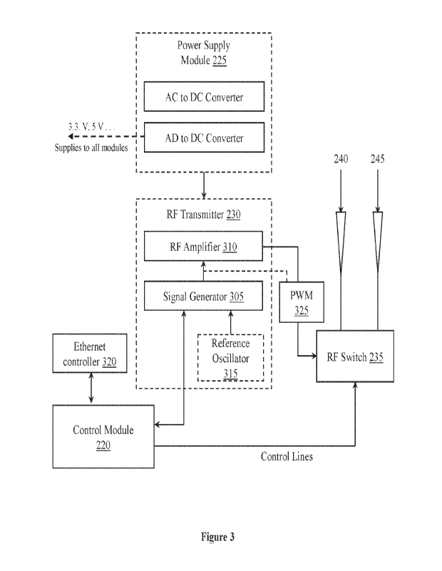
efforts towards improved enforcement of compliance in industries are under
way,
[04] Despite these measures, air pollution continues to increase, Although
there are
several air pollution control devices in the market, most of them are
associated with
high initial capital cost, high operation arid maintenance cost and low area
of coverage.
CA 03181245 2022- 12- 2
WO 2021/245687
PCT/IN2021/050156
105] Conventionally, there are two types of air purifying
technologies available -
active and passive. Active air purifiers release negatively charged ions into
the air,
causing pollutants to stick to surfaces, while passive air purification units
use air fitters
to remove pollutants.
1061 The most common types of air purifier technologies are
listed below:
= HEPA Technology
= Activated Carbon Technology
= Electrostatic precipitator
= Negative Ion
= Ozone
107] The main features of each of these technologies along
with their major
advantages and disadvantages are shown in the table in Figure 1.
1081 High Efficiency Particulate Air (HEPA) technology uses filters that must
meet
predefined standards. Large particles are unable to pass through the openings
of the
fibers and are caught. The smaller particles get caught by one of three
mechanisms ¨
interception, impaction and diffusion. HEPA air purifiers are the most
effective at
trapping airborne particles.
1091 Activated Carbon Technology uses a form of carbon that has been processed
to
make it extremely porous and to give it a very large surface area for
absorption and
adsorption. Air purifiers with activated carbon filters are particularly
helpful to people
with Multiple Chemical Sensitivity (MCS) because they absorb formaldehyde,
which is
found in carpet, wood paneling, and furniture upholstery. Activated Carbon air
filters
help in reducing the contamination of the air. They do, however, have a low
efficiency
in removing allergens and airborne particles. They also act in closed spaces
and with
limited range.
2
CA 03181245 2022- 12- 2
WO 2021/245687
PCT/IN2021/050156
[010] Electrostatic precipitator also called electrostatic air cleaner is a
device that uses
a high-intensity electric field to remove certain impurities - solid particles
and liquid
droplets from air or gases in smokestacks and flues. Originally configured for
recovery
of valuable industrial process materials, electrostatic precipitators are used
for air
pollution control. Dust particles, once collected, are removed from the
collector plates
periodically. Electrostatic precipitators are efficient in removing
particulate pollutants
and can be used to collect dry as well as wet pollutants at low operating
costs in
industrial smokestacks. However, electrostatic precipitators have a high
initial capital
cost. They require large spaces for installation and once installed they are
not flexible in
operation.
[011] Negative Ion air purifiers use chemical injections to clean the air. An
ion is a
particle with either a positive or negative charge. Negative ions are simply
atoms that
have gained an electron. They attract airborne particles such as pollen and
dust, until the
newly formed particles are too heavy to remain suspended in air. This causes
the
particle to drop and settle, leaving the air cleaner.
[012] Ozone air purifiers produce ozone (03) which reacts with strong odors
and
airborne chemicals. Although it is believed that these devices are safe and
effective in
controlling indoor air pollution, governments have not approved these devices,
because
it may cause breathing difficulties in some people and may also be
carcinogenic.
Further, Ozone itself is considered to be a pollutant.
[013] All these device and methods are useful in a limited area or in enclosed
spaces.
SUMMARY OF THE INVENTION
[014] This summary is provided to introduce a selection of concepts in a
simple
manner that is further described in the detailed description of the
disclosure. This
summary is not intended to identify key or essential inventive concepts of the
subject
matter nor is it intended for determining the scope of the disclosure.
3
CA 03181245 2022- 12- 2
WO 2021/245687
PCT/IN2021/050156
[015] Thus, there is no method or system available that can reduce particulate
pollutants across a large area. Thus, there has been a long felt need for a
method of
purifying air of particulate matter and gaseous pollutants and an air purifier
device that
clears the ambient air of suspended particles or particulate pollutants.
[016] This disclosure discloses a method of purifying air that can overcome at
least
one of the disadvantages of the state of the art methods in purifying air of
particulate
matter and also some gaseous pollutants,
[017] This disclosure discloses an air purifier system that can overcome at
least one of
the disadvantages of the state of the art systems in purifying air of
particulate matter
contained in it and also some gaseous pollutants.
10181 The disclosed method comprises radiating pulsed electromagnetic
radiation in
the radiofrequency band for accelerating the agglomeration of particulate
matter in the
air such that they settle down as aggregates and thereby reduce the percentage
of
particulate matter in the air, The interaction of suspended particulate matter
of size less
than 10 um with the radio waves causes them to agglomerate, become heavier and
hence their precipitation is speeded up. Thus the suspended particulate matter
settles
down faster than they would otherwise do. The clearance or transport of
particles from
the air to the solid surfaces in the absence of precipitation occurs by the
natural
phenomenon of Dry deposition. Further, the method is effective in operation
over a
large area surrounding the system - up to a radius of 1 to 3 kilometers.
[019] Also disclosed is a device for radiating pulsed electromagnetic
radiation in the
radiofrequency band, with a predefined nominal frequency for promoting the
agglomeration of particulate matter in the air such that they settle down as a
precipitate
and thereby reduce the percentage of particulate matter in the air.
[020] This disclosure further discloses a system, comprising the disclosed
device
whereby the purification of air can be managed effectively.
4
CA 03181245 2022- 12- 2
WO 2021/245687
PCT/IN2021/050156
[021] The disclosed system is configured for radiating radio waves, preferably
in the
frequency range of 800 :MHz to 5 CHU in a predefined pulsed manner.
Essentially the
disclosed system comprises the device comprising a radiofrequency oscillator
tuned to
or otherwise configured for oscillating at the predefined frequency. The
signal is then
suitably power amplified arid using a suitable switch the amplified output is
routed to a
radiating antenna. In one embodiment there are two antennae, one polarizing
omnidirectional antenna and a directional antenna. The omnidirectional antenna
is used
for all round coverage to induce agglomeration of particulate matter all
around the
system. The directional antenna is used when the source of the pollution is
known and
the emission of particulate matter is to be controlled at the source, to
prevent it from
spreading to a larger area. The power amplified signal is pulsed with
variations in echo
train length (5 to 200), duty cycle (10% to 80%), and pulse power amplitude
(20% to
100% of max power).
[022] Further to clarify the advantages and features of the present
disclosure, a more
particular description of the disclosure will be rendered by reference to
specific
embodiments thereof, which is illustrated in the appended figures. It is to be
appreciated
that these figures depict only typical embodiments of the disclosure and are
therefore
not to be considered limiting of its scope. The disclosed method, device, and
system
will be described and explained with additional specificity and detail with
the
accompanying figures.
BRIEF DESCRIPTION OF FIGURES
[023] The disclosure will be described and explained with additional
specificity and
detail with the accompanying figures in which:
[024] Figure 1 shows a table comparing the prior art methods for preventing or
reducing ambient or/and indoor pollution;
5
CA 03181245 2022- 12- 2
WO 2021/245687
PCT/IN2021/050156
[025] Figure 2 is a block diagram of a system for reducing particulate
pollutants in air
in accordance with an embodiment of the present disclosure; and
10261 Figure 3 is a detailed block diagram of the device 215 for generating
and
radiating the pulsed electromagnetic waves for reducing the particulate
pollutants in air
in accordance with an embodiment of the present disclosure.
10271 Further, persons skilled in the art to which this disclosure belongs
will
appreciate that elements in the figures are illustrated for simplicity and may
not have
been necessarily drawn to scale. Furthermore, in terms of the construction of
the joining
ring and one or more components of the bearing assembly may have been
represented in
the figures by conventional symbols, and the figures may show only those
specific
details that are pertinent to understanding the embodiments of the present
disclosure so
as not to obscure the figures with details that will be readily apparent to
those of
ordinary skill in the art having benefit of the description herein_
DETAILED DESCRIPTION
[028] For the purpose of promoting an understanding of the principles of the
disclosure, reference will now be made to the embodiment illustrated in the
figures and
specific language will be used to describe them. It will nevertheless be
understood that
no limitation of the scope of the disclosure is thereby intended. Such
alterations and
further modifications to the disclosure, and such further applications of the
principles of
the disclosure as described herein being contemplated as would normally occur
to one
skilled in the art to which the disclosure relates are deemed to be a part of
this
disclosure.
10291 It will be understood by those skilled in the art that the foregoing
general
description and the following detailed description are exemplary and
explanatory of the
disclosure and are not intended to be restrictive thereof.
6
CA 03181245 2022- 12- 2
WO 2021/245687
PCT/IN2021/050156
[030] In the present disclosure, relational terms such as first and second,
and the like,
may be used to distinguish one entity from the other, without necessarily
implying any
actual relationship or order between such entities.
[031] The terms "comprises", "comprising", or any other variations thereof,
are
intended to cover a non-exclusive inclusion, such that a process or method
that
comprises a list of steps does not include only those steps but may include
other steps
not expressly listed or inherent to such a process or a method. Similarly, one
or more
elements or structures or components preceded by "comprises._ a" does not,
without
more constraints, preclude the existence of other elements, other structures,
other
components, additional devices, additional elements, additional structures, or
additional
components. Appearances of the phrase "in an embodiment", "in another
embodiment"
and similar language throughout this specification may, but do not
necessarily, all refer
to the same embodiment.
[032] Unless otherwise defined, all technical and scientific terms used herein
have the
same meaning as commonly understood by one of ordinary skill in the art to
which this
disclosure belongs. The components, methods, and examples provided herein are
illustrative only and not intended to be limiting.
[033] While aspects of proposed disclosure may be implemented in any number of
different computing systems, environments, and/or configurations, the
embodiments are
described in the context of the following exemplary environment.
[034] Figure 2 is a block diagram of a system for reducing particulate
pollutants in air
in accordance with an embodiment of the present disclosure. A.s shown, the
system 200
comprises a server 205, a communication network 210 and a device for
generating
pulsed electromagnetic waves 215 (hereinafter referred to as device 215),
wherein the
device 215 comprises a control module 220, a power supply' module 225, an RIF
transmitter 230, an RF switch 235 and two antennae 240 and 245.
7
CA 03181245 2022- 12- 2
WO 2021/245687
PCT/IN2021/050156
[035] The server 205 may include, for example, a computer server or a network
of
computers or a virtual server comprising one or more processors, associated
processing
modules, interfaces and storage devices. As shown, the server 205 is
communicatively
connected to the device 215 through the communication network 210. In one
embodiment of the present disclosure, the server 205 is configured for
communicating
operating instructions to the device 215 for operating the device 215
depending on one
or more factors. The one or more factors may include, but not limited to, a
geographical
location of the device 215, a current atmospheric condition, that is, the
ambient
temperature and relative humidity or both, at the geographical location of the
device
215, an estimate of the pollution characteristics at the geographical location
and one or
more inputs provided by a user of the device 215. In other words, the server
205 enables
remote operation of the device 215 for reducing the air pollution. Further,
the server 205
is configured for monitoring the state of health of the device 215. It is to
be noted that
the server 205 may be communicatively connected with a plurality of devices,
each
being of the type similar to the device 215, for controlling the air pollution
using various
devices at the same or different geographical locations and for monitoring the
health of
the plurality of devices.
[036] The communication network 210 may be a wireless network or a wired
network
or a combination thereof. Wireless network may include long range wireless
radio,
wireless personal area network (WPAN), wireless local area network (WLAN),
mobile
data communications such as 3G-, 4G or any other similar technologies. The
communication network 210 may be implemented as one of the different types of
networks, such as intranet, local area network (LAN), wide area network (WAN),
the
internet, and the like. The communication network 210 may either be a
dedicated
network or a shared network. The shared network represents an association of
the
different types of networks that use a variety of protocols, for example,
Hypertext
'Transfer Protocol (IITTP), Transmission Control Protocol/Internet Protocol
iTf..7P/IP),
Wireless Application Protocol (WAP), and the like_ Further the communication
network
210 may include a variety of network devices, including routers, bridges,
servers,
modems, computing, devices, storage devices, and the like, in one
iniplementation, the
8
CA 03181245 2022- 12- 2
WO 2021/245687
PCT/IN2021/050156
cimnunication network 210 is the i ntern et which enables communication
between the
server 205 and the device 215 which generates the pulsed electromagnetic waves
215.
[037] in one embodiment of the present disclosure, the device 215 is
configured for
generating pulsed electromagnetic waves in the frequency range of 2.4 to 2.5
Gliz
(ISM Band) and the generated pulsed electromagnetic waves are radiated using a
unidirectional antenna or an omnidirectional antenna or both. The
electromagnetic
waves are pulsed with variations in echo train length, duty cycle, and pulse
amplitude
according to the local conditions, that is, the ambient temperature and
relative humidity.
or both of the geographical area,. The radiated pulsed electromagnetic waves
create
dielectric effect under the influence of a spatially non-uniform electric
field. As a result,
the small pollutant particles undergo a net translational motion via the
dielectrophorelic
force, causing their motion to accelerate, and the pollutant particles in the
air settle
down as a result of aggregation of the pollutant particles, thereby reducing
their
concentrations in the air_ The manner in which the pulsed electromagnetic
waves are
generated and radiated for reducing the particulate pollutants in air is
described in detail
further below.
[038] Figure 3 is a detailed block diagram of the device 215 for generating
and
radiating the pulsed electromagnetic waves for reducing the particulate
pollutants in air
in accordance with an embodiment of the present disclosure. As shown and
described
with reference to Figure 2, the device 215 comprises the control module 220,
power
supply module 225, the RF transmitter 230, the RE switch 235 and two antennae
240
and 245. Further, in one embodiment of the present disclosure, the RE module
230
comprises a signal generator 305, an RF amplifier 310 and a reference
oscillator 315.
Functions of said modules in generating the pulsed electromagnetic waves are
described
in detail further below.
[039] The control module 220 includes a mierocontroller for controlling the
various
operations of the device 215. In one implementation, the control module 220 is
8-bit
microcontroller operating with an internal clock of 32 MHz (Programmable). The
9
CA 03181245 2022- 12- 2
WO 2021/245687
PCT/IN2021/050156
control module 220 controls an Ethernet controller 320, the signal generator
305 (RF
Synthesizer), the RE Amplifier 310 and the RE switch 235. The communication
between control module 220 (microcontroller) and the Ethernet controller 320
is
through SPI Protocol. One end of the Ethernet controller 320 is connected to
the control
module 220 and the other end is connected to RI 45 Connector. The control
module 220
receives remote control data via communication modem and through the Ethernet
controller 320. in one implementation, the control module 220 and the signal
generator
305 communicate through SPI protocol. In one embodiment of the present
disclosure,
the control module 220 is used to program the signal generator 305 for proper
output
frequency, duty cycle and output power. The output power of the signal
generator 305
may be varied by steps of 3 dB. The Ethernet controller 320 can communicate
with
2G13GrIeTE and Ethernet supported mod.em, there by establishing intern&
access. The
control module 220 ensures remote monitoring as well as control and variation
of the
RE pulse parameters.
[040] The power supply module 225 is mediated through an adapter with AC Input
at
90 ¨ 264 VAC, 50/60 Hz and DC Output at 12 V, 2 A, 24 W. The supply voltages
of all
ICs in the device are either 3.3V or 5V. In one implementation DC to DC
converters or
regulators are used to step down the voltage from adapter into two levels. The
maximum current drawn by each regulator is 1 A. Both the regulators receive 12
V from
the AC to DC adapter. The DC to DC converters converts the DC voltage to 3.3 V
and 5
V. For adequate power dissipation, proper heat sink selection and the copper
area under
the module is in place. Additionally, provided is an EMI filter circuit of DC
to DC
converter to effectively reduce EMI noise for both conducted and radiated test
by
filtering the input voltage. The power supply module 225 supplies DC operating
voltages to all the modules of the device 215.
10411 As described, the device 215 generates the pulsed electromagnetic waves
in the
frequency range of 800 MHz to 5 GHz and the generated pulsed electromagnetic
waves
are radiated using one of the unidirectional antenna and the omnidirectional
antenna. In
particular, the signal generator 305 generates the signal with the desired
frequency from
CA 03181245 2022- 12- 2
WO 2021/245687
PCT/IN2021/050156
a reference input from the reference oscillator 315, the generated signal is
amplified
using the RF amplifier 31.0, the amplified signal is periodically interrupted
for
generating the pulsed signal (pulsed electromagnetic waves), and the pulsed
electromagnetic waves are radiated through one of the antenna 240 and 245,
selected
using the RE switch 235, into the air. The pulsed electromagnetic waves
accelerate the
agglomeration of particulate matter suspended in the air thereby accelerating
the
precipitation of the particulate matter, and thereby reducing the proportion
of particulate
matter suspended in the air. It is to he noted that the pulsed electromagnetic
waves may
be generated in one or more methods. As described, in one implementation, the
signal is
generated using the signal generator 305, the signal is amplified using the RE
amplifier
310, and the amplified signal is interrupted before feeding it to the antenna
for
generating the pulsed signals (pulsed electromagnetic waves). In another
implementation, the signal is generated using the signal generator 305, the
generated
signal is interrupted, before feeding it to the RF amplifier 310 for
generating the pulsed
signal, and the pulsed signal is amplified and fed to the antenna. A pulse
width
modulator 325 for interrupting the signal is shown in. Figure 3. In yet
another
implementation, a pulsed signal is generated using the signal generator 305,
and then
the pulsed signal is power amplified and fed to the antenna. It is to be noted
that the
signal generator 305 and the RE amplifier 310 are digitally controlled to
attain the
required power and the duty cycle. As described, any one of the method may be
implemented for generating the pulsed electromagnetic waves. The pulse width
modulator 325 is shown in Figure 3 for illustrating one of the methods.
[042] Referring back to Figure 3, in one embodiment of the present disclosure,
the
signal generator 305 is configured for generating a signal in the frequency
range of 800
MHz to 5 GHz from a single reference frequency from the reference oscillator
315. That
is, the signal generator 305 receives -RF reference input from the RF
oscillator 315 and
produces an output. The minimum RF output power is -4 dBm and maximum is
+5 dBm. The output frequency is programmable in the RF synthesizer 305 and the
output is fed to the RE amplifier 310.
CA 03181245 2022- 12- 2
WO 2021/245687
PCT/IN2021/050156
[043] As described, the reference oscillator 315 inputs a reference frequency
to the
signal generator 305 for generating signal of 800 MHz to 5 GHz. In one
implementation, 25 MHz temperature compensated crystal oscillator is used for
generating 25 MHz reference signal. In the present case the reference
oscillator 315 is
selected to have the preferred frequency of 25 MHz with a piezo electric or
any other
suitable reference.
[044) In one embodiment of the present disclosure, the RF amplifier 310 is a
variable
gain RF amplifier which receives the signal from the signal generator 305 and
controls
the output power from the signal generator 305. The output of the RF amplifier
310 is
connected to the RE switch 235.
[045] In one embodiment of the present disclosure, the RE switch 235 is used
for
selecting one of an omnidirectional antenna 240 or a directional antenna 245
for
radiating the pulsed electromagnetic radiation into the atmosphere. In a
preferred
embodiment, the RF switch 235 is a digitally controlled single pole double
throw switch
configured for taking input from RF amplifier 310. The output RF1 or RF2 is
selected,
for radiating electromagnetic radiation through an omnidirectional antenna 240
or a
directional antenna 245, through the logic control voltages from control
module 220.
The RF switch 235 provides desired isolation between the two RF paths.
[046) The antennae 240 and 245 are broad range omnidirectional and directional
antennae for radiating pulsed electromagnetic waves into the atmosphere. The
omnidirectional antenna 240 is used for all round coverage to induce
agglomeration of
the particulate matter all around the antenna 240. The directional antenna 245
is used
when the source of the pollution is known and the emission of particulate
matters is to
be controlled at the source, to prevent particulate matters from spreading to
a larger
area. Based on the application, one of the antennae 240 and 245 are selected
through the
RF switch 235 through the control module 220.
12
CA 03181245 2022- 12- 2
WO 2021/245687
PCT/IN2021/050156
Working Mechanism:
[047] The control module 220 of the device 215 controls the RF signal
generator 305,
the RF switch 235 and digital step attenuator in the variable gain RF
amplifier 310. The
reference oscillator 315 provides the reference frequency required for the RF
signal
generator 305. Based on the reference signal and the control from the control
module
220, the RF signal generator 305 produce an output in four different levels
(between -4
dBm and 5 dBm) at a frequency of 800 MHz to 5 GI-1z (programmable as per the
local
conditions). This RF signal is amplified to levels that can be digitally
controlled using
control module 220 (by controlling attenuation of digital step attenuator) by
the variable
gain RF amplifier 310. The output power of the variable gain RF amplifier 310
drives
the externally connected antennae. The antennae are connected through single
pole
double throw switch 235 which is controlled by the control module 220. Using
internet
access, the device 215 can also be accessed remotely through the server 205
and the
communication network 210 to select the of antenna and pulse modulation
parameters.
[0481 During operation, one of the antennae 240 and 245 radiates the pulsed
electromagnetic waves into the atmosphere. The radiated pulsed electromagnetic
waves
create dielectric effect under the influence of a spatially non-uniform
electric field. As a
result, the small pollutant particles undergo a net translational motion via
the
dielectrophoretic force, causing their motion to accelerate, and the pollutant
particles in
the air settles down as a result of agglomeration of the pollutant particles,
thereby
reducing the air pollution.
[049] The use of pulsed electromagnetic waves in the Wi-Fig frequency range
reduces
the levels of particle pollutants in ambient and indoor air spaces to mitigate
air
pollution. The pulsed radio wave technology reduces particulate pollutants
(PM2.5 and
PM10) by a minimum of 33% and 50 - 60% in most of cases. Certain gaseous
pollutants
(typically as aerosols or secondary particulate pollutants) such as nitrogen
oxides,
Sulphur dioxide, and carbon monoxide are reduced by 20-30% depending on their
initial concentration. Unlike conventional air purifiers which make use of
HEPA filters,
13
CA 03181245 2022- 12- 2
WO 2021/245687
PCT/IN2021/050156
pulsed radio wave technology uses an omnidirectional antenna or a directional
antenna
to generate weak radio waves in a specific pulsed sequence. Because radio
waves are
able to travel over long distances (compared to cell phone signals, Bluetooth,
or Wi-Fi),
the technology is able to work over large distances. The pulsed radio waves
accelerate
the velocity of the small particle pollutants (< 20 microns) and aerosols,
increasing their
clearance through a natural process called dry deposition.
[050] The system and device disclosed in the disclosure for reducing
particulate
pollutants in air, using pulsed electromagnetic waves, doesn't require fans or
filters and
hence sustainable with low recurring cost in comparison with convention air
purifier or
air pollution control systems. Further, the device covers larger area as the
pulsed radio
waves cover an average of 1000-2000 m radius, which is at least ten times more
than
the conventional purifiers. Furthermore, the device utilizes minimum power of
30W,
and doesn't produce noise.
[051] While specific language has been used to describe the disclosure, any
limitations
arising on account of the same are not intended. As would be apparent to a
person
skilled in the art, various working modifications may be made to the method in
order to
implement the inventive concept as taught herein.
[052] The figures and the foregoing description give examples of embodiments.
Those
skilled in the art will appreciate that one or more of the described elements
may well be
combined into a single functional element. Alternatively, certain elements may
be split
into multiple functional elements. Elements from one embodiment may be added
to
another embodiment. For example, orders of processes described herein may be
changed and are not limited to the manner described herein. Moreover, the
actions of
any flow diagram need not be implemented in the order shown; nor do all of the
acts
necessarily need to be performed. Also, those acts that are not dependent on
other acts
may be performed in parallel with the other acts. The scope of embodiments is
by no
means limited by these specific examples. Numerous variations, whether
explicitly
given in the specification or not, such as differences in structure,
dimension, and use of
14
CA 03181245 2022- 12- 2
WO 2021/245687
PCT/IN2021/050156
material, are possible. The scope of embodiments is at least as broad as given
by the
following claims.
15
CA 03181245 2022- 12- 2