Note: Descriptions are shown in the official language in which they were submitted.
CA 03182366 2022-11-04
WO 2021/224778 PCT/IB2021/053711
METHOD, APPARATUS, AND SYSTEM OF A FIBRILLATED NANOCELLULOSE
MATERIAL
Technical Field
[0001] Aspects of the invention generally relate to renewal and recyclable
material.
More particularly, embodiments of the invention relate to fibrillated
cellulose
materials made for consumer products.
Background
[0002] Increasing concerns over the environmental crisis¨plastic waste
pollution¨has
triggered extensive investigations into sustainable and renewable materials.
In the
effort to circumvent petroleum derivative polymers, a naturally occurring
biopolymer,
plant-based¨cellulose fibers offers alternatives to the material research
community.
Cellulose fibers are gaining their attention due to the ubiquitous source,
sustainable,
renewable, and more importantly, it affords the end product with 100%
biodegradability in nature.
[0003] However, many existing biodegradable products based on cellulose fibers
fail to
live up to the expectation. For example, the cost of producing these cellulose
fibrous products is not economically conducive for mass production. In
addition,
due to the need for water resistance, oil resistance or non-stick property,
many of the
cellulose fibrous products rely heavily on synthetic chemical compositions to
achieve
these properties or effects. For example, many existing products require a
coat of
fluorocarbon to be applied on the surface that come in contact with food or
beverage
items. Moreover, some of these fluorocarbon-based chemicals, such as
perfluorooctanoic acid (PFOA or C8), may cause long-term negative health and
environmental effects.
[0004] In addition, current practices do not create two layers or layers of
fibrillated
cellulose materials. Rather, prior practices merely attempt to produce one
layer
from a cellulose pulp solution.
Summary
[0005] Embodiments of the invention overcome the shortcomings of prior
technologies
by infusing nanocellulose in a fibrillated form to enhance the properties of
cellulose
1
CA 03182366 2022-11-04
WO 2021/224778 PCT/IB2021/053711
pulp. These properties may include, for example, the mechanical and barrier
properties, i.e., tensile strength, liquid, and gas impermeability such as
oxygen,
carbon dioxide, and oil, may be improved substantially.
[0006] Another embodiment of the invention further provide a fibrillated
cellulose
composite material that include layers or mixtures of fibrillated cellulose to
create
properties of being a strength-enhancing agent, an oligomer, carboxylic acid,
plasticizer, an antimicrobial agent, water repellant, and/or a transparent
composite.
The composite material further may be generally free from chemical additives
to
enhance the above properties. In yet another embodiment, the composite
material
may further include a base substrate such as pulp and another layer such as
fibrillated cellulose.
Brief Description of Drawings
[0007] Persons of ordinary skill in the art may appreciate that elements in
the figures
are illustrated for simplicity and clarity so not all connections and options
have been
shown. For example, common but well-understood elements that are useful or
necessary in a commercially feasible embodiment may often not be depicted in
order
to facilitate a less obstructed view of these various embodiments of the
present
disclosure. It may be further appreciated that certain actions and/or steps
may be
described or depicted in a particular order of occurrence while those skilled
in the art
may understand that such specificity with respect to sequence is not actually
required. It may also be understood that the terms and expressions used herein
may
be defined with respect to their corresponding respective areas of inquiry and
study
except where specific meanings have otherwise been set forth herein.
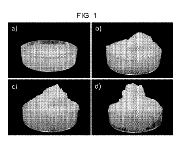
[0008] FIGS. 1A through 1D illustrate a material of the cellulose fibers
aqueous
suspension according to one embodiment.
[0009] FIG. 2 is a scanning electron microscope (SEM) image for a material
with
fibrillated cellulose (3 wt. %) according to one embodiment.
[0010] FIG. 3A to 3D are scanning electron microscope (SEM) images for semi-
processed cellulose fibers where a-b are SEM images for Y-cellulose fibers and
c-d
for B- cellulose fibers according to one embodiment.
[0011] FIGS. 4A to 4D are SEM images for mechanically ground semi-processed
fibers, where a-b are Y-cellulose fibers, and c-d for B-cellulose fibers
according to
2
CA 03182366 2022-11-04
WO 2021/224778 PCT/IB2021/053711
one embodiment.
[0012] FIG. 5 illustrates images of containers made of fibrillated cellulose
L28b, L29b,
L30b, and Y were able to hold oil for 10 days according to one embodiment.
[0013] FIG. 6A are images showing food items with boiling water in a material
for about
minutes according to one embodiment.
[0014] FIG. 6B are images showing food items with boiling water and under
microwave
being heated at 800 W for 2 minutes according to one embodiment.
[0015] FIG. 7 is another SEM image of a material for a structure of
fibrillated cellulose
used in food container according to one embodiment.
[0016] FIG. 8 is a flow diagram of a method for generating a material
according to one
embodiment.
[0017] FIG. 9 illustrates three images showing a film according to one
embodiment.
[0018] FIGS. 10A to 13 illustrate apparatuses according to one embodiment.
[0019] FIGS. 14A to 14D illustrate exemplary end products produced by aspects
of the
embodiments.
Detailed Description
[0020] Embodiments may now be described more fully with reference to the
accompanying drawings, which form a part hereof, and which show, by way of
illustration, specific exemplary embodiments which may be practiced. These
illustrations and exemplary embodiments may be presented with the
understanding
that the present disclosure is an exemplification of the principles of one or
more
embodiments and may not be intended to limit any one of the embodiments
illustrated. Embodiments may be embodied in many different forms and should
not
be construed as limited to the embodiments set forth herein; rather, these
embodiments are provided so that this disclosure may be thorough and complete,
and may fully convey the scope of embodiments to those skilled in the art. The
following detailed description may, therefore, not to be taken in a limiting
sense.
[0021] Embodiments of the invention include a material, such as a Green
Composite
Material TM (GCMTm), that may comprise fibrillated cellulose as a core
material
without any material. In one embodiment, the composite material may include
pulp
and fibrillated cellulose. In another embodiment, the composite material may
be
generally free from chemical additives or agents. In yet another embodiment,
the
3
CA 03182366 2022-11-04
WO 2021/224778 PCT/IB2021/053711
composite material may be independently derived plant fibers. In one
embodiment,
the chemical additives or agents may be naturally based or non-toxic. In
another
embodiment, the chemical additives or agents may be created by laboratories.
In
some embodiments, these plant fibers may be derived from bagasse, bamboo,
abaca, sisal, hemp, flax, hop, jute, kenaf, palm, coir, corn, cotton, wood,
and any
combination thereof. In yet other embodiments, the plant fibers may be pre-
processed or semi-processed cellulose. In other embodiments, a green composite
material with fibrillated cellulose may be obtained by processing plant fibers
through
a refining process, such as a high-pressure homogenizer or refiner. In further
embodiments, a composite material with fibrillated cellulose obtained via
bacterial
strains (without the cellulose producing microorganism). In alternative
embodiments,
a material with fibrillated cellulose may be obtained from a marine source.
[0022] In one embodiment, the shape and size of the cellulose may depend on
the
source of origin of the fiber or a combination of fibers and the process of
making it.
Nonetheless, fibrillated cellulose generally has a diameter and a length, as
described
below. The fibrillated cellulose, in one embodiment, may have a diameter of
about
1-5000 nanometer (nm). In yet another embodiment, the fibrillated cellulose
may
have a diameter of about 5-150 nm or from about 100-1000nm. In yet another
embodiment, the fibrillated cellulose may have a diameter of about 5000-
10000nm.
[0023] In yet a further embodiment, the material may have enhanced properties
that
heighten, enhance, or improve various properties without toxic chemical
additives or
agents. In another embodiment, the material having various properties that are
suitable to carry food or liquid items that is generally free from chemical
additives or
agents. For example, as shown in prior art, various toxic chemical additives
or
agents have added to materials during manufacturing process or coated thereon
that
provide a desirable tensile strength, either dry or wet, enhanced oil barrier,
gas
and/or liquid impermeability. Aspects of the invention, instead of with the
various
toxic chemical additives or agents added to the material, include a composite
material with the fibrillated cellulose that is generally free from these
additives or
agents.
[0024] For example, the fibrillated cellulose may have a length of about 0.1 ¨
1000
micrometers, about 10¨ 500 micrometers, about 1 ¨25 micrometers, or about 0.2
¨
100 micrometers. In some embodiments, a material with fibrillated cellulose of
4
CA 03182366 2022-11-04
WO 2021/224778 PCT/IB2021/053711
different diameters, such as with a weight ratio of 1:100. In another
embodiment,
the fibrillated cellulose may be with a weight ratio of 1:50. In a further
embodiment,
the material with mixed fibrillated cellulose may afford the advantages such
as
improved tensile strength, either dry or wet, enhanced oil barrier, gas and/or
liquid
impermeability, and cost savings.
[0025] In some embodiments, a material with fibrillated cellulose may possess
a
property of an oxygen transmission rate of about 8000 cm3 m-224 h-1 or less.
In
another embodiment, the oxygen transmission rate of about 5000 cm3 m-2 24 h-1
or
less. In yet another embodiment, the oxygen transmission rate of about 1000
cm3
m-2 24 h-1 or less.
[0026] Furthermore, in yet some embodiment, the material may possess a
property of a
water vapor transmission rate of about 3000 g m-2 24 h-1 or less. Moreover,
for
another embodiment, the water vapor transmission rate may be about 1500 g m-2
24
h-lor less.
[0027] In some embodiments, a material may possess a property of a dry tensile
strength of about 30 MPa or higher. In another embodiment, the dry tensile
strength may be about 70 MPa. In yet another embodiment, the dry tensile
strength
may be about 100 MPa or higher. In some embodiments, the material may possess
a property of a dry tensile modulus of about 4 GPa or higher. In another
embodiment, the dry tensile modulus of about 6 GPa or higher.
[0028] In some embodiments, the material may possess a property of a dry
tensile
index of about 45 Nm g-1 or higher. In another embodiment, the property may be
about 80 Nm g-1 or higher.
[0029] In some embodiments, the material may possess a property of a wet
tensile
strength of about 5 MPa or higher. In another embodiment, the wet tensile
strength
may be about 20 MPa or higher.
[0030] In some embodiments, the material may possess a property of a wet
tensile
modulus of about 0.4 MPa or higher. In another embodiment, the wet tensile
modulus may be about 1.0 MPa or higher.
[0031] In some embodiments, the material may possess a property of a wet
tensile
index of about 5 Nm g-1 or higher. In another embodiment, the wet tensile
index
may be about 20 Nm g-1 or higher.
[0032] In an alternative embodiment, the material may include an adhesive
agent to
CA 03182366 2022-11-04
WO 2021/224778 PCT/IB2021/053711
enhance dry and/or wet strength. In one embodiment, the adhesive agent may
include polymers. In other embodiments, the adhesive agent may include metal
salts. In another embodiment, the adhesive agent may include oligomers. In yet
other embodiment, the adhesive agent may include a carboxylic acid. In yet an
alternative embodiment, the adhesive agent may include a plasticizer. In some
embodiments, the weight ratio of fibrillated cellulose to the adhesive agent
in the
present invention may be about 33:1 to 1:1.
[0033] For example, the polymers may include polyester, gelatin, polylactic
acid, chitin,
sodium alginate, thermoplastic starch, polyethylene, chitosan, chitin glucan,
polyvinyl
alcohol, or polypropylene. In one embodiment, the polymers may include in
chemical additives that may be applied to the composite materials of aspects
of the
invention. For example, the chemical additives may be embedded in the material
itself or may be sprayed or coated thereon.
[0034] In yet another embodiments, the adhesive agent may include metal salts.
For
example, the metal salts may include potassium zirconium carbonate, potassium
aluminum sulphate, calcium carbonate, and calcium phosphate. In some
embodiments, the weight ratio of fibrillated cellulose to the adhesive agent
in the
present invention may be about 33:1 to 1:1.
[0035] In another embodiment, the adhesive agent may include oligomers. In one
example, the oligomers may include oligonucleotide, oligopeptide, and
polyethylene
glycol. In some embodiments, the weight ratio of fibrillated cellulose to the
adhesive
agent in the present invention may be about 33:1 to 1:1.
[0036] In yet other embodiment, the adhesive agent may include a carboxylic
acid. For
example, the carboxylic acid may include citric acid, adipic acid, and
glutaric acid. In
some embodiments, the weight ratio of fibrillated cellulose to the adhesive
agent in
the present invention may be about 33:1 to 1:1.
[0037] In embodiment, the adhesive agent with the plasticizer may reduce a
brittleness
and gas permeability of the adhered composite. In some embodiments, the
plasticizer may include polyol. In one embodiment, the polyol may comprise
glycerol.
In one embodiment, the polyol may comprise sorbitol. In one embodiment, the
polyol
may comprise pentaerythritol. In some embodiments, the polyol may comprise
polyethylene glycol. In some embodiments, the weight ratio of plasticizer to
the
composite material to an adhesive agent is about 5: 33: 1 to about 1: 1: 1.
6
CA 03182366 2022-11-04
WO 2021/224778
PCT/IB2021/053711
[0038] In another embodiment, the plasticizer may comprise branched
polysaccharide,
wax, fatty acid, fat and oil.
[0039] Aspects of the invention may further include a water repellent agent as
a
chemical additive to repel gas and/or liquid state water. In some embodiments,
the
water repellent agent comprises an animal-based wax, an animal-based oil or an
animal-based fat. In one embodiments, the water repellent agent comprises a
petroleum-derived wax or a petroleum-based wax. In other embodiments, the
water
repellent agent comprises a plant-based wax, a plant-based oil or a plant-
based fat.
[0040] In some embodiments, an animal-based water repellent may comprise
beeswax, shellac and whale oil.
[0041] In some embodiments, a petroleum-based wax water repellent may comprise
paraffin wax, paraffin oil and mineral oil.
[0042] In some embodiments, a plant-based water repellent may comprise
carnauba
wax, soy oil, palm oil, palm wax, carnauba wax and coconut oil.
[0043] In some embodiments, a water repelling agent may comprise adhesive
agent
such as potassium zirconium carbonate, potassium aluminum sulphate, calcium
carbonate and calcium phosphate.
[0044] In a further embodiment, the material may comprise fibrillated
cellulose further
optionally may include an antimicrobial agent. In some embodiments, an
antimicrobial agent may comprise tea polyphenol. In some embodiments, an
antimicrobial agent may comprise pyrithione salts, parabens, paraben salts,
quaternary ammonium salts, imidazolium, benzoic acid sorbic acid and potassium
sorbate.
[0045] Moreover, another embodiment of the invention may include a material
having
fibrillated cellulose further optionally comprises a transparent composite to
increase
the transmission of light with wavelength from about 300 to 800nm. In some
embodiments, a material may comprise branched polysaccharides. In some
embodiments, the weight ratio of the material to transparent composite ranges
differently, which may depend on the transparency required, e.g., about 99: 1
to
about 1:99.
[0046] In some embodiments, branched polysaccharides may comprise starch,
dextran, xantham gum, and galactomannan.
[0047] In some embodiments, a dextran may comprise agarose, pullulan, and
curdan.
7
CA 03182366 2022-11-04
WO 2021/224778 PCT/IB2021/053711
[0048] In some aspects, provided herein is the manufacture of products made by
the
material disclosed herein, and readily forms into designated shape, e.g.,
either 2
dimensional or 3-dimensional. For example, the two-dimensional example may be
a planar sheet where the planar sheet may be used to be decomposed for forming
end products. In another example, the material may be in a solution that may
be
ready for forming end products. In yet another embodiment, the three-
dimensional
example may be end products.
[0049] In one aspect, the In some embodiments, the end product may include
containers for digestible or edible items, such as those shown in FIGS. 5 to
FIG. 7.
For example, the end products that embody the materials as described in this
application may include food containers or packages. Using it as an example
and
not as a limitation, the food containers or packages may include airplane or
airline
meal containers, disposable cups, ready-to-eat food containers, capsules, ice
cream
carton or containers, and chocolate containers. In some embodiments, a product
may comprise instant food containers that may further contain spices, e.g.,
instant
cup noodles, instant soup, or the like. In such example, for a consumer to
digest or
consume the digestible or edible items contained in the container embodying
aspects of the invention, the container may be subjected to water or liquid at
high
temperature, such as about 100 degrees Celsius.
[0050] In another embodiment, for products that may be used one an airplane
meal
and beverage containers. Currently, the airplane meal containers are made of
various forms of plastic for properties of lightweight, rigidity, oil
resistance, etc. In
addition, existing plastic containers may be subjected to heating via an oven.
The
heating may release carcinogenic substance from the plastic container to the
digestible or edible items. As such, such effects are not desirable.
Embodiments
of the invention, along with the properties described above, may exhibit
properties
that are water resistant, high heat tolerance, oil resistant, etc., without
releasing
carcinogenic substance.
[0051] In another embodiment, the capsule example may be a capsule for
machines for
hot beverage. For example, the capsule may be contain coffee, tea, herbs, or
other
drinks. For example, the capsule may be a disposable capsule. In another
example, the capsule may be a disposable coffee bag or pouch. In such an
example,
the electrical beverage machine may deposit or inject water at high
temperature or
8
CA 03182366 2022-11-04
WO 2021/224778 PCT/IB2021/053711
high pressure to the capsule so that the beverage making process may start and
that
the coffee may drip out of the capsule or pouch to a consumer's cup. As the
capsule or pouch comprises the biodegradable and sustainable materials having
one
or more properties as described above, the capsule or pouch may be easily
recycled
without creating burden to the environment.
[0052] In one embodiment, the capsule may have a sidewall with a thickness of
about
500 micron. In one embodiment, the capsule may include a top or a lid having a
thickness of about 500 micron. In yet another embodiment, the capsule may
include a bottom thickness of about 300 micron. In yet a further embodiment,
the
capsule may be formed/created in one pass from the former (to be discussed
below)
and that the thickness of a top, a sidewall and a bottom with different
thickness.
[0053] In some embodiments, a product may include a filter to separate,
whether
permanently, semi-impermeable, or lightly impermeable to particles or
molecules in
fluid. For example, the product may include a face mask or filter membrane
with
solid-liquid separation, liquid-liquid separation, or gas-liquid separation
effects, etc.
[0054] In some embodiments, a product may comprise cosmetic or skincare
container
products, medical products, e.g., powder case, palette, protective glass, or
medical-
grade disposals. In some embodiments, a product may comprise part of medical
device, automobile, electronic device, and construction material (as
reinforcement
material).
[0055] Overall, in one embodiment, containers embodying materials of the
invention
may be in a form of containers, planar sheets, trays, plates, reels, boards,
or films.
In such an embodiment, a width or length of the material may range from about
0.01
mm to 10000 mm or above. In one embodiment, the width or length may range
from about 0.01 mm-1000 mm. In the embodiment where the films may be a thin-
layered film with a thickness of about 0.01 ¨ 3.0 mm. In one embodiment, the
thickness may be about 0.02 ¨ 0.20 mm. In yet other embodiments, the product
may comprise a food package containing oil to water weight ratio of about
100:1 to
about 1:100.
[0056] In another embodiment, aspects of the invention may provide a process
of
manufacturing, generating, or creating the material comprising fibrillated
cellulose
having properties of the above.
Example 1
9
CA 03182366 2022-11-04
WO 2021/224778 PCT/IB2021/053711
[0057] In addition to the material provided above, aspects of the invention
may include
a cellulose fibrillation process or method.
[0058] Referring now to FIG. 8, a flow diagram may illustrate a method for
creating
such material according to one embodiment. In one embodiment, the examples
shown below are generally free from toxic chemical additives to improve
mechanical
properties of the composite material. For example, a cellulose paper board
(about
3.0 wt. %) was torn into pieces such as A4 sized paper. The shredded pieces is
thrown into a pulping machine (not shown in FIG. 8). The pulping process may
take
about 20 minutes. Next, for example, a refiner 802 may be used to begin the
process. For example, the refiner 802 may be a homogenizer, a grinder, a
chemical
refinement chamber/bath, a combination of a mechanical and chemical fiber
refinement device, or the like. In one embodiment, in the example of a
grinder, the
refiner 802 may include a two grindstones facing each other. The separations
or
distances between the two grindstones may be adjusted as a function of the
desirable end products. In another embodiment, surface grooves or patterns may
be adjusted as a function of the desirable end products. As such, a pulp
suspension 806 is then fed into the refiner, optionally for about 1 - 10
passes. In
other instances, the pulp suspension 806 may be fed into a refiner (not
shown), e.g.,
colloid mill, double disk grinder, to refine further the cellulose pulp before
entering the
refiner 802.
[0059] In one embodiment, FIGS. la to ld show the condition of fibrillated
cellulose
with increasing numbers of passes. For example, FIG. la may represent a
cellulose fibers aqueous suspension with 0 cycle or pass. In other words, the
content of the pulp suspension 806 as shown in FIG. la where the pulp forms no
fibrillation to achieve the qualities and properties of aspects of the
invention.
[0060] In one embodiment, FIG. lb may illustrate a post-refinement 808 where
the pulp
suspension 806 has passed the refiner 802 after 1 pass. For example, the post-
refinement 808 may now include fibrillated cellulose fibers aqueous
suspension. In
another example, FIG. lc illustrates an image of a post-refinement 808 that
has
passed the refiner 802 after 2 passes or 2 cycles. In one example, the
fibrillated
cellulose fibers in the post-refinement 808 is finer than that of what's shown
in FIG.
lb. FIG. ld may illustrate an image of a post-refinement 808 after 3
cycles/passes.
In such an embodiment, the post-refinement 808 may include even finer
fibrillated
CA 03182366 2022-11-04
WO 2021/224778 PCT/IB2021/053711
cellulose fibers than that in FIG. 1c.
[0061] In one embodiment, different cellulose starting concentrations have
been
evaluated and tested. For example, the post-refinement 808 may include
fibrillated
cellulose fibers and water with concentrations of fibrillated cellulose at
about 2.5
wt.% of cellulose (and 97.5% water), about 3.0 wt.% of cellulose, about 3.6
wt.% of
cellulose, and about 4.0 wt.% of cellulose were tested and used.
[0062] For example, insufficient refining was found for the cellulose
concentration of
about 2.5 wt.% of cellulose, and the properties were not tested. In other
words,
fibrillated cellulose fibers concentration with about 2.5 wt.% or even regular
pulp
suspension solution would be insufficient for achieving properties of aspects
of the
invention. The fibrillated cellulose with the post-refinement 808 with about
3.0 wt.%,
about 3.6 wt.%, and about 4.0 wt.% are termed herein as L028, L029, and L030,
respectively, in FIG. 5.
[0063] In one embodiment, various properties of the fibrillated cellulose were
tested.
For example, in Table 1, the properties of mechanical, water vapor and gas
permeability are shown.
Table 1
Approxi mat Oxygen
DRY DRY WET WET Water vapor
Fibrillate e Cellulose transmission rate,
tensile tensile tensile tensile transmission
pulp OTR (cm3/ m224h)
strengt index strengt index rate, WVTR
cellulose concentrati
on h (MPa) (Nm/g) h (MPa) (Nm/g) (g/m2.h) 5 % RH 50%
RH
L028 3.00% 90 5 105 610 2 10 3 920 0.1
0.010
L029 3.60% 90 5 100 4 8 2.00 6 2 925 0.1
0.1
L030 4.00% 80 6 95 15 8 2 7 2 1015 1
0.500
[0064] In one embodiment, FIG. 2 may illustrate a SEM image of fibrillated
cellulose at
about 3 wt. % concentration.
Example 2
[0065] In one example, instead of using direct pulp solution to derive at the
post-
refinement 808, in Example 1 above, a semi-processed cellulose fibers may be
obtained from a market source. As such, the semi-processed cellulose fibers
(e.g.,
about 3 wt. %) is fed into a colloid mill and grind for about 1 minute.
Optionally, the
fibrillated cellulose fibers may further be processed in the refiner 802.
11
CA 03182366 2022-11-04
WO 2021/224778 PCT/IB2021/053711
[0066] In one example, FIG. 3 may illustrate an SEM image for semi-processed
fibers
after colloid milling for 1 minute. For example, Table 2 shows the properties
of
different fibrillated cellulose from different source.
Table 2
Wet OTR
Fibrillated Dry tensiletensile (cc/m2.24h) VVVTR
strength
cellulose strength (g/m2.24h)
(MPa) (MPa) 5% RH 50% RH
5Z09
6.99 1.91 0.019 0.011 864.72
7.75
30.57
2.01 0.29 - 1075.68
3.64
38.97
3.43 0.20 115.44 92.98 1094.4
2.29
[0067] For example, FIG. 3 may illustrate where a-b are SEM images for Y-
cellulose
fibers in Table 2 and c-d are SEM images for B- cellulose fibers.
[0068] In another embodiment, FIG. 4 shows SEM images for semi-processed
fibers
after mechanically ground for 1 cycle/pass. For example, wherein FIG. 4 a-b
are for
Y-cellulose fibers, and FIG. 4 c-d are for B-cellulose fibers.
[0069] In one aspect, a mixer 804 may provide a suspension of pulp 806 of
cellulose
pulp in water comprises a mixture of cellulose pulp in water, wherein the
cellulose to
water weight ratio is about 0.01 to 100. In another embodiment, the weight
ratio
may be about 0.03 to 0.10. In some embodiments, the post-refinement 808 from
the refiner 802 may be kept in the event that it may be used to be grinded
again by
the refiner 802. For example, as described above, the number of passes that
the
post-refinement 808 goes through the refiner 802 may be from 1 ¨ 100. In
another
embodiment, the number of passes or cycles may be further limited to 1 ¨ 10.
[0070] In another embodiment, a weight ratio of the fibrillated cellulose to
water and/or
the number of passes through the refiner 802 may be a function of the end
products'
desirable properties. For example, if the end product requires a low water
vapor
transmission, and a low oxygen transmission, then the post-refinement 808 may
be
with a weight ratio of cellulose to water closer to about 0.03-0.04 3-4% (as
12
CA 03182366 2022-11-04
WO 2021/224778 PCT/IB2021/053711
demonstrated by L28b ¨ L30b) and/or the number of passes may increase. In yet
another embodiment, the relative low water vapor transmission, and relative
low
oxygen transmission may indicate high shelf life while the relative high water
vapor
transmission and relative high oxygen transmission may indicate lower shelf
life.
[0071] In one embodiment, the post-refinement 808 may be processed by a former
810. For example, the former 810 may generate an intermediate 818 based on the
post-refinement 808 to a desirable material with the fibrillated cellulose.
For
example, the intermediate 818 may be at a ratio by weight of fibrillated
cellulose to
liquid (e.g., water) of about 0.001 to 99. In another embodiment, the ratio
may be
from about 0.001 to 0.10. In one embodiment, the former 810 may include a mesh
or
fibrous network. For example, the former 810 may include a negative pressure
and/or positive pressure or any combination thereof. In one embodiment, the
former 810 may apply pressure to separate the fibrillated cellulose in the
post-
refinement 808 from liquid to form the intermediate 818. Due to the
fibrillated
nature of the fibrillated cellulose fibers and through the process of the
refiner 802,
the fibers with different lengths may form the intermediate 818, as shown by
the
various SEM images in FIGS. 2-4 and 7.
[0072] In another embodiment, a base layer 812 may be used in conjunction with
the
post-refinement 808 to form the intermediate 818. In one embodiment, the GCM
of
aspects of the invention may include a composite material having a substrate
layer
of pulp (e.g., the base layer 812) and a fibrillated cellulose layer (e.g.,
from the post-
refinement 808). For example, the former 810 may subject the base layer 812 to
a
mesh, a mold, or a frame to form a construct for the intermediate 818. For
example, the base layer 812 may first be in a form of a solution or slush of
water and
pulp material. The slush may be in a tank and the mesh may be in the tank as
well.
Through a negative pressure such as a vacuum, water from the tank may be
removed or reduced so the based layer 812 is formed on the mesh.
[0073] Subsequently, in one embodiment, the former 810 may include a sprayer
or an
applicator for spraying or applying the post-refinement 808 to the base layer
812 to
form the intermediate 818. With the different sizes of fibers between the base
layer
812 and the post-refinement 808, the post-refinement 808 is infused with the
base
layer 812. In one embodiment, the post-refinement 808 may be applied or
sprayed
on a surface of the intermediate 818 that carries edible items. For example,
13
CA 03182366 2022-11-04
WO 2021/224778 PCT/IB2021/053711
suppose an end product is a bowl, the post-refinement 808 may be applied or
sprayed onto an interior surface of the end product.
[0074] In one embodiment, the intermediate 818 may exhibit patterns of the
mesh or
the fibrous network, as shown in 502 or 504, on an exterior surface thereof.
[0075] In yet another embodiment, the former 810 may spread the intermediate
818 on
a flat surface for drying or forming by natural process.
[0076] In another embodiment, a dryer 814 may further be provided to dry or
dehumidify the intermediate 818. In one embodiment, the dryer 814 may provide
a
drying condition of 30 Celcius to 200 Celcius. In another embodiment, the
dryer
814 may include a heated surface, such as an infra-red heating. In another
embodiment, microwave heating or air heating may be used without departing
from
the spirit and scope of the embodiments. In yet another embodiment, the dryer
814
may also be aided by negative pressure and/or positive pressure.
Example 3
[0077] In one example of the end products that may embody aspects of the
invention, a
cellulose based bowl is successfully produced by adopting combinations of
materials
and methods described previously. In one embodiment, the functionality of the
cellulose based food container, in this example, may be used to prove filling
typical
cooking oil into the container, as shown in FIG. 5. In this example, the
cooking oil
with the cellulose-based food container may be heated by microwave at 800W for
4
minutes and observed for 10 days, which is shown in FIG. 5. In such
illustration,
the container in FIG. 5 may represent ones made of fibrillated cellulose L28b,
L29b,
L30b, and Y. In one embodiment, each of the ones in FIG. 5 may be able to hold
oil
for about 10 days.
[0078] In another embodiment, another set of testing was also carried out by
filling
instant noodle (after it is cooked after hot water is added) into a container
em boding
the composite material according to one embodiment. The observations were
recorded on the second day. FIG. 6A shows an example of a fibrillated
cellulose
structure in a container, such as a food container. For example, FIG. 6A
illustrates
a series of images of a fibrillated cellulose filled with boiling water and
let it stand for
about 5 minutes.
[0079] In another embodiment, FIG. 6B illustrates a series of images of the
fibrillated
cellulose filled with boiling water and microwave heated at 800 W for about 2
14
CA 03182366 2022-11-04
WO 2021/224778 PCT/IB2021/053711
minutes.
[0080] FIG. 7 is another image showing a SEM image for a structure of
fibrillated
cellulose in food container in FIGS. 6A and 6B according to one embodiment.
Example 4
[0081] Referring now to FIGS. 9a through 9c, images illustrate a film
according to
example 4 of an embodiment.
[0082] In one embodiment, a composite material according to aspects of the
invention
may be in a transparent composite film based on fibrillated cellulose. In one
example, the film may be produced by dissolving the fibrillated cellulose and
pullulan
powder in water to produce solutions containing about 1 wt.% of solute,
separately.
In the pullulan powder dissolution, the powder may be progressively added
thereto,
and the solution may be heated via microwave at power of 800W for 1 minute. In
one embodiment, this process may repeat for about 4-5 times until a clear
solution is
formed.
[0083] In one embodiment, to produce a composite film, the fibrillated
cellulose, such
as the post-refinement 808, to pullulan may be with a ratio of about 1:1, For
example, about 250 g of the post-refinement 808 (e.g., the fibrillated
cellulose of
about 1%) may be mixed with about 250 g of pullulan solution to produce a
solution
with about 0.5% solute. Then, about 100 g of the mixed solution was poured
onto a
hydrophobic surface, e.g., silicone surface and allowed to dry at room
temperature.
[0084] In another embodiment, a fibrillated cellulose to a pullulan with a
ratio of 2:1,
250 g of the post-refinement (e.g., the fibrillated cellulose of about 2%) may
be
mixed with about 250 g of pullulan solution to produce a solution with about
1%
solute. Then, about 100 g of the mixed solution was poured onto a hydrophobic
surface, e.g., silicone surface and allowed to dry at 50 C and 12 hours.
[0085] As illustrated, FIGS. 9a through 9c may illustrate images of cellulose
based film
where fibrillated cellulose to pullulan with a ratio of a.) 0:1, b.) 1:1, and
c.) 2:1.
[0086] In one embodiment, the addition of pullulan may enhance the film
forming
process to smooth the film's surface, where film made of fibrillated cellulose
(e.g.,
the post-refinement 808), herein termed as L41b below, is highly wrinkled.
Whereas
the other films with pullulan provide smoother and even surface. In one
embodiment, the film of the composite material with the fibrillated cellulose
and
pullulan may be generally free from uneven surface.
CA 03182366 2022-11-04
WO 2021/224778
PCT/IB2021/053711
[0087] In yet another embodiment, mechanical properties of transparent
composite
film were shown below, where fibrillated cellulose is denoted as L41b, and
pullulan is
represented as B.
[0088] Table 3 Properties of fibrillated cellulose films with the addition of
pullulan.
Sample 100B L41b:B L41b:B L41b:B L41b:B
1:1 1:1 2:1 1:1, 6% WSA
Weight (g) 0.75 1 1g 1
Thickness (mm) 0.025 0.035 0.06 0.05
0.06
............................... , ................ , ........... , ..........
Dry Tensile Strength - 33.54 42.07 50.055
60.9 5.17
(MPa) 5.49 11.13 6.98
, ................................................. , ........... , ..........
Dry Young's - 1176.01 6062.55
13481.95
8203.87
Modulus (MPa) + +
13055.80
588.09
1469.73 886.95
Dry Tensile Index - 38.95 39.94
51.54 8.07 54.73
6.67
(Nm/g) 5.58 6.23
Wet Tensile
N.A N.A N.A
4.64 1.11
Strength (MPa)
Wet Young's
185.97
N.A N.A N.A
Modulus (MPa)
228.53
Wet Tensile Index
N.A N.A N.A
3.98 0.81
(Nm/g)
OTR 5% RH 0.055
(cm3i m2
500/0 RH
24h) 0.137
WVTR (g/m2h) 103.16 76.57 67.09 69.01
Example 5
[0089] Fibrillated cellulose with water repellant
[0090] In one embodiment, aspects of the invention may include fibrillated
cellulose
with water repellant. In one example, the mixture may include a correct ratio
of
cellulose and a water repellant, and blended for 3 minutes using a mechanical
blender. The mixture may further be diluted to 4000 mL and pour onto the
former
810. In one aspect, the former 810 may apply negative and/or positive pressure
to
produce a wet preform with a dryness of 25-35%. The mechanical and barrier
properties of the mixture may be shown in Table 4.
16
CA 03182366 2022-11-04
WO 2021/224778 PCT/IB2021/053711
[0091] Table 4 illustrates properties of fibrillated cellulose films with
different water
repellant.
Sample Name M055+10% M055+20% M055+10%
Carnauba wax Carnauba wax Canola oil
Weight (gr) 5g GCM+0.5g wax 5g GCM+1g wax 5g GCM+0.5g
oil
Thickness (mm) 0.156 0.168 0.154
Tensile Strength (MPa) 78.96 26.68 76.215 14.75 86.47 4.8
Young's Modulus (MPa) 7611.49 788.28 7485.75 332.20 8045.41
742.03
Tensile Index (Nm/g) 88.85 27.80 86.69 21.71 96.34 2.72
Wet tensile Strength 11.14 2.48 15.10 2.29 9.03 1.48
(MPa)
Wet Young's Modulus 1258.27 203.63 1720.10 407.88 949.51
61.29
(MPa)
Wet Tensile Index (Nm/g) 12.10 2.27 16.82 2.81 9.69 1.52
GTR 0% 75.88
(cm3/m2=24h=atm) RH
50% 4701.98
RH
OTR 5% 0.047 0.104 0.009
(cm3/m2=24h) RH
50% 0.044 0.022 0.040
RH
WVTR (g/m2.24h) 614.4 411.6 905.52
[0092] In addition, the above embodiments may be made using the devices shown
in
FIGS. 10A to 13. From the simplified diagram in Figure 10A, the 1000 component
may be regarded as a container. After the pulp is loaded, the paper fiber may
be
received by the 1001 from the water tank containing the pulp using its vacuum
principle. For example, 1001 may include a fiber catcher. For example, the
fiber joint
may be a mesh, because the paper fibers of the water tank may stay in the mesh
body, and the liquid will pass through the mesh. The vacuum principle includes
first
pumping and discharging the water in the water tank, and then allowing the
vacuum
environment to be tightly received on the 1001 component to make a first
material.
In one embodiment, the component 1001 may be rotated to have the component
17
CA 03182366 2022-11-04
WO 2021/224778 PCT/IB2021/053711
faching upward or downward to enter into the container 1000 to form the final
product. The component 1001 may be roated again (e.g., 180 degrees) so that
any
remaining moisture or water or liquid may be extracted.
[0093] In another embodiment, a component 1004 may be connected to a component
1002, and the component 1004 may move its vacuum suction function up, down,
left,
and right, and the component 1004 may be installed and configured with its
component 1002. In one embodiment, component 1002 may be used to receive the
first material on the element 1001. As shown in FIGS. 10A and 10B, the
components 1002 and 1004 may be moved to the third unit or the water removal
device. Similarly, in one embodiment, the component 1002 may be roated to have
the water removed. In addition, the arrangement of the present invention in
the
components 1000, 1002, 1004, 1006, and 1008 does not require linear
arrangement.
Since the component 1004 may move in multiple directions, 1000, 1006 or 1008
may
be circular, triangular, above, below and other relative positions. In
addition, the
component 1004 may include a robotic arm or device to move. In another
embodiment, the component 1004 may be moved manually, and may be moved to
1006 or 1008 by mechanical, rotating disk, or with rail assistance, either
manually or
with motorized assistance (e.g., such as with robotic arms). In some
embodiments,
the component 1004 may be moved individually or collectively when multiple
components 1004 may be employed.
[0094] In some embodiments, in a singular manufacturing process, such as one
product item or a mold loading process, the second material may be received
through 1002 and 1004. In such an embodiment, the second material is
effectively
added to the first material by the components 1002 and 1004. For example, the
second material may be joined to the first material through the component
1006, and
as in the above example, the first and second materials are closely mixed to
form a
third material. In another embodiment, the third material may show that the
first
material and the second material exhibit different layers.
[0095] In another embodiment, where multiple station configurations are
employed, the
components 1000 and 1001 may receive the first material. The components 1001
and 1006 may receive the second material. As such, such multiple station
configuration may produce two different products. As the components 1002 and
1004 move the materials to the next station, the two different products may be
18
CA 03182366 2022-11-04
WO 2021/224778 PCT/IB2021/053711
produced simultaneously or substantially simultaneously. In such embodiments,
the
time needed for producing different products are greatly reduced and the space
neeed to for the equipment may be reduced as well.
[0096] In some embodiments, the container or workstation storing the second
material
additionally adds a source of heat or heating. For example, the component 1002
or
1004 itself or an additional heating source may perform the function of
holding or
heating the container, so that the second material may be mixed with the first
material or before the second material is mixed with the first material to
about 40 or
more degrees Celsius to obtain the best and most efficient production of the
final
product efficiency. In another embodiment, the heating source may be heated by
means of electric heating, steam, liquid or the like.
[0097] In one embodiment, after the first and second materials are mixed, as
described
above, the components 1002 and 1004 are moved to a component 1008 dewatering
station to perform the steps of water removal or water reduction. For example,
after
mixing the first and second materials for the components 1002 and 1004, the
third
material may be moved from the component 1006 to the component 1008. In
another embodiment, the third material is in a vacuum-sealed state during the
mixing
process of the components 1002, 1004, 1006, and 1008 during the mixing of the
third material, and then the positive pressure function or pressurization
function is
used on the component 1008 to make it load the space for combining the
materials.
As the pressure increases, the moisture or water in the third material is
eliminated,
and the original negative pressure design of 1002 and 1004 will further pump
the
combined material or reduce the dry humidity of the combined material. In some
embodiments, the component 1008 may be rotated.
[0098] Finally, the combination of materials into the shaping stage to make
the final
product.
[0099] In another embodiment, the second material may also directly serve as
the main
body of the third material, as shown in FIG. 10B. For example, after entering
the
second element in FIG. 10B, the second material is not mixed with the first
material.
[0100] The device of the present invention may be an automated device, as
shown in
FIG. 11A, that is, the first unit, the second unit, and the third unit are a
set of
coherent devices.
[0101] In another embodiment of the present invention, as shown in FIGS. 11B,
11C,
19
CA 03182366 2022-11-04
WO 2021/224778 PCT/IB2021/053711
and 11D, the third material may be made detachable and separated with a
combination of components.
[0102] In addition, FIGS. 11A to D show that the component 1004 is moved by a
track,
but those skilled in the related art may easily use other methods to move the
component 1004 without departing from the basic principles of the present
invention,
and the movement does not need to be limited to move in the same plane.
[0103] In addition, embodiments of the present invention also includes a
software
system to operate the apparatus of the present invention, including sensors at
the
components 1000, 1001, 1002, 1004, 1006, 1008, etc. to transmit parameter
information. The software system also may include different interfaces,
whether it is
a centralized interface or may be presented on a mobile device via the
network.
Even as shown in FIGS. 11B to 11D, in different embodiments, separate
components
may have a continuous or separate interface and software to communicate and
operate the operation of the units or components. The software system also may
report notifications and warning functions to provide administrators with
efficient
management of the production process.
[0104] The mold and the transfer mold have a rotational feature in some
embodiments.
For example, the component 1001 (e.g., mold) may include a rotation or flip
acapability via an axis. During the molding process, the mold surface may be
upward or downward into the 1000 slurry container or bucket using vacuum or
absorption mechanism. In one example, the component 1002 that transfer the
component 1001 also may include the rotation function. In one aspect, the
component 1001 may be rotated after the product is transferred, and the water
or
moisture may be discharged by means of vacuum or gravitational force.
[0105] Grouting: When 1001 and 1002 are mated or joined, in one example, a
pouring
cavity may be inside the component 1001, and and may use a pump to feed the
material in the container 1000 into the cavity of the component 1001, and then
the
water therein may be drawn or taken out by vacuum or other forces. Once, the
first
material is completed, the second material may be completed by applying the
component 1006 in the same way. In one example, in using the components 1000
and 1006, the slurry bucket (e.g., container 1000) may be installed at any
position
below or above the equipment.
[0106] FIGS. 12A and B may now illustrate another embodiment of the device,
which is
CA 03182366 2022-11-04
WO 2021/224778 PCT/IB2021/053711
also an extension of of FIGS. 10A-11D. For example, the paper forming process
may
include: 1. decompose the cardboard into pulp through the pulping system. The
pulp
may be mixed with other materials required for the pulp before entering the
forming
system. 2. Use vacuum or suction force as the power to attach the pulp
material to
the surface of the mold, and then use the drainage system on the surface of
the
mold to drain the excess water, so that a thin layer of wet embryo material is
formed
on the surface of the mold. 3. After molding, the surface of the product needs
a lot of
moisture. Natural air drying, hot air, air pressure, mold heating and other
methods
may be used to assist hot pressing to drain the remaining moisture of the
material.
[0107] The above description provides the following molding processes:
[0108] (A) Slurry molding method-the molding method is to use the inside of
the mold
to make a vacuum cavity. Under the action of vacuum, the fibers of the pulp
may be
uniformly layered and attached to the molding net on the surface of the mold,
and
the mold surface faces upward into the pulp In the tank, a large amount of
water will
be taken away by vacuum suction. When the product reaches a certain thickness,
the product mold will leave the pulp tank, and the wet embryo pulp on the
surface of
the mold will be dehydrated.
[0109] (B) Grouting method-the surface of the mold is facing upwards, a pulp
tank will
be made around the mold, the pulp will be connected to the pulp tank by means
of a
pulp pipeline, the pulp will be given the amount of pulp according to the
thickness of
the product, and one will be made inside the mold In the vacuum cavity, the
pulp
fibers may be uniformly layered and attached to the forming net on the surface
of the
mold under the action of vacuum, and a large amount of water will be taken
away by
vacuum suction, which forms a wet embryo on the surface of the mold The pulp
is
then dehydrated.
[0110] (C) Reverse suction molding method-the surface of the mold faces down
into
the pulp tank, and a large amount of water will be taken away by vacuum
suction.
When the product reaches a certain thickness, the product mold will leave the
pulp
tank, and the wet embryo pulp on the surface of the mold will be dehydrated.
[0111] In one aspect, embodiments of the invention effectively combine at
least two
materials, through the characteristics of the fiber itself and fibrillated
cellulose, using
the specific arrangement in the process, the two or more layers are more
closely
combined or bonded.
21
CA 03182366 2022-11-04
WO 2021/224778 PCT/IB2021/053711
[0112] In one example, FIGS. 12A and B illustrate a horizontal, linear or a
substantially
linear system where, 1204, 1204' and 1204" may be fixing units, 1202, 1202',
1202"
may be transferring element, 1201, 1201' are molds or mesh, and 1200 may be
the
first layer of a material; 1206 may be a second material; and 1208 may be a
dehydration or positive press component. The feature of this equipment may be
a
horizontal or a linear system (in terms of flow of end product), a multi-
station system,
or an assembly line, and 1202 or 1201 may be rotated, and 1201' may also be
rotated.
[0113] Or the vertical system as described in FIG. 13. The vertical system
includes
1304 as a fixing unit, 1301 as a mold, 1300 as a first material, 1306 as a
second
material, and 1308 for dehydration, dewatering, positive pressure, hot air,
compression, heating, and other machines. Among them, the 1301 mold may be
designed for rotation.
[0114] In another embodiment, the systems of FIGS. 12A and B and FIG. 13 may
be
partially combined.
[0115] From the above embodiments, the method of forming the container 1 of
the first
material and the container 2 of the second material may include one or more
features:
[0116] In the vertical system, if one wishes to complete the two molding molds
at the
same time, one may cooperate with the rotation action. The molding workstation
may
use the injection + suction or suction + injection. The above rotation actions
may be
used: 1. Motor drive mechanism to rotate the mold , 2. The vertical movement
of the
mold drives the connecting rods, racks or mechanical structure equipment to
rotate.
[0117] In addition, the present invention may further enable the following
combinations
to achieve processes that were not possible in the past:
Linear (through manual,
Former or Single unit or Vertical
robotic arm, assembly line
Forming Station System
or rotation)
material 1+ Seuqnece of Mold
material 2 1 and 2 rotation
A+A
A+B separate
A+C separate or concurrently
B+B separate
22
CA 03182366 2022-11-04
WO 2021/224778 PCT/IB2021/053711
B+A separate
B+C separate or needed
concurrently
C+C
C+A
C+B separate or needed
concurrently
[0118] Therefore, the above table shows that the equipment of the present
invention
may be equipped with multiple (more than one) slurries during the molding
stage,
which may produce different molding processes to fulfill other different
product
requirements:
[0119] Thick material finished products with 2mm or more:
[0120] After the forming station is completed, it may be connected or
transferred to the
1008 dehydration process. The dehydration equipment of this equipment is
equipped
with positive pressure and compression devices, which may accelerate the time
of
pulp drainage and forming, which is beneficial for forming thick products.
[0121] Multilayer transfer stacking molding (including composite materials)
[0122] The use of a linear transfer system or a vertical rotation system may
simultaneously complete the connection of the first layer of material and the
second
layer of material. The 1002 and 1004 transfer products may be used to stack
two or
more or the same materials together to make thick and thin composite
materials.
[0123] Multi-color molding
[0124] The use of a linear transfer system or a vertical rotation system may
simultaneously complete the molding of multi-color materials, and complete the
blister process with different colors of pulp on a single product.
[0125] Dyeing and molding
[0126] In the pulp blister molding process, the pulp dyeing needs to be
replaced with
other colors. It is a very time-consuming task to clean the pipeline. One may
use the
multi-pulp bucket to place the pulp dye in a separate molding bucket. After
the first
layer of material is formed, it may be moved to the second layer of dye to
absorb the
plastic dye, so that the surface of the pulp is attached to the color, and
then
transferred to the drying process. This system may shorten the time for the
replacement of different color dyes without the need Clean the pulping system.
23
CA 03182366 2022-11-04
WO 2021/224778 PCT/IB2021/053711
[0127] Optimization of additives
[0128] The timing of pulp additives in pulp molding is very important. One may
add
them and put them in a separate molding barrel. We may choose appropriate
timing
to add them to increase the ability of the additives to combine with the pulp
fibers.
Independent additives may also reduce The chance of pulp backwater being
contaminated by additives in other systems will improve the quality of the
backwater.
[0129] Multilayer material molding
[0130] With this, the forming process of the first layer material and the
second layer
material may be completed at the same time. The transfer products 1002 and
1004
may be used to stack two or more or the same materials together to make a
composite material.
[0131] In FIG. 14A, special features of elements of the containers may enhance
this
usage. For example, airplane food containers need to be light-weight, durable,
and
reheatable or heatable. In addition, ovens or steamers on board a commercial
airplane may be used to heat the meals. Also, the meal items may be with
sauce,
soup, or other liquids or fluids and some of these meal items are served warm
or hot.
[0132] As such, with the mechanical properties illustrated above, the
containers
embodying elements of aspects of the invention also need to accommodate the
packaging of the containers from the kitchen. Therefore, as shown in FIG. 14A,
aspects of the invention may include a lid for the container and the lid is
also made
of the material illustrated in the present application. In addition, the lid
and the
container may include a locking mechanism that enable safe transportation of
the
containers and the meals. As shown in FIG. 14A, a tongue element in the
container's outer edge at the end of its curved end may enter an opening
created by
an end of the lid. In this embodiment, the end of the lid may include a tip
that may
bend toward the container, thus creating the opening, instead of away from the
container. The tip may include a sufficient length that pushes against the
curved
end of the container so as to allow the tongue element to engage the upper end
of
the opening of the lid. As the material having a tensile strength described
above,
the engagement of the tip and the curved end, as well as the tongue and the
upper
end of the lid is strong to keep the lid intact during transportation and
heating/reheating.
[0133] In another embodiment, as shown in FIG. 14B, the tongue may be inserted
to a
24
CA 03182366 2022-11-04
WO 2021/224778 PCT/IB2021/053711
tight opening by the end of the lid so it is a friction fit between the
container and the
lid.
[0134] In yet another embodiment, the outer surface of the lid and the bottom
of the
container may include complimentary features. For example, as shown in FIG.
14C, the meal containers need to be stackable. To prevent or alleviate
slippage of
the container from a lid underneath, the lid may include a lowered center
portion or a
recess with a contoured or concaved curved edge connecting the lowered center
portion and the surface of the lid. Similarly, the footers of the container
may be
positioned inside the lowered center with each of the footers (e.g., 4) to
engage four
corners of the lowered portion and the contoured/concaved curved edge.
[0135] Moreover, the footers are protruding from the bottom of the container,
as shown
in FIG. 14D. In one embodiment, the footers are configured to create
additional
airflow by creating spaces between the container and the lid in a stacked
position so
that heat or steam may flow between the container and the lid. In one aspect,
such
feature further may maintain the wet tensile strength of the container.
[0136] Overall, aspects of the invention overcome shortcomings of the prior
approaches where there are toxic chemicals (e.g., fluoropolymers and its
derivatives)
are added. Aspects of the invention also overcome the shortcomings of prior
approaches of using pulps as the base layer or layers. It is to be understood
that
pulp fibers are in the 10 to 50 micrometer (pm) range for their diameters.
Whereas
aspects of the invention are finer in size, such as in the range of below 1
pm.
[0137] The above description is illustrative and is not restrictive. Many
variations of
embodiments may become apparent to those skilled in the art upon review of the
disclosure. The scope embodiments should, therefore, be determined not with
reference to the above description, but instead should be determined with
reference
to the pending claims along with their full scope or equivalents.
[0138] One or more features from any embodiment may be combined with one or
more
features of any other embodiment without departing from the scope embodiments.
A
recitation of "a", "an" or "the" is intended to mean "one or more" unless
specifically
indicated to the contrary. Recitation of "and/or" is intended to represent the
most
inclusive sense of the term unless specifically indicated to the contrary.
[0139] While the present disclosure may be embodied in many different forms,
the
drawings and discussion are presented with the understanding that the present
CA 03182366 2022-11-04
WO 2021/224778 PCT/IB2021/053711
disclosure is an exemplification of the principles of one or more inventions
and is not
intended to limit any one embodiments to the embodiments illustrated.
[0140] The present disclosure provides a solution to the long-felt need
described
above. In particular, aspects of the invention overcome challenges of relying
on
existing practices of using chemical formulas to provide enhanced properties
for
cellulose materials.
[0141] Further advantages and modifications of the above described system and
method may readily occur to those skilled in the art.
[0142] The disclosure, in its broader aspects, is therefore not limited to the
specific
details, representative system and methods, and illustrative examples shown
and
described above. Various modifications and variations may be made to the above
specification without departing from the scope or spirit of the present
disclosure, and
it is intended that the present disclosure covers all such modifications and
variations
provided they come within the scope of the following claims and their
equivalents.
26