Note: Descriptions are shown in the official language in which they were submitted.
WIND DETECTION METHOD AND SYSTEM
TECHNICAL FIELD
[0001] The present disclosure relates to methods, systems, and techniques
for wind
detection.
BACKGROUND
[0002] In the context of a physical security system, it can be useful to
be able to
automatically recognize intrusion events that result from an actual or
attempted unauthorized
entry of a person or animal into a monitored area. One problem that can arise
in such a context
is how to distinguish between an actual intrusion event, and false alarms such
as those caused
by wind.
SUMMARY
[0003] According to a first aspect, there is provided a wind detection
method comprising:
measuring a first acoustic signal generated by an acoustic sensor positioned
to be actuated in
response to wind; determining an average value of the first acoustic signal
over a sampling
duration; determining that the average value of the first acoustic signal
satisfies a wind detection
threshold; and after determining that the average value of the first acoustic
signal satisfies a
wind detection threshold, determining that the first acoustic signal was
generated by the wind.
[0004] The acoustic sensor may comprise a first optical fiber comprising
at least one
pair of fiber Bragg gratings (FBGs) tuned to reflect substantially identical
wavelengths.
[0005] Measuring the first acoustic signal may comprise: shining a
reference light pulse
and a sensing light pulse along the first optical fiber, the reference light
pulse being delayed
compared to the sensing light pulse by a predetermined period of time selected
such that the
reference light pulse reflected by a first FBG of the at least one pair of
FBGs interferes with the
sensing light pulse reflected by a second FBG of the at least one pair of FBGs
to form a
combined interference pulse; detecting the light reflected by the at least one
pair of FBGs; and
detecting the combined interference pulse and detecting a phase difference
between the
reflected reference light pulse and the reflected sensing light pulse of the
combined interference
pulse to produce a first acoustic signal measurement.
1
Date Recue/Date Received 2022-12-01
[0006] The first optical fiber may comprise measurement channels
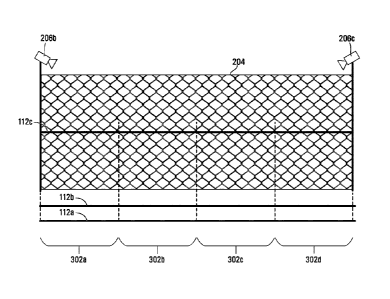
respectively
corresponding to different longitudinal positions along the first optical
fiber; each of the
measurement channels may comprise at least one pair of the FBGs tuned to
reflect substantially
identical wavelengths; and the first acoustic signal may be measured at one of
the measurement
channels.
[0007] The first optical fiber may be mounted on a fence.
[0008] The average value of the first acoustic signal may be a median of
the first acoustic
signal.
[0009] The average value of the first acoustic signal may be the median
of a root mean
square of the first acoustic signal, or a bandpass filtered version of the
root mean square.
[0010] The sampling duration may be at least 15 minutes.
[0011] According to another aspect, there is provided an intrusion
detection method
comprising: detecting a potential intrusion across a fence and into a
monitored area, wherein
the detecting comprises measuring a first acoustic signal generated by an
acoustic sensor
positioned to monitor for intrusions into a monitored area; determining that
the potential intrusion
has a cause other than wind; and in response to determining that the potential
intrusion is has
a cause other than wind, determining that the potential intrusion is an actual
intrusion.
[0012] The method may further comprise orienting a video camera at a
location
corresponding to a source of the actual intrusion event.
[0013] Determining that the potential intrusion event has a cause other
than wind may
comprise determining that an energy acceleration of the first acoustic signal
satisfies an intrusion
energy acceleration threshold.
[0014] Determining that the potential intrusion event has a cause other
than wind may
comprise: determining an average value of the first acoustic signal over a
sampling duration;
and determining that the average value of the first acoustic signal satisfies
a wind detection
threshold.
2
Date Recue/Date Received 2022-12-01
[0015] The average value of the first acoustic signal may be a median of
the first acoustic
signal, and the sampling duration may be at least 15 minutes. The average
value may also be
determined as a median of a bandpass filtered version of the first acoustic
signal.
[0016] The acoustic sensor may comprise a first optical fiber comprising
at least one
pair of fiber Bragg gratings (FBGs) tuned to reflect substantially identical
wavelengths.
[0017] Measuring the first acoustic signal may comprise: shining a
reference light pulse
and a sensing light pulse along the first optical fiber, the reference light
pulse being delayed
compared to the sensing light pulse by a predetermined period of time selected
such that the
reference light pulse reflected by a first FBG of the at least one pair of
FBGs interferes with the
sensing light pulse reflected by a second FBG of the at least one pair of FBGs
to form a
combined interference pulse; detecting the light reflected by the at least one
pair of FBGs; and
detecting the combined interference pulse and detecting a phase difference
between the
reflected reference light pulse and the reflected sensing light pulse of the
combined interference
pulse to produce a first acoustic signal measurement.
[0018] The first optical fiber may comprise measurement channels
respectively
corresponding to different longitudinal positions along the first optical
fiber; each of the
measurement channels may comprise at least one pair of the FBGs tuned to
reflect substantially
identical wavelengths; and the first acoustic signal may be measured at one of
the measurement
channels.
[0019] Determining that the potential intrusion event has a cause other
than wind may
comprise: measuring a second acoustic signal at another of the measurement
channels on the
first optical fiber, or on a measurement channel of a second optical fiber in
acoustic proximity to
the first optical fiber; determining a cross-correlation between the first and
second acoustic
signals; and determining that the cross-correlation satisfies a cross-
correlation threshold.
[0020] Determining that the potential intrusion event has a cause other
than wind may
comprise: measuring a second acoustic signal at another of the measurement
channels on the
first optical fiber, or on a measurement channel of a second optical fiber in
acoustic proximity to
the first optical fiber; and determining that each of the first and second
acoustic signals satisfy
an intrusion threshold.
3
Date Recue/Date Received 2022-12-01
[0021] One of the first and second optical fibers may be mounted on a
fence, and the
other of the first and second optical fibers may be on or buried in ground.
[0022] According to another aspect, there is provided a system
comprising: at least one
optical fiber comprising at least one pair of fiber Bragg gratings (FBGs)
tuned to reflect
substantially identical wavelengths; an optical interrogator optically coupled
to the at least one
optical fiber and configured to perform optical interferometry using the at
least one optical fiber;
and at least one processing device communicatively coupled to the optical
interrogator, wherein
the at least one processing device is configured to perform the methods
described above.
[0023] According to another aspect, there is provided da non-transitory
computer
readable medium having stored thereon computer program code that is executable
by a
processor and that, when executed by the processor, causes the processor to
perform the
methods described above.
[0024] This summary does not necessarily describe the entire scope of all
aspects.
Other aspects, features and advantages will be apparent to those of ordinary
skill in the art upon
review of the following description of specific embodiments.
BRIEF DESCRIPTION OF THE DRAWINGS
[0025] Embodiments of the disclosure will now be described in detail in
conjunction with
the accompanying drawings of which:
[0026] FIG. 1A is a block diagram of an optical interrogation system
including an optical
fiber with fiber Bragg gratings ("FBGs") for reflecting a light pulse, in
accordance with
embodiments of the disclosure;
[0027] FIG. 1B is a schematic diagram that depicts how the FBGs reflect a
light pulse,
in accordance with embodiments of the disclosure;
[0028] FIG. 1C is a schematic diagram that depicts how a light pulse
interacts with
impurities in an optical fiber that results in scattered laser light due to
Rayleigh scattering, which
is used for distributed acoustic sensing ("DAS"), in accordance with
embodiments of the
disclosure;
4
Date Recue/Date Received 2022-12-01
[0029] FIG. 2 is a map of an area that is monitored by an example
intrusion detection
system that comprises the optical interrogation system of FIG. 1A;
[0030] FIG. 3 depicts a segment of a fence partially delineating the area
monitored by
the intrusion detection system;
[0031] FIGS. 4A and 4B depict example acoustic waveforms resulting from a
measurement made along a measurement channel of the intrusion detection
system;
[0032] FIGS. 5, 7A, and 7B depict waveforms of bandpass median root mean
square
(BPRMS) values measured along different measurement channels of the intrusion
detection
system;
[0033] FIG. 6 depicts a method for determining a wind detection
threshold, according to
an example embodiment;
[0034] FIG. 8 depicts a method for wind detection, according to an
example
embodiment;
[0035] FIG. 9 schematically depicts how intrusion events may be
represented in
readings from adjacent measurement channels;
[0036] FIGS. 10A-10C depict various graphs depicting energy acceleration
resulting
from intrusion events and/or wind; and
[0037] FIG. 11 depicts an intrusion detection method, according to an
example
embodiment.
DETAILED DESCRIPTION
[0038] Fiber optic cables are often used as distributed measurement
systems in acoustic
sensing applications. Pressure changes, due to sound waves for example, in the
space
immediately surrounding an optical fiber and that encounter the optical fiber
cause dynamic
strain in the optical fiber. Optical interferometry may be used to detect the
dynamic strain along
a segment of the fiber. Optical interferometry is a technique in which two
separate light pulses,
a sensing pulse and a reference pulse, are generated and interfere with each
other. The sensing
and reference pulses may, for example, be directed along an optical fiber that
comprises fiber
Date Recue/Date Received 2022-12-01
Bragg gratings. The fiber Bragg gratings partially reflect the pulses back
towards an optical
receiver at which an interference pattern is observed.
[0039] The nature of the interference pattern observed at the optical
receiver provides
information on the optical path length the pulses traveled, which in turn
provides information on
parameters such as the strain experienced by the segment of optical fiber
between the fiber
Bragg gratings. Information on the strain then provides information about the
event that caused
the strain.
[0040] Referring now to FIG. 1A, there is shown one embodiment of a
system 100 for
performing interferometry using fiber Bragg gratings ("FBGs"), in accordance
with embodiments
of the disclosure. The system 100 comprises optical fiber 112, an interrogator
106 optically
coupled to the optical fiber 112, and a signal processing device 118 that is
communicative with
the interrogator 106.
[0041] The optical fiber 112 comprises one or more fiber optic strands,
each of which is
made from quartz glass (amorphous SiO2). The fiber optic strands are doped
with various
elements and compounds (including germanium, erbium oxides, and others) to
alter their
refractive indices, although in alternative embodiments the fiber optic
strands may not be doped.
Single mode and multimode optical strands of fiber are commercially available
from, for
example, Corning Optical Fiber. Example optical fibers include ClearCurveTM
fibers (bend
insensitive), 5MF28 series single mode fibers such as SMF-28 ULL fibers or SMF-
28e fibers,
and I nfiniCore series multimode fibers.
[0042] The interrogator 106 generates the sensing and reference pulses
and outputs
the reference pulse after the sensing pulse. The pulses are transmitted along
optical fiber 112
that comprises a first pair of FBGs. The first pair of FBGs comprises first
and second FBGs
114a,b (generally, "FBGs 114"). The first and second FBGs 114a,b are separated
by a certain
segment 116 of the optical fiber 112 ("fiber segment 116"). The optical length
of the fiber
segment 116 varies in response to dynamic strain that the fiber segment 116
experiences.
[0043] The light pulses have a wavelength identical or very close to the
center
wavelength of the FBGs 114, which is the wavelength of light the FBGs 114 are
designed to
partially reflect; for example, typical FBGs 114 are tuned to reflect light in
the 1,000 to 2,000 nm
wavelength range. The sensing and reference pulses are accordingly each
partially reflected
6
Date Recue/Date Received 2022-12-01
by the FBGs 114a, b and return to the interrogator 106. The delay between
transmission of the
sensing and reference pulses is such that the reference pulse that reflects
off the first FBG 114a
(hereinafter the "reflected reference pulse") arrives at the optical receiver
103 simultaneously
with the sensing pulse that reflects off the second FBG 114b (hereinafter the
"reflected sensing
pulse"), which permits optical interference to occur.
[0044] While FIG. 1A shows only the one pair of FBGs 114a,b, in
alternative
embodiments (not depicted) any number of FBGs 114 may be on the fiber 112, and
time division
multiplexing (TDM) (and, optionally, wavelength division multiplexing (WDM))
may be used to
simultaneously obtain measurements from them. If two or more pairs of FBGs 114
are used,
any one of the pairs may be tuned to reflect a different center wavelength
than any other of the
pairs. Alternatively, a group of multiple FBGs 114 may be tuned to reflect a
different center
wavelength to another group of multiple FBGs 114, and there may be any number
of groups of
multiple FBGs extending along the optical fiber 112 with each group of FBGs
114 tuned to reflect
a different center wavelength. In these example embodiments where different
pairs or group of
FBGs 114 are tuned to reflect different center wavelengths to other pairs or
groups of FBGs
114, WDM may be used in order to transmit and to receive light from the
different pairs or groups
of FBGs 114, effectively extending the number of FBG pairs or groups that can
be used in series
along the optical fiber 112 by reducing the effect of optical loss that
otherwise would have
resulted from light reflecting from the FBGs 114 located on the fiber 112
nearer to the
interrogator 106. When different pairs of the FBGs 114 are not tuned to
different center
wavelengths, TDM is sufficient.
[0045] The interrogator 106 emits laser light with a wavelength selected
to be identical
or sufficiently near the center wavelength of the FBGs 114, and each of the
FBGs 114 partially
reflects the light back towards the interrogator 106. The timing of the
successively transmitted
light pulses is such that the light pulses reflected by the first and second
FBGs 114a,b interfere
with each other at the interrogator 106, which records the resulting
interference signal. The
strain that the fiber segment 116 experiences alters the optical path length
between the two
FBGs 114 and thus causes a phase difference to arise between the two
interfering pulses. The
resultant optical power at the optical receiver 103 can be used to determine
this phase
difference. Consequently, the interference signal that the interrogator 106
receives varies with
the strain the fiber segment 116 is experiencing, which allows the
interrogator 106 to estimate
the strain the fiber segment 116 experiences from the received optical power.
The interrogator
7
Date Recue/Date Received 2022-12-01
106 digitizes the phase difference ("output signal") whose magnitude and
frequency vary directly
with the magnitude and frequency of the dynamic strain the fiber segment 116
experiences.
[0046] The signal processing device 118 is communicatively coupled to the
interrogator
106 to receive the output signal. The signal processing device 118 includes a
processor 102
and a non-transitory computer-readable medium 104 that are communicatively
coupled to each
other. An input device 110 and a display 108 interact with the signal
processing device 118.
The computer-readable medium 104 has stored on it program code to cause the
signal
processing device 118 to perform any suitable signal processing methods to the
output signal.
For example, if the fiber segment 116 is laid adjacent a region of interest
that is simultaneously
experiencing vibration at a rate under 20 Hz and acoustics at a rate over 20
Hz, the fiber segment
116 will experience similar strain and the output signal will comprise a
superposition of signals
representative of that vibration and those acoustics. The signal processing
device 118 may
apply to the output signal a low pass filter with a cut-off frequency of 20
Hz, to isolate the vibration
portion of the output signal from the acoustics portion of the output signal.
Analogously, to
isolate the acoustics portion of the output signal from the vibration portion,
the signal processing
device 118 may apply a high-pass filter with a cut-off frequency of 20 Hz. The
signal processing
device 118 may also apply more complex signal processing methods to the output
signal;
example methods include those described in PCT application PCT/CA2012/000018
(publication
number WO 2013/102252), the entirety of which is hereby incorporated by
reference.
[0047] FIG. 1B depicts how the FBGs 114 reflect the light pulse,
according to another
embodiment in which the optical fiber 112 comprises a third FBG 114c. In FIG.
1B, the second
FBG 114b is equidistant from each of the first and third FBGs 114a,c when the
fiber 112 is not
strained. The light pulse is propagating along the fiber 112 and encounters
three different FBGs
114, with each of the FBGs 114 reflecting a portion 115 of the pulse back
towards the
interrogator 106. In embodiments comprising three or more FBGs 114, the
portions of the
sensing and reference pulses not reflected by the first and second FBGs 114a,b
can reflect off
the third FBG 114c and any subsequent FBGs 114, resulting in interferometry
that can be used
to detect strain along the fiber 112 occurring further from the interrogator
106 than the second
FBG 114b. For example, in the embodiment of FIG. 1B, a portion of the sensing
pulse not
reflected by the first and second FBGs 114a,b can reflect off the third FBG
114c, and a portion
of the reference pulse not reflected by the first FBG 114a can reflect off the
second FBG 114b,
and these reflected pulses can interfere with each other at the interrogator
106.
8
Date Recue/Date Received 2022-12-01
[0048] Any changes to the optical path length of the fiber segment 116
result in a
corresponding phase difference between the reflected reference and sensing
pulses at the
interrogator 106. Since the two reflected pulses are received as one combined
interference
pulse, the phase difference between them is embedded in the combined signal.
This phase
information can be extracted using proper signal processing techniques, such
as phase
demodulation. The relationship between the optical path of the fiber segment
116 and that phase
difference (0) is as follows:
0=2-rrnL/A,
where n is the index of refraction of the optical fiber, L is the physical
path length of the fiber
segment 116, and A is the wavelength of the optical pulses. A change in nL is
caused by the
fiber experiencing longitudinal strain induced by energy being transferred
into the fiber. The
source of this energy may be, for example, an object outside of the fiber
experiencing dynamic
strain, undergoing vibration, or emitting energy. As used herein, "dynamic
strain" refers to strain
that changes over time. Dynamic strain that has a frequency of between about 5
Hz and about
20 Hz is referred to by persons skilled in the art as "vibration", dynamic
strain that has a
frequency of greater than about 20 Hz is referred to by persons skilled in the
art as "acoustics",
and dynamic strain that changes at a rate of < 1 Hz, such as at 500 pHz, is
referred to as "sub-
Hz strain".
[0049] One conventional way of determining AnL is by using what is
broadly referred to
as distributed acoustic sensing ("DAS"). DAS involves laying the fiber 112
through or near a
region of interest and then sending a coherent laser pulse along the fiber
112. As shown in FIG.
1C, the laser pulse interacts with impurities 113 in the fiber 112, which
results in scattered laser
light 117 because of Rayleigh scattering. Vibration or acoustics emanating
from the region of
interest results in a certain length of the fiber becoming strained, and the
optical path change
along that length varies directly with the magnitude of that strain. Some of
the scattered laser
light 117 is back-scattered along the fiber 112 and is directed towards the
optical receiver 103,
and depending on the amount of time required for the scattered light 117 to
reach the receiver
and the phase of the scattered light 117 as determined at the receiver, the
location and
magnitude of the vibration or acoustics can be estimated with respect to time.
DAS relies on
interferometry using the reflected light to estimate the strain the fiber
experiences. The amount
of light that is reflected is relatively low because it is a subset of the
scattered light 117.
9
Date Recue/Date Received 2022-12-01
Consequently, and as evidenced by comparing FIGS. 1B and 1C, Rayleigh
scattering transmits
less light back towards the optical receiver 103 than using the FBGs 114.
[0050] DAS accordingly uses Rayleigh scattering to estimate the
magnitude, with
respect to time, of the strain experienced by the fiber during an
interrogation time window, which
is a proxy for the magnitude of the vibration or acoustics emanating from the
region of interest.
In contrast, the embodiments described herein measure dynamic strain using
interferometry
resulting from laser light reflected by FBGs 114 that are added to the fiber
112 and that are
designed to reflect significantly more of the light than is reflected as a
result of Rayleigh
scattering. This contrasts with an alternative use of FBGs 114 in which the
center wavelengths
of the FBGs 114 are monitored to detect any changes that may result to it in
response to strain.
In the depicted embodiments, groups of the FBGs 114 are located along the
fiber 112. A typical
FBG can have a reflectivity rating of between 0.1% and 5%. The use of FBG-
based
interferometry to measure dynamic strain offers several advantages over DAS,
in terms of
optical performance.
[0051] Referring now to FIG. 2, there is shown a map of an area that is
monitored by an
example intrusion detection system 200 that comprises the system 100 for
performing
interferometry of FIG. 1A. As used herein, an "intrusion" is an unauthorized
entry into a
monitored area 202 across some kind of monitored delineation between the
monitored area 202
and an unmonitored area. In FIG. 2, the monitored area 202 is a rectangular,
fenced area
delineated on three sides by a fence 204 that is monitored using an
implementation of the
system 100 for performing interferometry, with a fourth side being delineated
by buildings 208.
As discussed in further detail below, the fence 204 is monitored in this
embodiment by first
through third optical fibers 112a-c: a first ground optical fiber 112a that is
positioned acoustically
proximate the fence 204 outside the monitored area 202; a second ground
optical fiber 112b
that is positioned acoustically proximate the fence 204 outside of the
monitored area 202 and
further away from the fence 202; and a fence optical fiber 112c (shown in FIG.
3) that extends
along the fence 204. The first ground optical fiber 112a may be placed between
0 m to 0.5 m
away from the base of the fence 204, and the second ground optical fiber 112b
may be placed
approximately 1 m away from the first ground optical fiber 112a (i.e.,
approximately 1 m to 1.5
m from the fence 204). In the depicted embodiment, the ground optical fibers
112a,b are placed
outside of the monitored area 202 so as to prevent authorized persons walking
within the
monitored area 202 from accidentally triggering intrusion detections by
stepping on or near one
Date Recue/Date Received 2022-12-01
or both of the ground optical fibers 112a,b; however, in at least some other
embodiments, one
or both of the ground optical fibers 112a,b may be placed within the monitored
area 202. The
optical fibers 112a-c collectively acoustically monitor the monitored area
202. The monitored
area 202 is also visually monitored by first through fourth video cameras 206a-
d positioned in
FIG. 2 at the corners of the monitored area 202. While four cameras 206a-d are
used in the
example embodiment of FIG. 2, alternative embodiments may comprise more or
fewer than four
cameras 206a-d, including no cameras.
[0052] The signal processing system 118 may collectively be used to
interrogate the
optical fibers 112a-c and perform optical interferometry as described above in
respect of FIGS.
1A-1C. In the current example embodiment, the signal processing system 118 is
further
communicatively coupled to each of the cameras 206a-d and may be used to
control the
cameras' 206a-d orientation and consequently field of view, and also to
display images, video,
and/or audio captured by the cameras 206a-d. In at least some other
embodiments, the cameras
206a-d may be controlled by a separate physical security system (not depicted)
communicative
with the signal processing system 118, and that separate physical security
system may be used
to control the cameras' 206a-d orientation and consequently field of view, and
also to display
images, video, and/or audio captured by the cameras 206a-d, in response to the
results of the
processing made by the signal processing system 118.
[0053] FIG. 3 depicts a segment of the fence 204 spanning the second and
third
cameras 206b,c. At the top of the fence posts are the second and third video
cameras 206b,c
whose orientation may be controlled by the signal processing device 118, and
which send video
images back to the signal processing device 118 for display on the display
108. Attached to and
running across the length of the fence is the fence optical fiber 112c. On the
ground in front of
the fence 204 is the first ground optical fiber 112a, and on the ground
between the front of the
fence 204 and the first ground optical fiber 112a is the second ground optical
fiber 112b. The
ground optical fibers 112a,b may be buried or lie on top of the ground. As
discussed in further
detail below, an acoustic event measured by one of the fibers 112a-c may or
may not, depending
on the nature and magnitude of the event, also be registered by another of the
fibers 112a-c.
[0054] In FIG. 3, each of the optical fibers 112a-c is divided into first
through fourth
measurement channels 302a-d respectively corresponding to different fiber
segments 116. In
order to distinguish between the different measurement channels 302a-d, the
interrogator 106
may employ techniques such as time division multiplexing (TDM) or wavelength
division
11
Date Recue/Date Received 2022-12-01
multiplexing (WDM), or a combination of both, as described above. For
instance, in the context
of WDM, different pulses having different wavelengths may be transmitted along
the optical fiber
112. Each channel of the optical fiber 112 may be provided with FBGs
configured to reflect light
having a certain wavelength. Depending on the wavelength of the reflections
received from the
optical fiber 112, the interrogator 106 may determine from which measurement
channel 302a-d
the reflections originated from. Example lengths of the fiber segment 116
corresponding to any
one of the measurement channels 302a-d are 12.5 m and 25 m.
[0055] While FIG. 3 shows the length of this portion of the fence 204
divided into four
measurement channels 302a-d, in at least some other embodiments this portion
of the fence
204 are monitored using only a single measurement channel, or are divided into
more than four
measurement channels 302a-d if additional measurement granularity is desired.
Additionally,
FIG. 3 shows each of the optical fibers 112a-c having an identical number of
the measurement
channels 302a-d, and the measurement channels 302a-d for each of the fibers
112a-c
correspond in position to each other (i.e., as measured from either end of the
fence 204, a line
extending perpendicularly across the top and bottom of the fence 204 that
intersects all three
fibers 112a-c intersects the same first measurement channel 302a, second
measurement
channel 302b, third measurement channel 302c, or fourth measurement channel
302d across
all of the fibers 112a-c). However, in at least some other embodiments, the
measurement
channels 302a-d of the fibers 112a-c may not correspond in position to each
other. For example,
the first measurement channel 302a of the fence optical fiber 112c may
correspond to the
second measurement channel 302b of the first ground optical fiber 112a and the
third
measurement channel 302c of the second ground optical fiber 112b.
[0056] The intrusion detection system 200 is used to monitor unauthorized
entry into the
monitored area 202 by, for example, a person or animal. One problem
encountered in practice
is how to distinguish an intrusion from what is effectively acoustic noise,
such as that generated
by the wind. In other words, in certain situations the wind may shake the
fence 204, and the
intrusion detection system 200 as described below is configured to distinguish
between an
acoustic event resulting from wind and an actual intrusion event resulting,
for example, from a
human or animal attempting to scale the fence 204 or otherwise enter the
monitored area 204.
In order to do this, the intrusion detection system 200 determines whether a
potential intrusion
is in fact caused by wind. If not, the intrusion detection system 200
concludes that the potential
12
Date Recue/Date Received 2022-12-01
intrusion is an actual intrusion. Accordingly, both intrusion detection and
wind detection methods
are described below.
[0057] Referring now to FIGS. 4A and 4B, there is shown an acoustic
waveform 400
resulting from a measurement made along any one of the measurement channels
302a-d. In
both FIGS. 4A and 4B, the x-axis represents time in data samples, with each
data sample taken
0.1 second apart (i.e., in FIGS. 4A and 4B with 300 samples, the x-axis
represents 30 seconds
of data), while the y-axis shows intensity as measured in radians, which
reflects the
interferometric nature of the measurements. In FIG. 4A, a portion of the
waveform is highlighted
within a window 402. Within the window 402, a median m of the windowed portion
of the
waveform 400 is noted in FIG. 4A, as is a peak p of the windowed portion of
the waveform 400.
In at least some embodiments, the intrusion detection system 200 may determine
that a potential
intrusion has occurred when the ratio of (p/m) satisfies (e.g., is greater
than or equal to) an
intrusion magnitude threshold 406. The intrusion magnitude threshold 406 may
be an empirically
determined percentage of the peak p; in FIG. 4A for example, the intrusion
magnitude threshold
406 is 40% of the value of the peak p.
[0058] In FIG. 4B, the window 402 is expanded to include the peak p of
FIG. 4A and
also to include additional local maxima 404 adjacent the peak p. Instead of
determining whether
a potential intrusion has occurred by determining whether the ratio of (p/m)
satisfies the intrusion
magnitude threshold 406, in FIG. 4B the intrusion detection system 200
determines whether the
number of local maxima (including the peak p) above the intrusion magnitude
threshold 406
satisfies an intrusion numerical threshold. In FIG. 4B for example, the total
number of local
maxima 404 over the intrusion magnitude threshold 406 is seven. Consequently,
the waveform
400 of FIG. 4B corresponds to a potential intrusion when the intrusion
numerical threshold is 7
or fewer. In contrast to FIG. 4A, the "peak counting" of FIG. 4B helps to
mitigate the effects of
noise, as a higher number of local maxima 404 generally correspond to a
longer, sustained
signal representative of an actual intrusion event than a noise burst. As used
herein, a reference
to an acoustic signal satisfying an "intrusion threshold" refers to the
acoustic signal satisfying
the intrusion magnitude threshold and/or the intrusion numerical threshold.
[0059] In order to qualify as a peak p, the system 200 may require the
peak p to have a
minimum value also in order to mitigate the effects of noise. Due to increased
movement
experienced on the fence 204 as opposed to on the ground, the minimum value of
the peak p
when measured using one of the measurement channels 302a-d on the fence 204
may be higher
13
Date Recue/Date Received 2022-12-01
than when the peak p is measured using one of the measurement channels 302a-d
of either of
the ground optical fibers 112a,b. When measured in radians that are
representative of
interferometric measurements, for example, the minimum value for the peak p
when measured
using the fence optical fiber 112c may be approximately 600 radians, and when
measured using
either of the ground optical fibers 112a,b may be 240 radians.
[0060] In order to determine whether a potential intrusion event
represents an actual
intrusion, the intrusion detection system 200 determines whether the cause of
the potential
intrusion event was in fact wind. The process by which the system 200 does
this is explained
below in respect of FIGS. 5 to 8.
[0061] Referring now to FIG. 5, there is shown a waveform 500 of median
and bandpass
filtered root mean square (BPRMS) acoustic values measured along one of the
measurement
channels 302a-d of the fence optical fiber 112c. The waveform 500 corresponds
to
approximately 24 hours of measurements. The horizontal axis represents time,
while the vertical
axis represents intensity. The waveform 500 shows an initial period 504a of
time during which
wind is absent, and a subsequent period 504b of time during which wind is
present. Each of the
measurements used to generate the waveform 500 is bandpass filtered prior to
be processed
and graphed; in the embodiments described herein, the bandpass filter that is
applied has a
passband of between 200 Hz to 800 Hz, although different embodiments may not
use any
bandpass filtering at all while others may apply bandpass filtering with
different ranges.
[0062] Each of the median values represents a median determined from a
collection of
interferometric measurements taken over a moving window of an appropriately
long sampling
duration, such as at least 15 minutes, and in the depicted examples 20
minutes. Measurements
are updated at a suitable rate, such as every 0.1 seconds (i.e., the moving
window moves a step
every 0.1 seconds). In at least some other embodiments, a different type of
average value (i.e.,
mean or mode) may be used to generate the waveform 500, or a moving window may
not be
used and each value of the waveform 500 may correspond to a measured value and
accordingly
not represent an average of samples taken over the window. Taking a median of
measurements
over a sufficiently long window of time, such as 20 minutes, helps to reduce
the likelihood that
transient events such as an intrusion are misinterpreted as wind.
[0063] As is evident from FIG. 5, the intensity of the waveform 500
during the
subsequent period 504b of time is higher than that during the initial period
504a of time. In order
14
Date Recue/Date Received 2022-12-01
to conclude that wind is being measured, the intrusion detection system 200
compares median
wind values to an appropriate wind detection threshold. FIG. 5 shows different
first and second
wind detection thresholds 502a,b. How to determine the first and second wind
detection
thresholds 502a,b is described below in conjunction with FIGS. 6, 7A, and 7B.
[0064] Referring now to FIG. 6, there is shown a method 600 for
determining a wind
detection threshold. FIGS. 7A and 7B depict acoustic waveforms 500 obtained
from one of the
measurement channels 302a-d of the first and second ground optical fibers
112a,b over the
same time frame as the waveform 500 of FIG. 5. Accordingly, as with the
waveform 500 of FIG.
5, the portions of the waveforms 500 of FIGS. 7A and 7B to the left of the
vertical dashed line in
FIGS. 7A and 7B correspond to no wind being measured, while the portions of
the waveforms
500 of FIGS. 7A and 7B to the right of the vertical dashed line correspond to
wind being
measured. For each of FIGS. 5, 7A, and 7B, the "no wind" portion of the
waveforms 500
corresponds to approximately 8 hours of measurements. These "no wind" portions
of the
waveforms 500 may be used by the intrusion detection system 200 to determine
the wind
detection thresholds 502a,b on a per measurement channel 302a-d basis as
described in FIG.
6.
[0065] At block 602 of FIG. 6, the system 200 chooses a duration of BPRMS
signal from
the one of the measurement channels 302a-d for which the wind detection
threshold is to be
determined. The duration of the signal spans several durations of the moving
window over which
the median signal is determined as described above in respect of FIG. 5; for
example, if the
moving window has a 20 minute duration as described above, then the minimum
duration of the
BPRMS signal for use in determining the wind detection threshold may be at
least one hour. In
FIGS. 5, 7A, and 7B, the duration selected at block 602 may be as much as the
approximately
8 hour window to the left of the dashed line in each of the figures.
[0066] At block 604, the system 200 determines median values as described
above in
respect of FIG. 5. Namely, over a moving window of suitable duration (e.g., 20
minutes), the
system 200 selects as the interferometric measurement the median value over
that window.
This is already done in FIGS. 5, 7A, and 7B, with the results being shown as
the waveforms 500
themselves.
[0067] At block 606, the system 200 determines a value of a maximum
median 506
value over the duration selected at block 602. In FIGS. 5, 7A, and 7B, this
maximum median
Date Recue/Date Received 2022-12-01
506 is selected over the roughly 8 hour window to the left of the dashed line
in each figure and
is circled.
[0068] At block 608, the system 200 determines the appropriate wind
detection
threshold by multiplying the maximum median 506 by a scaling factor. To arrive
at the first wind
detection threshold 502a, a scaling factor of 2 is used; to arrive at the
second wind detection
threshold 502b, a scaling factor of 4 is used. Regardless of what scaling
factor is used, once a
suitable scaling factor is determined the intrusion detection system 200 may
compare a median
value resulting from interferometric measurements and, if the median value
satisfies the wind
detection threshold, determine that the interferometric measurement results
from wind.
[0069] An example of this is shown in FIG. 8, which is a flowchart that
depicts an
example method 800 for wind detection. At block 802, the intrusion detection
system 200
measures a first acoustic signal generated by an acoustic sensor positioned to
be actuated in
response to wind. The acoustic sensor may comprise, for example, the optical
fibers 112a-c,
and the acoustic signals may be obtained using interferometry using the system
100 for
performing interferometry as described above. In at least some other
embodiments, different
types of acoustic sensors may be used, such as microphones. Additionally, in
at least some
example embodiments other types of distributed optical sensing, such as DAS,
may be used to
collect the measurements.
[0070] After obtaining the first acoustic signal, the intrusion detection
system 200 at
block 804 determines an average value of the first acoustic signal over a
sampling duration. As
described above, the sampling duration may be, for example, approximately 20
minutes, the
average value may be determined based on a moving window, and the average may
be the
median measurement recorded over that window. In at least some alternative
embodiments, the
average value may be the mode or mean as opposed to the median.
[0071] At block 806, the intrusion detection system 200 determines that
the average
value determined at block 804 satisfies a wind detection threshold, such as
either the first wind
detection threshold 502a or the second wind detection threshold 502b. Once the
intrusion
detection system 200 makes that determination, it determines at block 808 that
the first acoustic
signal was generated by the wind.
16
Date Recue/Date Received 2022-12-01
[0072] As described above, the intrusion detection system 200 may obtain
measurements using optical interferometry along any one or more measurement
channels
302a-d of any of the optical fibers 112a-c. Measurements and subsequent
analyses and
determinations are made, in at least some embodiments, on a per measurement
channel 302a-
d basis. For example, wind detection thresholds and BPRMS values are
determined on a per
measurement channel 302a-d basis.
[0073] One issue that can arise in practice is distinguishing between
wind noise and an
actual intrusion event. For example, an actual intrusion event may result in a
signal that exceeds
the wind detection threshold. However, it would be undesirable for the
intrusion detection system
200 to conclude that the actual intrusion event, which could be caused by a
person trying to gain
unauthorized access to the monitored area 202.
[0074] An actual intrusion event has been found to result in material
acoustic signals
spanning multiple of the measurement channels 302a-d; the multiple measurement
channels
302a-d may comprise neighboring measurement channels 302a-d on the same
optical fiber
112a-c, and/or neighboring measurement channels 302a-d on different optical
fibers 112a-c.
This is depicted in FIG. 9, which schematically depicts how intrusion events
may be represented
in readings from nearby measurement channels 302a-d. More particularly, FIG. 9
employs
notation in which g1() and g2() respectively represent the first and second
ground optical fibers
112a,b, and f() represents the fence optical fiber 112c. The parameters i-1,
i, and i+1 refer to
any three neighboring measurement channels 302a-d, such as the first through
third
measurement channels 302a-c. Accordingly, FIG. 9 schematically depicts, for
example, the first
through third measurement channels 302a-c of each of the optical fibers 112a-
c, in which the
parameter i corresponds to the second measurement channel 302b. FIG. 9
corresponds to the
optical fiber 112a-c placement depicted in FIG. 3; that is, despite f(i) being
shown in the center
of the grid of FIG. 9, the measurement channels 302a-d of the first optical
fiber 112a are
acoustically proximate to the fence optical fiber 112c and accordingly
considered to be
neighboring the fence optical fiber 112c for the purposes of this disclosure.
[0075] To schematically represent an acoustic signal that spans multiple
of the
measurement channels 302a-d, FIG. 9 illustrates as an example a potential
intrusion event that
occurs on measurement channel f(i). In the example where the parameter i
corresponds to the
second measurement channel 302b, this represents an acoustic signal measured
on that
channel of the fence optical fiber 112c that qualifies as a potential
intrusion event as discussed
17
Date Recue/Date Received 2022-12-01
above in respect of FIG. 4 and that is in excess of the wind detection
threshold. In isolation, it
may not be possible for the intrusion detection system 200 to determine
whether the event at
measurement channel f(i) is caused by an actual intrusion event or wind.
However, by
determining whether the potential intrusion event is also measured on a
neighboring or adjacent
one of the measurement channels 302a-c, as represented by the arrows emanating
from f(i) in
FIG. 9, the intrusion detection system 200 can confirm that the potential
intrusion event is an
actual intrusion event and not simply the result of the wind.
[0076] In respect of the first and third measurement channels 302a,c on
the fence optical
fiber 112c, respectively represented as f(i-1) and f(i+1), the potential
intrusion event
corresponding to f(i) may also be detected on neighboring channels 302a,c
represented by f(i-
1) and f(i+1). If the signal is also recorded on one or both of the first and
third measurement
channels 302a,c such that a potential intrusion event is indicated (e.g., the
intrusion criteria as
described above in respect of FIGS. 4A and 4B are satisfied), then the
intrusion detection system
200 concludes that the potential intrusion event is an actual intrusion event
and is not caused
by wind.
[0077] Similarly, in respect of any of the first through third
measurement channels 302a-
c of the first and second ground optical fibers 112a,b represented by g2(i-1),
g2(i), g2(i+1), g1(i-
1), g 1(i), and g1(i+1) in FIG. 9, if the potential intrusion event that
satisfies the criteria described
above in respect of FIGS. 4A and 4B is also recorded on any of those
neighboring channels
302a-c on the first or second ground optical fibers 112a,b, then the intrusion
detection system
200 concludes that the potential intrusion event is an actual intrusion event
and is not caused
by wind.
[0078] In at least some embodiments, the intrusion detection system 200
may
additionally or alternatively rely on cross-correlation between the
measurement channel 302a-d
that detects a first acoustic signal and a second acoustic signal detected on
another of the
measurement channels 302a-d, either on the same optical fiber 112a-c that
detected the first
acoustic signal or on a different one of the optical fibers 112a-c as
described above in respect
of FIG. 9. Given a sufficient cross-correlation, the intrusion detection
system 200 may determine
that a potential intrusion event is an actual intrusion event if the cross-
correlation of first and
second acoustic signals measured on neighboring channels satisfies a cross-
correlation
threshold. With cross-correlation normalized to [0,1], an example cross-
correlation threshold for
the depicted embodiments 0.8.
18
Date Recue/Date Received 2022-12-01
[0079] The discussion above in respect of FIG. 9 is represented in the
flowchart of FIG.
11, which depicts an example intrusion detection method 1100 performed by the
intrusion
detection system 200. At block 1102, the system 200 detecting a potential
intrusion event across
the fence 204 and into the monitored area 202. The system 200 at block 1104
then determines
that the potential intrusion event has a cause other than wind. This may be
done as described
above in respect of FIG. 9. At block 1106, once the system 200 confirms that
the potential
intrusion event is not caused by the wind, it determines that the potential
intrusion event is an
actual intrusion event.
[0080] Differentiating between intrusion events and wind may additionally
or
alternatively be done on the basis of energy acceleration. FIGS. 10A-10C
depict first through
third graph pairs 1000a-c, in which the top graph of each pair 1000a-c depicts
waveforms using
a linear scale and the bottom graph of each pair 1000a-c depicts waveforms
using a log scale.
The first graph pair 1000a depicts an intrusion event without wind; the second
graph pair 1000b
depicts wind without an intrusion event; and the third graph pair 1000c
depicts an intrusion event
with wind. Each graph comprises a window 1002 that starts at line A,
terminates at line C, and
is divided by line B. In the embodiments of FIGS. 10A-10C, line B bisects the
window 1002. The
energy acceleration for any given window 1002 is determined as the sum of the
magnitude or
power of the signal from line B to line C, divided by the sum of the magnitude
or power of the
signal from line A to line B. If the magnitude is used in the numerator
summation, then the
magnitude is correspondingly used in the denominator summation; similarly, if
power is used in
the numerator summation, then power is correspondingly used in the denominator
summation.
[0081] As evidenced by FIGS. 10A-10C, empirically, energy acceleration is
higher for
intrusion events (FIG. 10A) than wind (FIG. 10B). Consequently, the energy
acceleration for an
intrusion event alone (FIG. 10A) or an intrusion event combined with wind
(FIG. 10C) is higher
than energy acceleration for wind alone (FIG. 10B). Consequently, the
intrusion detection
system 200 may determine an event is an intrusion event if the energy
acceleration of the
corresponding signal satisfies an intrusion energy acceleration threshold,
such as 45.
Otherwise, the intrusion detection system 200 may conclude that the cause of
the potential
intrusion was wind.
[0082] In response to detection of an intrusion event following block
1006 for example,
the intrusion detection system 200 may cause one or more of the cameras 206a-d
to orient such
that they image the area corresponding to the intrusion event. For example, if
the system 200
19
Date Recue/Date Received 2022-12-01
determines that an intrusion event has occurred on the first measurement
channel 302a of the
fence optical fiber 112c, the system 200 may automatically orient the second
and third video
cameras 206b,c to image the fence optical fiber's 112c first measurement
channel 302a and the
corresponding area on the fence 204.
[0083] The embodiments have been described above with reference to
flowcharts and
block diagrams of methods, apparatuses, systems, and computer program
products. In this
regard, the flowcharts and block diagrams in the figures illustrate the
architecture, functionality,
and operation of possible implementations of various embodiments. For
instance, each block
of the flowcharts and block diagrams may represent a module, segment, or
portion of code,
which comprises one or more executable instructions for implementing the
specified logical
function(s). In some alternative embodiments, the functions noted in that
block may occur out
of the order noted in those figures. For example, two blocks shown in
succession may, in some
embodiments, be executed substantially concurrently, or the blocks may
sometimes be
executed in the reverse order, depending upon the functionality involved. Some
specific
examples of the foregoing have been noted above but those noted examples are
not necessarily
the only examples. Each block of the block diagrams and flowcharts, and
combinations of those
blocks, may be implemented by special purpose hardware-based systems that
perform the
specified functions or acts, or combinations of special purpose hardware and
computer
instructions.
[0084] Each block of the flowcharts and block diagrams and combinations
thereof can
be implemented by computer program instructions. These computer program
instructions may
be provided to a processing apparatus of a general-purpose computer, special-
purpose
computer, or other programmable data processing apparatus to produce a
machine, such that
the instructions, which execute via the processing apparatus of the computer
or other
programmable data-processing apparatus, create means for implementing the
functions or acts
specified in the blocks of the flowcharts and block diagrams. The processing
apparatus may
comprise any suitable processing unit such as a processor, microprocessor,
programmable logic
controller, a microcontroller (which comprises both a processing unit and a
non-transitory
computer readable medium), or system-on-a-chip (SoC). As an alternative to an
implementation
that relies on processor-executed computer program code, a hardware-based
implementation
may be used. For example, an application-specific integrated circuit (ASIC),
field programmable
gate array (FPGA), or other suitable type of hardware implementation may be
used as an
Date Recue/Date Received 2022-12-01
alternative to or to supplement an implementation that relies primarily on a
processor executing
computer program code stored on a computer medium.
[0085] These computer program instructions may also be stored in a
computer-readable
medium that can direct a computer, other programmable data-processing
apparatus, or other
devices to function in a particular manner, such that the instructions stored
in the computer-
readable medium produce an article of manufacture including instructions that
implement the
function or act specified in the blocks of the flowcharts and block diagrams.
The computer
program instructions may also be loaded onto a computer, other programmable
data-processing
apparatus, or other devices to cause a series of operational steps to be
performed on the
computer, other programmable apparatus or other devices to produce a computer-
implemented
process such that the instructions that execute on the computer or other
programmable
apparatus provide processes for implementing the functions or acts specified
in the blocks of
the flowcharts and block diagrams.
[0086] The word "a" or "an" when used in conjunction with the term
"comprising" or
"including" in the claims and/or the specification may mean "one", but it is
also consistent with
the meaning of "one or more", "at least one", and "one or more than one"
unless the content
clearly dictates otherwise. Similarly, the word "another" may mean at least a
second or more
unless the content clearly dictates otherwise.
[0087] The terms "coupled", "coupling" or "connected" as used herein can
have several
different meanings depending on the context in which these terms are used. For
example, the
terms coupled, coupling, or connected can have a mechanical or electrical
connotation. For
example, as used herein, the terms coupled, coupling, or connected can
indicate that two
elements or devices are directly connected to one another or connected to one
another through
one or more intermediate elements or devices via an electrical element,
electrical signal or a
mechanical element depending on the particular context. The term "and/or"
herein when used
in association with a list of items means any one or more of the items
comprising that list.
[0088] As used herein, a reference to "about" or "approximately" a number
or to being
"substantially" equal to a number means being within +/- 10% of that number.
[0089] While the disclosure has been described in connection with
specific
embodiments, it is to be understood that the disclosure is not limited to
these embodiments, and
21
Date Recue/Date Received 2022-12-01
that alterations, modifications, and variations of these embodiments may be
carried out by the
skilled person without departing from the scope of the disclosure. It is
furthermore contemplated
that any part of any aspect or embodiment discussed in this specification can
be implemented
or combined with any part of any other aspect or embodiment discussed in this
specification, so
long as those parts are not mutually exclusive.
22
Date Recue/Date Received 2022-12-01