Note: Descriptions are shown in the official language in which they were submitted.
WO 2022/005964
PCT/US2021/039365
ENCLOSURE SEGMENTS FOR FORMING AN ENCLOSURE FOR
AN ENGINE GENERATOR SET
CROSS-REFERENCE TO RELATED PATENT APPLICATIONS
[0001] This application claims the benefit of and priority to
U.S. Provisional Patent
Application No. 63/045,556, filed June 29, 2020, which is incorporated herein
by
reference in its entirety.
TECHNICAL FIELD
[0002] The present disclosure relates generally to enclosures
for housing engines and
generators.
BACKGROUND
[0003] Generator sets (also known as "gensets") may be employed
for physical power
production in a variety of applications (e.g., standby/backup power
applications, etc.). A
genset typically includes an engine and an electric power generator coupled to
the engine.
The engine is structured to mechanically drive the generator which, in turn,
can produce
electricity. The engine and the generator may be housed within an enclosure
that allows
the genset to operate outdoors, and to tolerate environmental extremes of
temperature,
humidity, precipitation (e.g., rain, snow, ice, etc.), and other factors. In
some instances,
the enclosures are made from intermodal containers (e.g., ISO containers,
cargo
containers, shipping containers, etc.) that are sized to contain the entire
genset and any
auxiliary equipment that is needed to operate the genset (e.g., cooling
equipment, etc.).
Because of the limited availability of different container sizes, the
footprint of the entire
genset system is typically larger than required. Additionally, the intermodal
containers
cannot be easily modified to accommodate different cooling systems or
auxiliary
equipment that may be used with the genset.
SUMMARY
[0004] One embodiment of the present disclosure relates to a
genset enclosure. The
genset enclosure includes a frame system, a plurality of side panels, a
plurality of roof
panels, a first connector, and a second connector. The frame system includes a
plurality of
-1-
CA 03183244 2022- 12- 19
WO 2022/005964
PCT/US2021/039365
interconnected frame members. The plurality of side panels are coupled to
opposing sides
of the frame system. The plurality of roof panels are coupled to a roof of the
frame system
and extend between the opposing sides of the frame system. The plurality of
roof panels
are oriented perpendicular to the plurality of side panels. The frame system,
the plurality
of side panels, and the plurality of roof panels together define an enclosure
portion having
a first open end and a second open end. The first connector is coupled to the
frame system
along a perimeter of the first open end. The second connector is coupled to
the frame
system along a perimeter of the second open end. The second connector is
engageable
with the first connector.
[0005] In some embodiments, the frame system, the plurality of
side panels, and the
plurality of roof panels together form a first enclosure segment. The genset
enclosure may
further include a second enclosure segment coupled to the first enclosure
segment and
engaged with the first connector. The second enclosure segment may extend
along an
axial direction of the enclosure portion.
[0006] In some embodiments, the first connector is one of a
plurality of first
connectors disposed along the perimeter of the first open end and the second
connector is
one of a plurality of second connectors disposed along the perimeter of the
second open
end. Each of the plurality of second connectors may be axially aligned with a
respective
one of the plurality of first connectors.
[0007] In some embodiments, the first connector includes a pin
extending axially
away from the first open end. The second connector may include an opening
dimensioned
to receive the pin therein.
[0008] In some embodiments, at least one of the plurality of
side panels is an air vent.
In some embodiments, a width of at least one of the side panels in an axial
direction is
approximately equal to a width of at least one of the roof panels. A length of
the at least
one of the side panels perpendicular to the axial direction may be different
from a length
of the at least one of the roof panels.
[0009] In some embodiments, at least one of the plurality of
frame members may be
selected from the group consisting of a hollow tube, a solid rod, a flat
plate, an I-channel, a
C-channel, or a T-channel.
-2-
CA 03183244 2022- 12- 19
WO 2022/005964
PCT/ITS2021/039365
[0010] Another embodiment of the present disclosure relates to a
method of
assembling a genset enclosure. The method includes providing a frame system
including a
plurality of interconnected frame members, a first connector coupled to a
first end of the
plurality of interconnected frame members, and a second connector coupled to a
second
end of the plurality of interconnected frame members and engageable with the
first
connector. The method also includes providing a plurality of side panels and a
plurality of
roof panels. The method includes connecting each of the plurality of roof
panels to the
roof of the frame system to substantially cover the roof. The frame system,
the plurality of
side panels, and the plurality of roof panels together define an enclosure
portion having a
first open end and a second open end.
[0011] In some embodiments providing the frame system includes
interconnecting
opposing ends of each one of the plurality of frame members.
[0012] In some embodiments, the method of assembling a genset
enclosure also
includes assembling the frame system, the plurality of side panels, and the
plurality of roof
panels together to form a first enclosure segment. The method may further
include
providing the second enclosure segment and placing the second enclosure
segment
adjacent to the first open end of the first enclosure segment. The method may
also include
connecting the second enclosure segment to the first enclosure segment by
engaging the
second enclosure segment with the first connector.
[0013] Another embodiment of the present disclosure relates to a
genset enclosure.
The genset enclosure includes a main body portion, an air inlet portion, and
an air outlet
portion. The main body portion includes a plurality of segments that are
arranged in series
and are connected to one another. The plurality of segments together define an
internal
volume. Each one of the plurality of segments includes a first frame system
including a
plurality of interconnected frame members; a side panel coupled to the first
frame system;
and a roof panel coupled to the first frame system and oriented perpendicular
to the side
panel. The air inlet portion is coupled to a first end of the main body
portion and the air
outlet portion is coupled to a second end of the main body portion opposite
the first end.
The air inlet portion and the air outlet portion each fluidly connect the
internal volume to
an environment surrounding the genset enclosure.
-3-
CA 03183244 2022- 12- 19
WO 2022/005964
PCT/US2021/039365
[0014] It should be appreciated that all combinations of the
foregoing concepts and
additional concepts discussed in greater detail below (provided such concepts
are not
mutually inconsistent) are contemplated as being part of the subject matter
disclosed
herein. In particular, all combinations of claimed subject matter appearing at
the end of
this disclosure are contemplated as being part of the subject matter disclosed
herein.
BRIEF DESCRIPTION OF THE DRAWINGS
[0015] The foregoing and other features of the present
disclosure will become more
fully apparent from the following description and appended claims, taken in
conjunction
with the accompanying drawings. Understanding that these drawings depict only
several
implementations in accordance with the disclosure and are therefore, not to be
considered
limiting of its scope, the disclosure will be described with additional
specificity and detail
through use of the accompanying drawings.
[0016] FIG. 1 is a side cross-sectional view of a genset
assembly, according to an
embodiment.
[0017] FIG. 2 is a perspective view of a genset enclosure of the
genset assembly of
FIG. 1.
[0018] FIG. 3 is a side view of the genset enclosure of FIG. 2.
[0019] FIG. 4 is a front view of the genset enclosure of FIG. 2.
[0020] FIG. 5 is a bottom view of the genset enclosure of FIG.
2.
[0021] FIG. 6 is a side cross-sectional view of the genset
enclosure of FIG. 2.
[0022] FIG. 7 is perspective view of a segment of the genset
enclosure of FIG. 2.
[0023] FIG. 8 is a perspective view of a square tubular element
used to form the
segment of FIG. 7.
[0024] FIG. 9 is a perspective view of a side panel of the
segment of FIG. 7.
[0025] FIG. 10 is a side view of an outer flange of the side
panel of FIG. 9.
-4-
CA 03183244 2022- 12- 19
WO 2022/005964
PCT/US2021/039365
[0026] FIG. 11 is a perspective view of a roof panel of the
segment of FIG. 7.
[0027] FIG. 12 is a side cross-sectional view of a side panel of
FIG. 9 in an installed
position.
[0028] FIG. 13 is a front view of the segment of FIG. 7.
[0029] FIG. 14 is a top view of the segment of FIG. 7.
[0030] FIG. 15 is a side view of a first connector portion of
the segment of FIG. 7.
[0031] FIG. 16 is side view of a second connector portion of the
segment of FIG. 7.
[0032] FIG. 17 is a perspective view of an intake assembly of
the genset enclosure of
FIG 2
[0033] FIG. 18 is a perspective view of an intake vent of the
intake assembly of FIG.
17.
[0034] FIG. 19 is a flow diagram of a method of making a genset
enclosure, according
to an embodiment.
[0035] Reference is made to the accompanying drawings throughout
the following
detailed description. In the drawings, similar symbols typically identify
similar
components, unless context dictates otherwise. The illustrative
implementations described
in the detailed description, drawings, and claims are not meant to be
limiting. Other
implementations may be utilized, and other changes may be made, without
departing from
the spirit or scope of the subject matter presented here. It will be readily
understood that
the aspects of the present disclosure, as generally described herein, and
illustrated in the
figures, can be arranged, substituted, combined, and designed in a wide
variety of different
configurations, all of which are explicitly contemplated and made part of this
disclosure.
DETAILED DESCRIPTION
[0036] Embodiments described herein relate generally to methods
and devices for
forming a genset enclosure. In particular, embodiments described herein relate
generally
to enclosure segments structured to interconnect with one another to form the
genset
-5-
CA 03183244 2022- 12- 19
WO 2022/005964
PCT/US2021/039365
enclosure. Each enclosure segment includes a frame system that includes
multiple
interconnected frame members. The frame members may be hollow tubular elements
or
solid rods (or any such elements that can be used as structural frame
elements, e.g., the
frame elements may be channel frames made of I, C, T channels; a flat solid
plate, etc.,
that are welded or otherwise connected to form a skeleton of the enclosure
segment).
Frame members on either end of the enclosure segment may include connectors so
that
multiple enclosure segments can be joined together. Walls of the enclosure
segment are
formed by panels that are applied to the frame system to enclose the space
surrounded by
the frame system. Among other benefits, the frame system may be at least
partially
assembled on site (in the field, at a location where the genset will be
installed, etc.). For
example, the frame system may be shipped without panels, and the panels,
doors, and/or
other assembly panels may be applied to the frame system on site to tailor the
genset
enclosure based to its surroundings (e.g., based on where the enclosure is
located, the
position of the enclosure in relation to neighboring structures, etc.) and the
needs of the
end user.
[0037] Multiple enclosure segments can be connected in series or
otherwise stacked
beside and/or above or below one another to form the entire genset enclosure.
The size of
the genset enclosure may be adjusted by adding or removing segments to
accommodate
different engine gensets sizes/types and/or auxiliary equipment (e.g., cooling
equipment,
controls, etc.) within one common enclosure footprint. This construction also
provides a
compact overall footprint because of the number of sections can be modified as
needed to
suit the size of the genset. The amount of material required may therefore be
less than
intermodal container constructions that may be used to house gensets of
similar size.
Additionally, because of the modular construction of the genset enclosure, the
enclosure
can be quickly and easily disassembled into sections (e.g., of one or more
segments) to
transport the enclosure between locations. The genset enclosure is also
expandable to
accommodate changes to the genset and/or additional auxiliary equipment.
[0038] In some embodiments, the enclosure segments and
construction techniques are
also employed to form the air intake and discharge portions of the enclosure.
The various
concepts introduced above and discussed in greater detail below may be
implemented in
any of numerous ways, as the described concepts are not limited to any
particular manner
-6-
CA 03183244 2022- 12- 19
WO 2022/005964
PCT/US2021/039365
of implementation. Examples of specific implementations and applications are
provided
primarily for illustrative purposes.
[0039] Various numerical values herein are provided for
reference purposes only.
Unless otherwise indicated, all numbers expressing quantities of properties,
parameters,
conditions, and so forth, used in the specification and claims are to be
understood as being
modified in all instances by the term "approximately." Accordingly, unless
indicated to
the contrary, the numerical parameters set forth in the following
specification and attached
claims are approximations. Any numerical parameter should at least be
construed in light
of the number reported significant digits and by applying ordinary rounding
techniques.
The term "approximately" when used before a numerical designation, e.g., a
quantity
and/or an amount including range, indicates approximations which may vary by (
+ ) or ( -
) 10%, 5%, or 1%.
[0040] As will be understood by one of skill in the art, for any
and all purposes,
particularly in terms of providing a written description, all ranges disclosed
herein also
encompass any and all possible subranges and combinations of subranges
thereof. Any
listed range can be easily recognized as sufficiently describing and enabling
the same
range being broken down into at least equal halves, thirds, quarters, fifths,
tenths, etc. As
a non-limiting example, each range discussed herein can be readily broken down
into a
lower third, middle third and upper third, etc. As will also be understood by
one skilled in
the art all language such as "up to," "at least," "greater than," "less than,"
and the like
include the number recited and refer to ranges which can be subsequently
broken down
into subranges as discussed above. Finally, as will be understood by one
skilled in the art,
a range includes each individual member.
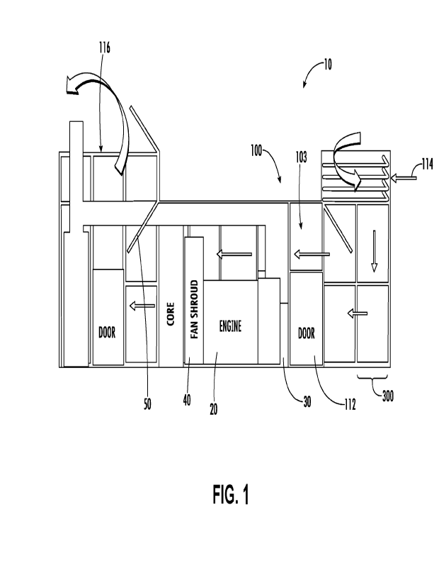
[0041] FIG. 1 is a side cross-sectional view of a genset
assembly 10, according to at
least one embodiment The genset assembly 10 includes an engine 20; a generator
30; an
air driver 40; a genset enclosure, shown as enclosure 100; and deflector
assemblies 50.
The engine 20 may be a diesel engine, a gasoline engine, a natural gas engine,
a dual fuel
engine, a biodiesel engine, an E85 engine, a flex fuel engine, a gas turbine,
or another type
of internal combustion engine or driver. In various embodiments, the engine 20
may be a
high horse power (HHP) engine, such as, for example, an engine capable of
providing
power in the range of 500 hp to 4,500 hp or more. The generator 30 may be an
electric
-7-
CA 03183244 2022- 12- 19
WO 2022/005964
PCT/US2021/039365
power generator, an alternator, or the like. In one embodiment, the engine 20
is coupled to
the generator 30 by, for example, a driveshaft (not shown). In operation, the
engine 20
drives the generator 30 to produce electricity (e.g., power). Embodiments of
the present
disclosure are also applicable for various types of prime movers (mechanical,
electrical,
hydro, and/or fuel cell types) with various power strengths (low, medium, and
high horse
power).
[0042] The air driver 40 is structured to draw air (e.g.,
ventilation air, cooling air, etc.)
from an environment surrounding the enclosure 100 through the enclosure 100 to
cool the
generator 30 and/or other internal components of the genset assembly 10. In at
least one
embodiment, the air driver 40 is a fan. In other embodiments, the air driver
40 includes a
plurality of fans positioned at different locations within the enclosure 100.
In some
embodiment, the fan may be coupled to the engine 20 (e.g., to the engine
driveshaft via a
pulley, etc.) such that a speed of the fan is proportional to a speed of the
engine 20. In
other embodiments, the fan is driven separately from the engine 20 (e.g., via
an electric
fan motor, etc.).
[0043] FIGS. 2-5 shows a perspective, side, front, and bottom
views of the enclosure
100, respectively. The enclosure 100 includes end walls 102 (e.g., container
walls,
sidewalls, etc.) defining an internal volume 103 (e.g., an enclosed space, a
hollow region,
etc. as shown in FIG. 1) for housing the engine 20, the generator 30, the air
driver 40, and
other genset components (see also FIG. 1). The end walls 102 include a
container floor
104, a container roof 106, a first pair of container sidewalls 108, and a
second pair of
container sidewalls 110. Each sidewall of the first pair of container
sidewalls 108 is
disposed at a lateral end of the enclosure 100, while each sidewall of the
second pair of
container sidewalls 110 is disposed at a longitudinal end of the enclosure
100. The first
pair of container sidewalls 108 and the second pair of container sidewalls 110
are arranged
in substantially perpendicular orientation relative to the container floor 104
and container
roof 106. The container floor 104 and the container roof 106 are coupled at
their lateral
and longitudinal edges to edges of the container sidewalls 108 (e.g., to upper
and lower
edges of the container sidewalls 108). At least one door 112 may be provided
in at least
one of the first plurality of container sidewalls 108 and/or the second pair
of container
sidewalls 110 to allow access to the genset assembly 10 (e.g., by maintenance
or repair
personnel). The at least one door 112 allows such personnel to enter the
internal volume
-8-
CA 03183244 2022- 12- 19
WO 2022/005964
PCT/US2021/039365
103 defined by the enclosure 100 and access the genset. The container floor
104, the
container roof 106, the first plurality of container sidewalls 108, and the
second pair of
container sidewalls 110 together seal the enclosure 100 from the surrounding
environment.
The container floor 104, container roof 106, the first plurality of container
sidewalls 108,
and the second plurality of container sidewalls 110 may be formed from any
suitable
material, for example, carbon or mild steel panels, as will be further
described.
[0044] In some embodiments, the enclosure 100 may be disposed on
the ground. In
other embodiments, the enclosure 100 may be mounted on a fuel tank (not shown)
that is
disposed on the ground, or mounted on skids (not shown) that are disposed on
the ground.
In other embodiments, the enclosure 100 may be positioned on a rooftop above
the ground
or another suitable location.
[0045] The enclosure 100 is configured to provide air flow
therethrough to cool the
genset 10 and provide intake air for the engine of the genset assembly 10. As
shown in
FIGS. 1-2, the enclosure 100 includes ventilation air openings including a
ventilation air
intake opening, shown as air inlet 114, and a ventilation air outlet opening,
shown as air
outlet 116. In at least one embodiment, each of the air inlet 114 and the air
outlet 116 are
defined in the container roof 106 and fluidly couple the internal volume 103
with an
environment surrounding the enclosure 100. In the embodiment of FIGS. 1-2, the
air inlet
114 and the air outlet 116 are disposed on opposite ends of the container roof
106. In some
embodiments, the air inlet 114 and/or the air outlet 116 may include louvers
118 or other
elements that allow air to enter the enclosure 100, while redirecting water
(e.g., due to
rainfall) away from the enclosure 100 or to predefined water drainage areas of
the
enclosure 100. In other embodiments, the air inlet 114 and the air outlet 116
may be
provided in another location along the enclosure 100 (e.g., the first pair of
container
sidewalls 108 and/or the second pair of container sidewalls 110).
[0046] The genset assembly 10 includes a deflector assembly
structured to redirect
noise in the air multiple times within the enclosure 100 to attenuate noise
exported from
the enclosure 100. As shown in FIG. 6, the genset assembly 10 includes two
deflector
assemblies, including a first deflector assembly 202 and a second deflector
assembly 204
disposed on an opposite end of the enclosure 100 as the first deflector
assembly 202. The
first deflector assembly 202 and the second deflector assembly 204 are
mechanically
-9-
CA 03183244 2022- 12- 19
WO 2022/005964
PCT/US2021/039365
connected to the container roof 106. In the embodiment of FIG. 6, the first
deflector
assembly 202 is an outlet deflector assembly structured to reflect air
proximate to the air
outlet 116, while the second deflector assembly 204 is an inlet deflector
assembly
structure to reflect air proximate to the air inlet 114. In some embodiments,
a position
(e.g., an angular position, a length, etc.) of the first deflector assembly
202 and the second
deflector assembly 204 is adjustable within the enclosure 100 to minimize
exported noise.
Additional aspects of the structure of the first deflector assembly 202 and
the second
deflector assembly 204 may be found in U.S. Patent Application No. 62/944,943,
filed
December 6, 2019, the entire disclosure of which is hereby incorporated by
reference
herein.
[0047] As shown in FIGS. 1-6, the enclosure 100 is formed
entirely from a plurality of
individual enclosure segments, shown as segments 300. As shown in FIG. 2, the
enclosure
includes a main body portion 120, an air inlet portion 122, and an air outlet
portion 124. In
other embodiments, only a portion of the enclosure 100 may be formed from the
segments
300 (e.g., only the air inlet portion 122 and the air outlet portion 124, only
the main body
portion 120 or a sub-portion thereof, etc.). The main body portion 120 is
formed by
multiple segments 300 that are arranged in series (e.g., end to end, etc.)
along an axial
direction (e.g., longitudinal direction, substantially parallel to a flow
direction through the
main body portion 120, etc.). The air inlet portion 122 and the air outlet
portion 124 are
disposed on the container roof 106, on opposing ends of the container roof
106. A width of
each of the air inlet portion 122 and the air outlet portion 124 is
approximately the same as
a width of the main body portion 120 such that the air inlet portion 122 and
the air outlet
portion 124 each extend between opposing lateral ends of the container roof
106 (e.g.,
between the first pair of sidewalls 108 such that the sidewalls of the air
inlet portion 122
and the air outlet portion 124 are substantially flush with the first
plurality of sidewalls
108). As shown in FIG. 3, a length of the air outlet portion 124 in the axial
direction is
greater than a length of the air inlet portion 122. In other embodiments, the
relative lengths
of the air inlet portion 122 and the air outlet portion 124 may be different.
[0048] As shown in FIG. 3, the main body portion 120 is formed
from 12 individual
segments 300. The segments 300 are arranged end-to-end in substantially
coaxial
arrangement along the axial direction. The segments 300 together form the
internal
volume 103 of the enclosure 100. The number of segments 300 used to form the
enclosure
-10-
CA 03183244 2022- 12- 19
WO 2022/005964
PCT/US2021/039365
100 may differ in various embodiments and depending on the size of the
generator and/or
other components housed within the enclosure 100.
[0049] FIG. 7 shows a perspective view of an individual segment
300 of the enclosure
100 (see FIG. 2). The segment 300 forms part of the main body portion 120 of
the
enclosure 100 (e.g., between doors 112 of the main body portion 120 as shown
in FIG. 3).
As shown in FIG. 7, the segment 300 includes a frame system 302, a plurality
of side
panels 304, a plurality of roof panels 305, a first connector 306, and a
second connector
308. The frame system 302 forms a skeleton support structure (e.g., space
frame, ladder
frame, etc.) for the segment 300 to which the other components are connected.
The frame
system 302 provides structural support for the segment 300 under wind and/or
other
external structural loading. As shown in FIG. 7, the segment 300 is sized to
house a
portion of the genset assembly 10 therein (e.g., at least a portion of the
engine 20, the
generator 30, the air driver 40, etc. as shown in FIG. 1). In the embodiment
of FIG. 7, an
overall width 309 of the segment 300 may be approximately 9-13 feet, for
example. An
overall height 311 of the segment 300 may be approximately 10-14 feet, for
example, and
an overall depth 317 of the segment 300 may be approximately 2-6 feet. In
particular, in at
least one embodiment, the overall width 309 may be between 2-3 times the
overall depth
317. In at least one embodiment, the overall height 311 may be more than 3
times the
overall depth 317, for example and may be greater than the overall width 309.
It should be
appreciated that the foregoing ranges are merely illustrative of
representative dimensions
and that none of the embodiments are limited to such dimensions or the
relative
relationships of such dimensions. In other embodiments, the overall dimensions
of the
segment 300 may be different.
[0050] The frame system 302 includes a plurality of
interconnected frame members
310 including end members 312 and cross members 314 extending between the end
members 312. The end members 312 may be formed of multiple (e.g., four, etc.)
frame
members 310 that are connected at opposing ends of the frame members 310 to
form a
rectangular shape. The frame members 310 may be connected via welding,
mechanical
fasteners, or another suitable joining operation.
[0051] The end members 312 are spaced apart from one another in
an axial direction
and are arranged substantially parallel to one another. The end members 312
are also
-11-
CA 03183244 2022- 12- 19
WO 2022/005964
PCT/US2021/039365
aligned with one another in substantially coaxial arrangement such that a
central axis of a
first one of the end members 312 is co-linear with a central axis of a second
one of the end
members 312. The cross members 314 are engaged with and extend between the end
members 312 to form a plurality of openings 313 (e.g., windows, etc.) along
the outer
perimeter of the frame system 302. The cross members 314 are arranged
substantially
perpendicular to the end members 312 and are coupled to the end members 312 at
opposing ends 315 of the cross members 314. The spacing between the cross
members
314 along a perimeter of the end members 312 may differ in various
embodiments. In the
embodiment of FIG. 7, cross members 314 are positioned at each corner of the
rectangular
profile formed by the end members 312. Along a floor 316 and sidewalls 318 of
the
segment 300, a single cross member 314 is disposed at an intermediate
position,
approximately half way between corners of the rectangular profile. A roof 320
of the
segment 300 includes two cross members 314 spaced at approximately equal
intervals
between the corners of the rectangular profile. In other embodiments, the
number and/or
arrangement of the cross members 314 and/or end members 312 may be different.
[0052] The frame members 310 may be made from any suitable
structural material. As
shown in FIG. 8, each frame member 310 may be a hollow tube of uniform cross-
section
such as a square/rectangular hollow tube, a circular hollow tube, etc. In
other
embodiments, the frame members 310 are structural support beams such as an I-
channel,
C-channel, T-channel, or another suitable channel shape or flat plate, or
combinations
thereof. In yet other embodiments, the frame members 310 are solid rods (e.g.,
solid
rectangular or circular bar stock, etc.). In yet other embodiments, the frame
members 310
are a combination of different structural element types. The frame members 310
may be
made from carbon steel tubing (e.g., ASTM A500) or another suitable material.
The
dimensions of the frame members 310 may differ depending on the overall size
of the
segment 300. For example, in the embodiment of FIG. 8, the square tubing may
be 4 inch
x 4 inch structural steel tubing, 2 inch x 2 inch structural steel tubing, or
another suitable
size. It should be appreciated that such dimensions are purely exemplary and
that the
embodiments are not limited to any of such dimensions or ranges thereof
[0053] The side panels 304 form a portion of the first pair of
container sidewalls 108 of
the enclosure 100 (see FIG. 2). As shown in FIG. 7, the plurality of side
panels 304 are
coupled to opposing sides 319 (e.g., lateral sides, etc.) of the frame system
302. The side
-12-
CA 03183244 2022- 12- 19
WO 2022/005964
PCT/US2021/039365
panels 304 are disposed within and substantially cover a respective one of the
plurality of
openings 313 along the opposing sides 319. As shown in FIGS. 9-10, the side
panels 304
are box panels including a main body 322 and a plurality of main body flanges
324
extending outwardly from a perimeter of the main body 322 (e.g., outwardly
from the outer
four perimeter edges of the main body 322). The main body 322 is a rectangular
prism
sized to substantially cover a respective one of the plurality of openings 313
(see FIG. 7).
The main body 322 includes an inner skin 323 and an outer skin 325. The outer
skin 325 is
oriented parallel to the inner skin 323 and spaced apart from the inner skin
323 to form an
air cavity (e.g., air gap, a hollow interior volume, etc.) therebetween. In
the embodiment
of FIG. 9, the inner skin 323 and the outer skin 325 are planar sheets of
material (e.g.,
carbon steel, etc.). The outer edges of the inner skin 323 are bent at a 90
angle to form the
perimeter walls of the box panel. The outer skin 325 is then welded or
otherwise joined
with the inner skin 323 to form the box panel. In other embodiments, the
perimeter walls
of the box panel may be separately formed from the inner skin 323 and the
outer skin 325
or at least partially integrally formed with the outer skin 325. In yet other
embodiments, at
least one of the side panels 304 can be made of single sheet and without an
air cavity.
[0054] As shown in FIG. 10, the main body flanges 324 are
substantially flush with an
outward facing surface 328 of the main body 322. Each of the main body flanges
324 is
cantilevered from the main body 322 to form a ledge 329 that is engageable
with one of the
end members 312 and the cross members 314 of the frame system 302 so as to
support the
main body 322 within the opening 313 (e.g., such that the main body 322 is
surrounded by
the combination of end members 312 and the cross members 314 as shown in FIG.
7). The
main body 322 is sized to fit within the openings 313, which facilitates
positioning and
alignment of the side panels 304 along opposing sides of the frame system 302.
The main
body flanges 324 may be welded, mechanically fastened, or otherwise coupled to
the frame
system 302 to secure the side panels 304 to the frame system 302. In the
embodiment of
FIGS. 9-10, the main body flanges 324 are formed from the inner skin 323, by
bending the
outer edges of the inner skin 323 at a 90 angle outwardly from the air cavity
and the
perimeter wall.
[0055] The roof panels 305 form a portion of the container roof
106 of the enclosure
100 (see FIG. 2). As shown in FIG. 7, the plurality of roof panels 305 are
coupled to the
roof 320 of the frame system 302 and extend laterally between the opposing
sides 319 of
-13-
CA 03183244 2022- 12- 19
WO 2022/005964
PCT/US2021/039365
the frame system 302. The roof panels 305 are oriented perpendicular to the
plurality of
side panels 304. The roof panels 305 are disposed within and substantially
cover the
openings 313 along the roof 320 of the frame system 302. As shown in FIG. 10,
the design
of the roof panels 305 is substantially similar to the design of the side
panels 304 (FIGS. 9-
10). The roof panels 305 are rectangular-shaped box panels including a main
body 330
and a plurality of main body flanges 332 extending outwardly from a perimeter
of the main
body 330. Each one of the main body flanges 332 is cantilevered from the main
body 330
to form a ledge that is engageable with one of the end members 312 and the
cross members
314 of the frame system 302 so as to support the main body 330 within the
opening 313
(e.g., such that the main body 330 is surround by the combination of end
members 312 and
the cross members 314 as shown in FIG. 7). The main body 330 is sized to fit
within the
openings 313, which facilitates positioning and alignment of the roof panels
305 along the
roof 320. The main body flanges 332 may be welded, mechanically fastened, or
otherwise
coupled to the frame system 302 to secure the roof panels 305 to the frame
system 302. In
some embodiments, the roof panels 305 also form a portion of the container
floor 104 of
the enclosure 100 (see FIG. 2) and are coupled to the floor 316 of the frame
system 302
opposite the roof 320.
[0056] As shown in FIG. 7, the frame system 302, the plurality
of side panels 304, and
the plurality of roof panels 305 together define a portion of the overall
enclosure. In FIG.
7, the portion is shown as enclosure portion 334 (e.g., axial portion, etc.)
of the internal
volume 103 (see also FIGS. 1 and 6). The enclosure portion 334 has a first
open end 336
and a second open end 338 that fluidly connect the enclosure portion 334 to
the
surrounding environment and/or enclosure portions of adjacent enclosure
segments.
[0057] As shown in FIG. 7, the size of the side panels 304 is
different from the size of
the roof panels 305 in a single direction. In particular, as shown in FIGS. 9
and 11, a width
340 of the side panels 304 in an axial direction is approximately equal to a
width 342 of the
roof panels 305. A length 344 of the side panels 304 in a lateral direction
(e.g.,
perpendicular to the axial direction) is different from a length 346 of the
roof panels 305.
Among other benefits, the difference in length between the side panels 304 and
the roof
panels 305 allows for different increments of adjustability in the overall
width 348 and
overall height 350 of the segment 300 (see FIG. 7). In some embodiments, such
a
configuration allows for adjustability while ensuring a uniform axial length
(e.g., depth) of
-14-
CA 03183244 2022- 12- 19
WO 2022/005964
PCT/US2021/039365
the segment 300 along the perimeter of the segment 300. The different
increments of
adjustability may correspond with variations in the length and width of the
genset for
different genset sizes (e.g., so as to accommodate variations in the length
and the width of
the genset, which changes as different genset models are employed). In
particular, such
increments of adjustability serve to minimize the overall footprint of the
genset assembly
for a given genset size. In other embodiments, the side panels 304 may be
approximately
the same size as the roof panels 305. In yet other embodiments, the side
panels 304 and/or
roof panels 305 may each include panels of different sizes.
[0058] In various embodiments, inner surfaces of the container
floor 104, the container
roof 106, the first pair of container sidewalls 108, and the second pair of
container
sidewalls 110 (see FIG. 1) may be lined with acoustic dampening materials
(e.g., acoustic
material lining, etc.) structured to absorb and attenuate noise produced by
the genset
assembly 10. The noise may be generated by internal components such as the
engine 20,
the generator 30, the fan(s), or the like. Alternatively, or in combination,
the noise may be
produced as a result of air flow passing through the enclosure 100 via the air
inlet 114 and
the air outlet 116. FIG. 12 shows a side cross-sectional view through one of
the side panels
304 after assembly. As shown, each of the side panels 304 engages the frame
system 302
(see FIG. 7) such that the outer skin 325 faces an environment surrounding the
enclosure
100 and the inner skin 323 faces the internal volume 103. The inner skin 323
and outer
skin 325 may be made from a metal such as carbon or mild steel, or another
structurally
robust material. In the embodiment of FIG. 12, each side panel 304 is a box
panel that
includes an air cavity 327 that is "sandwiched" or otherwise disposed between
the inner
skin 323 and the outer skin 325. Among other benefits, the air cavity 327 may
further
attenuate noise produced by the genset assembly 10 (see also FIG. 1). An
acoustic
damping material 126 is mechanically connected (e.g., bonded with an adhesive
product,
coupled using magnets, coupled using rivets, etc.) to the inner skin 323
within the internal
volume 103. In some embodiments, the acoustic damping material 126 completely
lines
the inner skin 323 along the container end walls 102 (e.g., the side panels
304, the roof
panels 305, etc.). In other embodiments, the acoustic damping material 126
includes
individual sheets placed along portions of at least one of the end walls 102.
For example,
the acoustic damping material 126 may be formed in 0.5 ft. x 1 ft. sheets, 1
ft. x 2 ft.
sheets, 2 ft. x 4 ft. sheets, 4 ft. x 8 ft. sheets, or any other suitable
dimensions. In various
-15-
CA 03183244 2022- 12- 19
WO 2022/005964
PCT/US2021/039365
embodiments, the acoustic damping material 126 may include fibrous (e.g., rock
wool,
glass wool, mineral wool, etc.), non-fibrous (e.g., polyurethane foam,
melamine foam, etc.)
materials, or the like.
[0059] The segment 300 is structured to engage with and couple
to other enclosure
segments that are placed adjacent to the first open end 336 and the second
open end 338 so
as to expand the enclosure portion 334 in the axial direction. As shown in
FIGS. 13-14,
the segment 300 includes a first connector 306 and a second connector 308
structured to
facilitate alignment and coupling between adjacent enclosure segments. The
first
connector 306 is one of a plurality of first connectors 306 coupled to the end
member 312
of the frame system 302 along a perimeter of the first open end 336. In the
embodiment of
FIG. 13, the segment 300 includes eight first connectors 306 that are spaced
in
approximately equal intervals along the perimeter of the first open end 336.
In other
embodiments, the segment 300 may include additional or fewer first connectors
306.
[0060] The second connector 308 is one of a plurality of second
connectors 308
coupled to the end member 312 of the frame system 302 along a perimeter of the
second
open end 338. Each one of the second connectors 308 is axially aligned with a
respective
one of the plurality of first connectors 306 such that a central axis of each
one of the
plurality of second connectors 308 is substantially aligned and collinear with
a central axis
of a respective one of the plurality of first connectors 306. In other words,
the first
connectors 306 and the second connectors 308 are arranged in axially aligned
pairs along
the perimeter of the frame system 302.
[0061] The first connector 306 is engageable with the second
connector 308 to align
and/or connect adjacent segments 300. As shown in FIG. 15, each of the first
connectors
306 is an extension piece that extends axially away from the first open end
336 of the
segment 300 (and end member 312). The extension piece may be a cylindrical
pin, a bolt
(or other threaded connector), a stud, rod, or another suitable extension. In
other
embodiments, the cross-sectional shape of at least one of the first connectors
306 may be
different (e.g., rectangular, oval, etc.). In yet other embodiments, the first
connector 306
may another form of male connector, fitting, and/or coupler. As shown in FIG.
16, each of
the second connectors 308 is an opening 352 that is sized to receive a first
connector 306
therein. The opening 352 is shaped complementary with the first connector 306
(e.g., a
-16-
CA 03183244 2022- 12- 19
WO 2022/005964
PCT/US2021/039365
circular recess area, etc.) and is sized to substantially prevent movement of
adjacent
segments 300 normal to the axial direction (e.g., side to side, up and down,
etc.). For
example, the opening 352 may be sized for slip fit with the first connector
306. In other
embodiments, the second connector 308 may be a threaded nut and/or another
form of
female connector, fitting, and/or coupler. In some embodiments, the first
connector 306
and the second connector 308 may be detachably coupled so that adjacent
segments 300
can be disassembled for transport and/or repair. In other embodiments, the
first connector
306 and the second connector 308 provide alignment and a third connector that
is separate
from the first connector 306 and the second connector 308 is used to connect
the segments
300. In yet other embodiments, the first connectors 306 and/or the second
connectors 308
are disposed on other parts of the segment 300 (e.g., other parts of the frame
system 302,
side panels 304, and/or roof panels 305). In some embodiments, each segment
300
additionally includes a sealing member such as a gasket, weather stripping, or
another
material to form a watertight seal between adjacent segments 300 and to
prevent water
ingestion into the internal volume 103 (see FIGS. 1 and 7).
[0062] The arrangement of the frame system 302, side panels 304,
and roof panels 305
described with reference to the segment 300 of FIG. 7 is shown for
illustrative purposes
only. Many alternatives and combinations are possible without departing from
the
inventive concepts disclosed herein. For example, the construction of the
segment 300
may be modified to accommodate a door, air vents, and/or other components of
the
enclosure 100 by rearranging the position of at least one frame member 310.
For example,
FIGS. 17-18 show an air inlet portion 122 (e.g., air intake assembly, etc.) of
the enclosure
100 of FIGS. 1-2. As shown, the air inlet portion 122 is formed from a
plurality of
interconnected frame members 410 that are arranged end-to-end to form a
skeleton support
structure. The air inlet portion 122 also includes a plurality of roof panels
405 engaged
with a roof of the support structure and a plurality of air intake vents 454
engaged with
sides of the support structure in substantially perpendicular orientation
relative to the roof.
The roof panels 405 may be the same as or similar to the roof panels 305
described with
reference to FIG. 11. As shown in FIG. 18, the air intake vents 454 have a box
panel
structure as described with reference to FIG. 9, but include a plurality of
angled louvers
456 in place of an inner and outer skin (e.g., louvers 456 disposed within an
air cavity
region of the box panel defined by the perimeter walls of the box panel). The
air inlet
-17-
CA 03183244 2022- 12- 19
WO 2022/005964
PCT/US2021/039365
portion 122 may additionally include at least one first connector and/or
second connecter to
facilitate alignment between the air inlet portion 122 and other segments 300
of the
enclosure 100 (see FIG. 2).
[0063] Referring now to FIG. 19, a method 500 of making a genset
enclosure is
shown, according to an embodiment. The enclosure may be the same as or similar
to the
enclosure 100 described with reference to FIGS. 1-2 and/or the enclosure
segment
described with reference to FIG. 7. As such, similar numbering will be used to
identify
similar components.
[0064] At 502, a frame system (e.g., frame system 302) is
provided. Operation 502
may include providing a plurality of interconnected frame members (e.g., frame
members
310) and interconnecting (e.g., welding, fastening, etc.) opposing ends of
each one of the
plurality of frame members. Operation 502 may also include providing
connectors (e.g.,
first connectors 306 and second connectors 308) and placing the connectors on
opposing
ends of the frame system. Operation 502 may additionally include joining the
connectors
with at least one frame member (e.g., via welding, fastening, or another
suitable joining
operation).
[0065] At 504, a plurality of side panels (e.g., side panels
304) and a plurality of roof
panels (e.g., roof panels 305) are provided. In other embodiments, operation
504 may
include providing a single side panel and a single roof panel. At 506, each of
the plurality
of side panels is connected to one of two opposing sides of the frame system
to
substantially cover the opposing sides. Operation 506 may include aligning
each side
panel with a respective one of the openings (e.g., openings 313) in the frame
system along
one of the opposing sides and engaging the side panel with a respective one of
the
openings (e.g., by pressing the side panel at least partially into the
opening). Operation
506 may further include welding, fastening, or otherwise coupling at least one
main body
flange (e.g., main body flange 324) of the side panel to the frame members.
[0066] At 508, each of the plurality of roof panels are placed
onto a roof of the frame
system in substantially perpendicular orientation relative to the opposing
sides of the
frame system and side panels. Operation 508 may include aligning each roof
panel with a
respective one of the windows of the frame system along the roof and engaging
the roof
-18-
CA 03183244 2022- 12- 19
WO 2022/005964
PCT/US2021/039365
panel with a respective one of the openings (e.g., by pressing the roof panel
at least
partially into the opening). At 510, each of the plurality of roof panels is
connected to the
roof of the frame system to substantially cover the roof. Operation 510 may
include
welding, fastening, or otherwise coupling at least one main body flange (e.g.,
main body
flange 332) of the roof panel to the frame members. Operations 502 through 510
may
form a first enclosure segment of the genset enclosure.
[0067] In some embodiments, the method 500 further includes
joining multiple
segments (e.g., segments 300) to expand the internal volume (e.g., internal
volume 103)
circumscribed (e.g., encompassed, etc.) by the enclosure along an axial
direction. The
method 500 may include providing a second enclosure segment and placing the
second
enclosure segment adjacent to the first open end of the first enclosure
segment. The
method 500 may include axially aligning the first enclosure segment with the
second
enclosure segment (e.g., aligning the first connector of the first enclosure
segment with the
second connector of the second enclosure segment). The method 500 may further
include
connecting the second enclosure segment to the first enclosure segment; for
example, by
engaging the first connector of the first enclosure segment with the second
connector of
the second enclosure segment (e.g., by moving the second enclosure segment
axially
toward the first enclosure segment). In other embodiments, the method 500 may
include
additional, fewer, and/or different operations.
[0068] It should be noted that the term "example" as used herein
to describe various
embodiments is intended to indicate that such embodiments are possible
examples,
representations, and/or illustrations of possible embodiments (and such term
is not
intended to connote that such embodiments are necessarily extraordinary or
superlative
examples).
[0069] As utilized herein, the term "substantially" and similar
terms are intended to
have a broad meaning in harmony with the common and accepted usage by those of
ordinary skill in the art to which the subject matter of this disclosure
pertains. It should be
understood by those of skill in the art who review this disclosure that these
terms are
intended to allow a description of certain features described and claimed
without
restricting the scope of these features to the precise numerical ranges
provided.
Accordingly, these terms should be interpreted as indicating that
insubstantial or
-19-
CA 03183244 2022- 12- 19
WO 2022/005964
PCT/US2021/039365
inconsequential modifications or alterations of the subject matter described
and claimed
(e.g., within plus or minus five percent of a given angle or other value) are
considered to
be within the scope of the invention as recited in the appended claims.
[0070] The terms "coupled," "connected," and the like as used
herein mean the joining
of two members directly or indirectly to one another. Such joining may be
stationary (e.g.,
permanent) or moveable (e.g., removable or releasable). Such joining may be
achieved
with the two members or the two members and any additional intermediate
members being
integrally formed as a single unitary body with one another or with the two
members or
the two members and any additional intermediate members being attached to one
another.
[0071] It is important to note that the construction and
arrangement of the various
exemplary embodiments are illustrative only. Although only a few embodiments
have
been described in detail in this disclosure, those skilled in the art who
review this
disclosure will readily appreciate that many modifications are possible (e.g.,
variations in
sizes, dimensions, structures, shapes and proportions of the various elements,
values of
parameters, mounting arrangements, use of materials, colors, orientations,
etc.) without
materially departing from the novel teachings and advantages of the subject
matter
described herein. Other substitutions, modifications, changes and omissions
may also be
made in the design, operating conditions and arrangement of the various
exemplary
embodiments without departing from the scope of the embodiments described
herein.
[0072] While this specification contains many specific
implementation details, these
should not be construed as limitations on the scope of any embodiment or of
what may be
claimed, but rather as descriptions of features specific to particular
implementations of
particular embodiments. Certain features described in this specification in
the context of
separate implementations can also be implemented in combination in a single
implementation Conversely, various features described in the context of a
single
implementation can also be implemented in multiple implementations separately
or in any
suitable subcombination. Moreover, although features may be described above as
acting
in certain combinations and even initially claimed as such, one or more
features from a
claimed combination can in some cases be excised from the combination, and the
claimed
combination may be directed to a subcombination or variation of a
subcombination.
-20-
CA 03183244 2022- 12- 19