Note: Descriptions are shown in the official language in which they were submitted.
WO 2021/262707
PCT/US2021/038464
WEAR RESISTANT BORIDE FORMING FERROUR ALLOYS FOR POWDER BED FUSION
ADDITIVE MANUFACTURING
CROSS-REFERENCE TO RELATED APPLICATIONS
100011 This application claims the benefit of U.S. provisional
application Serial No.
63/042202 filed June 22, 2021 the disclosure of which is hereby incorporated
in its entirety by
reference herein.
TECHNICAL FIELD
[0002] The present application relates to ferrous (steel) alloy
compositions that can be
printed by powder bed fusion additive manufacturing.
BACKGROUND
[0003] In the most general form, additive manufacturing, also
known as 3D printing,
involves layer-by-layer deposition of materials to "build" or "print" an
object in three dimensions.
There are several advantages in manufacturing this way, including producing
complex geometries,
reducing production times, innovating rapidly, eliminating inventory, and
saving material costs.
[0004] In tooling, specifically, conformal cooling channels are
an example of a complex
geometry that would otherwise not be possible or would be cost restrictive by
subtractive
manufacturing. Conformal cooling channels are internal pathways that follow
closely to the shape
and direction of exterior-facing surfaces to enable maximum thermal management
by fluid pumped
through the channels. Conformal cooling channels can extend tool lifetime and
reduce part
production cycle times (i.e. the time required to produce a part by the tool),
both of which can lower
costs.
SUMMARY
[0005] In at least one embodiment, a method of layer-by-layer
construction of a metallic part
is provided. particles of an iron-based alloy are supplied. The iron-based
alloy has Cr in an amount
1
CA 03183775 2022- 12- 21
WO 2021/262707
PCT/US2021/038464
ranging from 9.0 wt. % to 16.0 wt. %; Ni in an amount of 5.0 wt. or less %; Mo
in an amount of 3.0
wt. or less %, Mn in an amount of 3.0 wt. or less %, C in an amount ranging
fioni 0.1 wt. % to 0.30
wt. %; B in an amount of 1.0 wt. or less %. One or more elements selected from
Cu, W, or V are
present. When Cu is present it is present in an amount up to 2.5 wt. %; when W
is present it is
present in an amount up to 7.5 wt. %; when V is present it is present in an
amount up to 3.5 wt. %.
The balance of the iron-based alloy contains Fe. An as-built metallic part is
formed at least in part
by powder bed fusion including melting the particles into a molten state and
cooling and forming
one or more solidified layers of the iron-based alloy containing a martensitic
matrix and one or more
of a Cr-boride, W-boride when W is present or V-boride when V is present. In
the as-built part has a
HRC hardness HI and an abrasion wear resistance WI (mass loss in grams via
ASTM G65-16e1
Procedure A). The as-built part is heat treated, wherein the heat-treated part
indicates a second value
for FIRC hardness (H2) and abrasion wear resistance (W2) where W2 < Wl.
[0006] In another embodiment, the as-built part has a tensile
strength of at least 1000 MPa, a
yield strength of at least 700 MPa, an elongation of at least 0.25 %, and a
hardness (HRC) of at least
40.
[0007] In another embodiment, after heat treatment, the metallic
part has an elongation of at
least 5.0 %, a HRC hardness of at least 50 and abrasion wear resistance (mass
loss in grams via
ASTM G65-16e1 Procedure A) of less than or equal to 1.90.
[0008] In another embodiment, the heat treatment comprises
heating at a temperature of 900
C to 1200 C for 0.5 to 8.0 hours.
[0009] In another embodiment, Cu when present is present at a
level of 0.15 wt. % to 0.30
wt. %, when W is present it is present at a level of 0.1 wt. % to 5.5 wt. %
and when V is present it is
present at a level of 0.1 wt. % to 2.25 wt. %.
[0010] In another embodiment, the alloy after heat treating
contains a Cr-rich boride phase
100111 In another embodiment, the alloy contains Win an amount of
0.1 wt. % to 5.5 wt. %
and the alloy after heat treating contains a W-rich boride phase.
2
CA 03183775 2022- 12- 21
WO 2021/262707
PCT/US2021/038464
100121 In another embodiment, the alloy contains V in an amount
of 0.1 wt. % to 2.25 wt. %
and the alloy after heat treating contains a V-rich boride phase.
100131 In another embodiment, the alloy has Cr in an amount
ranging from 9.0 wt. % to 19.0
wt. %; Ni in an amount up to 3.0 wt. %; Mo in an amount ranging from 0.2 wt. %
to 0.8 wt. %; Mn
in an amount ranging from 0.75 wt. % to 3.0 wt. %; C in an amount ranging from
0.1 wt. % to 0.25
wt. %; B in an amount ranging from 0.25 wt. % to 0.75 wt. %.
100141 In another embodiment, the alloy, when Cu is present it is
present in an amount up to
0.8 wt. %; when W is present it is present in an amount up to 5.5 wt. %; when
V is present it is
present in an amount up to 2.5 wt. %.
100151 In at least one embodiment, a method of layer-by-layer
construction of a metallic part
comprising supplying particles of an iron-based alloy, the iron-based alloy
comprising Cr in an
amount ranging from 9.0 wt. % to 16.0 wt. %, Ni in an amount ranging from 2.0
wt. % to 3.0 wt. %,
Mo in an amount ranging from 0.2 wt. % to 0.8 wt. %, Mn in an amount ranging
from 0.75 wt. % to
3.0 wt. %, C in an amount ranging from 0.1 wt. % to 0.25 wt. %, B in an amount
ranging from 0.25
wt. % to 0.25 wt. %, one or more elements selected from Cu, W, or V wherein
when Cu is present it
is present in an amount up to 0.3 wt. %, when W is present it is present in an
amount up to 5.5 wt. %,
when V is present it is present in an amount up to 2.25 wt. %. The balance of
the iron-based alloy
contains Fe. One forms an as-built metallic part at least in part by powder
bed fusion comprising
melting the particles into a molten state and cooling and forming one or more
solidified layers of the
iron-based alloy containing a martensitic matrix and one or more of a Cr-
boride, W-boride when W
is present or V-boride when V is present. In the as-built condition the part
has a HRC hardness H1
and an abrasion wear resistance WI (mass loss in grams via ASTM G65-16e1
Procedure A) and heat
treating the part wherein the part indicates a second value for EIRC hardness
(H2) and abrasion wear
resistance (W2) that are as follows: H2 = H1 +/- 10 and W2 < Wl.
BRIEF DESCRIPTION OF THE DRAWINGS
100161 Figure 1 illustrates a Scheil solidification curve
calculated for Alloy Al.
100171 Figure 2 illustrates a Scheil solidification curve
calculated for Alloy A3.
3
CA 03183775 2022- 12- 21
WO 2021/262707
PCT/US2021/038464
[0018] Figure 3 illustrates a Scheil solidification curve
calculated for Alloy A4.
[0019] Figure 4 illustrates the calculated martensite start
temperature and carbon content of
austenite formed during solidification of Alloy Al.
[0020] Figure 5Error! Reference source not found. illustrates the
calculated martensite
start temperature and carbon content of austenite formed during solidification
of Alloy A3.
[0021] Figure 6 illustrates the calculated martensite start
temperature and carbon content of
austenite formed during solidification of Alloy A4.
[0022] Figure 7 illustrates the X-ray diffraction results of PBF
printed bar of Alloy Al.
100231 Figure 8 illustrates a microstructure of as-built Alloy
Al.
100241 Figure 9 illustrates a microstructure of as-built Alloy
A3.
100251 Figure 10 illustrates a microstructure of as-built Alloy
A4.
[0026] Figure 11 illustrates a micrograph of as-built Alloy Al.
100271 Figure 12 illustrates a micrograph of as-built Alloy A2
100281 Figure 13 illustrates a micrograph of as-built Alloy A3.
100291 Figure 14 illustrates a micrograph of as-built Alloy A4.
100301 Figure 15 illustrates a calculated equilibrium phase
diagram of Alloy Al.
[0031] Figure 16 illustrates a calculated equilibrium phase
diagram of Alloy A3.
100321 Figure 17 illustrates a calculated equilibrium phase
diagram of Alloy A4.
100331 Figure 18 illustrates a microstructure of PBF printed bar
of Alloy Al after heat
treatment with aging step at 1100 C for 2 hours.
4
CA 03183775 2022- 12- 21
WO 2021/262707
PCT/US2021/038464
100341 Figure 19 illustrates a microstructure of PBF printed bar
of Alloy Al after heat
treatment with aging step at 1100 C for 4 hours.
[0035] Figure 20 illustrates a microstructure of PBF printed bar
of Alloy Al after heat
treatment with aging step at 1100 C for 8 hours
100361 Figure 21 illustrates a microstructure of PBF printed bar
of Alloy A3 after heat
treatment with aging step at 1100 C for 2 hours.
100371 Figure 22 illustrates a microstructure of PBF printed bar
of Alloy A3 after heat
treatment with aging step at 1100 C for 8 hours.
100381 Figure 23 illustrates a microstructure of PBF printed bar
of Alloy A4 after heat
treatment with aging step at 1100 C for 8 hours.
DETAILED DESCRIPTION
100391 As required, detailed embodiments of the present invention
are disclosed herein;
however, it is to be understood that the disclosed embodiments are merely
exemplary of the
invention that may be embodied in various and alternative forms. The figures
are not necessarily to
scale; some features may be exaggerated or minimized to show details of
particular components.
Therefore, specific structural and functional details disclosed herein are not
to be interpreted as
limiting, but merely as a representative basis for teaching one skilled in the
art to variously employ
the present invention.
100401 There are several metal additive manufacturing methods.
Additive manufacturing
may be used for making tooling used in industrial manufacturing processes,
such as metal die
casting, injection molding, hot stamping, and compression forming. One
additive manufacturing
method for making tooling is laser powder bed fusion (L-PBF or simply "PBF").
PBF can produce
nearly 100% dense pieces with properties similar or better than those of their
wrought counterparts
while achieving dimensional tolerances, near-net shape and surface roughness
that require no to
minimal post-printing finishing. Furthermore, the size of the pieces printed
by PBF are limited only
by the size of the equipment. Other common metal additive manufacturing
methods such as
CA 03183775 2022- 12- 21
WO 2021/262707
PCT/US2021/038464
binderjet or direct energy deposition (DED) have limitations in one or more of
these aspects. For
example, the maximum density bindeijet typically achieves is less than 99% and
the size is limited
by the need to remove binder entrapped in the part during printing. In DED,
the tolerances and
surface finish require post-printing finishing. Beyond tooling, other
specialty parts that require high
performance and reliability, such as those used in aerospace and biomedical
applications, also prefer
PBF for these same reasons.
100411 One aspect where PBF is disadvantaged over other methods
with respect to tooling is
the availability of printable tool steels. Conventional wrought tool steels
that provide the requisite
properties, including hardness and wear resistance, cannot be printed
efficiently or economically by
PBF without cracking. H13, one of the most commonly used tool steels, requires
printing relatively
slowly (typically 9 cm3/hr or less) or preheating the powder bed to 300 C or
higher to avoid
cracking. Implementing either of these options increases printing time, and
thus cost, while the latter
also jeopardizes quality and consistency. Even then, these strategies are not
guaranteed to prevent
cracking when large pieces are printed.
100421 Steels that are printable by PBF such as 316L, M300, and
17-4 PH, either do not have
the hardness, wear resistance or both for many tooling applications. M300 for
example can have
relatively high hardness but the abrasion wear resistance is nominally half
that of H13. Additionally,
steels like M300 and 17-4 PH are relatively soft after printing, requiring a
post-printing aging heat
treatment to increase hardness, which adds manufacturing time and costs.
100431 The disclosure presented here addresses the need for an
alloy composition that can be
used to print tools and specialty parts by PBF with a combination of
relatively high hardness,
strength, elongation, and wear resistance.
100441 The present disclosure describes ferrous alloy
compositions that are printable by
powder bed fusion (PBF) methods and have a combination of relatively high
hardness and wear
resistance in the "as-built" and "heat-treated" states. Printability in this
context refers to the ability
to additively manufacture or 3D print a part preferably without defects such
as cracking or porosity.
The -as-built" state is defined as that produced by the PBF printer that
achieves the indicated
mechanical properties in such as-built condition. The as-built state is
contemplated to include
6
CA 03183775 2022- 12- 21
WO 2021/262707
PCT/US2021/038464
heating to relieve stress that may otherwise be present in the as-built part.
The combination of
printability and properties is achieved by formulating chemistries
specifically for the powder bed
fusion process.
10045] As noted above, the alloy comprises Cr at 9.0 wt. % to
16.0 wt. %, Ni at 2.0 wt. % to
3.0 wt. %, Mo at 0.2 wt. % to 0.8 wt. %, Mn at 0.75 wt. % to 3.0 wt. %, Cat
0.1 wt. % to 0.25 wt. %
and B at 0.25 wt. % to 0.75 wt. %. The alloy may include one or more elements
selected from Cu,
W or V wherein when Cu is present in the alloy, it is present in an amount of
up to 0.3 wt. % or less,
when W is present in the alloy, it is present in an amount of up to 5.5 wt. %
and when V is present in
the alloy, it is present in an amount of up to 2.25 wt. %. The layer-by-layer
construction of such
alloy therefore provides for the formation of a martensitic matrix containing
one or more of a Cr-
boride, W-boride when W is present, or V-boride when V is present. It is noted
that reference to the
presence of a martensitic matrix for the recited borides does not exclude the
presence of some
retained austenite/ferrite that may also be present in the printed alloy part.
100461 The alloy composition may therefore comprise Cr at 9.0 wt.
`)/0 to 16.0 wt. %, Ni at
2.0 wt. % to 3.0 wt. %, Cu at 0.15 wt. % to 0.30 wt. %, Mo at 0.2 wt. % to 0.8
wt. %, Mn at 0.75 wt.
% to 3.0 wt. %, C at 0.1 wt. % to 0.25 wt. % and B at 0.25 wt. % to 0.75 wt.
%. The balance is then
Fe. Such alloy as noted above contains Cr-boride in a martensitic matrix. In
addition, upon heat
treatment of the as-built alloy part, a Cr-rich boride can be formed, which is
reference to the feature
that the dominant species of metallic element in the borides present is Cr. By
way of example, for
the boride M2B CB discussed further herein, the dominant metallic element in
such boride would be
Cr.
100471 The alloy composition may therefore comprise Cr at 9 wt. %
to 16 wt. %, Ni at 2.0
wt. % to 3.0 wt. %, Mo at 0.2 wt. % to 0.8 wt. %, Mn at 0.75 wt. % to 3.0 wt.
%, Cat 0.1 wt. % to
0.25 wt. %, B at 0.25 wt. % to 0.75 wt. % and W at 0.1 wt. % to 5.5 wt. %. The
balance is then Fe.
Such alloy as noted above contains W-boride in a martensitic matrix. In
addition, upon heat
treatment of the as-built alloy part, a W-rich boride can now be formed, which
is reference to the
feature that the dominant species of metallic element in the borides present
is W. By way of
example, for the boride M2B C16 discussed further herein, the dominant
metallic element in such
boride would be W.
7
CA 03183775 2022- 12- 21
WO 2021/262707
PCT/US2021/038464
100481 The alloy composition may therefore comprise Cr at 9 wt. %
to 16 wt. %, Ni at 2.0
wt. % to 3.0 wt. %, Mo at 0.2 wi. % to 0.8 wt. %, Mn at 0.75 wt. % to 3.0 wt.
%, C at 0.1 wt. % to
0.25 wt. %, B at 0.25 wt. % to 0.75 wt. % and Vat 0.1 wt. % to 2.25 wt. %. The
balance is then Fe.
Such alloy as noted above contains V-boride in a martensitic matrix In
addition, upon heat treatment
of the as-built alloy part, a V-rich boride can now be formed, which is
reference to the feature that
the dominant species of metallic element in the borides present is V. By way
of example, for the
boride MB B33 discussed further herein, the dominant metallic element in such
boride would be V.
100491 With regards to the alloy compositions herein, it should
be noted that they may
contain incidental impurities. Such incidental impurities may include the
impurities present in a
given commercially available reagent element selected for preparation of the
alloy compositions.
The incidental impurities may also result from the powder production process,
such as nitrogen from
gas atomization. The level of such incidental impurities may therefore range
up to but not including
0.1 wt. %, any may e.g., include nitrogen or some other residual element,
again being present at a
level of up to but not including 0.1 wt. %.
100501 A layer herein is formed by melting of the alloys in
powder form, wherein the alloy
powder contains particles that are of a size of 1.0 micron to 150 microns in
diameter. In another
embodiment, the powder contains particles that are of a size of 10 micron to
100 micron in diameter.
In another embodiment, the powder contains particles that are of a size of 15
micron to 80 micron in
diameter. Such powder form may be provided by gas atomization or water
atomization of the
aforementioned alloy compositions. The powder is then spread onto a building
surface in a layer
that is 10 microns to 200 microns thick. In another embodiment, the powder is
then spread onto a
building surface in a layer that is 20 microns to 100 microns thick. In
another embodiment, the
powder is then spread onto a building surface in a layer that is 30 microns to
80 microns thick. One
employs a high energy light source, such as a laser or electron beam followed
by solidification of the
melted powder.
100511 Forming one or more layers in this way in any direction or
orientation results in a
volume of material that has the following as-built properties: a hardness of
35 HRC to 56 HRC as
measured by ASTM E18-20, abrasion wear loss of 2.2 g or less as measured by
ASTM G65-16e1
Procedure A, yield strength of at least 700 MPa, tensile strength of at least
1000 MPa, and
8
CA 03183775 2022- 12- 21
WO 2021/262707
PCT/US2021/038464
elongation of at least 0.25% as measured by ASTM E8M-16ael. In addition, the
as-built alloys have
a porosity of less than or equal to 1.0 % as measured by optical microscopy
per ASTM E1245-03.
100521 The alloys in the as-built condition are then heat treated
in a manner that is designed
to influence or improve one or more properties, such as the abrasion wear
resistance of the part. The
heat treatment is also one that is designed to increase the diameter of the
borides that are present in
the as-built condition. Accordingly, for a given part having an initial set of
properties in the as-built
condition, namely yield strength YS1, tensile strength TS1, elongation El, HRC
hardness H1 and
abrasion wear resistance W1 (mass loss in grams via ASTM G65-16e1 Procedure
A), after heat
treatment, the part properties indicate a second value for yield strength
(YS2), tensile strength (TS2)
elongation (E2), HRC hardness (H2) and abrasion wear resistance (W2) that are
as follows:
YS2>YS1, TS2> TS, E2 > El, H2 = HI +/- 10 and W2 < WI. Further, E2 is at least
5.0 % greater
than El and W2 is at least 0.5 lower in value than Wl.
100531 Heat treating to influence or improve properties and
altering the size of the borides in
the martensitic matrix amounts to heating at 900 C to 1200 C for at least
0.5 hour followed by
cooling, such as quenching. Further, heating at 900 C to 1200 C for 0.5 to
9.0 hours followed by
such cooling. After such heat treatment, one may also then temper at a
temperature of 600 C or
less, or in the range of 100 C to 600 C for a time period in the range of
10.0 minutes to 4.0 hours.
Heat treating processes described in co-pending applications U.S. application
No. 17/248,953 are
hereby incorporated by reference.
100541 During PBF, a layer of powder having the alloy
compositions herein is spread onto a
platform or bed, referred to as the substrate. A laser with a relatively small
spot size then melts the
powder in selective locations corresponding to the shape of the part being
printed. The molten metal
cools relatively rapidly, contemplated to be in the range of 10 'Cis to 106
C/s forming a solid
continuous layer on top of the substrate or previously printed layers. This
process is repeated until
the final part is formed. When the layer of powder is melted, the underlying
printed metal will
experience another cycle of heating and cooling with the temperature and
cooling rate decreasing
with distance from the powder layer. The localized nature of the melting,
constrained substrate, and
cyclical heating and cooling can generate significant stresses.
9
CA 03183775 2022- 12- 21
WO 2021/262707
PCT/US2021/038464
[0055] During the relatively rapid cooling from a melt, the
microstructure of the alloys
herein can transition from predominantly liquid to austenite to martensite,
which is a relatively hard
and relatively brittle phase. The hardness of a martensitic microstructure is
desirable for selected
applications and as noted above, the alloys herein now include one or more of
Cr-borides, W-borides
or V-borides. It is worth noting that without being bound to any theory, it is
believed that the
presence of such borides provides for the improved wear resistance disclosed
herein (both as-built
and after heat treatment). In such context, it is worth noting that
conventional wrought tool steels
which are used in high wear applications for example, typically rely on carbon
content not only to
form hard martensite but also to form carbides to enhance wear resistance.
However, the
transformation of austenite to martensite is associated with a volume change,
the magnitude of
which increases with carbon content. If the volume of steel undergoing this
transition is constrained,
as is the case with PBF, stresses can evolve that are a function of the carbon
content. In combination
with the thermal stresses mentioned previously and in the presence of brittle
martensite, with
relatively high levels of carbides, cracking can occur.
100561 Cracking can also potentially occur during solidification
from the melt, a
phenomenon known as solidification cracking. The relatively rapid
solidification of PBF provides
little to no opportunity for equilibrium conditions to be leached during
solidification. Significant
segregation of alloying elements occurs in the liquid ahead of the
solidification front, continuously
depressing the solidus temperature of the liquid. Therefore, a liquid or semi-
solid zone may be
present in the solidifying metal as the stresses described previously
increase. When the liquid or
semi-solid cannot support these stresses, cavitation occurs resulting in a
crack. These alloying
elements cannot be removed however since they are needed to promote martensite
and carbide
formation in the tool steel.
100571 To overcome these challenges, it can now be appreciated
that the compositions herein
have been designed that result in the formation of a microstructure consisting
of a relatively hard
martensitic matrix and boride-enriched secondary phase or precipitates that
replace and reduce the
level of carbides that are otherwise relied upon for enhancing wear
resistance. As noted above, the
compositions are such that upon heat treatment they contain Cr-rich borides, V-
rich borides or W-
rich borides, and the level of carbon is at 0.1 wt. % to 0.25 wt.%.
CA 03183775 2022- 12- 21
WO 2021/262707
PCT/US2021/038464
100581 Parts are printed herein using commercially available PBF
printers in an inert gas
atmosphere but argon or nitrogen. The substrate is pre-heated between room
temperature and 300
C, between room temperature and 250 C. The substrate is pre-heated between
room temperature
and 200 C. Steel substrates with similar thermal coefficient expansion as the
printed alloy are
preferred but it is contemplated that other steels and non-ferrous alloys can
be used as substrates.
100591 Printing parameters include laser power, laser velocity,
hatch spacing, and layer
thickness. The laser power is 100 W to 1000 W. In another embodiment, the
laser power is between
150 W to 800 W. In another embodiment, the laser power is between 200 W to 500
W. The laser
velocity is 100 mm/s to 2000 mm/s. In another embodiment, the laser velocity
is 150 mm/s to 1750
mm/s. In another embodiment, the laser velocity is 200 mm/s to 1500 mm/s. The
hatch spacing may
be 10 microns to 250 microns. In another embodiment, the hatch spacing is 30
microns to 200
microns. In another embodiment, the hatch spacing 50 microns to 150 microns.
The layer thickness
is 10 microns to 200 microns thick. In another embodiment, the layer thickness
is 20 microns to 100
microns thick. In another embodiment, the layer thickness is 30 microns to 80
microns thick.
However, each parameter is not mutually exclusive from the others in printing
a part with minimal
defects, and furthermore, these values may change depending on the printer
used and evolving
printer technology. To account for this, energy density is often used as a
metric and is defined by.
E=
hxlxv
100601 where P is the laser power, h is the hatch spacing, 1 is
the layer thickness, and v is the
laser velocity. Using this formula, the energy density for the alloys may be
10 J/mm3 to 500 J/mm3
In another embodiment, the energy density for the alloys may be 20 J/mm3 to
400 J/mm3. In another
embodiment, the energy density for the alloys may be preferably 30 J/mm3 to
300 J/mm3.
100611 The volume build speed, which is calculated by multiplying
the laser velocity, hatch
spacing, and layer thickness, is commercially important as it dictates the
relative cost and availability
of parts printed using these alloys. Here the speed may be 1 cm3/hr to 50
cm3/hr. In another
embodiment, the speed may be 3 cm3/hr to 40 cm3/hr, or 5 cm3/hr to 30 cm3/hr.
11
CA 03183775 2022- 12- 21
WO 2021/262707
PCT/US2021/038464
100621 Using these parameters and conditions, defects such as
porosity and cracking that
negatively affect the part performance are preferably minimized, which may be
important for many
applications including tooling. The average porosity in a part prepared from
the alloys here by PBF
may be less than 1.0%. In another embodiment, the average porosity is less
than 0.5%. In another
embodiment, the average porosity is less than 0.3%.
100631 Table 1 lists four alloy compositions presented as
examples of this present disclosure.
These alloys were designed to form a boride phase in a martensitic matrix
after printing and/or a heat
treatment. As noted above, the boride phase includes one or more of Cr-
borides, V-borides or W-
borides.
100641 In Alloys Al and A2, the borides were more specifically
intended to be Cr-rich while
in Alloys A3 and A4, V-rich and W-rich borides, respectively, are
preferentially formed over Cr-rich
borides by the addition of V in an amount up to 2.25 wt. % or W in an amount
up to 5.5 wt. %. The
level of Cr that is present is also preferably such to aid in the formation of
the relatively hard
martensite phase in the matrix.
Table 1
Element Al A2 A3 A4
Fe Bal. Bal, Bal. Bal.
Cr 14.53 15.5 14.25 9.39
Ni 2.12 2.86 2.62 2.91
Cu 0.27 0.27
Mo 0.23 0.53 0.43 0.78
Si 0.7 0.84 0.5
Mn 0.9 0.81 0.77 2.7
5.05
V 2.17
0.21 0.14 0.13 0.14
0.68 0.31 0.39 0.38
12
CA 03183775 2022- 12- 21
WO 2021/262707
PCT/US2021/038464
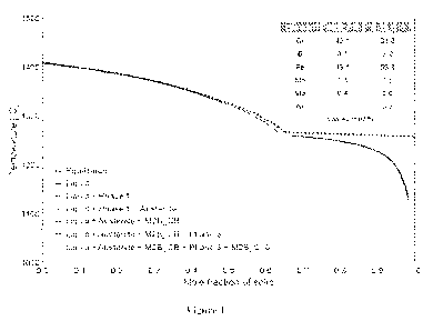
100651 Figure 1, Figure 2 and Figure 3 show Scheil solidification
diagrams for Alloys Al,
A3, and A4, respectively, calculated by Thermo-Calc software (Thermo-Calc
Software, Inc., version
2019a, TCFE9: TCS Steels/Fe-alloys Database, v9). The Scheil solidification
diagram is used
because it best represents rapid solidification that is experienced by the
powder when it is melted and
cooled during PBF printing. These diagrams and calculations suggest that
austenite forms early in
solidification followed by borides. Relatively rapid cooling of austenite
below the martensite start
temperature Ms causes austenite to transform to martensite. The Ms is
calculated from the
composition of the austenite phase and shown for Alloys Al, A3, and A4 in
Figure 4, Figure 5 and
Figure 6, respectively. Because the Ms for much of the austenite formed in
these alloys is above
room temperature, martensite is expected to form. The borides in Alloys Al,
A3, and A4, are
contemplated to be Cr-rich, V-rich, and W-rich, respectively. Although the
chemistry of these
borides evolves during solidification, a representative composition of each
boride phase is provided
in each figure That is, the figures identify the boride crystal structures as
M2B CB or M2B C16 or
MB B33 where M is reference to the particular metallic element present in
weight percent.
Reference to "phases" is a reference to other morphological solid states or
crystal structures that may
be present.
100661 Bars of each alloy with dimensions 1 cm x 1 cm x 1 cm, 6.7
cm x 1.4 cm x 1.4 cm,
and 7.4 cm x 2.5 cm x 0.6 cm were printed on a SLM28OHL laser PBF printer with
a pre-heat
temperature of 200 C. The laser power, velocity, hatch spacing, and layer
thickness used for each
alloy is presented in Table 2 and the powder size distribution used for each
alloy is presented in
Table 3.
Table 2
Print Parameter Al A2 A3 A4
Laser Power (W) 280 300 300 350
Laser Velocity (mm/s) 400 1000 1000
1200
Hatch Spacing (um) 100 120 100 100
Layer Thickness (um) 40 40 40 40
Energy Density (J/mm3) 175 63 75 73
Build Speed (cm3/hr) 5.8 17.3 14.4
17.3
13
CA 03183775 2022- 12- 21
WO 2021/262707
PCT/US2021/038464
Table 3
Alloy D10 (pm) D50 (run) D90 (run)
Al 17.3 28.4 45.5
A2 17.3 27.2 42.5
A3 15.9 24.6 38.1
A4 14.3 22.8 35.5
100671 X-ray diffraction (XRD) results of a bar made of Alloy Al
in Figure 7 indicate that
the microstructure is primarily martensite as predicted by the alloys design
and Thermo-Calc
calculations. The microstructures of these bars shown in Figure 8, 9 and 10
for Alloys Al, A3, and
A4, respectively, are dendritic, which is consistent with the segregation of
alloying elements to the
liquid during solidification and the formation of the borides towards the end
of solidification. The
darker phase decorating the dendrite perimeters is then presumably borides
while the interior of the
cells is the martensite.
100681 All printed bars are preferably free of cracks with
relatively low average porosity
ranging from 0.01% to 1.00%, as measured per ASTM E1245-03, which involves
optical image
analysis of a micrographic of a metallographic cross-section of the part. More
preferably, the parts
are such that there are no visible cracks present under a magnification of up
to 1000x over the
majority of the surface area of the part, such as 95% or more of the part
surface area. Accordingly,
this includes no visible cracks under a magnification of up to 1000X over 96%
or more, 97% or
more, 98% or more, 99% or more, or 100% of the part surface area. Figures 11,
12, 13 and 14 show
micrographs of the 1 cm x 1 cm x 1 cm bars of Alloys Al, A2, A3, and A4,
respectively as an
example of the typical porosity observed in each alloy.
100691 Table 4 lists the tensile properties, hardness, and
abrasion wear mass loss of the as-
built alloys listed in Table 1. The bars with dimensions 6.7 cm x 1.4 cm x 1.4
cm were tensile tested
in accordance with ASTM E8-16ael. The bars with dimensions 1 cm x 1 cm x 1 cm
were hardness
tested in accordance with ASTM E18-20. The bars with dimensions 7.4 cm x 2.5
cm x 0.6 cm were
abrasion wear tested in accordance with ASTM G65-16e1 Procedure A. Abrasion
wear resistance is
inversely related to the mass loss (i.e. a higher mass loss indicates less
wear resistance.) For
14
CA 03183775 2022- 12- 21
WO 2021/262707
PCT/US2021/038464
comparison, tensile properties, hardness, and abrasion wear mass loss of
conventional steels 316L,
M300, 17-4 PH, and H13 printed on an SLM28OHL printer are also provided. Note
that to print H13
without severe cracking, the powder bed needed to be pre-heated to 500 C.
Table 4
Yield Strength Tensile Elongation Hardness
Abrasion Wear
Alloy
(MPa) Strength (MPa) (%) (EIRC) Mass
Loss (g)
316L 432 634 58.1 <30
3.28
M300 1085 1176 19.1 37
2.89
17-4 PH 865 967 22.8 32
H13 927 1082 1.1 56
1.76
Al 56
1.80
A2 744 1187 0.3 53
2.10
A3 40
1.89
A4 755 1280 0.4 56
2.14
100701 The as-built hardness of Alloys Al, A2, and A4 are higher
than other alloys (316L,
M300, and 17-4PH) when they are printed on either a substrate, or previous
solidified layer, having a
temperature of 200 C. Alloy Al and A4 have the same hardness as as-built H13,
which was printed
at 500 C. Additionally, Alloys Al, A2, A3, and A4 have lower abrasion wear
mass loss, indicating
better wear resistance, than 316L and M300. Abrasion wear mass loss of Alloys
Al and A3 were
similar to that of H13, indicating similar wear resistance.
100711 Wear resistance in tool steels is often a function of
precipitate size and distribution.
The equilibrium phase diagrams generated by Thermo-Calc software for Alloys
Al, A3 and A4,
which are shown in Figure 15, Figure 16, and Figure 17 respectively, suggest
that at temperatures at
or above 1000 C, austenite with Ms above room temperature is formed and all
precipitates other
than borides dissolve, providing an opportunity to grow the boride phase in a
commercially relevant
temperature/time scale. As noted above, temperatures in the range of 900 C to
1200 C for 0,5 to
8.0 hours. The austenite has a calculated Ms of 165 C to 175 C and therefore
is expected to
transform to martensite by quenching the alloy after aging at these
temperatures, preserving the hard
CA 03183775 2022- 12- 21
WO 2021/262707
PCT/US2021/038464
martensitic matrix. Figure 18, Figure 19, and Figure 20 show the
microstructures of Alloy Al after
aging at 1100 "V for 2 hours, 4 hours, and 8 hours, respectively followed by a
gas quench, freeze at -
85 C for 2 hours, and temper at 175 C for 2 hours. This process is akin to a
quench and temper
typically used for martensitic tool steels. The dendritic microstructure
observed in the as-built state
in Figure 8 is no longer present, replaced by a homogenous structure
consisting of nominally round
borides in a martensitic matrix. The diameter of the borides increases with
aging time ranging from
0.1 microns to 1 micron after 2 hours and 1 micron to 4 microns after 8 hours.
It is contemplated
that the size of these borides can also be controlled by the temperature of
the aging step. Similar
microstructural evolution is observed in Alloy A3 in Figures 21 and 22,
respectively, after the same
heat treatment as Alloy Al with an aging time of 2 hours and 8 hours
respectively. Figure 23 shows
the microstructural evolution in Alloy A4 after the same heat treatment as
Alloy Al with an aging
time of 8 hours, respectively.
100721 Table 5 shows the tensile properties, hardness, and
abrasion wear mass loss of Alloys
Al, A2, A3, and A4 after heat treatment. Tensile properties, hardness, and
abrasion wear mass loss
were measured using the same methods used to record as-built values in Table
4. All tensile
properties and hardness for Alloys Al, A2, A3, and A4 were recorded on pieces
aged at 1100 C for
8 hours followed by a gas quench, freeze at -85 "V for 2 hours, and temper at
175 "V for 2 hours.
Abrasion wear mass loss for Alloys Al, A2, A3, and A4 were recorded on pieces
aged at 1100 C
for 2 hours followed by a gas quench, freeze at ¨ 85 C for 2 hours, and
temper at 175 C for 2
hours. For comparison, values of printed and heat treated M300, 17-4 PH, and
H13 are also
provided. The heat treatments done for these alloys were selected to maximize
hardness. M300 was
aged at 490 C for 6 hours after printing. 17-4 PH was heat treated in
accordance with ASTM
A564M H900 procedure after printing. H13 was heated at 1050 C for 0.5 hours,
quenched, and
tempered at 500 C for 2 hours. As noted above, and as confirmed by Table 5,
for a given printed
part having an initial set of properties in the as-built condition, namely
yield strength Yl, tensile
strength TS1, elongation El, HRC hardness HI and abrasion wear resistance WI
(mass loss in
grams via ASTM G65-16e1 Procedure A), after heat treatment, the properties
indicate a second
value for yield strength (YS2), tensile strength (TS2), elongation (E2), HRC
hardness (H2) and
abrasion wear resistance (W2). As can be seen from Table 5, the heat treated
part can be
characterized by any one or more of these secondary values that are observed
as follows: Y52>YS1,
16
CA 03183775 2022- 12- 21
WO 2021/262707
PCT/US2021/038464
TS2>TS1, E2 > El, H2 = H1 +1- 10 and W2 < Wl. More preferably, E2 is at least
5.0 % greater
than El and W2 is at least 0.5 lower in value than Wl.
[0073] More specifically, for Alloys Al, A2, A3, and A4, the heat
treatment increases the
yield strength, tensile strength, and elongation while decreasing the abrasion
wear mass loss (i.e.
increasing wear resistance) from the as-built state. In particular, after heat
treatment, the alloys
herein indicate an elongation of at least 5.0 %, a HRC hardness of at least 50
and abrasion wear
resistance (mass loss in grams via ASTM G65-16e1 Procedure A) of less than or
equal to 1.90. The
abrasion wear mass loss of Alloys Al, A2, and A3 is lower than that for all
conventional steels. The
hardness after heat treatment increases from the as-built state for Alloy A3
but decreases for Alloys
Al, A2, and A4. Nevertheless, the hardness of all new alloys remains at or
above 50 HRC. Because
the precipitate size and distribution can be controlled by aging time and/or
temperature, as shown for
Alloy Al in Figures 18, 19 and 20, it is contemplated that the wear resistance
can be tailored for a
specific application.
Table 5
Yield Strength Tensile Elongation Hardness
Abrasion Wear
Alloy
(MPa) Strength (MPa) (%) (FIRC) Mass
Loss (g)
316L N/A
M300 2101 2196 4.2 54
2.92
17-4 PH 770 965 13.8 41
2.75
H13 1481 1481 <0.1 58
1.48
Al 50
0.79
A2 1206 1630 7.8 51
1.29
A3 1275 1602 10.4 50
0.80
A4 1267 1713 5.5 51
1.90
[0074] The foregoing description of several methods and
embodiments has been presented
for purposes of illustration. It is not intended to be exhaustive of to limit
the claims to the precise
steps and/or forms disclosed.
17
CA 03183775 2022- 12- 21
WO 2021/262707
PCT/US2021/038464
10075] While exemplary embodiments are described above, it is not
intended that these
embodiments describe all possible forms of the invention. Rather, the words
used in the
specification are words of description rather than limitation, and it is
understood that various
changes may be made without departing from the spirit and scope of the
invention. Additionally, the
features of various implementing embodiments may be combined to form further
embodiments of
the invention.
18
CA 03183775 2022- 12- 21