Note: Descriptions are shown in the official language in which they were submitted.
WO 2022/005713
PCT/US2021/036522
CONCENTRIC CATHETER SYSTEM
B AC KGROUND
[0001] A catheter is commonly used to infuse fluids into vasculature
of a patient. For example,
the catheter may be used for infusing normal saline solution, various
medicaments, or total
parenteral nutrition. The catheter may also be used for withdrawing blood from
the patient.
[0002] The catheter may include an over-the-needle peripheral
intravenous ("IV") catheter. In
this case, the catheter may be mounted over an introducer needle having a
sharp distal tip. The
catheter and the introducer needle may be assembled so that the distal tip of
the introducer needle
extends beyond the distal tip of the catheter with the bevel of the needle
facing up away from skin
of the patient. The catheter and the introducer needle are generally inserted
at a shallow angle
through the skin into vasculature of the patient.
[0003] In order to verify proper placement of the introducer needle
and/or the catheter in the
blood vessel, a clinician generally confirms that there is "flashback" of
blood in a flashback
chamber of the catheter assembly. Once placement of the needle has been
confirmed, the clinician
may temporarily occlude flow in the vasculature and remove the needle, leaving
the catheter in
place for future blood withdrawal or fluid infusion.
[0004] Blood withdrawal using the catheter may be difficult for
several reasons, particularly
when a dwell time of the catheter within the vasculature is more than one day.
When the catheter
is left inserted in the patient for a prolonged period of time, the catheter
or vein may be more
susceptible to narrowing, collapse, kinking, blockage by debris (e.g., fibrin
or platelet clots), and
adhering of a tip of the catheter to the vasculature. Due to this, the
catheter may become
compromised for infusion, blood draw, or aspiration over time. The catheter is
often used for
-1 -
CA 03183976 2022- 12- 22
WO 2022/005713
PCT/US2021/036522
acquiring a blood sample at a time of catheter placement, but the catheter is
less frequently used
for acquiring a blood sample during the catheter dwell period. Therefore, when
a blood sample is
required, an additional needle stick is often used to provide vein access for
blood collection, which
may be painful for the patient and result in higher material costs.
[0005] The subject matter claimed herein is not limited to
embodiments that solve any
disadvantages or that operate only in environments such as those described
above. Rather, this
background is only provided to illustrate one example technology area where
some
implementations described herein may be practiced.
SUMMARY
[0006] The present disclosure relates generally to vascular access
systems and related devices
and methods. In some embodiments, a catheter system may facilitate
aspirations, blood draw, and
infusions by opening a fluid path through the catheter system while also
reducing a risk of
microbial ingress and dislodgement of the catheter system from vasculature of
a patient. In some
embodiments, the catheter system may include an outer catheter adapter, which
may include a
distal end and a proximal end. In some embodiments, the catheter system may
include an outer
catheter, which may include a distal end, a proximal end, an outer catheter
lumen extending
through the distal end of the outer catheter and the proximal end of the outer
catheter, and an inner
surface forming the outer catheter lumen. In some embodiments, the outer
catheter may extend
distally from the distal end of the outer catheter adapter, and the distal end
of the outer catheter
may include a distal opening.
[0007] In some embodiments, the catheter system may include an inner
catheter adapter, which
may include a distal end, a proximal end, and an inner catheter lumen
extending through the distal
end of the inner catheter adapter and the proximal end of the inner catheter
adapter. In some
-2-
CA 03183976 2022- 12- 22
WO 2022/005713
PCT/US2021/036522
embodiments, the inner catheter and the outer catheter may be concentric. In
some embodiments,
the inner catheter may extend distally from the distal end of the inner
catheter adapter, and the
inner catheter may be disposed within the outer catheter lumen. In some
embodiments, the inner
catheter and the inner catheter adapter may be configured to move with respect
to the outer catheter
and the outer catheter adapter between a proximal position and a distal
position. In some
embodiments, in response to the inner catheter and the inner catheter adapter
being in the distal
position, the distal end of the inner catheter may be disposed distal to the
distal end of the outer
catheter.
[0008] In some embodiments, the catheter system may include a gap
disposed between an outer
surface of the inner catheter and the inner surface of the outer catheter. In
some embodiments, in
response to the inner catheter and the inner catheter adapter being in the
distal position, the inner
catheter may be disposed within the distal opening to restrict flow distally
into the gap. In some
embodiments, in response to movement of the inner catheter from the distal
position to the
proximal position, the inner catheter may be disposed proximal to the distal
opening and the gap
may be in fluid communication with the distal opening.
[0009] In some embodiments, the inner catheter adapter may be
slidable relative to outer
catheter adapter to move the inner catheter adapter and the inner catheter
between the proximal
position and the distal position. In some embodiments, the catheter system may
include a toggle
joint, which may include a distal end coupled to the outer catheter adapter
and a proximal end
coupled to the inner catheter adapter. In some embodiments, the toggle joint
may be configured to
depress to move the inner catheter and the inner catheter adapter to the
proximal position.
[0010] In some embodiments, the inner catheter and the inner catheter
adapter may be
configured to move with respect to the outer catheter and the outer catheter
adapter between a first
-3-
CA 03183976 2022- 12- 22
WO 2022/005713
PCT/US2021/036522
position and a second position. In some embodiments, the catheter system may
include multiple
fenestrations disposed within the outer catheter or the inner catheter. In
some embodiments, the
fenestrations may be blocked when the inner catheter is in the first position.
In some embodiments,
in response to movement of the inner catheter from the first position to the
second position, the
fenestrations may be unblocked to allow fluid to flow through the
fenestrations into the inner
catheter lumen.
[0011] In some embodiments, the fenestrations may be disposed within
the outer catheter, and
the catheter system may include multiple other fenestrations disposed within
the inner catheter. In
some embodiments, the inner catheter and the inner catheter adapter may be
configured to rotate
with respect to the outer catheter and the outer catheter adapter between the
first position and the
second position. In some embodiments, in response to the inner catheter and
the inner catheter
adapter being in the second position, the fenestrations and the other
fenestrations may be aligned.
In some embodiments, in response to the inner catheter and the inner catheter
adapter being in the
first position, the fenestrations and the other fenestrations may be
misaligned.
[00121 In some embodiments, the inner catheter and the inner catheter
adapter may be
configured to slide with respect to the outer catheter and the outer catheter
adapter between the
first position and the second position. In some embodiments, in response to
the inner catheter being
in the second position, the inner catheter may extend through the distal
opening of the outer
catheter. In some embodiments, the fenestrations may be disposed within the
distal end of the inner
catheter. In these and other embodiments, the fenestrations may be disposed
distal to the distal
opening of the outer catheter in response to movement of the inner catheter
from the first position
to the second position.
-4-
CA 03183976 2022- 12- 22
WO 2022/005713
PCT/US2021/036522
[0013] In some embodiments, the fenestrations may be disposed within
the outer catheter, and
the other fenestrations may be disposed within the inner catheter. In these
and other embodiments,
in response to the inner catheter and the inner catheter adapter being in the
second position, the
fenestrations and the other fenestrations may be aligned, and in response to
the inner catheter and
the inner catheter adapter being in the first position, the fenestrations and
the other fenestrations
may be misaligned. In some embodiments, the fenestrations may be disposed
within the distal end
of the outer catheter or within the proximal end of the outer catheter.
[0014] In some embodiments, the inner catheter and the inner catheter
adapter may be
configured to slide with respect to the outer catheter and the outer catheter
adapter between the
first position and the second position. In these and other embodiments, the
fenestrations may be
disposed within the outer catheter, and in response to the inner catheter
moving between the first
position and the second position, the distal end of the inner catheter may
move distal to the
fenestrations.
[0015] In some embodiments, the catheter may include multiple
fenestrations within the wall.
In some embodiments, the catheter system may include a tube disposed within
the catheter. In
some embodiments, the tube may include a distal end and may be configured to
move between a
proximal position and a distal position. In some embodiments, in response to
the tube moving
between the proximal position and the distal position, the distal end of the
tube may move distal
to the fenestrations of the catheter.
[0016] In some embodiments, the distal end of the tube may include a
sharp edge. In some
embodiments, a proximal end of the tube may be coupled to a guidewire. In some
embodiments,
the catheter system may include an outer catheter, and the catheter may be an
inner catheter
disposed within the outer catheter. In these and other embodiments, the tube
may be disposed
-5-
CA 03183976 2022- 12- 22
WO 2022/005713
PCT/US2021/036522
within the inner catheter lumen. In some embodiments, the catheter system may
include the toggle
joint, which may include the distal end of the toggle joint coupled to the
catheter adapter and the
proximal end of the toggle joint coupled to the tube. In some embodiments, the
toggle joint may
be configured to depress to move the tube to the proximal position.
[0017] It is to be understood that both the foregoing general
description and the following
detailed description are examples and explanatory and are not restrictive of
the invention, as
claimed. It should be understood that the various embodiments are not limited
to the arrangements
and instrumentality illustrated in the drawings. It should also be understood
that the embodiments
may be combined, or that other embodiments may be utilized and that structural
changes, unless
so claimed, may be made without departing from the scope of the various
embodiments of the
present invention. The following detailed description is, therefore, not to be
taken in a limiting
sense.
BRIEF DESCRIPTION OF THE SEVERAL VIEWS OF THE DRAWINGS
[0018] Example embodiments will be described and explained with
additional specificity and
detail through the use of the accompanying drawings in which:
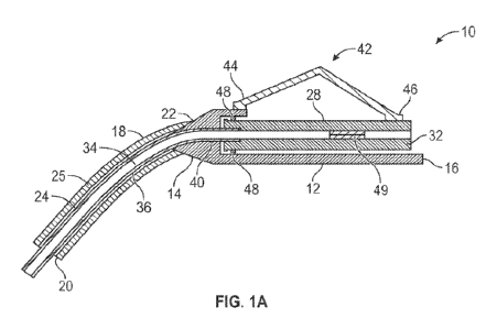
[0019] Figure lA is a cross-sectional view of an example catheter
system, illustrating an
example inner catheter and an example inner catheter adapter in an example
distal position,
according to some embodiments;
[0020] Figure 1B is a cross-sectional view of the catheter system,
illustrating the inner catheter
and the inner catheter adapter in an example proximal position, according to
some embodiments;
[0021] Figure 2A is a cross-sectional view of a portion of the
catheter system, illustrating the
inner catheter and the inner catheter adapter in the proximal position and an
example outer catheter,
according to some embodiments;
-6-
CA 03183976 2022- 12- 22
WO 2022/005713
PCT/US2021/036522
[0022] Figure 2B is a cross-sectional view of a portion of the
catheter system, illustrating the
inner catheter and the inner catheter adapter in the distal position,
according to some embodiments;
[0023] Figure 3 is an upper perspective view of the catheter system,
illustrating an example
toggle joint, according to some embodiments;
[0024] Figure 4A is an upper perspective view of the inner catheter
and the example inner
catheter adapter in the distal position, illustrating example fenestrations,
according to some
embodiments;
[0025] Figure 4B is an upper perspective view of the inner catheter
and the inner catheter
adapter of Figure 4A in the proximal position, illustrating the inner catheter
in the distal position,
according to some embodiments;
[0026] Figure 4C is an upper perspective view of the inner catheter
and the inner catheter
adapter in the distal position, illustrating other example fenestrations,
according to some
embodiments;
[0027] Figure 4D is an upper perspective view of the inner catheter
and the inner catheter
adapter of Figure 4C in the proximal position, according to some embodiments;
[0028] Figure 5 is a partial cutaway view of the catheter system,
illustrating example threading,
according to some embodiments;
[0029] Figure 6A is a cross-sectional view of a portion of the
catheter system, illustrating an
example tube in a proximal position, according to some embodiments;
[0030] Figure 6B is a cross-sectional view of a portion of the
catheter system, illustrating the
tube in a distal position, according to some embodiments; and
[0031] Figure 6C is a cross-sectional view of a portion of the
catheter system, illustrating the
tube with one or more slots, according to some embodiments.
-7-
CA 03183976 2022- 12- 22
WO 2022/005713
PCT/US2021/036522
DETAILED DESCRIPTION
[0032] As used in the present disclosure, the term "distal" refers to
a direction away from a
clinician who would place the device into contact with a patient, and nearer
to the patient. As used
in the present disclosure, the term -proximal" refers to a direction nearer to
the clinician who
would place the device into contact with the patient, and farther away from
the patient.
[0033] Referring now to Figures 1A-1B, in some embodiments, the
catheter system 10 may
include an outer catheter adapter 12, which may include a distal end 14 and a
proximal end 16. In
some embodiments, the catheter system 10 may include an outer catheter 18
which may include a
distal end 20, a proximal end 22, an outer catheter lumen 24 extending through
the distal end 20
of the outer catheter 18 and the proximal end 22 of the outer catheter 18, and
an inner surface 25
forming the outer catheter lumen 24. In some embodiments, the outer catheter
18 may extend
distally from the distal end 14 of the outer catheter adapter 12. In some
embodiments, the distal
end 20 of the outer catheter may include a distal opening 26.
[0034] In some embodiments, the catheter system 10 may further
include an inner catheter
adapter 28. In some embodiments, the inner catheter adapter 28 may include a
distal end 30, a
proximal end 32, and an inner catheter lumen 34 extending through a distal end
30 of the inner
catheter adapter 28 and the proximal end 32 of the inner catheter adapter 28.
In some embodiments,
an inner catheter 36 may extend distally from the distal end 30 of the inner
catheter adapter 28. In
some embodiments, the inner catheter 36 may be disposed within the outer
catheter lumen 24. In
some embodiments, the inner catheter 36 and the inner catheter adapter 28 may
be configured to
move with respect to the outer catheter 18 and the outer catheter adapter 12
between a proximal
position, illustrated, for example, in Figure 1A, and a distal position,
illustrated, for example, in
Figure 1B .
-8-
CA 03183976 2022- 12- 22
WO 2022/005713
PCT/US2021/036522
[0035] In some embodiments, in response to the inner catheter 36 and
the inner catheter adapter
28 being in the proximal position, as illustrated, for example, in Figure 1A,
a distal end 38 of the
inner catheter 36 may be disposed distal to the distal end 20 of the outer
catheter 18. In some
embodiments, in response to the inner catheter 36 and the inner catheter
adapter 28 being in the
distal position, as illustrated, for example. in Figure 1B, the distal end 38
of the inner catheter 36
may be disposed more distal to the distal end 20 of the outer catheter 18 than
in the proximal
position.
[0036] In some embodiments, the outer catheter 18 may be coupled to
the outer catheter adapter
12 via an interference fit, a bushing, an adhesive, or another suitable
technique or device. In some
embodiments, the inner catheter 36 may be coupled to the inner catheter
adapter 28 via an
interference fit, a bushing, an adhesive, or another suitable technique or
device.
[0037] In some embodiments, the inner catheter adapter 28 may be
slidable relative to the outer
catheter adapter 12 to move the inner catheter adapter 28 and the inner
catheter 36 between the
proximal position and the distal position. In some embodiments, the outer
catheter 18 may be
stationary within vasculature of a patient when the inner catheter 36 is
moved, and thus, not
dislodged from the vasculature in response to movement of the inner catheter
36.
[0038] In some embodiments, the catheter system 10 may include a
toggle joint 42 to facilitate
moving or sliding the inner catheter adapter 28 relative to the outer catheter
adapter 12, thereby
moving or sliding the inner catheter 36 relative to the outer catheter 18. In
some embodiments,
the toggle joint 42 may also reduce a risk of bacterial contamination by
allowing the user to contact
the toggle joint 42 instead of a particular catheter adapter to move the inner
catheter 36 within the
vasculature.
-9-
CA 03183976 2022- 12- 22
WO 2022/005713
PCT/US2021/036522
[0039] In some embodiment, the toggle joint 42 may include a distal
end 44 coupled to the
outer catheter adapter 12 and a proximal end 46 coupled to the inner catheter
adapter 28. In some
embodiments, the toggle joint 42 may be configured to depress to move the
inner catheter 36 and
the inner catheter adapter 28 to the proximal position. In some embodiments,
the toggle joint 42
may be depressed from a first position, illustrated, for example, in Figure
1A, to a second position,
illustrated, for example, in Figure 2B. In some embodiments, the toggle joint
42 may be more
angled in the first position than the second position. In some embodiments,
the toggle joint 42 may
be generally straight in the second position. In some embodiments, in response
to toggle no longer
being depressed, the toggle joint 42 may remain in the second position or the
toggle joint 42 may
return to the first position, which may move the inner catheter 36 and the
inner catheter adapter 28
to the distal position.
[0040] In some embodiments, the toggle joint 42 may be constructed of
a flexible polymer or
other suitable material. In some embodiments, the toggle joint 42 may be
configured to fold at a
groove or crease between the distal end 44 and the proximal end 46. In some
embodiments, the
toggle joint 42 may be resilient. In some embodiments, the flexible polymer or
other suitable
material may facilitate folding at the groove. In some embodiments, the toggle
joint 42 may be
monolithically formed as a single unit. In other embodiments, the toggle joint
42 may include
separate parts, which may be joined by one or more hinges.
[0041] In some embodiments, the inner catheter adapter 28 may be
disposed within or on top
of outer catheter adapter 12. In some embodiments, the outer catheter 18 may
include an inner
diameter greater than an outer diameter of the inner catheter 36 such that the
outer catheter 18 may
receive the inner catheter 36 therein.
-10-
CA 03183976 2022- 12- 22
WO 2022/005713
PCT/US2021/036522
[00421 In some embodiments, one or more seal elements 48, such as an
0-ring, for example,
may be disposed between the outer catheter adapter 12 and the inner catheter
adapter 28 to seal a
fluid path between the outer catheter adapter 12 and the inner catheter
adapter 28. In some
embodiments, the seal element 48 may include silicone, rubber, an elastomer,
or another suitable
material. In some embodiments, a lumen of the inner catheter adapter 28 may
include a septum 49
to prevent blood from flowing through the proximal end 32 of the inner
catheter adapter 28.
[0043] Referring now to Figures 2A-2B, the distal end 20 of the outer
catheter 18 and the distal
end 38 of the inner catheter 36 are illustrated, according to some
embodiments. In some
embodiments, the inner catheter adapter 28 may be moved in a proximal
direction relative to the
outer catheter adapter 12 to retract the inner catheter 36 or may be moved in
a distal direction
relative to the outer catheter adapter 12 to advance the inner catheter 36. In
some embodiments,
the toggle joint 42 (see Figures 1A-1B) may be used to move the inner catheter
36 as described
with respect to Figures 1A-1B. In some embodiments, a screw-type adjuster as
described, for
example, with respect to Figure 5, or another suitable mechanism may be used
to move the inner
catheter 36.
[0044] In some embodiments, in response to the inner catheter 36 and
the inner catheter adapter
28 being in the proximal position, as illustrated, for example, in Figure 2A,
the distal end 38 of the
inner catheter 36 may be disposed proximal to the distal opening 26 of the
outer catheter 18. In
some embodiments, in response to the inner catheter 36 and the inner catheter
adapter 28 being in
the distal position, as illustrated, for example, in Figure 2B, the distal end
38 of the inner catheter
36 may be disposed distal to the distal opening 26 of the outer catheter 18.
[0045] In some embodiments, a gap 50 may be disposed between an outer
surface of the inner
catheter 36 and an inner surface of the outer catheter 18. In some
embodiments, in response to the
-11 -
CA 03183976 2022- 12- 22
WO 2022/005713
PCT/US2021/036522
inner catheter 36 and the inner catheter adapter 28 being in the distal
position and/or the proximal
position, the gap 50 may be in fluid communication with the distal opening 26
of the outer catheter
18 such that in response to the outer catheter 18 being inserted into a vein,
blood may flow through
the distal opening 26 of the outer catheter 18 and into the gap 50. In some
embodiments, the gap
50 may be annular.
[0046] In some embodiments, in response to the inner catheter 36 and
the inner catheter adapter
28 being in the distal position, the inner catheter 36 may be disposed within
the distal opening 26
and restrict, partially or completely, flow distally into the gap 50. The
distal position is illustrated
in Figure 2B, according to some embodiments. In some embodiments, in response
to movement
of the inner catheter 36 from the distal position to the proximal position,
the inner catheter 36 may
be disposed proximal to the distal opening 26 and the gap 50 may be in fluid
communication with
the distal opening 26. The proximal position is illustrated in Figure 2A,
according to some
embodiments.
[0047] In some embodiments, the inner catheter 36 and/or the outer
catheter 18 may include
one or more fenestrations or holes, which may facilitate flow of fluid in or
out. In some
embodiments, a distal end of the inner catheter 36 may be closed, which may
prevent occlusion.
In some embodiments, the distal end of the inner catheter 36 may be rounded
and/or lubricated to
reduce a likelihood of damaging a vein.
[0048] In some embodiments, between therapies, contact between the
distal opening 26 and the
inner catheter 36 may reduce a risk of a clot or thrombus entering the gap 50.
In some
embodiments, the inner catheter 36 may be moved to the proximal position for
blood collection
and/or infusion. In some embodiments, the inner catheter 36 may move
proximally with respect to
the outer catheter 18 to the proximal position, which may facilitate
aspirations, blood draws, and
-12-
CA 03183976 2022- 12- 22
WO 2022/005713
PCT/US2021/036522
infusions by ensuring an open fluid path, while also reducing risk of
dislodgement of the outer
catheter 18, microbial contamination, or other complications.
[0049] Referring now to Figure 3, the catheter system 10 is
illustrated, according to some
embodiments. In some embodiments, the catheter system 10 may include a needle
hub 52, which
may be removably coupled to the outer catheter adapter 12. In some
embodiments. an introducer
needle 53 may be coupled to the needle hub 52 and may extend through the outer
catheter 18 and
the inner catheter 36. In some embodiments, the outer catheter adapter 12 may
include wings 54.
[0050] In some embodiments, the catheter system 10 may include an
extension tube 56, which
may include a distal end coupled the inner catheter adapter 28 and in fluid
communication with
the inner catheter lumen 34. In some embodiments, an adapter 58 may be coupled
to a proximal
end of the extension tube 56. In some embodiments, a fluid infusion device may
be coupled to the
adapter 58 to deliver fluid to the patient via the inner catheter 36, which is
inserted in the vein. In
some embodiments, a blood collection device may he coupled to the adapter 58
to withdraw blood
from the patient via the inner catheter 36, which may be inserted in the vein.
In some embodiments,
the extension tube 56 may extend through a slot of the outer catheter adapter
12. In some
embodiments, the catheter system 10 may not include the extension tube 56.
[0051] In some embodiments, the catheter system 10 may be vented to
observe blood flashback
and facilitate proximal flow of blood. In some embodiments, the catheter
system 10 may be vented
in any suitable manner. For example, a vent plug 60 may be coupled to the
adapter 58 during
insertion of the outer catheter 18 into the patient. In some embodiments, the
vent plug 60 may be
permeable to air but not to blood. In some embodiments, the inner catheter 36,
the inner catheter
adapter 28, the extension tube 56, the adapter 58, and the vent plug 60 may be
in fluid
communication.
-13-
CA 03183976 2022- 12- 22
WO 2022/005713
PCT/US2021/036522
[00521 Referring now to Figures 4A-4B, in some embodiments, the inner
catheter 36 and the
inner catheter adapter 28 may be configured to move with respect to the outer
catheter 18 and the
outer catheter adapter 12 between a first position, illustrated, for example,
in Figure 4A, and a
second position, illustrated, for example, in Figure 4B. In some embodiments,
the first position
and the second position may correspond to the distal position and the proximal
position,
respectively. In some embodiments, the toggle joint 42 (see Figures 1A-1B) may
be used to move
the inner catheter 36 as described with respect to Figures 1A-1B. In some
embodiments, a screw-
type adjuster as described, for example, with respect to Figure 5, or another
suitable mechanism
may be used to move the inner catheter 36.
[00531 In some embodiments, one or more fenestrations 62 may be
disposed within the outer
catheter 18. In some embodiments, the fenestrations 62 may be disposed within
the distal end 14
of the outer catheter 18. In some embodiments, the fenestrations 62 may be
configured to be
blocked by the inner catheter 36 when the inner catheter 36 is in the first
position. In some
embodiments, in response to movement of the inner catheter 36 from the first
position to the second
position, the fenestrations 62 may be unblocked to allow fluid to flow through
the fenestrations 62
into the inner catheter lumen 34.
[0054] In some embodiments, the inner catheter 36 and the inner
catheter adapter 28 may be
configured to slide with respect to the outer catheter 18 and the outer
catheter adapter 12 between
the first position and the second position. In some embodiments, the inner
catheter 36 and the inner
catheter adapter 28 may be configured to slide with respect to the outer
catheter 18 and the outer
catheter adapter 12 along an axis 63 (see, for example, Figure 3) aligned with
the outer catheter
18.
-14-
CA 03183976 2022- 12- 22
WO 2022/005713
PCT/US2021/036522
[0055] In some embodiments, one or more other fenestrations 64 may be
disposed within the
inner catheter 36. In some embodiments, in response to the inner catheter 36
and the inner catheter
adapter 28 being in the second position, the fenestrations 62 and the other
fenestrations 64 may be
aligned. In some embodiments, the other fenestrations 64 may be moved distally
or proximally to
align with the other fenestrations. Additionally or alternatively, the other
fenestrations may be
rotated to align with the other fenestrations.
[0056] In some embodiments, in response to the inner catheter 36 and
the inner catheter adapter
28 being in the first position, the fenestrations 62 and the other
fenestrations 64 may be misaligned.
In some embodiments, the alignment of the fenestrations 62 and the other
fenestrations 64 may
increase flow of fluid through the inner catheter lumen 34, and misalignment
of the fenestrations
62 and the other fenestrations 64 may prevent a thrombus or other obstruction
from entering the
inner catheter lumen 34. In some embodiments, an outer circumference of the
inner catheter 36
may be slightly less than an inner circumference of the outer catheter 18 such
that the inner catheter
36 may move with respect to the outer catheter 18 and/or fluid may not leak
between the inner
catheter 36 and the outer catheter 18. In some embodiments, the outer
circumference of the inner
catheter 36 may contact the inner circumference of the outer catheter 18 along
all or a portion of
the outer circumference.
[0057] Referring now to Figures 4C-4D, in some embodiments, in
response to the inner
catheter 36 being in the second position, the inner catheter 36 may extend
through the distal
opening 26 of the outer catheter 18. In some embodiments, the distal end 38 of
the inner catheter
36 may be open or closed. In some embodiments, the fenestrations 62 may be
disposed within the
distal end 38 of the inner catheter 36, and the fenestrations 62 may be
disposed distal to the distal
opening 26 of the outer catheter 18 in response to movement of the inner
catheter 36 from the first
-15-
CA 03183976 2022- 12- 22
WO 2022/005713
PCT/US2021/036522
position to the second position. In these embodiments, the fenestrations 62
may facilitate fluid
flow through the fenestrations and into the inner catheter lumen 34 without
including any
fenestrations within the outer catheter 18.
[0058] In some embodiments, the toggle joint 42 (see Figures IA-1B)
may be used to move the
inner catheter 36 as described with respect to Figures IA-1B. In some
embodiments, a screw-type
adjuster as described, for example, with respect to Figure 5, or another
suitable mechanism may
be used to move the inner catheter 36.
[0059] Referring now to Figure 5, in some embodiments, the inner
catheter 36 may be rotated
with respect to the outer catheter 18 via a user-controlled method. For
example, the catheter system
may include a screw-type adjustor 66. In some embodiments, the screw-type
adjustor 66 may
include threading 70, which may correspond to other threading 72. In some
embodiments, the
threading 70 may be disposed on an outer surface and/or the distal end 30 of
the inner catheter
adapter 28. In some embodiments, the other threading 72 may he disposed on an
inner surface of
the outer catheter adapter 12. In some embodiments, the inner catheter adapter
28 may be coupled
to the outer catheter adapter 12 via the threading 70 and the other threading
72.
[0060] In some embodiments, the inner catheter adapter 28 and inner
catheter 36 may rotate
about the axis 63, which may be aligned with the outer catheter 18 between the
first position and
the second position. In further detail, the inner catheter adapter 28 may be
threaded or unthreaded
with respect to the outer catheter adapter 12 from the first position to the
second position and/or
from the second position to the first position. In some embodiments, the outer
catheter adapter 12
may be stationary within the vasculature of the patient when the inner
catheter 36 is moved, and
thus, not dislodged from the vasculature in response to movement of the inner
catheter 36.
-16-
CA 03183976 2022- 12- 22
WO 2022/005713
PCT/US2021/036522
[0061] Referring now to Figures 6A-6C, in some embodiments, a tube 80
may be disposed
within the outer catheter 18. In some embodiments, the tube 80 may correspond
to the inner
catheter 36. In other embodiments, the tube 80 may be coupled to a guidewire
82, which may be
used to advance the tube 80 distally and/or retract the tube 80 proximally.
[0062] In some embodiments, the outer catheter 18 may include the
fenestrations 62 through a
wall of the outer catheter 18. In some embodiments, in response to the tube 80
moving between a
proximal position, illustrated, for example, in Figure 6A, and a distal
position, illustrated, for
example, in Figure 6B, a distal end 84 of the tube 80 may contact and/or move
distal to the
fenestrations 62.
[0063] In some embodiments, a thrombus, clot or obstruction may block
one or more of the
fenestrations 62. In some embodiments, the distal end 84 of the tube 80 may
cut or perforate the
thrombus, clot, or obstruction to clear the fenestrations 104 and facilitate
fluid flow there through.
In some embodiments, the distal end 84 of the tube 80 may include a sharp edge
86. In some
embodiments, the sharp edge 86 may be annular. In some embodiments, the sharp
edge 86 may
include metal, ceramic, high density polyethylene, or another suitable
material. In some
embodiments, the sharp edge 86 may clear the fenestrations with axial motion
of the tube between
the proximal position and the distal position (which may be accomplished by
the user).
[0064] As illustrated in Figures 6C, in some embodiments, the tube 80
may include one or more
slots 92, which may extend from the distal end 84 of the tube 80. In some
embodiments, the slots
92 may include sharp edges 94, which may facilitate clearing the fenestrations
62 in response to
the tube 80 and the guidevvire 82 being rotated around the axis 63 (which may
be accomplished by
the user). In some embodiments, a width of each of the slots 92 may be greater
than or equal to a
width of the fenestrations 62.
-17-
CA 03183976 2022- 12- 22
WO 2022/005713
PCT/US2021/036522
[00651 All examples and conditional language recited herein are
intended for pedagogical
objects to aid the reader in understanding the invention and the concepts
contributed by the
inventor to furthering the art and are to be construed as being without
limitation to such specifically
recited examples and conditions. Although embodiments of the present
inventions have been
described in detail, it should be understood that the various changes,
substitutions, and alterations
could be made hereto without departing from the spirit and scope of the
invention.
-18-
CA 03183976 2022- 12- 22