Note: Descriptions are shown in the official language in which they were submitted.
WO 2022/006294
PCT/US2021/039927
FLUID SAMPLE COLLECTION CONTAINER
WITH CAP AND REMOVAL TOOL FOR FINGER GRIP LUER ADAPTER
CROSS-REFERENCE TO RELATED APPLICATION
[0001] The present application claims priority to United States Provisional
Application Serial
No. 63/047,063, entitled "Fluid Sample Collection Container with Cap and
Removal Tool for
Finger Grip Luer Adapter", filed July 1, 2020, the entire disclosure of which
is hereby incorporated
by reference in its entirety.
BACKGROUND
Field of the Disclosure
[0002] The present disclosure relates generally to a container assembly for
collecting a fluid
specimen. More particularly, the present disclosure relates to a container
assembly including a
combined finger grip luer adapter (FGLA) cap and removal tool.
Description of the Related Art
[0003] To conduct laboratory testing on biological fluid samples such as
urine, it is necessary
to provide a container for collecting the fluid sample. These collection
containers typically include
a cup-shaped container with a removable lid. Once a fluid sample has been
collected in the
container, the lid is reapplied. The collection container may then be
transported to a laboratory or
other testing facility where a sample of the collected specimen is extracted
for test purposes.
[0004] To simplify the sample extraction process, prior collection containers
have used lids
which not only cover and seal the collection container, but also provide for
the use of an extraction
device which permits the extraction of a sample of the fluid specimen. Such
lids may include a
receptable or cavity which supports a tube extending within the cavity to the
lower end of the cup-
shaped container in fluid communication with the specimen contained within the
container. The
tube or the lid may include an elongated receptacle housing a cannula and
needle so that an air-
evacuated collection device (e.g., a specimen collection tube) may be attached
thereto to draw a
portion of the collected sample thereinto without the need for removal of the
lid. In such
configurations, the sample can be removed without spilling or contaminating
the sample and/or
1
CA 03183985 2022- 12- 22
WO 2022/006294
PCT/US2021/039927
cavity area. Subsequent samples may be drawn from the collection container by
using a plurality
of collection tubes.
[0005] However, in prior collection containers, the cannula is provided within
the elongated
receptacle in the form of a finger grip luer adapter (FGLA) that is non-
removably integrated into
the container lid. Thus, when the user has completed all sample collection(s)
and wishes to dispose
of the container assembly, the entire removable lid must be disposed of in an
appropriate sharps
container or sharps biohazard container. Due to their large volume, removable
lids will quickly
fill the sharps container, necessitating frequent service by a qualified
disposal firm to safely handle
the sharps and/or biohazard waste. As such disposal services are far more
expensive than
conventional waste disposal services, health care providers generally seek to
minimize the
accumulated volume of sharps and/or biohazard waste.
[0006] Additionally, due to the FGLA being integrated into the lid, the
patient and/or healthcare
worker may be more at risk of needle-stick injuries during sample collection,
transport, and/or
disposal.
SUMMARY
[0007] In view of the foregoing, there exists a need for a fluid sample
collection container
having a reduced volume of sharps waste and which protects users and/or
healthcare workers from
potential needle-stick injuries.
[0008] In accordance with an embodiment of the present invention, a container
assembly for
collecting a fluid specimen includes a collection container defining a chamber
for receiving the
fluid specimen, and a container lid couplable to an open end of the collection
container to at least
partially close the open end thereof. The container assembly also includes an
elongate receptacle
extending from the container lid into the chamber of the collection container
when the container
lid is coupled to the open end of the collection container, the elongate
receptacle having an open
end portion defined within the container lid and configured to receive a
specimen collection tube
therein. The container assembly also includes a finger grip luer adapter
removably coupled to the
container lid within the elongate receptacle, with the finger grip luer
adapter including a needle
extending therefrom. The container assembly further includes an elongate cap
removably coupled
to the finger grip luer adapter and configured to extend over at least the
needle of the finger grip
2
CA 03183985 2022- 12- 22
WO 2022/006294
PCT/US2021/039927
luer adapter, wherein an upper portion of the elongate cap extends above at
least a portion of the
open end portion of the elongate receptacle when coupled to the finger grip
luer adapter.
[0009] In certain configurations, the upper portion of the elongate cap
include a finger grip
portion, and the finger grip portion is configured to extend above an upper
surface of the container
lid when coupled to the finger grip luer adapter. The finger grip portion may
include a ribbed or
textured surface so as to improve a user's grip on the finger grip portion of
the elongate cap. The
elongate cap may include an elongate portion and a cavity, wherein the cavity
extends from an
open end on a distal end of the elongated portion. The distal end of the
elongated portion of the
elongate cap may be configured to slip-fittingly or press-fittingly couple to
an upper portion of the
finger grip luer adapter.
[0010] In certain embodiments, the upper portion of the finger grip luer
adapter includes a
ribbed or textured surface. In other configurations, the lower portion of the
finger grip luer adapter
is configured to be removably coupl able to the elongate receptacle of the
container lid. The lower
portion of the finger grip luer adapter may include external threads, and the
external threads may
be configured to mate with a corresponding internal thread portion of the
elongate receptacle. The
finger grip luer adapter may be threadingly coupled to the container lid.
[0011] In other configurations, the finger grip luer adapter is
removable from the container lid
by way of counterclockwise rotation of the elongate cap when the elongate cap
is coupled to the
finger grip luer adapter. At least one of the collection container and the
container lid are formed of
a polymeric resin. Optionally, the elongate cap is formed of a polymeric
resin.
[0012] In accordance with a further embodiment of the present invention, a
container lid
assembly for use with a container assembly for collecting a fluid specimen,
includes an elongate
receptacle having an open end portion defined within the container lid and
configured to receive a
specimen collection tuber therein. The container lid assembly also includes a
finger grip luer
adapter removably coupled to the container lid within the elongate receptacle,
the finger grip luer
adapter comprising a needle extending therefrom, and an elongate cap removably
coupled to the
finger grip luer adapter. The elongate cap is configured to extend over at
least the needle of the
finger grip luer adapter, in which an upper portion of the elongate cap
extends above at least a
portion of the open end portion of the elongate receptacle when coupled to the
finger grip luer
adapter.
3
CA 03183985 2022- 12- 22
WO 2022/006294
PCT/US2021/039927
[0013] In certain configurations, the distal end of the elongate cap is
configured to slip-fittingly
or press-fittingly couple to an upper portion of the finger grip luer adapter.
The upper portion of
the finger grip luer adapter may include a ribbed or textured surface. The
lower portion of the
finger grip luer adapter may be configured to be removably couplable to the
elongate receptacle
of the container lid. Optionally, the lower portion of the finger grip luer
adapter may include
external threads, which are configured to mate with a corresponding internal
thread portion of the
elongate receptacle. The finger grip luer adapter may be removable from the
container lid by way
of counterclockwise rotation of the elongate cap when the elongate cap is
coupled to the finger
grip luer adapter.
[0014] In accordance with yet another embodiment of the present invention, a
method of
forming a container assembly for collecting a fluid specimen includes
providing a collection
container defining a chamber for receiving the fluid specimen. The method also
includes providing
a container lid couplable to the collection container, wherein the container
lid comprises an
elongate receptacle having an open end portion defined within the container
lid and configured to
receive a specimen collection tube therein. The method also includes coupling
a finger grip luer
adapter to the container lid within the elongate receptacle, the finger grip
luer adapter having a
needle extending therefrom. The method further includes coupling an elongate
cap to the finger
grip luer adapter such that the elongate cap extends over at least the needle
of the finger grip luer
adapter, wherein an upper portion of the elongate cap extends above at least a
portion of the open
end portion of the elongate receptacle when coupled to the finger grip luer
adapter.
[0015] In certain configurations, the method further requires that the finger
grip luer adapter is
threadingly coupled to the elongate receptacle of the container lid.
[0016] Further details and advantages of the present disclosure will be
understood from the
following detailed description read in conjunction with the accompanying
drawings.
BRIEF DESCRIPTION OF THE DRAWINGS
[0017] FIG. 1 is a perspective view of a fluid sample collection container
assembly in
accordance with an aspect of the present disclosure;
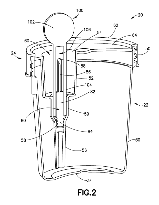
[0018] FIG. 2 is a cross-sectional view of the fluid sample collection
container assembly having
a FGLA cap and removal tool in accordance with an aspect of the present
disclosure;
4
CA 03183985 2022- 12- 22
WO 2022/006294
PCT/US2021/039927
[0019] FIG. 3A is a perspective view of the fluid sample collection container
assembly and
FGLA cap and removal tool in a first use configuration;
[0020] FIG. 3B is a perspective view of the fluid sample collection container
assembly and
FGLA cap and removal tool in a second use configuration;
[0021] FIG. 3C is a perspective view of the fluid sample collection container
assembly and
FGLA cap and removal tool in a third use configuration;
[0022] FIG. 3D is a perspective view of the fluid sample collection container
assembly and
FGLA cap and removal tool in a fourth use configuration; and
[0023] FIG. 4 is a cross-sectional perspective view of a container lid
assembly for use with a
fluid sample collection container assembly, FGLA cap and removal tool in
accordance with
another aspect of the disclosure.
DESCRIPTION OF THE INVENTION
[0024] The following description is provided to enable those skilled in the
art to make and use
the described aspects contemplated for carrying out the invention. Various
modifications,
equivalents, variations, and alternatives, however, will remain readily
apparent to those skilled in
the art. Any and all such modifications, variations, equivalents, and
alternatives are intended to
fall within the spirit and scope of the present invention.
[0025] For the purposes of the description hereinafter, the terms "upper",
"lower", "right",
"left", "vertical", "horizontal", "top", "bottom", "lateral", "longitudinal",
and derivatives thereof
shall relate to the invention as it is oriented in the drawings. However, it
is to be understood that
the invention may assume various alternative variations, except where
expressly specified to the
contrary. It is also to be understood that the specific devices illustrated in
the attached drawings,
and described in the following specification, are simply exemplary aspects of
the invention.
Hence, specific dimensions and other physical characteristics related to the
aspects disclosed
herein are not to be considered as limiting.
[0026] Referring to FIG. 1, a fluid sample collection container assembly 20 in
accordance with
an aspect of the present disclosure is shown. Fluid sample collection
container assembly 20
includes a collection container 22 and a container lid 24. An exemplary
collection container
CA 03183985 2022- 12- 22
WO 2022/006294
PCT/US2021/039927
assembly 20 in accordance with the present disclosure may be used to safely
collect a fluid
specimen (e.g., urine), transport the fluid specimen, and draw a sample of the
fluid specimen.
[0027] In one embodiment, collection container 22 and container lid
24 may be formed from
any conventional material such as, e.g., a polymeric resin. Polymeric resins
are well known in the
art and include, for example, polyethylene, polycarbonate, polystyrene, and
similar polymeric
resinous materials. However, it is to be understood that collection container
22 and/or container
lid 24 may be formed of other appropriate materials, and may be formed of
different materials.
[0028] Collection container 22 generally includes a sidewall 30 extending
between a first, open
end (not shown) and a second, closed end 34. Sidewall 30 defines an interior
chamber for receiving
a fluid specimen such as, e.g., urine. In one embodiment, sidewall 30 of
collection container 22
comprises a slightly tapering, tubular vessel having continuous, tapered
sidewalls 30. In one
embodiment, the collection chamber of container 22 is suitable for holding
biologically hazardous
materials. In one embodiment, sidewall 30 of collection container 22 may
include at least one fill
level indicator which identifies a fluid level of a collected fluid specimen.
[0029] Container lid 24 generally includes a flange 50 extending
around its outer rim, with
flange 50 being sized to provide a tight fit upon the collection container 22
when container lid 24
is placed over the first, open end of collection container 22. In one
embodiment, container lid 24
includes a generally disc-shaped component having an outer or peripheral zone
62 and an inner or
central zone 64. Flange 50 extends downward from peripheral zone 62 of
container lid 24. As is
shown in FIG. 2, flange 50 includes an inner surface which includes a means or
mechanism for
sealingly engaging container lid 24 with the collection container 22. In one
embodiment, flange
50 includes an interior threaded portion, thereby enabling container lid 24 to
be threadingly
connectable to a corresponding exterior threaded portion of the collection
container 22. In other
embodiments, the sealing portion of container lid 24 may include a snap fit
mechanism, a ball
detent, an interference fit mechanism, locking tabs, a spring loaded locking
mechanism, a latch, or
other similar mechanism to sealingly engage container lid 24 to collection
container 22, thereby
substantially preventing a fluid specimen contained within collection
container 22 and container
lid 24 from leaking out, while also preventing contaminants from entering.
[0030] Referring to FIG. 2, container lid 24 also includes an elongate
receptacle 52 extending
from the central zone 64 into collection container 22 and towards the second,
closed end 34 of
collection container 22. Receptacle 52 includes an open end portion 54 and an
opposing lower
6
CA 03183985 2022- 12- 22
WO 2022/006294
PCT/US2021/039927
end portion 56, with a receiving cavity 60 defined therein. In one embodiment,
receiving cavity
60 is sized and shaped to receive a specimen collection tube such as, e.g., an
evacuated tube (not
shown). In this way, a fluid specimen within collection container 22 can be
transferred to the
specimen collection tube without the need to remove container lid 24.
[0031] Referring still to FIG_ 2, a finger grip luer adapter (FGLA) 80 is
positioned within a
central portion 59 of the receptacle 52. Specifically, FGLA 80 includes an
upper portion 82 and a
lower portion 84. Upper portion 82 is configured to extend upward toward
receiving cavity 60
and may include ribbed or textured outer sidewalls. On the other hand, in one
embodiment, lower
portion 84 includes external threads, which are configured to mate with a
corresponding internal
thread portion 58 of the receptacle 52. In this way, the FGLA 80 may be
removably secured to
the receptacle 52 via a threaded interface. Alternatively, in another
embodiment, FGLA 80 may
be removably secured to receptacle 52 by way of a press-fit or slip-fit
connection.
[0032] Additionally, FGLA 80 includes a needle 86 extending upward from upper
portion 82
and into the receiving cavity 60. In one embodiment, a retractable sleeve 88
may extend over
needle 86. While not shown, needle 86 is configured to pierce the stopper of a
specimen collection
tube that is inserted into receptacle 52 by a user. In this way, a fluid
specimen may be drawn from
the collection container 22 into the specimen collection tube through the
lower end portion 56 of
receptacle 52 and FGLA 80, thereby enabling the user to collect the fluid
specimen without
necessitating removal of the container lid 24 from collection container 22.
[0033] FIG. 2 further shows a combined FGLA cap and removal tool 100 in
accordance with an
aspect of the present disclosure. As will be described in detail hereinbelow,
FGLA cap and
removal tool 100 serves the dual purpose of protecting all users from needle-
stick injuries and
substantially reducing sharps waste when the fluid sample collection container
assembly 20 is to
be discarded.
[0034] In one embodiment, FGLA cap and removal tool 100 includes a finger grip
portion 102.
Finger grip portion 102 is configured to extend outside of the receiving
cavity 60 and above the
central zone 64 of container lid 24 to allow for easy access by the user.
Additionally, in one
embodiment, the finger grip portion 102 may be ribbed, textured, or otherwise
treated so as to
improve the user's hold on the finger grip portion 102. The FGLA cap and
removal tool 100 may
be formed of any appropriate material or materials such as, e.g., a polymeric
resin. Examples of
polymeric resins include, e.g., polyethylene, polycarbonate, polystyrene, and
similar polymeric
7
CA 03183985 2022- 12- 22
WO 2022/006294
PCT/US2021/039927
resinous materials. However, it is to be understood that FGLA cap and removal
tool 100 may be
formed of other appropriate materials, and may be formed of two or more
different materials.
[0035] FGLA cap and removal tool 100 also includes an elongated bottom portion
104. A distal
end of the elongated portion 1104 is open, and a cavity 1106 is formed within
the elongated portion
104_ The cavity 106 extends from the open end of elongated portion 104 toward
the finger grip
portion 102. As is shown in FIG. 2, a lower section of cavity 106 of elongated
portion 104 is
configured to be slip-fit or press-fit over the upper portion 82 of FGLA 80
such that the elongated
portion 104 is removably secured to upper portion 82 of FGLA 80. As disclosed
above, the upper
portion 82 may include ribbed or textured outer sidewalls, which may aid in
providing a secure
interface between the FGLA 80 and the FGLA cap and removal tool 100.
Additionally and/or
alternatively, the inner sidewall of elongated portion 104 may also be ribbed
or textured.
Furthermore, in another embodiment, the lower section of cavity 106 of
elongated portion 104
may include a threaded portion configured to mate with a complimentary
threaded portion on the
upper portion 82 of the FGLA 80.
[0036] As is shown in FIG. 2, the cavity 106 is sized so as extend over the
needle 86 of FGLA
80. In this way, when FGLA cap and removal tool 100 is in position on FGLA 80,
the FGLA cap
and removal tool 100 acts to protect all users (e.g., patients and healthcare
workers) from potential
needle stick injuries, as needle 86 is completely enclosed within cavity 106.
As the FGLA cap
and removal tool 100 is slip-fit or press-fit onto FGLA 80, the user can
remove the FGLA cap and
removal tool 100 by applying an upward pulling force via the finger grip
portion 102. Conversely,
the user can replace the FGLA cap and removal tool 100 over the FGLA 80 by
applying a
downward pushing force via the finger grip portion 102.
[0037] However, while FGLA cap and removal tool 100 may be slid onto (or
removed from)
FGLA 80 via axial force relative to the FGLA 80, the interface between lower
section of cavity
106 of elongated portion 104 and the upper portion 82 of FGLA 80 is
sufficiently constricted so
as to transfer rotational force applied by the user via finger grip portion
102 onto the FGLA 80.
That is, if the user rotates the FGLA cap and removal tool 100 in a
counterclockwise direction,
lower portion 84 of FGLA 80 will unthread from internal thread portion 58 of
receptacle 52. As
the user continues to rotate the FGLA cap and removal tool 100, the FGLA 80
will eventually
disconnect entirely from receptacle 52, leaving the FGLA 80 secured to only
the FGLA cap and
removal tool 100. In this way, the FGLA 80 (and the incorporated needle 86)
are separable from
8
CA 03183985 2022- 12- 22
WO 2022/006294
PCT/US2021/039927
the container lid 24, with the needle 86 being enclosed within the elongated
bottom portion 104 of
FGLA cap and removal tool 100.
[0038] Once removed, the user may then dispose of both the FGLA cap and
removal tool 100
and the attached FGLA 80 in an appropriate sharps container or sharps
biohazard container. As
discussed above, conventional container lids typically used in specimen
extraction via evacuated
tubes include a finger grip luer adapter (FGLA) that is non-removably
integrated into the container
lid. Thus, the entire lid assembly must be disposed of within a sharps
container or sharps biohazard
container. However, in accordance with embodiments of the present disclosure,
only the FGLA
cap and removal tool 100 and removable FGLA 80 need be disposed of in a sharps
container or
sharps biohazard container, thereby greatly reducing the volume (and
subsequent cost) of sharps
waste, as the container lid 24 and collection container 22 may be disposed of
separately as standard
medical waste.
[0039] Referring to FIGS. 3A-3D, various in-use views of fluid sample
collection container
assembly 20 in accordance the present disclosure are shown. FIG. 3A
illustrates fluid sample
collection container assembly 20 prior to or after fluid sample collection,
wherein FGLA cap and
removal tool 100 is positioned on the needle and FGLA (not shown). In this
way, the FGLA cap
and removal tool 100 protects all users from the needle housed within the
receiving cavity 60 of
container lid 24.
[0040] Referring to FIG. 3B, when the user wishes to the expose the needle and
FGLA within
receiving cavity 60 in order to collect a fluid sample via, e.g., an evacuated
tube, the FGLA cap
and removal tool 100 may be pulled upward, thereby releasing the slip-fit or
press-fit connection
between the FGLA and the elongated portion 104. After collection of the fluid
sample, the FGLA
cap and removal tool 100 may be returned to the position shown in FIG. 3A.
[0041] When all necessary fluid sample(s) have been collected from the
collection container 22
and the user wishes to discard of the fluid sample collection container
assembly 20, the user may
rotate the FGLA cap and removal tool 100 in a counter-clockwise direction, as
is shown in FIG.
3C. As described above, such rotation allows for the separation of the FGLA
from the container
lid 24, with the needle of the FGLA still being protected within the elongated
portion 104 of the
FGLA cap and removal tool 100, as is shown in FIG. 3D. The user may then
discard of the
combined FGLA cap and removal tool 100 and FGLA into an appropriate sharps
container or
9
CA 03183985 2022- 12- 22
WO 2022/006294
PCT/US2021/039927
sharps biohazard container, while the remaining portions of the fluid sample
collection container
assembly 20 (i.e., the collection container 22 and the container lid 24) may
be disposed of in a
standard medical waste container.
[0042] Next, referring to FIG. 4, a container lid assembly 200 for use with a
fluid sample
collection container assembly in accordance with another aspect of the present
disclosure is shown.
In the embodiments described above with respect to FIGS. 2-3D, the fluid
sample collection
container assembly 20 included an FGLA cap and removal tool 100 that at least
partially extends
above a top surface 64 of the container lid 24, thereby enabling the user to
grip the FGLA cap and
removal tool 100 without reaching into the receiving cavity 60. However, in
the embodiment
shown in FIG. 4, container lid assembly 200 includes a FGLA cap and removal
tool 202, the
uppermost point of which extends below a top surface 204 of the container lid
assembly 200.
[0043] Referring still to FIG. 4, the container lid assembly 200 includes an
elongate receptacle
211, which is configured to extend into a collection container (not shown). An
opening 212 is
formed in the top surface 204 of the container lid assembly 200 above the
elongate receptacle 211,
while a lower portion 213 extends below the elongate receptacle 211. While not
shown in FIG. 4,
is to be understood that the lower portion 213 may be configured to receive a
finger grip luer
adapter (FGLA), similar to FGLA 80 shown and described with respect to FIG. 2,
with the FGLA
cap and removal tool 202 configured to extend over portions of the FGLA to
protect from needle
stick injuries and/or enable removal of the FGLA without needle exposure.
[0044] Elongate receptacle 211 includes cut-out portions 208 at an upper end
portion thereof,
with the cut-out portions 208 defining an open end portion 214 accessible to
the fingers of the user.
When installed, an upper portion of the FGLA cap and removal tool 202 extends
within an upper
receiving cavity 205 and above at least a portion of the open end portion 214,
while a lower portion
of the FGLA cap and removal tool 202 extends within a lower receiving cavity
206, which lies
below the open end portion 214. The upper receiving cavity 205 is defined
between the opening
212 and a juncture 210 of the elongate receptacle 211, while the lower
receiving cavity 206 is
defined between the juncture 210 and the lower surface of the elongate
receptacle 211. When
combined, the upper receiving cavity 205 and lower receiving cavity 206 are
sized and shaped to
receive a specimen collection tube such as, e.g., an evacuated tube (not
shown). In this way, a
fluid specimen within the collection container can be transferred to the
specimen collection tube
without the need to remove container lid assembly 200.
CA 03183985 2022- 12- 22
WO 2022/006294
PCT/US2021/039927
[0045] Due to the cut-out portions 208 formed in the container lid assembly
200, the FGLA cap
and removal tool 202 need not include a gripping portion which extends above
the top surface 204
in order for a user to access the FGLA cap and removal tool 202. However,
because the needle of
the FGLA is housed within the lower receiving cavity 206 of the elongate
receptacle 211, the user
is substantially protected from needle stick injuries when installing or
removing the FGLA cap
and removal tool 202.
[0046] While several embodiments of a fluid sample collection container
assembly are shown
in the accompanying figures and described hereinabove in detail, other
embodiments will be
apparent to, and readily made by, those skilled in the art without departing
from the scope and
spirit of the invention. For example, it is to be understood that this
disclosure contemplates, to the
extent possible, that one or more features of any embodiment can be combined
with one or more
features of any other embodiment. Accordingly, the foregoing description is
intended to be
illustrative rather than re stri cti ye.
I I
CA 03183985 2022- 12- 22