Note: Descriptions are shown in the official language in which they were submitted.
WO 2022/005922
PCT/US2021/039286
OFFSET ATTACHMENT DEVICE
FIELD OF THE INVENTION
The present invention relates generally to mechanical fasteners, and, more
particularly, to
attachment devices that utilize shafts to provide fixation.
BACKGROUND OF THE INVENTION
A bolt is a mechanical fastener with a threaded shaft and a head at one end.
Bolts are closely
related to screws and studs, which are also mechanical fasteners with threaded
shafts. These types
of threaded fasteners are typically inserted through two objects with aligned
holes in order to fixate
one object to the other. The holes of the two objects may be smooth or
internally threaded. If
internally threaded, the bolt may threadably engage with these internal
threads to facilitate the
fixation. Without the internal threads, the bolt may be made to engage with a
separate nut.
Bolts rely on axial forces causing sufficient friction at the threads to
remain in place. A
torque is applied to the head to generate this axial force. The force acts
between the bolt head and
whatever the bolt is screwed into, whether that is a nut or one of the objects
being fastened. This
causes elongation of the bolt and forces one object against the other.
While threaded fasteners are ubiquitous, they require that two objects being
fixated to one
another have aligned holes. Nevertheless, it is commonplace at worksites to
find objects that
require fixation to be somewhat misaligned. Such misalignment can result from
error or a failure
to adhere to necessary tolerances. When facing such a situation, it may be
necessary to modify
the objects being fixated (e.g., by elongating or drilling new holes) or to
disassemble a structure
and start over while being more careful. Both solutions are far from ideal.
As a result, there is a need for attachment devices that address the above-
described
deficiencies.
SUMMARY OF THE INVENTION
Embodiments of the present invention address the above-identified needs by
providing
attachment devices that may be used to attach one object to another with an
offset between the two
objects that is defined by the attachment device.
In accordance with an aspect of the invention, an apparatus comprises a
flange, an upper
shaft, and a lower shaft. The flange defines an upper surface and a lower
surface. The upper shaft
projects from the upper surface and is centered about an upper longitudinal
axis. The lower shaft
1
CA 03184245 2022- 12- 23
WO 2022/005922
PCT/US2021/039286
projects from the lower surface and is centered about a lower longitudinal
axis. The upper
longitudinal axis is not collinear with the lower longitudinal axis.
BRIEF DESCRIPTION OF THE DRAWINGS
These and other features, aspects, and advantages of the present invention
will become
better understood with regard to the following description, appended claims,
and accompanying
drawings where:
FIG. 1 shows a first attachment device in accordance with a first illustrative
embodiment
of the invention;
FIGS. 2-4 show a partially-exploded perspective view, a fully-exploded
perspective view,
and a sectional view, respectively, of an exemplary application involving the
FIG. 1 attachment
device;
FIGS. 5 and 6 show a perspective view and a sectional view, respectively, of a
second
attachment device in accordance with a second illustrative embodiment of the
invention;
FIGS. 7 and 8 show a perspective view and a sectional view, respectively, of a
third
attachment device in accordance with a third illustrative embodiment of the
invention;
FIGS. 9 and 10 show a perspective view and a sectional view, respectively, of
a fourth
attachment device in accordance with a fourth illustrative embodiment of the
invention;
FIGS. 11 and 12 show a perspective view and a sectional view, respectively, of
a fifth
attachment device in accordance with a fifth illustrative embodiment of the
invention;
FIGS. 13 and 14 show a perspective view and a sectional view, respectively, of
a sixth
attachment device in accordance with a sixth illustrative embodiment of the
invention;
FIGS. 15 and 16 show a perspective view and a sectional view, respectively, of
a seventh
attachment device in accordance with a seventh illustrative embodiment of the
invention;
FIGS. 17 and 18 show a perspective view and a sectional view, respectively, of
an eighth
attachment device in accordance with an eighth illustrative embodiment of the
invention;
FIGS_ 19 and 20 show a perspective view and a sectional view, respectively, of
a ninth
attachment device in accordance with a ninth illustrative embodiment of the
invention;
FIG. 21 shows a perspective view of a tenth attachment device in accordance
with a tenth
illustrative embodiment of the invention;
FIG. 22 shows a perspective view of an eleventh attachment device in
accordance with an
eleventh illustrative embodiment of the invention; and
FIGS. 23 and 24 show a perspective view and a sectional view, respectively, of
a twelfth
attachment device in accordance with a twelfth illustrative embodiment of the
invention.
2
CA 03184245 2022- 12- 23
WO 2022/005922
PCT/US2021/039286
DETAILED DESCRIPTION OF THE INVENTION
The present invention will be described with reference to illustrative
embodiments. For
this reason, numerous modifications can be made to these embodiments and the
results will still
come within the scope of the invention. No limitations with respect to the
specific embodiments
described herein are intended or should be inferred.
As used herein, the term "threaded fastener" encompasses any fastener defining
a shaft that
is at least partially externally threaded. The term therefore includes, but is
not limited to, what are
conventionally called bolts, screws, and studs. Moreover, when describing an
attachment device
having an upper shaft and a lower shaft, the upper shaft "vertically overlaps"
the lower shaft when
at least a portion of the upper shaft is vertically directly above at least a
portion of the lower shaft
with the upper shaft and the lower shaft oriented in a vertical direction.
Lastly, when referencing
a cylindrical object, the "lateral surface" of that object is the curved
surface that connects the base
and the top of the cylindrical object.
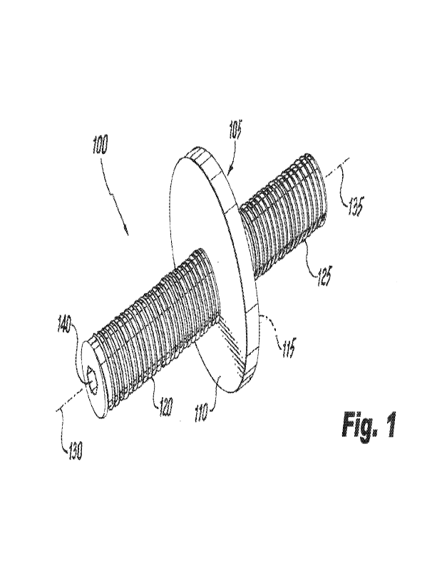
FIG. 1 shows a perspective view of a first attachment device 100 (i.e., an
apparatus) in
accordance with a first illustrative embodiment of the invention. The first
attachment device 100
includes a flange 105 defining an upper surface 110 and a lower surface 115.
An upper shaft 120
projects from the upper surface 110, while a lower shaft 125 projects from the
lower surface 115.
Both the upper shaft 120 and the lower shaft 125 are cylindrical and
externally threaded.
The upper shaft 120 is centered around an upper longitudinal axis 130, while
the lower
shaft 125 is centered about a lower longitudinal axis 135. The upper
longitudinal axis 130 is
laterally offset from the lower longitudinal axis 135. That is, the upper
longitudinal axis 130 is
not collinear with the lower longitudinal axis 135. At the same time, the
upper shaft 120 "vertically
overlaps" the lower shaft 125 in the manner formally defined above. With the
upper shaft 120 and
lower shaft 125 oriented in a vertical direction, at least a portion of the
upper shaft 120 is vertically
directly above at least a portion of the lower shaft 125.
A socket 140 is built into the distal end of the upper shaft 120 opposite the
flange 105. The
socket 140 provides a means of gaining purchase on the first attachment device
100 with a drive
tool in order to rotate the first attachment device 100 during installation.
The socket 140 in the
present illustrative embodiment is hexagonal to accommodate an Allen key
drive, but this shape
is merely by way of illustration and is not intended to be limiting. The
socket 140 may take on a
myriad of shapes to accommodate different drive types. The socket 140 may, for
example, be
replaced by a straight or cruciform slot to allow use of a flat-head or
Phillips-head screwdriver
when installing the first attachment device 100.
3
CA 03184245 2022- 12- 23
WO 2022/005922
PCT/US2021/039286
The socket 140 is centered in the upper shaft 120 of the first attachment
device 100.
However, with the socket 140 centered in the upper shaft 120, the socket 140
is necessarily off-
center with respect to the lower shaft 125. This may cause the drive tool to
wobble when the first
attachment device 100 is rotated while engaging the lower shaft 125 with an
object. To mitigate
this wobble, the socket 140 may instead be placed off-center in the upper
shaft 120 to be better
centered with respect to the lower shaft 125. This assumes, of course, that
the upper shaft 120 and
the lower shaft 125 vertically overlap each other enough to allow this
placement.
In use, the first attachment device 100 may be used to fixate two objects
together with a
lateral offset between the objects that is defined by the first attachment
device 100. That is, with
one object fixated to the upper shaft 120 and the other object fixated to the
lower shaft 125, the
two objects effectively become attached to each other with a lateral offset
equal to the lateral offset
between the upper shaft 120 and the lower shaft 125. The first attachment
device 100 may be
attached to an object in at least three different ways. If the object
comprises an unthreaded through-
hole, the lower shaft 125 may be inserted through the unthreaded through-hole
so that the flange
105 abuts the object. A nut, cap, or the like may then be made to threadably
engage the threads
on the lower shaft 125 and tightened against the object. Alternatively, if the
object provides an
internally-threaded hole having internal threads complementary to the external
threads on the
lower shaft 125, the lower shaft 125 may be made to threadably engage the
internally-threaded
hole to accomplish the fixation. In the latter case, the internally threaded
hole may be a through-
hole (i.e., a hole that passes all the way through the object) or a blind
hole. If the threaded hole is
a through-hole, a nut may be added to the lower shaft 125 to further fixate
the object, creating the
third means of fixation, which is a hybrid of the previous two methods.
Similar methods may be
used to attach another object to the upper shaft 120.
In this manner, the first attachment device 100 is able to attach two objects
together with a
lateral offset equal to the lateral offset between the upper shaft 120 and the
lower shaft 125. A
first object is attached to the upper shaft 120, and a second object is
attached to the lower shaft
125. The upper shaft 120 passes through or into the first object, and the
lower shaft 125 pass es
through or into the second object. The first attachment device 100 can thereby
help to address
misalignments between two objects resulting from error, failure to adhere to
necessary tolerances,
or even mistakes, which are commonplace when constructing complex structures
such as
buildings.
FIGS. 2-4 show an exemplary application wherein the first attachment device
100 is
utilized to fixate a pane of glass 10 to a frame 15. FIG. 2 shows a partially-
exploded perspective
view of the exemplary application, while FIG. 3 shows a fully-exploded
perspective view, and
4
CA 03184245 2022- 12- 23
WO 2022/005922
PCT/US2021/039286
FIG. 4 shows a sectional view along the cleave plane indicated in FIG. 2.
Other elements in the
fixation include an internally-threaded end cap 20, two rubber washers 25, an
insert 30, and an
insert washer 35.
The insert 30 may take on various forms but includes an internally-threaded
hole for
receiving the lower shaft 125 and a means of attachment to the frame 15.
Possible embodiments
of the insert 30 include those described in, for example, International
Publication Number
W02019/164843, which is hereby incorporated by reference herein. In the
present illustrative
embodiment, the insert 30 comprises a baseplate 40 with an externally-threaded
post 50 depending
therefrom. The externally-threaded post 50 tapers to a sharp tip to form a
screw-like shape, which
engages a receiving hole 55 in the frame 15 through the insert washer 35. An
internally-threaded
blind bore 60 extends from the baseplate 40 into the externally-threaded post
50.
To provide the desired fixation, the lower shaft 125 of the first attachment
device 100 is
disposed in and threadably engages the internally-threaded blind bore 60 of
the insert 30. At the
same time, the upper shaft 120 passes through the two rubber washers 25 and
through a through-
hole 65 in the pane of glass 10, where it is threadably engaged by the
internally-threaded end cap
20.
The first attachment device 100 may have any number of dimensions and still
fall within
the scope of the invention. In one illustrative, non-limiting embodiment, for
example, the flange
105 may have a diameter of 2.00 inches and each of the upper shaft 120 and the
lower shaft 125
may have diameters of 0.250 inches. The flange 105 may have a thickness of
0.125 inches. The
lateral offset between the center of the upper shaft 120 and the center of the
lower shaft 125 may
be 0.125 inches, making the offset correspond to one-eighth of an inch.
Nevertheless, in providing
these dimensions, it is again emphasized that these dimensions are merely by
way of example and
not intended to limit the scope of the invention.
It is preferred that, when forming the first attachment device 100, the upper
shaft 120
vertically overlap the lower shaft 125. Such vertical overlap helps to
maintain the strength of the
first attachment device 100 by reducing twisting forces on the flange 105 that
might be present if
the upper shaft 120 were laterally farther displaced from the lower shaft 125.
This preference is
maintained for all embodiments of the invention set forth below.
The first attachment device 100 may be formed of various materials including,
but not
limited to, steel, brass, aluminum, and plastic. Once understood from the
description provided
herein, a person having ordinary skill in the relevant manufacturing arts
would recognize how to
manufacture the first attachment device 100 using conventional manufacturing
techniques and
tooling. The first attachment device 100 may, for example, be milled from a
solid piece of
5
CA 03184245 2022- 12- 23
WO 2022/005922
PCT/US2021/039286
material. Alternatively, the upper shaft 120 and the lower shaft 125 may be
prepared separately
from the flange 105 and then joined thereto using an attachment technique such
as welding.
It should again be emphasized that the above-described embodiments of the
invention are
intended to be illustrative only. Other embodiments can use different types
and arrangements of
elements for implementing the described functionality or adding additional
functionality. These
numerous alternative embodiments will be apparent to one skilled in the art.
For example, FIGS. 5 and 6 show a perspective view and a sectional view,
respectively, of
a second attachment device 200 in accordance with a second illustrative
embodiment of the
invention. The second attachment device 200 includes a flange 205 defining an
upper surface 210
and a lower surface 215. An upper shaft 220 projects upward from the upper
surface 210 and is
centered about an upper longitudinal axis 225, while a lower shaft 230
projects downward from
the lower surface 215 and is centered about a lower longitudinal axis 235. The
upper shaft 220
vertically overlaps the lower shaft 230, but the upper longitudinal axis 225
is not collinear with
the lower longitudinal axis 235.
In the second attachment device 200, both the upper shaft 220 and the lower
shaft 230 are
cylindrical and externally threaded in a manner similar to the first
attachment device 100.
However, unlike the first attachment device 100, neither the upper shaft 220
nor the lower shaft
230 includes a socket or slot. Rather, they are solid throughout (i.e., the
upper shaft 220 and the
lower shaft 230 are devoid of sockets, slots, through-holes, and blind holes).
FIGS. 7 and 8 show a perspective view and a sectional view, respectively, of a
third
attachment device 300 in accordance with a third illustrative embodiment of
the invention. The
third attachment device 300 includes a flange 305 defining an upper surface
310 and a lower
surface 315. An upper shaft 320 projects upward from the upper surface 310 and
is centered about
an upper longitudinal axis 325, while a lower shaft 330 projects downward from
the lower surface
315 and is centered about a lower longitudinal axis 335. The upper shaft 320
vertically overlaps
the lower shaft 330, but the upper longitudinal axis 325 is not collinear with
the lower longitudinal
axis 335.
In the third attachment device 300, both the upper shaft 320 and the lower
shaft 330 are
cylindrical, externally threaded, and have the same diameter. Nevertheless,
unlike the first
attachment device 100 and the second attachment device 200, the third
attachment device 300
includes a through-hole 340, which passes longitudinally through the upper
shaft 320, the flange
305, and the lower shaft 330. The through-hole 340 is linear, internally
threaded, and is centered
in the upper shaft 320 and off-center in the lower shaft 330 because of the
lateral offset between
the upper shaft 320 and the lower shaft 330. The through-hole 340 acts as an
alternative means
6
CA 03184245 2022- 12- 23
WO 2022/005922
PCT/US2021/039286
for attaching objects to the third attachment device 300. A threaded fastener,
for example, may be
made to threadably engage with the through-hole 340 to attach an object to the
third attachment
device 300. In fact, a single threaded fastener may be made to pass all the
way through the upper
shaft 320, the flange 305, and the lower shaft 330 if so desired.
FIGS. 9 and 10 show a perspective view and a sectional view, respectively, of
a fourth
attachment device 400 in accordance with a fourth illustrative embodiment of
the invention. The
fourth attachment device 400 includes a flange 405 defining an upper surface
410 and a lower
surface 415. An upper shaft 420 projects upward from the upper surface 410 and
is centered about
an upper longitudinal axis 425, while a lower shaft 430 projects downward from
the lower surface
415 and is centered about a lower longitudinal axis 435. The upper shaft 420
vertically overlaps
the lower shaft 430, but the upper longitudinal axis 425 is not collinear with
the lower longitudinal
axis 435.
In the fourth attachment device 400, the upper shaft 420 and the lower shaft
430 are both
cylindrical, externally threaded, and have the same diameter. A smooth-bored
through-hole 440
is linear along its entirety and passes longitudinally through the upper shaft
420, the flange 405,
and the lower shaft 125. Again, the smooth-bored through-hole 440 is centered
in the upper shaft
420 and is off-center in the lower shaft 430. The smooth-bored through-hole
440 may act as a
means for passing gases, fluids, or solids through the fourth attachment
device 400. In one or more
applications, for example, a wire or wires (i.e., solids) may be made to pass
through the smooth-
bored through-hole 440.
FIGS. 11 and 12 show a perspective view and a sectional view, respectively, of
a fifth
attachment device 500 in accordance with a fifth illustrative embodiment of
the invention. The
fifth attachment device 500 includes a flange 505 defining an upper surface
510 and a lower surface
515. An upper shaft 520 projects upward from the upper surface 510 and is
centered about an
upper longitudinal axis 525, while a lower shaft 530 projects downward from
the lower surface
515 and is centered about a lower longitudinal axis 535. The upper shaft 520
vertically overlaps
the lower shaft 530, but the upper longitudinal axis 525 is not collinear with
the lower longitudinal
axis 535.
The fifth attachment device 500 is like the fourth attachment device 400 in
that the upper
shaft 520 and the lower shaft 530 are cylindrical, externally threaded, and
have the same diameter,
but, in the fifth attachment device 500, a smooth-bored through-hole 540
passes through the upper
shaft 520, the flange 505, and the lower shaft 530 such that the smooth-bored
through-hole 540 is
centered in both the upper shaft 520 and the lower shaft 530. To accomplish
this, the smooth-
bored through-hole 540 describes an angled path (i.e., a jog) inside the
flange 505. That is, the
7
CA 03184245 2022- 12- 23
WO 2022/005922
PCT/US2021/039286
smooth-bored through-hole 540 describes an angled path in the flange 505 that
is not normal to
the upper surface 510. The smooth-bored through-hole 540 can again be used for
passing gases,
fluids, or solids through the fifth attachment device 500. However, in the
fifth attachment device
500, the smooth-bored through-hole 540 is centered in both the upper shaft 520
and the lower shaft
530, maintaining the strength and integrity of the fifth attachment device
500. The angled path in
the flange 505 allows a smooth transition from the upper longitudinal axis 525
to the lower
longitudinal axis 535. There is, as a result, less chance that wires and such
will get hung up inside
the flange 505.
It will be noted that any gases, fluids, or solids passing through the fifth
attachment device
500 will emerge from the fifth attachment device 500 with a lateral offset
equal to the lateral offset
between the upper longitudinal axis 525 and the lower longitudinal axis 535.
Accordingly, the
fifth attachment device 500 becomes more than a means of attaching objects
with a lateral offset.
The fifth attachment device 500 may also be used to shift the pathways of
gases, fluids, or solids
passing therethrough. There are numerous applications where such a lateral
shift may be desired.
FIGS. 13 and 14 show a perspective view and a sectional view, respectively, of
a sixth
attachment device 600 in accordance with a sixth illustrative embodiment of
the invention. The
sixth attachment device 600 includes a flange 605 defining an upper surface
610 and a lower
surface 615. An upper shaft 620 projects upward from the upper surface 610 and
is centered about
an upper longitudinal axis 625, while a lower shaft 630 projects downward from
the lower surface
615 and is centered about a lower longitudinal axis 635. The upper shaft 620
vertically overlaps
the lower shaft 630, but the upper longitudinal axis 625 is not collinear with
the lower longitudinal
axis 635.
The upper shaft 620 and the lower shaft 630 are cylindrical, externally
threaded, and have
the same diameter in the sixth attachment device 600. A smooth-bored through-
hole 640 passes
through the upper shaft 620, the flange 605, and the lower shaft 630. The
smooth-bored through-
hole 640 is linear along its entirety and makes an angled path through the
upper shaft 620, the
flange 605, and the lower shaft 630 so that the smooth-bored through-hole 640
exits the upper
shaft 620 and the lower shaft 630 in approximately the center of the upper
shaft 620 and the lower
shaft 630, respectively. Stated another way, the smooth-bored through-hole 640
describes an
angled path in the sixth attachment device 600 that is not normal to the upper
surface 610. The
smooth-bored through-hole 640 can again be used for passing gases, fluids, or
solids through the
sixth attachment device 600. The smooth-bored through-hole 640 is
approximately centered in
both the upper shaft 620 and the lower shaft 630, maintaining the strength and
integrity of the sixth
8
CA 03184245 2022- 12- 23
WO 2022/005922
PCT/US2021/039286
attachment device 600. The linear nature of the smooth-bored through-hole 640
even further
reduces the chances that wires and such will get impeded inside the sixth
attachment device 600.
FIGS. 15 and 16 show a perspective view and a sectional view, respectively, of
a seventh
attachment device 700 in accordance with a seventh illustrative embodiment of
the invention. The
seventh attachment device 700 includes a flange 705 defining an upper surface
710 and a lower
surface 715. An upper shaft 720 projects upward from the upper surface 710 and
is centered about
an upper longitudinal axis 725, while a lower shaft 730 projects downward from
the lower surface
715 and is centered about a lower longitudinal axis 735. The upper shaft 720
vertically overlaps
the lower shaft 730, but the upper longitudinal axis 725 is not collinear with
the lower longitudinal
axis 735.
In the seventh attachment device 700, the upper shaft 720 and the lower shaft
730 are both
cylindrical, externally threaded, and have the same diameter. A blind
internally-threaded hole 740
is disposed in the top of the upper shaft 720 opposite the flange 705. The
blind internally-threaded
hole 740 acts as an alternative means of attaching an object to the seventh
attachment device 700
using, for example, a threaded fastener. Advantageously, because the blind
internally-threaded
hole 740 only penetrates partially into the upper shaft 720, there is no
pathway for water to
penetrate through the seventh attachment device 700, as might be the case in,
for example, the
third attachment device 300.
FIGS. 17 and 18 show a perspective view and a sectional view, respectively, of
an eighth
attachment device 800 in accordance with an eighth illustrative embodiment of
the invention. The
eighth attachment device 800 includes a flange 805 defining an upper surface
810 and a lower
surface 815. An upper shaft 820 projects upward from the upper surface 810 and
is centered about
an upper longitudinal axis 825, while a lower shaft 830 projects downward from
the lower surface
815 and is centered about a lower longitudinal axis 835. The upper shaft 820
vertically overlaps
the lower shaft 830, but the upper longitudinal axis 825 is not collinear with
the lower longitudinal
axis 835.
The upper shaft 820 and the lower shaft 830 in the eighth attachment device
800 are
cylindrical and externally threaded. However, in this illustrative embodiment,
the upper shaft 820
and lower shaft 830 have different diameters, demonstrating generally that
upper shafts and lower
shafts in accordance with aspects of the invention need not have the same
diameter. Like the
seventh attachment device 700, the eighth attachment device 800 includes an
upper internally-
threaded blind hole 840 in the top of the upper shaft 820 opposite to the
flange 805. Moreover,
the eighth attachment device 800 includes a lower internally-threaded blind
hole 845 in the bottom
of the lower shaft 830 opposite to the flange 805. Both the upper internally-
threaded blind hole
9
CA 03184245 2022- 12- 23
WO 2022/005922
PCT/US2021/039286
840 and the lower internally-threaded blind hole 845 become alternative means
of attaching objects
to the eighth attachment device 800. Because both the upper internally-
threaded blind hole 840
and the lower internally-threaded blind hole 845 are blind, the chance of
water penetration through
the eighth attachment device 800 is eliminated, as was the case for the
seventh attachment device
700.
FIGS. 19 and 20 show a perspective view and a sectional view, respectively, of
a ninth
attachment device 900 in accordance with a ninth illustrative embodiment of
the invention. The
ninth attachment device 900 includes a flange 905 defining an upper surface
910 and a lower
surface 915. An upper shaft 920 projects upward from the upper surface 910 and
is centered about
an upper longitudinal axis 925, while a lower shaft 930 projects downward from
the lower surface
915 and is centered about a lower longitudinal axis 935. The upper shaft 920
vertically overlaps
the lower shaft 930, but the upper longitudinal axis 925 is not collinear with
the lower longitudinal
axis 935.
The upper shaft 920 and the lower shaft 930 in the ninth attachment device 900
are
cylindrical and have the same diameter. They also include an upper internally-
threaded blind hole
940 and a lower internally-threaded blind hole 945 in the manner of the eighth
attachment device
800. However, the ninth attachment device 900 demonstrates generally that the
upper shaft 920
and the lower shaft 930 need not be externally threaded but may have
unthreaded lateral surfaces
if so desired. Such smooth unthreaded shafts may accommodate the attachment of
hoses to the
ninth attachment device 900 via, for example, conventional hose clamps.
While the flanges in the attachment devices set forth above are circular, they
may take on
different shapes in alternative embodiments. They may, for example, be square,
rectangular,
ovoid, or polygonal. FIG. 21 shows a perspective view of a tenth attachment
device 1000 in
accordance with a tenth illustrative embodiment of the invention. The tenth
attachment device
1000 includes a flange 1005 defining an upper surface 1010 and a lower surface
1015. An upper
shaft 1020 projects upward from the upper surface 1010 and is centered about
an upper
longitudinal axis 1025, while a lower shaft 1030 projects downward from the
lower surface 1015
and is centered about a lower longitudinal axis 1035. The upper shaft 1020
vertically overlaps the
lower shaft 1030, but the upper longitudinal axis 1025 is not collinear with
the lower longitudinal
axis 1035. The flange 1005 is hexagonal, allowing use of a tool such as a
wrench to gain purchase
on the tenth attachment device 1000 during installation.
In addition, auxiliary holes may be added to the flange of one or more of the
above-
described embodiments to obtain a means of attaching the flange itself to an
obj ect by, for example,
threaded fasteners such as bolts or screws. FIG. 22 shows a perspective view
of an eleventh
CA 03184245 2022- 12- 23
WO 2022/005922
PCT/US2021/039286
attachment device 1100 in accordance with an eleventh illustrative embodiment
of the invention.
The eleventh attachment device 1100 is similar to the second attachment device
200. The eleventh
attachment device 1100 includes a flange 1105 defining an upper surface 1110
and a lower surface
1115. An upper shaft 1120 projects upward from the upper surface 1110 and is
centered about an
upper longitudinal axis 1125, while a lower shaft 1130 projects downward from
the lower surface
1115 and is centered about a lower longitudinal axis 1135. The upper shaft
1120 vertically
overlaps the lower shaft 1130, but the upper longitudinal axis 1125 is not
collinear with the lower
longitudinal axis 1135. The flange 1105 defines three auxiliary holes 1140
that pass therethrough.
In the present illustrative embodiment, the three auxiliary holes 1140 are
smooth bored, but in,
alternative embodiments, they may be internally threaded.
As indicated above, attachment devices in accordance with aspects of the
invention allow
one to introduce a lateral offset between an object attached to the upper
shaft and an object attached
to the lower shaft. The desired orientation of this lateral offset between the
objects is usually
determined by the particular application. Nevertheless, when fixating an
attachment device in
accordance with aspects of the invention having externally-threaded upper and
lower shafts (such
as the first attachment device 100) to an object with an internally threaded
hole, the externally
threaded shaft of the attachment device may tighten against the internal
threads of the object at a
point that does not yield the desired lateral-offset orientation. In fact,
without careful engineering
of the shaft and the hole, it is improbable that one would obtain the desired
lateral-offset orientation
by mere chance.
One solution to this issue is to add washers to one or both of the upper shaft
and the lower
shaft to act as standoffs before screwing the upper shaft or the lower shaft
into an object. By use
of the appropriate thickness of these washers, the attachment device will be
tightened against the
object with the lateral offset having the desired orientation. Referring back
to the exemplary
application in FIG. 3, for example, one may set the lateral-offset orientation
of the first attachment
device 100 by placing one or more washers between the first attachment device
100 and the insert
30. Nevertheless, addition of washers in this manner may require some trial
and error.
Accordingly, another means of providing the desired standoff distance is
desirable where the
orientation of the lateral offset is critical.
FIGS. 23 and 24 show aspects of a twelfth attachment device 1200 in accordance
with a
twelfth illustrative embodiment of the invention that includes an optional
adjustable standoff
assembly that can be easily adjusted to create the desired standoff between
the twelfth attachment
device 1200 and an object being fixated. FIG. 23 shows a perspective view of
the twelfth
11
CA 03184245 2022- 12- 23
WO 2022/005922
PCT/US2021/039286
attachment device 1200, while FIG. 24 shows a sectional view along the cleave
plane indicated in
FIG. 21.
The twelfth attachment device 1200 includes a flange 1205 from which projects
an upper
shaft 1210 and a lower shaft 1215 in the manner of the first attachment device
100. However, the
flange 1205 in the twelfth attachment device 1200 includes three threaded
holes 1220 in which set
screws 1225 are engaged. A washer 1230 encircles the lower shaft 1215 and is
disposed below
the flange 1205.
While in use, the set screws 1225 protrude below the flange 1205 towards the
washer 1230
and act to determine the distance d between the flange 1205 and the washer
1230. That is, the
distanced between the flange 1205 and the washer 1230 is determined by an
extent by which the
set screws 1225 protrude from the flange 1205 towards the washer 1230. If the
distance 1235 is
not that desired, the set screws 1225 may be rotated one way or the other to
create greater or lesser
distance d between the flange 1205 and the washer 1230. Ultimately, the
distance 1235 can be
tailored so that an object threadably engaged with the lower shaft 1215
tightens to the lower shaft
1215 at precisely the point where the orientation of the lateral offset falls
as desired. The twelfth
attachment device 1200 thereby provides an easy-to-use solution for placing
the lateral offset into
the desired orientation.
The characteristics of the many embodiments set forth above may be mixed and
matched
to form other embodiments falling within the scope of the invention. For
example, an attachment
device falling within the scope of the invention may contain an upper shaft
that is externally
threaded in the manner of the first attachment device 100 in combination with
a lower shaft that
defines an unthreaded lateral surface in the manner of the ninth attachment
device 900. Another
attachment device falling within the scope of the invention may have upper and
lower shafts that
are cylindrical, externally threaded, and solid (i.e., devoid of sockets,
slots, through-holes, and
blind holes) in the manner of the second attachment device 200 but have an
upper shaft that differs
in diameter from its lower shaft in the manner of the eighth attachment device
800. Even another
attachment device in accordance with aspects of the invention may have an
upper shaft with a
socket in the manner of the first attachment device 100, and a lower shaft
with a blind internally-
threaded hole in the manner of the eighth attachment device 800. These many
possible iterations
and others will be apparent to one skilled in the art.
All the features disclosed herein may be replaced by alternative features
serving the same,
equivalent, or similar purposes, unless expressly stated otherwise. Thus,
unless expressly stated
otherwise, each feature disclosed is one example only of a generic series of
equivalent or similar
features.
12
CA 03184245 2022- 12- 23