Note: Descriptions are shown in the official language in which they were submitted.
CA 03184885 2022-11-24
WO 2021/247395 PCT/US2021/034769
SOFT TISSUE IMPLANT SYSTEMS, INSTRUMENTS, AND RELATED METHODS
CROSS REFERENCE TO RELATED APPLICATION
[0001] This application claims benefit of priority of U.S. Provisional
Patent Application
No. 63/034,066, filed June 3, 2020, and entitled "Soft Tissue Implant systems,
Instruments,
and Related Methods," the disclosure of which is hereby incorporated herein by
reference in
its entirety.
FIELD
[0002] The present disclosure relates to soft tissue implant systems,
instruments, and
related methods. The present disclosure relates to podiatric and orthopedic
implants and
surgery related to repairs of soft tissue and/or bone. More specifically, but
not exclusively,
the present disclosure relates to instruments, implants, systems, assemblies,
and methods for
joining soft tissue to soft tissue, soft tissue to bone, and bone to bone.
BACKGROUND
[0003] The plantar plate is a thick ligamentous (fibrocartilaginous)
structure on the
bottom of the foot under a metatarsophalangeal joint (MTP joint). A plantar
plate attaches to
a metatarsal bone and a corresponding proximal phalanx bone. A plantar plate
provides
stability to the MTP joint by withstanding compressive loads from the
metatarsal head and
tensile loads in line with the toe axis. A plantar plate also cushions the
bottom of an MTP
joint and the distal head of a metatarsal while standing, walking, running,
and the like. A
plantar plate also helps bring the corresponding toe toward the floor while
standing.
[0004] A plantar plate may become torn or otherwise compromised, such as
due to
biomechanical abnormalities and/or imbalances in the foot that cause overload
of one of the
metatarsals and/or MTP joints. Examples of biomechanical abnormalities and/or
imbalances
include a long first metatarsal, a short second metatarsal, a short third
metatarsal, an untreated
metatarsus adductus deformity (e.g., a pigeon toe deformity), arthritis of the
great toe (first
metatarsal, first proximal phalanx and/or first distal phalanx), and prior
cortisone injection
into a plantar plate.
[0005] The tissue of the plantar plate itself may become attenuated, tear
or otherwise
become segmented along its length between corresponding metatarsal and
proximal phalanx
bones. Alternatively, a plantar plate may tear from or otherwise become
decoupled from
1
CA 03184885 2022-11-24
WO 2021/247395 PCT/US2021/034769
corresponding metatarsal or proximal phalanx bones. A torn plantar plate
typically causes
persistent ball of the foot pain and/or changes in the position/alignment of
the affected toe
and/or adjacent toe(s) (e.g., hammertoe). Both acute and, more commonly,
chronic injuries to
the plantar plate can cause a range of injury types, such as instability
(particularly in the 2nd
and 3rd MTP joints, medial deviation of the toe, "crossover toe", pain and
discomfort, for
example).
[0006] Other tissues and/or bones of the foot, and other parts of a
mammalian (e.g.,
human) body, similarly may become torn or otherwise be segmented or separated
such that
joining of the portions of the tissues and/or bones may be anatomically and/or
physiologically
advantageous or desirable. For example, the human hand includes a palmar
plate. The
palmar plate is an analogous structure to the plantar plate. A palmar plate is
associated with
each metacarpophalangeal joint (MCP joint) and each interphalangeal joint in
the hand. Like
the plantar plate, the palmar plate may tear.
[0007] Typical plantar plate repair options include suturing/re-
approximating the tear in
the plantar plate tissue to induce healing, or re-attaching the tissue to the
insertion point at the
base of the proximal phalanx. Current systems for plantar plate repair (and
repairs of other
tissues and/or bones of the foot, and other parts of the human body) tend to
be bulky and/or
complex. Current systems also typically require multiple and/or relatively
large through holes
to be formed per tissue and/or bone connection in order to join/repair the
portions, which can
weaken the construct.
[0008] All-suture soft anchor implants generally rely on bone quality and
consistency for
deployment. When tension is applied to anchors of an implant, those anchors
deform within
the cancellous bone space and deploy against the cortical bone to provide
secure anchoring.
In cases where bone quality or consistency is not optimal, these anchors may
fail to deploy.
Products can have up to about a ten percent non-deployment rate.
[0009] Thus, there is a need for instruments, implants, systems,
assemblies, and methods
for plantar plate repair, and joining of other tissues and/or bones of the
foot and other parts of
a mammalian (e.g., human) body, that are compact, maneuverable and simple to
use. There
is also need for tissue and/or bone repair/joining instruments for deployment
of implants,
systems, assemblies, and methods that do not require a plurality of and/or
relatively large
through holes formed in each of the joined tissue and/or bone segments.
[0010] The present disclosure is directed to overcoming these and other
deficiencies in
the art.
2
CA 03184885 2022-11-24
WO 2021/247395 PCT/US2021/034769
SUMMARY
[0011] A first aspect relates to an instrument. The instrument includes a
handle portion;
an inserter portion comprising an insertion portion and a tip portion; a guide
portion
comprising a medial end component and a distal end component, the guide
portion extending
from a distal end portion of the handle portion to a bone engagement end of
the inserter
portion; a passageway extending through the inserter portion from the distal
end of the handle
portion to the bone engagement end of the inserter portion; and a hole that
extends from the
exterior surface of the handle portion and the guide portion to the
passageway, wherein the
guide portion is configured such that the insertion portion and the tip
portion of the inserter
portion are positioned past the distal end component of the guide portion when
the handle
portion, the inserter portion, and the guide portion are mated.
[0012] In one embodiment, the guide portion further comprises a guide
handle. In
another embodiment, the handle portion comprises a first coupling portion. In
another
embodiment, the handle portion comprises a second coupling portion. In one
embodiment,
the instrument further includes an end cap portion.
[0013] In one embodiment, the instrument further includes a cavity
extending from a
proximal end of the handle portion to the distal end of the handle portion. In
another
embodiment, the distal end of the second coupling portion of the handle
portion comprises an
opening. In one embodiment, the tip portion comprises at least one tooth. In
one
embodiment, the tip portion comprises a forked free end. In another
embodiment, the tip
portion comprises a pair of tines and a base portion extending therebetween.
In another
embodiment, the tip portion comprises a pair of grooves extending proximally
from the base
portion of a forked free end. In one embodiment, the tip portion is configured
to retain an
anchor tube of an implant thereon.
[0014] In one embodiment, the instrument further includes an implant
system, wherein a
first flexible anchor tube or a second flexible anchor tube of the implant
system is retained on
the tip portion. In another embodiment, one or more end portions of a first
flexible anchor
tube or a second flexible anchor tube retained on the tip portion extends
within the pair of
grooves of the tip portion, and a medial portion thereof extends over a base
portion between a
pair of tines.
[0015] A second aspect relates to a bone and/or tissue joining implant
system. The
system includes an instrument comprising a handle portion; an inserter portion
comprising an
insertion portion and a tip portion; a guide portion comprising a medial end
component and a
distal end component, the guide portion extending from a distal end portion of
the handle
3
CA 03184885 2022-11-24
WO 2021/247395 PCT/US2021/034769
portion to a bone engagement end of the inserter portion; a passageway
extending through the
inserter portion from the distal end of the handle portion to the bone
engagement end of the
inserter portion; and a hole that extends from the exterior surface of the
handle portion and
the guide portion to the passageway, wherein the guide portion is configured
such that the
insertion portion and the tip portion of the inserter portion are positioned
past the distal end
component of the guide portion when the handle portion, the inserter portion,
and the guide
portion are mated, and one or more sutures.
[0016] In one embodiment, the guide portion further comprises a guide
handle. In
another embodiment, the handle portion comprises a first coupling portion. In
another
embodiment, the handle portion comprises a second coupling portion. In one
embodiment,
the bone and/or tissue joining implant system further includes an end cap
portion.
[0017] In one embodiment, the bone and/or tissue joining implant system
further includes
a cavity extending from a proximal end of the handle portion to the distal end
of the handle
portion. In another embodiment, the distal end of the second coupling portion
of the handle
portion comprises an opening. In one embodiment, the tip portion comprises at
least one
tooth. In another embodiment, the tip portion comprises a forked free end. In
one
embodiment, the tip portion comprises a pair of tines and a base portion
extending
therebetween. In another embodiment, the tip portion comprises a pair of
grooves extending
proximally from the base portion of a forked free end. In yet another
embodiment, the tip
portion is configured to retain an anchor tube of an implant thereon.
[0018] In one embodiment, the bone and/or tissue joining implant system
further includes
a first flexible anchor tube or a second flexible anchor tube of the implant
system that is
retained on the tip portion. In another embodiment, one or more end portions
of a first
flexible anchor tube or a second flexible anchor tube retained on the tip
portion extends
within the pair of grooves of the tip portion, and a medial portion thereof
extends over a base
portion between a pair of tines.
[0019] A third aspect relates to a method of using an instrument to deploy
a bone and/or
tissue joining implant system. The method includes providing an instrument,
the instrument
comprising a handle portion; an inserter portion comprising an insertion
portion and a tip
portion; a guide portion comprising a medial end component and a distal end
component, the
guide portion extending from a distal end portion of the handle portion to a
bone engagement
end of the inserter portion; a passageway extending through the inserter
portion from the
distal end of the handle portion to the bone engagement end of the inserter
portion; and a hole
that extends from the exterior surface of the handle portion and the guide
portion to the
4
CA 03184885 2022-11-24
WO 2021/247395 PCT/US2021/034769
passageway, wherein the guide portion is configured such that the insertion
portion and the
tip portion of the inserter portion are positioned past the distal end
component of the guide
portion when the handle portion, the inserter portion, and the guide portion
are mated. The
method further includes passing a first anchor tube through at least a portion
of a first bone or
tissue segment; passing a first end portion of at least one suture through a
first portion of a
second bone or tissue segment; and passing a second end portion of at least
one suture
through a second portion of a second bone or tissue segment.
[0020] In one embodiment, the method further includes tensioning the first
and second
end portions of the at least one suture in divergent directions to seat the
first anchor tube
against the first bone or tissue segment, deform the first anchor tube, and
drawing the first
bone or tissue segment and the second bone or tissue segment together. In a
further
embodiment, the method further includes tying the first and second end
portions of the at
least one suture in a knot to fix the relationship of the first bone or tissue
segment and the
second bone or tissue segment. In yet another embodiment, passing the first
anchor tube
through at least a portion of the first bone or tissue segment comprises
passing the first
anchor tube partially through a first bone segment past a cortex thereof
[0021] In one embodiment, passing the first end portion of the at least one
suture through
the first portion of the second bone or tissue segment comprises passing an
instrument
coupled to the first end portion of the at least one suture through the first
portion of the
second bone or tissue segment; and passing the second end portion of the at
least one suture
through the second portion of the second bone or tissue segment comprises
passing an
instrument coupled to the second end portion of the at least one suture
through the second
portion of the second bone or tissue segment.
[0022] In one embodiment, passing the first end portion of the at least one
suture through
the first portion of the second bone or tissue segment comprises first passing
the first end
portion of the at least one suture through the first portion of the second
bone or tissue
segment from a first surface of the second bone or tissue segment that is
adjacent to the first
bone or tissue segment to a second surface of the second bone or tissue
segment that is distal
to the first bone or tissue segment, and passing the second end portion of the
at least one
suture through the second portion of the second bone or tissue segment
comprises first
passing the second end portion of the at least one suture through the second
portion of the
CA 03184885 2022-11-24
WO 2021/247395 PCT/US2021/034769
second bone or tissue segment from the first surface to the second surface of
the second bone
or tissue segment.
[0023] In one embodiment, the first bone or tissue segment comprises a
proximal phalanx
and the second bone or tissue segment comprises a plantar plate. In another
embodiment, the
guide portion further comprises a guide handle. In another embodiment, the
handle portion
comprises a first coupling portion. In yet another embodiment, the handle
portion comprises
a second coupling portion. In one embodiment, the method further includes an
end cap
portion. In another embodiment, the method further includes a cavity extending
from a
proximal end of the handle portion to the distal end of the handle portion. In
one
embodiment, the distal end of the second coupling portion of the handle
portion comprises an
opening.
[0024] In one embodiment, the tip portion comprises at least one tooth. In
another
embodiment, the tip portion comprises a forked free end. In another
embodiment, the tip
portion comprises a pair of tines and a base portion extending therebetween.
In yet another
embodiment, the tip portion comprises a pair of grooves extending proximally
from the base
portion of a forked free end. In one embodiment, the tip portion is configured
to retain an
anchor tube of an implant thereon. In one embodiment, the method further
includes an
implant system, wherein a first flexible anchor tube or a second flexible
anchor tube of the
implant system is retained on the tip portion. In one embodiment, the one or
more end
portions of a first flexible anchor tube or a second flexible anchor tube
retained on the tip
portion extends within the pair of grooves of the tip portion.
[0025] The present disclosure is directed toward devices and methods for
joining tissue
and/or bone segments or portions. The instruments, implants, systems,
assemblies, and
methods for joining soft tissue to soft tissue, soft tissue to bone, and bone
to bone may be
used for repairing a torn plantar plate. However, the instruments, implants,
systems,
assemblies, and methods may be equally employed to repair/join any other
tissue and/or bone
segments or portions of the foot or other parts of the mammalian (e.g., human)
body.
[0026] The present disclosure relates to deploying soft anchors using
accessory
instrumentation or features that do not rely solely on native bone for use. In
particular, the
present disclosure relates to a feature for an inserter to aid in deployment
of an implant. The
feature may, for example, be a thin-walled sleeve that is designed to be
inserted into a
prepared bone hole behind an anchor and kept in place while an insertion fork
is removed. In
this way, the anchor deploys against the sleeve rather than relying on the
cortical wall for
anchor deployment. The present disclosure allows for the operator to have
tactile
6
CA 03184885 2022-11-24
WO 2021/247395 PCT/US2021/034769
confirmation of anchor deployment and does not depend solely on native bone
quality and
consistency for deployment.
[0027] These and other objects, features, and advantages of the aspects
disclosed herein
will become apparent from the following detailed description of the various
aspects of the
invention taken in conjunction with the accompanying drawings.
BRIEF DESCRIPTION OF THE DRAWINGS
[0028] The accompanying drawings, which are incorporated in and constitute
a part of
the specification, illustrate embodiments of the inventions and together with
the detailed
description herein, serve to explain the principles of the inventions. It is
emphasized that, in
accordance with the standard practice in the industry, various features may or
may not be
drawn to scale. In fact, the dimensions of the various features may be
arbitrarily increased or
reduced for clarity of discussion. The drawings are only for purposes of
illustrating
embodiments of inventions of the disclosure and are not to be construed as
limiting the
inventions.
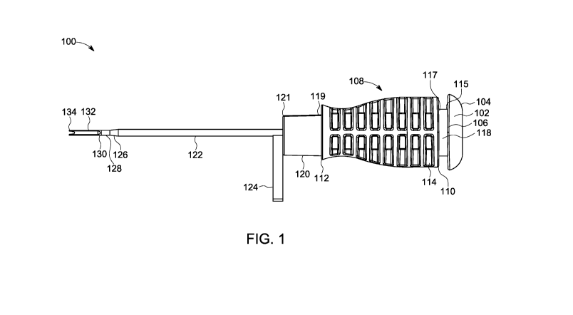
[0029] FIG. 1 is a side view of an exemplary drill guide and inserter
system for
facilitating implantation of an implant system, in accordance with the present
disclosure;
[0030] FIG. 2 is a side view of an exemplary drill guide and inserter
system for
facilitating implantation of an implant system, in accordance with the present
disclosure;
[0031] FIG. 3 is a top perspective view of an exemplary drill guide and
inserter system
for facilitating implantation of an implant system, in accordance with the
present disclosure;
[0032] FIG. 4 is a bottom perspective view of an exemplary drill guide and
inserter
system for facilitating implantation of an implant system, in accordance with
the present
disclosure;
[0033] FIG. 5 is a front view of an exemplary drill guide and inserter
system for
facilitating implantation of an implant system, in accordance with the present
disclosure;
[0034] FIG. 6 is a rear view of an exemplary drill guide and inserter
system for
facilitating implantation of an implant system, in accordance with the present
disclosure;
[0035] FIG. 7 is a back elevational, perspective view of an exemplary drill
guide and
inserter system for facilitating implantation of an implant system, in
accordance with the
present disclosure;
[0036] FIG. 8 is a back elevational, perspective view of an exemplary drill
guide and
inserter system for facilitating implantation of an implant system, in
accordance with the
present disclosure;
7
CA 03184885 2022-11-24
WO 2021/247395 PCT/US2021/034769
[0037] FIG. 9 is an exploded side view of an exemplary drill guide and
inserter system
for facilitating implantation of an implant system, in accordance with the
present disclosure;
[0038] FIG. 10 is an exploded side view of an exemplary drill guide and
inserter system
for facilitating implantation of an implant system, in accordance with the
present disclosure;
[0039] FIG. 11 is an exploded top view of an exemplary drill guide and
inserter system
for facilitating implantation of an implant system, in accordance with the
present disclosure;
[0040] FIG. 12 is an exploded bottom view of an exemplary drill guide and
inserter
system for facilitating implantation of an implant system, in accordance with
the present
disclosure;
[0041] FIG. 13 is a front elevational, perspective view of an exemplary
drill guide and
inserter system for facilitating implantation of an implant system, in
accordance with the
present disclosure;
[0042] FIG. 14 is a front elevational, perspective view of an exemplary
drill guide and
inserter system for facilitating implantation of an implant system, in
accordance with the
present disclosure;
[0043] FIG. 15 is a perspective view of an implant retaining tip of the
inserter of the drill
guide and inserter system for facilitating implantation of an implant system
of FIG. 1, in
accordance with the present disclosure;
[0044] FIG. 16 illustrates an exemplary method of inserting an anchor
through a bone
hole via the drill guide and inserter system for facilitating implantation of
an implant system,
in accordance with the present disclosure; and
[0045] FIG. 17 illustrates an anchor deployment upon retraction of the
insertion fork via
the drill guide and inserter system for facilitating implantation of an
implant system, in
accordance with the present disclosure.
DETAILED DESCRIPTION
[0046] In this detailed description and the following claims, the words
proximal, distal,
anterior or plantar, posterior or dorsal, medial, lateral, superior and
inferior are defined by
their standard usage for indicating a particular part or portion of a bone or
implant according
to the relative disposition of the natural bone or directional terms of
reference. For example,
"proximal" means the portion of a device or implant nearest the torso, while
"distal" indicates
the portion of the device or implant farthest from the torso. As for
directional terms,
"anterior" is a direction towards the front side of the body, "posterior"
means a direction
8
CA 03184885 2022-11-24
WO 2021/247395 PCT/US2021/034769
towards the back side of the body, "medial" means towards the midline of the
body, "lateral"
is a direction towards the sides or away from the midline of the body,
"superior" means a
direction above and "inferior" means a direction below another object or
structure. Further,
specifically in regards to the foot, the term "dorsal" refers to the top of
the foot and the term
"plantar" refers the bottom of the foot.
[0047] Similarly, positions or directions may be used herein with reference
to anatomical
structures or surfaces. For example, as the current implants, devices,
instrumentation, and
methods are described herein with reference to use with the bones of the foot,
the bones of
the foot, ankle and lower leg may be used to describe the surfaces, positions,
directions or
orientations of the implants, devices, instrumentation and methods. Further,
the implants,
devices, instrumentation, and methods, and the aspects, components, features
and the like
thereof, disclosed herein are described with respect to one side of the body
for brevity
purposes. However, as the human body is relatively symmetrical or mirrored
about a line of
symmetry (midline), it is hereby expressly contemplated that the implants,
devices,
instrumentation, and methods, and the aspects, components, features and the
like thereof,
described and/or illustrated herein may be changed, varied, modified,
reconfigured or
otherwise altered for use or association with another side of the body for a
same or similar
purpose without departing from the spirit and scope of the invention. For
example, the
implants, devices, instrumentation, and methods, and the aspects, components,
features and
the like thereof, described herein with respect to the right foot may be
mirrored so that they
likewise function with the left foot. Further, the implants, devices,
instrumentation, and
methods, and the aspects, components, features and the like thereof, disclosed
herein are
described with respect to the foot for brevity purposes, but it should be
understood that the
implants, devices, instrumentation, and methods may be used with other bones
of the body
having similar structures.
[0048] Generally stated, disclosed herein are instruments, implants,
systems, assemblies,
and methods for joining soft tissue to soft tissue, soft tissue to bone, and
bone to bone. The
implants, systems, assemblies and methods may be used for repairing a torn
plantar plate of a
metatarsophalangeal joint (MTP joint). While the instruments, implants,
systems,
assemblies, and methods may be illustrated and described in the present
disclosure in the
context of plantar plate repair, the instruments, implants, systems,
assemblies, and methods
may equally be employed or may be adapted without undue experimentation to
join any soft
tissue to any soft tissue, any soft tissue to any bone, or any bone to any
bone. For example,
the instruments, implants, systems, assemblies, and methods may be equally
employed to
9
CA 03184885 2022-11-24
WO 2021/247395 PCT/US2021/034769
repair/join any other tissue and/or bone segments or portions of the foot or
other parts of the
mammalian (e.g., human) body, such as but not limited to a torn palmar plate.
[0049] The instruments, implants, systems, assemblies, and related methods
for joining
soft tissue to soft tissue, soft tissue to bone, and bone to bone of the
present disclosure may be
similar to, such as include at least one feature or aspect of, the implants,
systems, assemblies
and related methods disclosed in U.S. Provisional Patent Application No.
62/968,765, filed
on January 31, 2020, and entitled Knotless Soft Tissue Implant Systems and
Related
Methods; U.S. Provisional Patent Application No. 62/775,591, filed on December
5, 2018,
and entitled Implant System and Methods of Use; U.S. Provisional Patent
Application No.
62/883,429, filed on August 6, 2019, and entitled Soft Tissue Implant Systems,
Instruments
and Related Method; and/or International PCT Application No.
PCT/U52019/064741, filed
on December 5, 2019, and entitled Soft Tissue Implant Systems, Instruments and
Related
Methods, which are hereby incorporated herein by reference in their
entireties. Similarly, the
instruments, implants, systems, assemblies, and related methods for joining
soft tissue to soft
tissue, soft tissue to bone, and bone to bone of the present disclosure may
include one or
more instrument (e.g., one or more insertion and/or implantation instruments)
disclosed in
U.S. Provisional Patent Application No. 62/968,765, filed on January 31, 2020,
and entitled
Knotless Soft Tissue Implant Systems and Related Methods; U.S. Provisional
Patent
Application No. 62/883,429, filed on August 6, 2019, and entitled Soft Tissue
Implant
Systems, Instruments and Related Method; and/or International PCT Application
No.
PCT/U52019/064741, filed on December 5, 2019, and entitled Soft Tissue Implant
Systems,
Instruments and Related Methods, which are incorporated herein by reference in
their
entireties.
[0050] Referring to the drawings, wherein like reference numerals are used
to indicate
like or analogous components throughout the several views, and with particular
reference to
FIGS. 1-17, there is illustrated an exemplary embodiment of a drill guide and
inserter system
100 for joining soft tissue to soft tissue, soft tissue to bone, or bone to
bone according to the
present disclosure.
[0051] FIGS. 1-17 illustrate an exemplary drill guide and inserter system,
instrument,
device or apparatus 100 for facilitating implantation of an implant system in
accordance with
the present disclosure. The drill guide and inserter system 100 is configured
to create one or
more through holes in one or more bones or tissues and to implant an implant
system
into/through the one or more through holes in the one or more bones or
tissues.
CA 03184885 2022-11-24
WO 2021/247395 PCT/US2021/034769
[0052] As shown in FIGS. 1-4 and 9-14, the drill guide and inserter system
100 includes
a handle portion or component 108, an inserter portion or component 138 (see,
e.g., FIGS. 9-
13), and a guide portion or component 122 that are configured to nest or
otherwise couple
together. As shown in FIGS. 1-4, the handle portion 108 is manually engageable
and
includes a first coupling portion 118 of the handle portion 108 and a second
coupling portion
120 of the handle portion 108. The handle portion 108 may further be proximate
to inserter
portion 138 or a component that extends from or past a distal end 112 of the
handle portion
108 (e.g., the second coupling portion) and defines a bone engagement free end
130.
[0053] As shown in FIGS. 1-4, the handle portion 108 of the drill guide and
inserter
system 100 comprises both a proximal end 110 of the handle portion 108 and a
distal end 112
of the handle portion 108. The handle portion 108 is configured to allow a
user to securely
grasp the handle portion 108 using one hand and position the guide portion 122
and bone
engagement free end 130 of the insertion portion 132 and/or inserter portion
138 against a
bone (e.g., a plantar side of a proximal phalanx). In one embodiment, the
handle portion may
include a distal projection to further allow for a user to securely grasp the
handle portion 108
using one hand and position the guide portion 122 and the free end of the
insertion portion
132 and/or inserter portion 138 against a bone (e.g., a plantar side of a
proximal phalanx).
The handle portion 108 is also configured to allow the user to secure the
guide portion 122
and tip portion 134 of the inserter portion 138 against a bone via one hand
(e.g., a plantar side
of a proximal phalanx) by applying pressure to the drill guide and inserter
system 100 via the
user's thumb against the proximal side of the handle, and potentially wrapping
one or more
fingers of the user's hand around the opposing side of the bone (e.g., the
dorsal aspect of the
patient's foot) to provide back pressure.
[0054] As further shown in FIGS. 1, 2, 9, and 10, for example, the tip
portion 134 of the
insertion portion 132 of inserter portion 138 may provide at least one
relatively sharp point,
tip or tooth that may securely engage bone to provide stability of the
placement of the drill
guide and inserter system 100 and the inserter portion 138 against the bone
while the guide
portion 122 surrounds the inserter portion 138, while in use. For example, in
one
embodiment, the tip portion 134 of the insertion portion 132 comprises a
plurality of
angularly or circumferentially spaced teeth configured to engage bone, as
shown in FIGS. 1,
2, 9 and 10.
[0055] The handle portion 108 may include on the proximal end 110 of the
handle
portion 108 a first coupling portion 118. The first coupling portion 118 may
include a distal
end 117 which may be adjacent to the proximal end of 112 of the handle and may
further
11
CA 03184885 2022-11-24
WO 2021/247395 PCT/US2021/034769
include a proximal end 115 which may be adjacent to an end cap portion 102.
The handle
portion 108 may further include on the distal end 112 of the handle portion
108 a second
coupling portion 120. The second coupling portion 120 may include a distal end
121 which
may be adjacent to the inserter portion 138 and may further include a proximal
end 119
which may be adjacent to the distal end 110 of the handle portion 108.
[0056] The handle portion 108 may include an inserter aperture or cavity
116 (see FIG. 4)
extending from the proximal end 110 of the handle portion 108 to the distal
end 112 the
handle portion 108 and toward the inserter portion 138 and the guide portion
122 and may be
configured to accept therein or mate with a first coupling portion 118 at the
proximal end 110
of the handle portion 108 and a second coupling portion 120 at the distal end
112 of the
handle portion 108 as shown in FIGS. 4 and 14, for example. The cavity 116 may
be open or
exposed at the distal end 112 of the handle portion 108 and may be open or
exposed at the
proximal end 110 of the handle portion 108. The cavity 116 may further be open
or exposed
at the distal end 121 of the second coupling portion 120 of handle portion 108
and may be
open or exposed at the proximal end 119 of the second coupling portion, 120 of
handle
portion 108 thereby forming a slot or opening 136 (see FIGS. 13 and 14) at the
distal end 121
of the second coupling portion 120.
[0057] As shown in FIGS. 5 and 13-15, the inserter portion 138 and the
handle portion
108 are cannulated, hollow or otherwise include cooperating through holes that
form an
internal passageway or through hole 140 that may extend through the inserter
portion 138
from the tip portion 134 of the inserter portion 138 and the tip portion of
the insertion portion
132 to the proximal end 110 of the handle portion 108. The internal passageway
140 may
also be open or exposed at the tip portion 134 of the inserter portion 138 and
the tip portion
of the insertion portion 132 and is also open or exposed at the proximal end
110 of the handle
portion 108. The internal passageway 142 through the handle portion 108 may
extend for the
length of the handle portion 108 and may extend for the length of the first
coupling portion
118 of the handle portion 108 and the second coupling portion 120 of the
handle portion 108.
The inserter portion 138 may be surrounded by guide portion 122 to aid in
deployment of an
anchor during implant surgery.
[0058] The internal passageway 140 is configured to accept a corresponding
drilling
member (such as a k-wire, drill bit, or other elongate drilling mechanism)
therethrough. With
the tip portion 134 of the insertion portion 132 engaged with a bone, the
inserter portion 138
may be introduced into the internal passageway 140 at the proximal end 110 of
the handle
portion 108, and advanced through internal passageway 140 of the handle
portion 108 and the
12
CA 03184885 2022-11-24
WO 2021/247395 PCT/US2021/034769
inserter portion 138 to the bone, all while the inserter portion 138 is
proximate to a guide
portion 122. The drilling member can then be rotated or otherwise utilized to
create a hole or
aperture into, and potentially through, the bone. At least a portion of the
internal passageway
140 of the inserter portion 138 may approximate the cross-sectional size
(e.g., diameter) of
the drilling member to guide the drilling member and prevent the drilling
member from
wandering and/or angling during a drilling operation.
[0059] The inserter portion 138, the handle portion 108, and the guide
portion 122 may
include one or more holes, slots, or openings that extend through the exterior
surfaces thereof
to the internal passageway 140. The inserter portion 138, the handle portion
108, and the
guide portion 122 may also include holes that extend from the tip portion 134
of the insertion
portion 132 of inserter portion 138 to the proximal end 110 of the handle
portion 108. The
one or more holes may be in communication with the exterior of the drill guide
and inserter
system 100 (e.g., the exterior of the handle portion 108 and/or the exterior
of the guide
portion 122) and the internal passageway 140 and the internal passageway 142
to provide
access to and from the internal passageway 140 and the internal passageway
142. The width
of the hole is less than the cross-sectional size of the drilling member to
prevent the drilling
member from disengaging from the internal passageway 140 and the internal
passageway 142
during a drilling operation. In one embodiment, the width of the hole may be
greater than a
cross-sectional size of the strands of a tensioning suture and the strands of
a shuttle suture of
an implant coupled or loaded onto the inserter portion 138.
[0060] As shown in FIGS. 1-4 and 7-12, one end of the inserter portion 138
is attached to
the manually engageable handle portion 108 and the opposing end of the
inserter portion 138
is attached to an insertion portion 132 that extends from or past a distal end
112 of the handle
portion 108 and defines an implant holder free end or tip portion 134. The
insertion portion
132, tip portion 134, and bone engagement free end of inserter 130 may extend
beyond the
guide portion 122. As noted above, the distal end 112 of the handle portion
108 may include
a second coupling portion 120. The second coupling portion 120 has a distal
end 121 that is
adjacent to the inserter portion 138 and also has a proximal end 119 that is
adjacent to the
distal end 112 of the handle portion 108. The second coupling portion 120 is
configured to
extend into and securely mate with the cavity 116 extending from the proximal
end 110 of the
handle portion 108 to the distal end 112 of the handle portion 108 of the
drill guide and the
inserter system 100. The handle portion 108 may also include a stop surface
proximate to the
second coupling portion 120 of the handle portion 108 that is configured to
abut against the
distal end 110 of the handle portion 108 of the drill guide and inserter
system 100 when the
13
CA 03184885 2022-11-24
WO 2021/247395 PCT/US2021/034769
second coupling portion 120 of handle portion 108 is fully seated within the
cavity 116. The
handle portion 108 may also include a stop surface proximate to the first
coupling portion
118 of the handle portion 108 that is configured to abut against the proximate
end 110 of the
handle portion 108 of the drill guide and inserter system 100 when the first
coupling portion
118 of the handle portion 108 is fully seated within the cavity 116.
[0061] The handle portion 108 of the drill guide and inserter system 100
may include the
internal cavity or passageway 142 that is in communication with the passageway
140 of the
inserter portion 138 when the inserter portion 138 is fully mated with the
handle portion 108.
The handle portion 108 may include one or more of a slot, hole, or opening 114
that extends
from the exterior surface the handle portion 108 to the internal passageway
142. The inserter
portion 138 may include an internal passageway 140 which may extend from the
tip portion
134 of the insertion portion 132 of the inserter portion 138 to the proximal
end 110 of the
handle portion 108, or may extend from the tip portion 134 of the insertion
portion 132 of the
inserter portion 138 to the proximal end 119 of the second coupling portion
120 of the handle
portion 108. The internal passageway 140 may be in communication with the
exterior of the
handle portion 108 and the internal passageway 140. The slot 114 may also
provide access to
and from the internal passageway 140.
[0062] The proximal end 110 of the handle portion 108 may define an end
surface that
can be utilized to apply pressure to the inserter portion 138. In some
embodiments, the
proximal end 110 of the handle portion 108 may be defined by a removable end
cap portion
102 that closes off and/or mates within the internal passageway 142 of the
handle portion
108. The end cap portion 102 may include a distal end 106 of the end cap
portion which may
be adjacent to the first coupling portion 118 of the handle portion 108. The
first coupling
portion 118 of the handle portion 108 is further adjacent to the proximal end
110 of the
handle portion 108. The end cap portion 102 may further include a proximal end
104 of the
end cap portion 102. The end cap portion 102 may be a solid opaque end cap, a
solid
transparent end cap, and/or it may optionally include one or more holes.
[0063] The insertion portion 132 comprises a stiff elongate post or like
member or
portion. The insertion portion 132 is configured to extend through the
entirety of the
passageway 140 of the inserter portion 138 from the proximal end 110 of the
handle portion
108 or from the proximal end 104 of the end cap portion 102 through the tip
portion 134
(i.e., it may extend through the entirety of the passageway 142 of the handle
portion 108 and
the entirety of the passageway 140 of the inserter portion 138) when the
second coupling
14
CA 03184885 2022-11-24
WO 2021/247395 PCT/US2021/034769
portion 120 of the handle portion 108 is fully seated within the internal
passageway 140
through the inserter portion 138, as shown in FIGS. 1-4, 7, and 8.
[0064] Also, as shown in FIGS. 1-4 and 7-12, the guide portion or component
122 may
be configured to envelope or surround the inserter portion 138 and nest or
otherwise couple
together with the handle portion 108, via the second coupling portion 120 in
the drill guide
and inserter system 100. The guide portion 122 is proximate to a distal end to
the medial end
component 126, and the medial end component 126 is further proximate to the
distal end to
the distal end component 128. The medial end component 126 is thereby
intermediate the
guide portion 122 and the distal end component 128. The guide portion 122, the
medial end
component 126, and the distal end component 128 may, in one embodiment,
surround the
inserter portion 138 and attach to the distal end 121 of the second coupling
portion 120 of the
handle portion 108. The guide portion 122 may further include a feature to
hold the guide
portion static during deployment. For example, the guide portion 122 may
include a guide
handle 124 which may be useful to aid in deployment of an anchor. The guide
portion 122
may be inserted into a bone hole prepared for insertion of an implant and may,
therefore, be
comprised of any material suitable for performing such function. Examples of
materials may
include, but are not limited to, a polymer, a plastic, and/or a metal. In one
embodiment, the
guide portion 122 is comprised of a thin-walled and optionally a flexible
material. The guide
portion 122 may be slotted and contain holes across the surface of the guide
portion 122.
[0065] As shown in FIGS. 16 and 17, the guide portion 122 may be inserted
behind an
anchor of an implant and may further be kept in place while the inserter
portion 138 and
insertion portion 132 are removed during implant application. An anchor may
deploy against
the guide portion 122 rather than needing to rely on the cortical wall of the
bone for such
deployment and obviate the need to depend solely on the native bone quality
and consistency
for anchor deployment during implantation. The guide portion 122 may be a
separate
accessory instrument (as shown, for example, in FIGS. 16 and 17) or the guide
portion 122
may be a removable or non-removeable feature of the inserter portion 138. The
guide portion
122 may be in the form of a sleeve, in one embodiment, or, alternatively, may
take the form
other than a sleeve, such as a blunt obturator, a threaded slotted screw,
and/or a cannulated
screw/button, or any combination thereof. A suture coming from the anchor may
go inside of
the internal passageway 140 of the inserter portion 138 or, in an alternative
embodiment, a
suture may go on the outside of the inserter portion 138.
[0066] The implant holder tip portion 134 of the insertion portion 132 is
configured to
hold or retain an anchor of an implant, such as a tension anchor and/or a
shuttle anchor of an
CA 03184885 2022-11-24
WO 2021/247395 PCT/US2021/034769
implant system. An anchor of an implant may thereby be pre-loaded on the tip
portion 134,
and one or more other portion of an implant may be coupled to or provided
in/on the insertion
portion 132. For example, a tension anchor and/or a shuttle anchor may be
retained on the tip
portion 134 of the inserter portion 138, and a tensioning suture and/or a
shuttle suture may be
provided/extend through the passageway 142 within the handle portion 108. A
tension
anchor or the shuttle anchor that is not retained on the tip portion 134
and/or a needle of an
implant may be housed within the passageway 140 of the inserter portion 138 or
coupled to
the exterior of the inserter portion 138, for example. A tensioning suture
and/or the shuttle
suture, and/or a needle, may be removably coupled to a clip, post or another
portion or
mechanism of the inserter portion 138 such that a tensioning suture and/or a
shuttle suture
may apply tension to the tension anchor or the shuttle anchor that is on the
tip portion 134 to
releasably retain the tension anchor/shuttle anchor on the tip portion 134.
The drill guide and
inserter system 100 may be pre-loaded with an implant system.
[0067] When the inserter portion 138 is fully mated with the handle portion
108, the drill
guide and inserter system 100 is configured such that a tension anchor and/or
a shuttle anchor
of an implant that is retained on the tip portion 134 is positioned past the
tip portion 134 of
the inserter portion 138, and any tensioning sutures and/or the shuttle
sutures extend through
the passageway 140 of the inserter portion 138 and the passageway 142 of the
handle portion
108. However, tensioning sutures and shuttle sutures may be removed from the
passageway
140 of the inserter portion 138 and the passageway 142 of the handle portion
108 by passing
a tensioning suture and/or a shuttle suture through the hole 114 of the handle
portion 108 and
the slot of opening 136 on the distal end of the second coupling portion 120
of the handle
portion 108.
[0068] As shown in FIG. 15, the implant holder tip portion 134 of the
insertion portion
132 of the inserter portion 138 may include a forked free end 144 and a pair
of grooves 146
extending proximally from the base of the forked free end 144 along differing
(e.g.,
opposing) sides of the insertion portion 132. The forked free end 144 and at
least one groove
146 are configured to retain or mate with an anchor of an implant system
(e.g., a tension
anchor or a shuttle anchor of an implant system) with a medial portion of an
anchor extending
over the base of the forked free end 144 between the tines or arms thereof and
end portions of
an anchor extending within and along the grooves 146. The implant holder tip
portion 134
may be configured such that the implant holder tip portion 134 is stiff, and
thereby utilized to
insert or pass an anchor retained thereon into and through a hole in at least
soft tissue and/or a
bone.
16
CA 03184885 2022-11-24
WO 2021/247395 PCT/US2021/034769
[0069] The terminology used herein is for the purpose of describing
particular
embodiments only and is not intended to be limiting of the invention. As used
herein, the
singular forms "a", "an" and "the" are intended to include the plural forms as
well, unless the
context clearly indicates otherwise. It will be further understood that the
terms "comprise"
(and any form of comprise, such as "comprises" and "comprising"), "have" (and
any form of
have, such as "has", and "having"), "include" (and any form of include, such
as "includes"
and "including"), and "contain" (and any form of contain, such as "contains"
and
"containing") are open-ended linking verbs. As a result, a method or device
that
"comprises," "has," "includes," or "contains" one or more steps or elements
possesses those
one or more steps or elements, but is not limited to possessing only those one
or more steps
or elements. Likewise, a step of a method or an element of a device that
"comprises," "has,"
"includes," or "contains" one or more features possesses those one or more
features, but is
not limited to possessing only those one or more features. Furthermore, a
device or structure
that is configured in a certain way is configured in at least that way, but
may also be
configured in ways that are not listed.
[0070] The invention has been described with reference to the preferred
embodiments. It
will be understood that the architectural and operational embodiments
described herein are
exemplary of a plurality of possible arrangements to provide the same general
features,
characteristics, and general system operation. Modifications and alterations
will occur to
others upon a reading and understanding of the preceding detailed description.
It is intended
that the invention be construed as including all such modifications and
alterations.
17