Note: Descriptions are shown in the official language in which they were submitted.
WO 2022/067303
PCT/US2021/071519
SYSTEMS, DEVICES, AND METHODS FOR STARTING PLASMA
INCORPORATION BY REFERENCE TO ANY PRIORITY APPLICATIONS
[0001] This application claims the priority benefit under
35 U.S.C. 119(e) of
U.S. Provisional Application No. 63/082,919, filed September 24, 2020, the
entire disclosure
of which is incorporated herein by reference. Any and all applications for
which a foreign or
domestic priority claim is identified in the Application Data Sheet as filed
with the present
application are hereby incorporated by reference under 37 CFR 1.57.
BACKGROUND
Field of the Invention
[0002] The disclosure herein relates to devices and methods
for starting a plasma
and, in particular, to devices and methods for automatically starting a
plasma.
Description of the Related Art
[0003] Plasma torches generate and provide high temperature
directed flows of
plasma for a variety of purposes. The two main types of plasma torches are
induction plasma
torches and microwave plasma torches. Although there are several distinct
differences
between these two types of torches, they both provide high temperature
plasmas.
[0004] These high temperature plasmas may, for example,
enable processing of a
variety of materials that are exposed to or fed into the plasma. One such type
of processing
is taking one or more materials of a particular size and shape and, after
exposing or feeding it
into the plasma, process or transform the one or more materials into a
different size or shape.
[0005] Initially igniting or "starting" a plasma typically
is done manually by
exposing a particular material into the plasma torch which sparks to ignite
the plasma. This
procedure can be dangerous to an operator and typically contaminates the
process with
excess material from the material used to create the spark.
[0006] It therefor would be desirable to provide a method
and device for
overcoming the problems with existing processes.
-1-
CA 03186082 2023- 1- 13
WO 2022/067303
PCT/US2021/071519
SUMMARY
[0007] For purposes of this summary, certain aspects,
advantages, and novel
features of the invention arc described herein. It is to be understood that
not all such
advantages necessarily may be achieved in accordance with any particular
embodiment of the
invention. Thus, for example, those skilled in the art will recognize that the
invention may
be embodied or carried out in a manner that achieves one advantage or group of
advantages
as taught herein without necessarily achieving other advantages as may be
taught or
suggested herein.
[0008] Some embodiments herein are related to a device for
starting a plasma of a
plasma torch, the device comprising: an elongate, hollow wand member
comprising a closed
distal end, a proximal end, and one or more apertures extending from a hollow
interior of the
wand member to an exterior surface of the wand member; and an elongate wire
member
comprising one or more wires positioned within the hollow interior of the wand
member and
extending along at least a portion of a length of the wand member, wherein the
wire member
is configured to be placed in operable communication through the aperture with
a power
source, such that the power source can he activated to in turn start the
plasma within the
plasma torch, wherein the wire member is configured to remain substantially
within the
hollow interior of the wand member when the plasma is started.
[0009] In some embodiments, the power source comprises a
microwave
generator, and wherein a length of the wire member comprises 1/4 of a
wavelength or longer
of a microwave generated by the microwave generator.
[0010] In some embodiments, the wand member comprises one
aperture. In some
embodiments, the wand member comprises between 1 and 100 apertures. In some
embodiments, the wire member comprises one wire. In some embodiments, the wire
member comprises more than one wire. In some embodiments, wand member
comprises
quartz. In some embodiments, the wand member comprises a microwave-transparent
material. In some embodiments, the wire member comprises a metal. In some
embodiments,
the wire member comprises a metal alloy. In some embodiments, the wand member
comprises an open proximal end.
-2-
CA 03186082 2023- 1- 13
WO 2022/067303
PCT/US2021/071519
[0011] In some embodiments, at least one of the one or more
apertures is located
proximate the closed distal end of the wand member. In some embodiments, the
wire
member extends at least from a position proximate the closed distal end to a
position outside
of the proximal end. In some embodiments, the wand member comprises a
plurality of
apertures proximate the closed distal end of the hollow wand member. In some
embodiments, the wire member is fused to the hollow interior of the wand
member.
[0012] Some embodiments herein are related to a system for
starting a plasma of
a plasma torch, the system comprising: an elongate, hollow wand member
comprising a
closed distal end, a proximal end, and one or more apertures extending from a
hollow interior
of the wand member to an exterior surface of the wand member; an elongate wire
member
positioned within the hollow interior of the wand member and extending along
at least a
portion of a length of the wand member, wherein the wire member can be placed
in operable
communication through the aperture with a power source and a heated gas flow,
such that the
power source can be activated to start the plasma within the plasma torch; a
motor in
operable communication with the wand member, the motor configured to impart
motion on
the wand member to place the wand member within the plasma torch, such that
the wire
member is configured to be placed in operable communication through the
aperture with the
power source and the heated gas flow; and a control unit in communication with
the motor
and programmed to provide one or more control signals to the motor.
[0013] In some embodiments, the power source comprises a
microwave
generator, and wherein a length of the wire member comprises 1/4 of a
wavelength or longer
of a microwave generated by the microwave generator. In some embodiments, the
wand
member comprises one aperture. In some embodiments, the wand member comprises
between 1 and 100 apertures. In some embodiments, the wire member comprises
one wire.
In some embodiments, the wire member comprises more than one wire. In some
embodiments, the wand member comprises quartz. In some embodiments, the wand
member
comprises a microwave-transparent material. In some embodiments, the wire
member
comprises a metal. In some embodiments, the wire member comprises a metal
alloy. In
some embodiments, the wand member comprises an open proximal end. In some
embodiments, at least one of the one or more apertures is located proximate
the closed distal
end of the wand member. In some embodiments, the wire member extends at least
from a
-3-
CA 03186082 2023- 1- 13
WO 2022/067303
PCT/US2021/071519
position proximate the closed distal end to a position outside of the proximal
end. In some
embodiments, the wand member comprises a plurality of apertures proximate the
closed
distal end of the hollow wand member. In some embodiments, the wire member is
fused to
the hollow interior of the wand member.
[0014] In some embodiments, the system further comprises a
limit switch
comprising an actuator for determining a location of the wand member. In some
embodiments, the system further comprises the plasma torch.
[0015] Some embodiments herein relate to a method of
automatically starting a
plasma of a plasma torch, the method comprising: transmitting, via a control
unit, an
instruction to start the plasma of the plasma torch; moving, using a motor in
communication
with the control unit, a device for starting the plasma into a gas flow of the
plasma torch, the
device comprising: an elongate, hollow wand member, the wand member comprising
a
closed distal end, a proximal end, and one or more apertures extending from a
hollow interior
of the wand member to an exterior surface of the wand member; and an elongate
wire
member positioned within the hollow interior of the wand member and extending
along at
least a portion of a length of the wand member, wherein moving the device into
the gas flow
places the wire member in operable communication through the aperture with a
power
source; and activating the power source to start the plasma within the plasma
torch.
[0016] In some embodiments, the method further comprises
moving, using the
motor, the device out of the gas flow of the plasma torch. In some
embodiments, the power
source comprises a microwave generator, and wherein a length of the wire
member
comprises 1/4 of a wavelength or longer of a microwave generated by the
microwave
generator. In some embodiments, the wand member comprises one aperture. In
some
embodiments, the wand member comprises between 1 and 100 apertures. In some
embodiments, the wire member comprises one wire. In some embodiments, the wire
member comprises more than one wire. In some embodiments, the wand member
comprises
quartz. In some embodiments, the wand member comprises a microwave-transparent
material. In some embodiments, the wire member comprises a metal. In some
embodiments,
the wire member comprises a metal alloy. In some embodiments, the wand member
comprises an open proximal end. In some embodiments, at least one of the one
or more
apertures is located proximate the closed distal end of the wand member. In
some
-4-
CA 03186082 2023- 1- 13
WO 2022/067303
PCT/US2021/071519
embodiments, the wire member extends at least from a position proximate the
closed distal
end to a position outside of the proximal end. In some embodiments, the wand
member
comprises a plurality of apertures proximate the closed distal end of the
hollow wand
member. In some embodiments, the wire member is fused to the hollow interior
of the wand
member.
BRIEF DESCRIPTION OF THE DRAWINGS
[0017] The drawings are provided to illustrate example
embodiments and are not
intended to limit the scope of the disclosure. A better understanding of the
systems and
methods described herein will be appreciated upon reference to the following
description in
conjunction with the accompanying drawings, wherein:
[0018] FIG. 1 illustrates an embodiment of a top feeding
microwave plasma torch
that can be used in the production of powders, according to embodiments of the
present
disclosure.
[0019] FIGS. 2A-2B illustrate embodiments of a microwave
plasma torch that
can be used in the production of powders, according to a side feeding hopper
embodiment of
the present disclosure.
[0020] FIG. 3 illustrates an embodiment of an autostrike
wand mechanism for
striking a microwave plasma torch, according to embodiments of the present
disclosure.
[0021] FIG. 4 illustrates a cross-sectional view of an
embodiment of an autostrike
wand mechanism for striking a microwave plasma torch, according to embodiments
of the
present disclosure.
[0022] FIG. 5 illustrates an embodiment of a motor and
friction roller mechanism
for controlling the motion of an autostrike wand, according to embodiments of
the present
disclosure.
[0023] FIG. 6 illustrates an embodiment of an upper limit
switch mechanism for
use in a microwave plasma torch with an autostrike wand, according to
embodiments of the
present disclosure.
[0024] FIG. 7 illustrates an embodiment of an autostrike
wand for striking a
plasma torch, according to embodiments of the present disclosure.
-5-
CA 03186082 2023- 1- 13
WO 2022/067303
PCT/US2021/071519
[0025] FIG. 8 illustrates another embodiment of an
autostrike wand for striking a
plasma torch, according to embodiments of the present disclosure.
DETAILED DESCRIPTION
[0026] Although certain preferred embodiments and examples
are disclosed
below, inventive subject matter extends beyond the specifically disclosed
embodiments to
other alternative embodiments and/or uses and to modifications and equivalents
thereof.
Thus, the scope of the claims appended hereto is not limited by any of the
particular
embodiments described below. For example, in any method or process disclosed
herein, the
acts or operations of the method or process may be performed in any suitable
sequence and
are not necessarily limited to any particular disclosed sequence. Various
operations may be
described as multiple discrete operations in turn, in a manner that may be
helpful in
understanding certain embodiments; however, the order of description should
not be
construed to imply that these operations are order dependent. Additionally,
the structures,
systems, and/or devices described herein may be embodied as integrated
components or as
separate components. For purposes of comparing various embodiments, certain
aspects and
advantages of these embodiments are described. Not necessarily all such
aspects or
advantages are achieved by any particular embodiment. Thus, for example,
various
embodiments may be carried out in a manner that achieves or optimizes one
advantage or
group of advantages as taught herein without necessarily achieving other
aspects or
advantages as may also be taught or suggested herein.
[0027] Certain exemplary embodiments will now be described
to provide an
overall understanding of the principles of the structure, function,
manufacture, and use of the
devices and methods disclosed herein. One or more examples of these
embodiments are
illustrated in the accompanying drawings. Those skilled in the art will
understand that the
devices and methods specifically described herein and illustrated in the
accompanying
drawings are non-limiting exemplary embodiments and that the scope of the
present
invention is defined solely by the claims. The features illustrated or
described in connection
with one exemplary embodiment may be combined with the features of other
embodiments.
Such modifications and variations are intended to be included within the scope
of the present
technology.
-6-
CA 03186082 2023- 1- 13
WO 2022/067303
PCT/US2021/071519
[0028] Igniting, "striking" or "starting" a plasma
previously was done manually
by exposing a particular material, usually metal, into the plasma torch which
sparks to ignite
the plasma. Sometimes, a microwave plasma torch with a microwave generator may
be
initialized at low power, followed by insertion, by a human operator, of a
metal material
through a port of the plasma torch, into the gas flow of the plasma torch. The
metal material
may initiate a spark, which ignites the plasma torch. Upon ignition, the human
operator may
manually withdraw the metal material through the port. This procedure can be
dangerous to
an operator and typically contaminates the process with excess material from
the metal
material used to create the spark. This contamination can affect the
temperature and
processing conditions within the plasma torch, as well as the quality of a
final product
produced using the plasma torch. Thus, novel methods and devices for
overcoming the
problems with existing plasma striking processes are desired.
[0029] Some embodiments herein are directed to devices and
methods for
automatically starting a plasma utilizing a wand. In some embodiments, the
wand may be
used to start a plasma in a plasma torch such as, for example, a microwave
plasma torch or an
induction plasma torch, as discussed below. The plasma torches discussed
herein may be
used in various applications including, for example, high volume synthesis of
advanced
materials such as nano-materials, micro-powders, coatings, alloy compositions
for additive
manufacturing. For example, the auto-strike wands discussed herein may be used
in
UniMelt0 systems by 6K Inc., with an address of 32 Commerce Way, North
Andover,
Massachusetts, 01845. Such systems are capable of continuous-flow production
of advanced
materials with high volume, low porosity, and enhanced sphericity to
comparable systems.
Such systems function by combining highly reactive ions with designed
chemistries under
high heat to create a continuous-flow, high-throughput production environment.
In some
embodiments, such systems may operate at atmospheric pressure. Microwave-
engineered
plasma provides a thermal production zone of extreme uniformity. such that
each particle is
introduced to the same thermal kinetics.
[0030] In some embodiments, the wand may be used to
automatically start a
plasma such that an operator is not required to manually introduce a material
into a torch
flow in order to start the plasma. Instead, the wand may be introduced into a
plasma torch
using a remote process and/or a controller. After ignition of the plasma, a
stable and
-7-
CA 03186082 2023- 1- 13
WO 2022/067303
PCT/US2021/071519
continuous operation of the plasma is possible and the plasma torch can be
used for various
applications, including production of powders or other advanced materials. As
such, the
embodiments herein utilize a plasma physics theory to implement a plasma-
starting
mechanism, which provides a high efficiency, high success-rate, and long-
lasting plasma
starting structure.
[0031] In some embodiments, the wand may comprise quartz
and/or other
microwave-transparent materials, such as glasses or alumina. In some
embodiments, the
wand may also comprise an enclosed antenna comprising one or more metal wires.
In some
embodiments, this structure contains the wire, which minimizes the risk of
having the
antenna slip free. In some embodiments, the metal antenna may be fused to an
interior
surface of the wand to keep the antenna fixed in place. The length of the
metal wire may also
be varied. For example, in some embodiments, the metal wire may extend the
entire length
of the wand. Alternatively, in some embodiments, the metal wire may extend
only partially
along the length of the wand. For example, the metal wire may be provided only
at the
location of one or more apertures in the wand, as described in detail below.
In some
embodiments, the antenna length may correspond to a wavelength of an
electromagnetic
wave used in the microwave plasma torch. For example, the antenna length may
comprise
about 1/4 the length of the wavelength of the microwave of the plasma torch,
or a multiple of
1/4 the length of the wavelength. In some embodiments, the antenna length may
comprise
about 1/8, about 1/4, about 3/8. about 1/2, about 3/4, about 7/8, about 1
wavelength or longer
than the microwave of the plasma torch.
[0032] The wand may comprise one or more apertures, cuts,
or slots (hereinafter
"apertures"), which extend from an exterior surface of the wand to the one or
more metal
wires. In some embodiments, the single or multiple wire antenna is located on
the interior of
the wand in communication with the one or more apertures in the wand to
achieve a high
successful rate of starting plasma. Without being limited to any specific
theory, the presence
of the apertures in the wand allow electrons to migrate from the metal wire
into a gas flow.
This flow of electrons may initialize a cascade of ionization in the gas
species, which
"strikes" the plasma in the plasma torch. In some embodiments, the one or more
apertures on
the wand may minimize contamination of wire vaporization within the plasma
torch.
Furthermore, in some embodiments, if the feed stock of the plasma torch is a
metal, the
-8-
CA 03186082 2023- 1- 13
WO 2022/067303
PCT/US2021/071519
antenna material can be formed of the same metal as the feed stock, such that
contamination
is substantially eliminated. As such, applying the wand and antenna structure
into an auto-
striking plasma torch to automatically start plasma provides benefit in the
manufacture of
materials with plasma processes.
[0033] In some embodiments, the number, placement, and
orientation of the
apertures may be varied to optimize the efficiency of the striking mechanism
and to minimize
contamination of the metal wire into the plasma torch.
[0034] The wand may be capable of striking plasma in many
different gas species
including, for example, N2, Ar, H2, hydrocarbons, other nobles gases, and
other gas mixtures
(e.g. 90% Ar, 10% H2). It will be understood that the above recited gases are
exemplary in
nature and that any gas may be used as a plasma gas species depending on the
specific
application.
[0035] In some embodiments, a motor may be used, in
combination with friction
rollers and an upper limit switch, to control the motion of the wand into and
out of the gas
flow within the plasma torch. The friction rollers, driven by the motor, move
the wand,
including the one or metal wires inside, up and down using friction force. The
upper limit
switch senses the wand location and ensures that the wand does not extend
beyond its
intended range of motion. The limit switch may be used as part of a control
system, as a
safety interlock, and/or to count the number of times the wand has been used
to strike the
plasma.
[0036] The devices and methods described herein have a high
successful rate of
starting a plasma in a plasma chamber or torch. An operator of a plasma torch
can use the
devices and methods to start a plasma at a distance to improve the safety of
the operator.
Furthermore, the wand described herein may increase the life of the striking
wand and metal
wires, such that the components need replacement less frequently. Furtheimore,
the wand
design minimalizes contamination of the antenna material in the process
chamber.
Plasma Torches
[0037] FIG. 1 illustrates an exemplary top feed microwave
plasma torch that can
be used in the production of powders, according to embodiments of the present
disclosure. In
some embodiments, feed materials 9, 10 can be introduced into a microwave
plasma torch 3,
-9-
CA 03186082 2023- 1- 13
WO 2022/067303
PCT/US2021/071519
which sustains a microwave generated plasma 11. In one example embodiment, an
entrainment gas flow and a sheath flow (downward arrows) may be injected
through inlets 5
to create flow conditions within the plasma torch prior to ignition of the
plasma 11 via
microwave radiation source 1. The feed materials 9 are introduced axially into
the microwave
plasma torch, where they are entrained by a gas flow that directs the
materials toward the
plasma. As discussed above, the gas flows can consist of a noble gas column of
the periodic
table, such as helium, neon, argon, etc.
[0038] Within the microwave generated plasma, the feed
materials are melted in
order to spheroidize the materials. Inlets 5 can be used to introduce process
gases to entrain
and accelerate particles 9, 10 along axis 12 towards plasma 11. First,
particles 9 are
accelerated by entrainment using a core laminar gas flow (upper set of arrows)
created
through an annular gap within the plasma torch. A second laminar flow (lower
set of arrows)
can be created through a second annular gap to provide laminar sheathing for
the inside wall
of dielectric torch 3 to protect it from melting due to heat radiation from
plasma 11. In
exemplary embodiments, the laminar flows direct particles 9, 10 toward the
plasma 11 and
hot zone 6 along a path as close as possible to axis 12, exposing them to a
substantially
uniform temperature within the plasma. In some embodiments, suitable flow
conditions are
present to keep particles 10 from reaching the inner wall of the plasma torch
3 where plasma
attachment could take place. Particles 9, 10 are guided by the gas flows
towards microwave
plasma 11 were each undergoes homogeneous thermal treatment.
[0039] Various parameters of the microwave generated
plasma, as well as particle
parameters, may be adjusted in order to achieve desired results. These
parameters may
include microwave power, feed material size, feed material insertion rate, gas
flow rates,
plasma temperature, residence time and cooling rates. As discussed above, in
this particular
embodiment, the gas flows are laminar; however, in alternative embodiments,
swirl flows or
turbulent flows may be used to direct the feed materials toward the plasma.
[0040] FIGS. 2A-B illustrate an exemplary microwave plasma
torch that includes
a side feeding hopper rather than the top feeding hopper shown in the
embodiment of FIG. 1
thus allowing for downstream feeding. Thus, in this implementation the
feedstock is injected
after the microwave plasma torch applicator for processing in the "plume" or
"exhaust" of
the microwave plasma torch. Thus, the plasma of the microwave plasma torch is
engaged at
-10-
CA 03186082 2023- 1- 13
WO 2022/067303
PCT/US2021/071519
the exit end of the plasma torch to allow downstream feeding of the feedstock,
as opposed to
the top-feeding (or upstream feeding) discussed with respect to FIG. 1. This
downstream
feeding can advantageously extend the lifetime of the torch as the hot zone is
preserved
indefinitely from any material deposits on the walls of the hot zone liner.
Furthermore, it
allows engaging the plasma plume downstream at temperature suitable for
optimal melting of
powders through precise targeting of temperature level and residence time. For
example,
there is the ability to dial the length of the plume using microwave powder,
gas flows, and
pressure in the quenching vessel that contains the plasma plume.
[0041]
Generally, the downstream spheroidization method can utilize two main
hardware configurations to establish a stable plasma plume which are: annular
torch, such as
described in U.S. Pat. Pub. No. 2018/0297122, now U.S. Patent No. 10,987,735,
or swirl
torches described in US Patent No. 8,748,785 B2 and U.S. Patent No. 9,932,673
B2. Both
FIG. 2A and FIG. 2B show embodiments of a method that can be implemented with
either an
annular torch or a swirl torch. A feed system close-coupled with the plasma
plume at the exit
of the plasma torch is used to feed powder axisymmetrically to preserve
process
homogeneity. Other feeding configurations may include one or several
individual feeding
nozzles surrounding the plasma plume.
[0042]
The feed materials 314 can be introduced into a microwave plasma torch
302. A hopper 306 can be used to store the feed material 314 before feeding
the feed
material 314 into the microwave plasma torch 302, plume, or exhaust.
In alternative
embodiments, the feedstock can be injected along the longitudinal axis of the
plasma torch.
The microwave radiation can be brought into the plasma torch through a
waveguide 304.
The feed material 314 is fed into a plasma chamber 310 and is placed into
contact with the
plasma generated by the plasma torch 302. When in contact with the plasma,
plasma plume,
or plasma exhaust, the feed material melts. While still in the plasma chamber
310, the feed
material 314 cools and solidifies before being collected into a container 312.
Alternatively,
the feed material 314 can exit the plasma chamber 310 while still in a melted
phase and cool
and solidify outside the plasma chamber. In some embodiments, a quenching
chamber may
be used, which may or may not use positive pressure. While described
separately from FIG.
1, the embodiments of FIGS. 2A-2B are understood to use similar features and
conditions to
the embodiment of FIG. 1.
-11-
CA 03186082 2023- 1- 13
WO 2022/067303
PCT/US2021/071519
Autostrike Devices and Methods
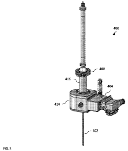
[0043] FIG. 3 illustrates an embodiment of an autostrike
wand mechanism for
striking a microwave plasma torch, according to embodiments of the present
disclosure. The
autostrike wand mechanism 400 may be utilized to strike a plasma torch without
manual
operation by an operator. The plasma torch may be any induction or
electromagnetic wave
plasma torch, including the microwave plasma torch 3 of FIG. 1 and the
microwave plasma
torch 302 of FIGS. 2A-2B. The autostrike wand mechanism 400 may be remotely
controlled
via an operator or via a computerized controller. The function of the
autostrike wand
mechanism may be insertion of an autostrike wand 402 into a plasma torch gas
flow to start
the plasma torch. The wand 402 may comprise an outer shell of quartz, glass,
and/or other
microwave-transparent materials, as described in detail below in reference to
FIG. 7. The
wand 402 may also comprise a hollow core in which a metal wire antenna may be
located.
One or more open apertures may be cut into the wand 402 to allow the metal
wire antenna to
directly contact a plasma torch gas flow under high heat in order to strike
the plasma torch.
The wand 402 may be inserted into the plasma torch gas flow in an orientation
parallel to,
perpendicular to, or at another angle with respect to the gas flow. After
striking the plasma
torch, the wand 402 may be retracted from the plasma torch gas flow to
minimize
contamination of the metal wire into the plasma torch and products, and to
preserve the wand
402 for repeated use.
[0044] The wand 402 may be inserted into and retracted from
the plasma torch
gas flow using a motor 404 to drive one or more friction rollers 406, as shown
in FIG. 4. In
some embodiments, the motor 404 and therefore friction rollers 406 may be
controlled
remotely via an operator or a computerized, automated controller. Thus, the
autostrike wand
mechanism 400 may be used to start plasma torch with no human operator present
in
proximity to the plasma torch for enhanced safety. The autostrike wand 402 may
also be
supported within the autostrike wand mechanism 400 by one or more wand
bearings 408,
which maintain the orientation and integrity of the auto strike wand 402. A
limit switch 410
may be used to sense the wand 402 at a home position.
[0045] FIG. 4 illustrates a cross-sectional view of an
embodiment of an autostrike
wand mechanism for striking a microwave plasma torch, according to embodiments
of the
-12-
CA 03186082 2023- 1- 13
WO 2022/067303
PCT/US2021/071519
present disclosure. The illustrated cross-section of FIG. 4 shows friction
rollers 406, driven
by motor 404. In the illustrated embodiment, the friction rollers 406 may be
driven by motor
404 to move or translate wand 402 vertically up and down. Wand bearing 408 may
secure
the orientation of wand 402 within the autostrike wand mechanism 400.
[0046] FIG. 5 illustrates an embodiment of a motor and
friction roller mechanism
for controlling the motion of an autostrike wand, according to embodiments of
the present
disclosure. In the illustrated embodiment, motor 404 is connected to friction
rollers 406 via a
driveshaft 412, which transmits torque and rotation from motor 404 to friction
rollers 406. In
such a way, friction rollers 406 may convey wand 402 into and out of a plasma
torch in order
to ignite the torch. In some embodiments, friction rollers 406 may be housed
within a wand
mechanism body 414, which may be connected to a wand housing 416, where the
wand
bearing 408 is located. In some embodiments, the wand housing 416 and/or the
wand
mechanism body 414 may be vacuum sealed from the motor and other components.
[0047] FIG. 6 illustrates an embodiment of an upper limit
switch mechanism for
use in a microwave plasma torch with an autostrike wand, according to
embodiments of the
present disclosure. In some embodiments, limit switch 410 may be used as part
of a wand
control system, as a safety interlock, or to sense a home position of the wand
402, outside of
a plasma torch gas flow. A limit switch is an electromechanical device that
consists of an
actuator mechanically linked to a set of contacts. When the wand 402 contacts
the actuator,
the limit switch 410 operates the contacts to make or break an electrical
connection, which
can be transmitted to a controller.
[0048] FIG. 7 illustrates an embodiment of an autostrike
wand for striking a
plasma torch, according to embodiments of the present disclosure. The wand 402
may
comprise an elongate, hollow wand member made substantially of quartz or
another
microwave transparent material, having a closed distal end 421 and an open
proximal end
and one or more apertures 420 extending from a hollow interior 422 of the wand
member to
an exterior 424 of the wand member, the one or more apertures having a
predetermined shape
and size that can vary as required, the hollow wand member being designed for
operable
communication with a plasma torch.
[0049] The wand 402 may also comprise an elongate wire
member or antenna
426 positioned within the interior 422 of the hollow wand member 402 and
extending at least
-13-
CA 03186082 2023- 1- 13
WO 2022/067303
PCT/US2021/071519
from a position proximate the closed distal end 421 and the one or more
openings 420 to a
position outside of the open proximal end, wherein the wire member or antenna
426 is
designed for operable communication through the one or more apertures 420 with
a
particular power source, such as a microwave generator, such that the power
source can he
activated to in turn start the plasma within a microwave plasma torch.
[0050] In some embodiments, the wand 402 may comprise
quartz and/or other
microwave-transparent materials, such as glasses. In some embodiments, the
antenna 426
may comprise one or more metal wires. The wand 402 may enclose the one or more
wires
except at the one or more apertures, which minimizes the risk of having the
one or more
wires slip free and contaminate the plasma torch. In some embodiments, the
antenna may
comprise a metal or a metal alloy. In some embodiments, the antenna 426 may be
fused to
the interior 422 of the wand 402 to keep the antenna fixed in place. For
example, the antenna
425 may be fused by a glass-to-metal oxide bond to the interior 422. The
length of the
antenna 426 may also be varied. For example, in some embodiments, the metal
wire may
extend the entire length of the wand 402. Alternatively, in some embodiments,
the antenna
426 may extend only partially along the length of the wand 402. For example,
the metal wire
may he provided only at the location of one or more apertures 420 in the wand.
In some
embodiments, the antenna length may correspond to a wavelength of an
electromagnetic
wave used in the microwave plasma torch. For example, the antenna length may
comprise
about 1/4 the length of the wavelength of the microwave of the plasma torch,
or a multiple of
1/4 the length of the wavelength. In some embodiments, the antenna length may
comprise
about 1/8, about 1/4, about 3/8. about 1/2, about 3/4, about 7/8, about 1
wavelength or longer
than the microwave of the plasma torch. Without being limited by theory, an
antenna length
of about 1/4 the length of the wavelength or more generates a maximum voltage
across the
antenna. Higher voltage will increase the amount of electrons emitted by wire
into the gas
flow of the plasma torch, such that ionization of gas is maximized to start a
chain reaction,
such that the plasma is ignited. In some embodiments, a shorter antenna length
may be used
depending on the properties of the specific metals used in the antenna.
[0051] In some embodiments, the number of apertures 420 may
not be limited. In
some embodiments, the number, placement, and orientation of the apertures 420
may be
-14-
CA 03186082 2023- 1- 13
WO 2022/067303
PCT/US2021/071519
varied to optimize the efficiency of the striking mechanism and to minimize
contamination of
the antenna 426 into the plasma torch.
[0052] FIG. 8 illustrates another embodiment of an
autostrike wand for striking a
plasma torch, according to embodiments of the present disclosure. As noted
above, the size
orientation and number of apertures 420 may be varied according to the desired
process
condition. The apertures 420 may he circular in shape, as illustrated in FIG.
8.
Additional Embodiments
[0053] In the foregoing specification, the invention has
been described with
reference to specific embodiments thereof. It will, however, be evident that
various
modifications and changes may be made thereto without departing from the
broader spirit
and scope of the invention. The specification and drawings are, accordingly,
to be regarded
in an illustrative rather than restrictive sense.
[0054] Indeed, although this invention has been disclosed
in the context of certain
embodiments and examples, it will be understood by those skilled in the art
that the invention
extends beyond the specifically disclosed embodiments to other alternative
embodiments
and/or uses of the invention and obvious modifications and equivalents
thereof. In addition,
while several variations of the embodiments of the invention have been shown
and described
in detail, other modifications, which are within the scope of this invention,
will be readily
apparent to those of skill in the art based upon this disclosure. It is also
contemplated that
various combinations or sub-combinations of the specific features and aspects
of the
embodiments may be made and still fall within the scope of the invention. It
should be
understood that various features and aspects of the disclosed embodiments can
be combined
with, or substituted for, one another in order to form varying modes of the
embodiments of
the disclosed invention. Any methods disclosed herein need not be performed in
the order
recited. Thus, it is intended that the scope of the invention herein disclosed
should not be
limited by the particular embodiments described above.
[0055] It will be appreciated that the systems and methods
of the disclosure each
have several innovative aspects, no single one of which is solely responsible
or required for
the desirable attributes disclosed herein. The various features and processes
described above
may be used independently of one another, or may be combined in various ways.
All
-15-
CA 03186082 2023- 1- 13
WO 2022/067303
PCT/US2021/071519
possible combinations and subcombinations are intended to fall within the
scope of this
disclosure.
[0056] Certain features that are described in this
specification in the context of
separate embodiments also may be implemented in combination in a single
embodiment.
Conversely, various features that are described in the context of a single
embodiment also
may be implemented in multiple embodiments separately or in any suitable
subcombination.
Moreover, although features may be described above as acting in certain
combinations and
even initially claimed as such, one or more features from a claimed
combination may in some
cases be excised from the combination, and the claimed combination may be
directed to a
subcombination or variation of a subcombination. No single feature or group of
features is
necessary or indispensable to each and every embodiment.
[0057] It will also be appreciated that conditional
language used herein, such as,
among others, -can," -could," -might," -may," -e.g.," and the like, unless
specifically stated
otherwise, or otherwise understood within the context as used, is generally
intended to
convey that certain embodiments include, while other embodiments do not
include, certain
features, elements and/or steps. Thus, such conditional language is not
generally intended to
imply that features, elements and/or steps are in any way required for one or
more
embodiments or that one or more embodiments necessarily include logic for
deciding, with
or without author input or prompting, whether these features, elements and/or
steps are
included or are to be performed in any particular embodiment. The terms
"comprising,"
"including," "having," and the like are synonymous and are used inclusively,
in an open-
ended fashion, and do not exclude additional elements, features, acts,
operations, and so
forth. In addition, the term "or" is used in its inclusive sense (and not in
its exclusive sense)
so that when used, for example, to connect a list of elements, the term "or"
means one, some,
or all of the elements in the list. In addition, the articles "a," "an," and
"the" as used in this
application and the appended claims are to be construed to mean "one or more"
or "at least
one" unless specified otherwise. Similarly, while operations may be depicted
in the drawings
in a particular order, it is to be recognized that such operations need not be
perfoimed in the
particular order shown or in sequential order, or that all illustrated
operations be performed,
to achieve desirable results. Further, the drawings may schematically depict
one more
example processes in the font' of a flowchart. However, other operations that
are not
-16-
CA 03186082 2023- 1- 13
WO 2022/067303
PCT/US2021/071519
depicted may be incorporated in the example methods and processes that are
schematically
illustrated. For example, one or more additional operations may be performed
before, after,
simultaneously, or between any of the illustrated operations. Additionally,
the operations
may be rearranged or reordered in other embodiments.
In certain circumstances,
multitasking and parallel processing may be advantageous. Moreover, the
separation of
various system components in the embodiments described above should not be
understood as
requiring such separation in all embodiments, and it should be understood that
the described
program components and systems may generally be integrated together in a
single software
product or packaged into multiple software products. Additionally, other
embodiments are
within the scope of the following claims. In some cases, the actions recited
in the claims
may be performed in a different order and still achieve desirable results.
[0058]
Further, while the methods and devices described herein may be
susceptible to various modifications and alternative forms, specific examples
thereof have
been shown in the drawings and are herein described in detail. It should be
understood,
however, that the invention is not to be limited to the particular forms or
methods disclosed,
but, to the contrary, the invention is to cover all modifications,
equivalents, and alternatives
falling within the spirit and scope of the various implementations described
and the appended
claims. Further, the disclosure herein of any particular feature, aspect,
method, property,
characteristic, quality, attribute, element, or the like in connection with an
implementation or
embodiment can be used in all other implementations or embodiments set forth
herein. Any
methods disclosed herein need not be performed in the order recited. The
methods disclosed
herein may include certain actions taken by a practitioner; however, the
methods can also
include any third-party instruction of those actions, either expressly or by
implication. The
ranges disclosed herein also encompass any and all overlap, sub-ranges, and
combinations
thereof. Language such as "up to," "at least," "greater than," "less than,"
"between," and the
like includes the number recited. Numbers preceded by a term such as "about"
or
"approximately" include the recited numbers and should be interpreted based on
the
circumstances (e.g., as accurate as reasonably possible under the
circumstances, for example
5%, 10%, 15%, etc.). For example, "about 3.5 mm" includes "3.5 mm." Phrases
preceded by a term such as "substantially" include the recited phrase and
should be
interpreted based on the circumstances (e.g., as much as reasonably possible
under the
-17-
CA 03186082 2023- 1- 13
WO 2022/067303
PCT/US2021/071519
circumstances). For example, -substantially constant" includes "constant."
Unless stated
otherwise, all measurements are at standard conditions including temperature
and pressure.
[0059] As used herein, a phrase referring to "at least one
of" a list of items refers
to any combination of those items, including single members. As an example, -
at least one
of: A, B, or C" is intended to cover: A, B, C, A and B. A and C, B and C, and
A, B, and C.
Conjunctive language such as the phrase -at least one of X, Y and Z," unless
specifically
stated otherwise, is otherwise understood with the context as used in general
to convey that
an item, term, etc. may be at least one of X, Y or Z. Thus, such conjunctive
language is not
generally intended to imply that certain embodiments require at least one of
X, at least one of
Y, and at least one of Z to each be present. The headings provided herein, if
any, are for
convenience only and do not necessarily affect the scope or meaning of the
devices and
methods disclosed herein.
[0060] Accordingly, the claims are not intended to be
limited to the embodiments
shown herein, but are to be accorded the widest scope consistent with this
disclosure, the
principles and the novel features disclosed herein.
-18-
CA 03186082 2023- 1- 13