Note: Descriptions are shown in the official language in which they were submitted.
WO 2022/015360
PCT/US2020/070274
DRAPER HEADER WITH LEAN BAR ASSEMBLY
BACKGROUND OF THE INVENTION
1. Field of the Invention
[0001] The present invention relates to a draper header for
harvesting agricultural
crops.
2. Description of Related Art
[0002] Draper headers for harvesting agricultural crops are
known in the art. Typical
draper headers include a header frame having a front and a rear portion
extenchng laterally
between opposite first and second ends. A first and a second reel support arm
are disposed
adjacent the first and second ends of the header frame, where each of the
first and second reel
support ants extend between a proximal end coupled to the rear portion of the
header frame
and an opposite distal end spaced above the front portion of the header frame.
Typically, a
crop pick-up reel is rotatably coupled between the first and second reel
support arms for
engaging the crops to be harvested, and the crop pick-up reel is often
selectively moveable in
a fore and an aft direction along the reel support arms between the proximal
and distal ends
thereof. Often a lean bar assembly is attached to the header frame for
engaging the crops to
be harvested prior to the crop pick-up reel. However, typical draper headers
known in the art
generally do not maintain a pre-deteimined position of the lean bar assembly
relative the crop
pick-up reel during movement of the crop pick-up reel in the fore and aft
directions along the
reel support arms. Therefore, lean bar assemblies known in the art often
require adjustment as
the crop pick-up reel is moved throughout its range.
SUMMARY OF THE INVENTION
[0003] According to one aspect of the invention, a draper
header is provided for
harvesting agricultural crops. The draper header includes a header frame with
a front and a
rear portion extending laterally between opposite first and second ends. A
first and a second
reel support atm are disposed adjacent the first and second ends of the header
frame, where
each of the first and second reel support arms extend between a proximal end
coupled to the
rear portion of the header frame and an opposite distal end spaced above the
front portion of
the header frame. A crop pick-up reel is rotatably coupled between the first
and second reel
support arms for engaging the crops to be harvested and is selectively
moveable in a fore and
1
CA 03186098 2023- 1- 13
WO 2022/015360
PCT/US2020/070274
an aft direction along the reel support arms between the proximal and distal
ends thereof A
lean bar assembly is coupled to the crop pick-up reel for engaging the crops
to be harvested
prior to the crop pick-up reel, wherein the lean bar assembly is secured at a
predetermined
position relative to the crop pick-up reel to maintain the predetermined
position during
selective movement of the crop pick-up reel in the fore and aft directions
along the reel
support arms.
[0004] According to another aspect of the invention, a draper
header is provided for
harvesting agricultural crops. The draper header includes a header frame with
a front and a
rear portion extending laterally between opposite first and second ends. An
inboard and an
outboard reel support arm are disposed adjacent the first and second ends of
the header frame,
and a center reel support arm is spaced therebetvveen. Each of the inboard,
outboard, and
center reel support arms extend between a proximal end coupled to the rear
portion of the
header frame and an opposite distal end spaced above the front portion of the
header frame. A
first crop pick-up reel is rotatably coupled between the outboard and center
reel support arms
and a second crop pick-up reel is rotatably coupled between the inboard and
center reel
support arms for engaging the crops to be harvested. The first and second crop
pick-up reels
are selectively moveable in a fore and an aft direction along the inboard,
outboard, and center
reel support arms between the proximal and distal ends thereof. A lean bar
assembly is
coupled to each of the first and second crop pick-up reels for engaging the
crops to be
harvested prior tb the first and second crop pick-up reels. At least one of
the lean bar
assemblies is secured at a predetermined position relative to the first and
second crop pick-up
reels to maintain the predetermined position during selective movement of the
first and
second crop pick-up reels in the fore and aft directions along the inboard,
outboard, and
center reel support arms.
BRIEF DESCRIPTION OF THE DRAWINGS
[0005] Advantages of the present disclosure will be readily
appreciated as the same
becomes better understood by reference to the following detailed description
when
considered in connection with the accompanying drawings, wherein:
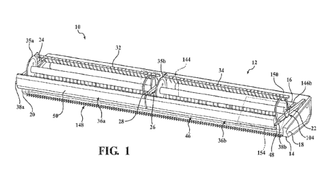
[0006] Figure 1 is a perspective view of a draper header
according to a primary
embodiment of the present invention;
[0007] Figure 2 is a fragmentary side view of the draper header
of Figure 1;
2
CA 03186098 2023- 1- 13
WO 2022/015360
PCT/US2020/070274
[0008] Figure 3 is an fragmentary perspective view of the
draper header of Figure 1
showing a second lean bar assembly coupled to a lateral reel bracket;
[0009] Figure 4 is an enlarged fragmentary perspective view of
the draper header of
Figure 1 showing the second lean bar assembly further secured to the lateral
reel bracket;
[0010] Figure 5 is a fragmentary perspective view of the draper
header of Figure 1
showing a center reel support arm with a center cradle slidably supporting a
first lean bar
assembly and the second lean bar assembly;
[0011] Figure 6 is a fragmentary front view of the draper
header of Figure 1 showing
a medial lean bar support of the first lean bar assembly slidably and matingly
coupled with a
medial lean bar support of the second lean bar assembly;
[0012] Figure 7 is a fragmentary perspective view of the draper
header of Figure 1
further showing the medial lean bar support of the first lean bar assembly
slidably and
matingly coupled with the medial lean bar support of the second lean bar
assembly;
[0013] Figure 8 is an enlarged fragmentary perspective view of
the draper header of
Figure 1 showing the first and second lean bar assemblies secured to a center
reel bracket;
[0014] Figure 9 is an enlarged fragmentary perspective view of
the draper header of
Figure 1 further showing the first and second lean bar assemblies secured to
the center reel
bracket;
[0015] Figure 10 is a side view of the draper header of Figure
1 showing a hydraulic
cylinder extended after moving a first and a second crop pick-up reel and the
first and second
lean bar assemblies in a fore direction;
[0016] Figure 11 is a side view of the draper header of Figure
1 showing the
hydraulic cylinder retracted after moving the first and second crop pick-up
reels and the first
and second lean bar assemblies in an aft direction; and
[0017] Figure 12 is a perspective view of a draper header
according to an alternative
embodiment of the present invention.
3
CA 03186098 2023- 1- 13
WO 2022/015360
PCT/US2020/070274
\DETAILED DESCRIPTION OF THE EMBODIMENTS
[0018] Referring to the Figures, wherein like numerals indicate
like or corresponding
parts throughout the several views, a draper header for harvesting
agricultural crops is shown
generally at 10. The draper header 10 includes a header frame 12 with a front
portion 14 and
a rear portion 16 extending laterally between opposite first and second ends
18, 20. An
inboard reel support arm 22 and an outboard reel support arm 24 are disposed
adjacent the
first and second ends 18, 20 of the header frame 12 with a center reel support
arm 26 spaced
generally equally therebetween. The inboard, outboard, and center reel support
arms 22, 24,
26 each extend between a proximal end 28 coupled to the rear portion 16 of the
header frame
12 and an opposite distal end 30 spaced above the front portion 14 of the
header frame 12, as
shown in Figures 1 through 3. Additionally, although only the inboard reel
support arm is
shown in Figures 2 and 3, it is appreciated that the inboard and outboard reel
support arms are
substantially the same. A first crop pick-up reel 32 is slidably and rotatably
coupled between
the outboard and t enter reel support arms 24, 26 and a second crop pick-up
reel 34 is slidably
and rotatably coupled between the inboard and center reel support arms 22, 26
for engaging
the crops to be harvested. The first and second crop pick-up reels 32, 34 each
extend between
a lateral and a medial end 35a, 35b and are selectively moveable in a fore and
an aft direction
along the inboard, outboard, and center reel support arms 22, 24, 26.
Referring to Figures 1
and 2, a first lean bar assembly 36a is releasably coupled to the first crop
pick-up reel 32 and
a second lean bar assembly 36b is releasably coupled to the second crop pick-
up reel 34. The
first and second lean bar assemblies 36a, 36b engage and forwardly lean the
crops to be
harvested prior to entering the first and second crop pick-up reels 32, 34 to
prevent tangling
of the crops therein. It is to be appreciated that the draper header may
include any suitable
number and arrangement of reel support arms, crop pick-up reels, and lean bar
assemblies
without varying the scope of the invention. For example, the draper header may
include a
single crop pick-up reel and a corresponding lean bar assembly, as shown in
Figure 12,
wherein the crop pick-up reel and lean bar assembly are slidably and rotatably
supported
between a pair of reel support amis.
[0019] Referring to Figures 1 through 3, the first lean bar
assembly 36a includes a
pair of spaced apart lateral and medial lean bar supports 38a, 40a, and the
second lean bar
assembly similarly includes a pair of spaced apart lateral and medial lean bar
supports 38b,
40b. Each of the lateral and medial lean bar supports 38a, 38b, 40a, 40b
extend longitudinally
between a first end 42 and an opposite second end 44. The first and second
lean bar
4
CA 03186098 2023- 1- 13
WO 2022/015360
PCT/US2020/070274
assemblies 36a, 36b also include a crop engagement element 46 extending
laterally between
the first ends 42 of each respective pair of lateral and medial lean bar
supports 38a, 38b, 40a,
40b. The crop engagement elements 46 have a pair of lateral side walls 48 and
a substantially
arcuate forward wall 50 extending therebetween for engaging the crops to be
harvested, as
shown in Figures 1 and 2. Referring to Figure 2, the lateral side walls 48 of
each crop
engagement element 46 have a plurality of vertically extending slots 52 for
adjustably
coupling to the lateral and medial lean bar supports 38a, 38b, 40a, 40b as is
described in
further detail in the paragraphs below. It is to be appreciated that the crop
engagement
elements of each lean bar assembly may take any suitable shape or arrangement
to engage the
crops to be harvested without limiting the scope of the invention. Referring
to Figure 1, the
second ends 44 of the lateral and medial lean bar supports 38a, 40a of the
first lean bar
assembly 36a are releasably coupled to the first crop pick-up reel 32, and the
second ends 44
of the lateral and medial lean bar supports 38b, 40b of the second lean bar
assembly 36b are
releasably coupled to the second crop pick-up reel 34. The first and second
lean bar
assemblies 36a, 36b are therefore secured at a predetermined position relative
to the first and
second crop pick-up reels 32, 34 and maintain the predetermined position
during selective
movement of the first and second crop pick-up reels 32, 34 in the fore and the
aft directions
along the inboard, outboard, and center reel support arms 22, 24, 26.
[0020] Referring to Figure 3, the lateral lean bar supports
38a, 38b each have a
generally U-shaped cross-section defined by a horizontal bottom side 54
extending laterally
between an upwardly-extending outer side wall 56 and an upwardly-extending
inner side wall
58. A longitudinally extending slot 60 is disposed on the inner side walls 58
of each lateral
lean bar support 38a, 38b adjacent the first ends 42 thereof for adjustably
coupling to the
respective crop engagement elements 46. Referring to Figure 4, a tab 62
extends upwardly
from the bottom sides 54 of each lateral lean bar support 38a, 38b at the
second ends 44
thereof. A post 64 further extends longitudinally from each tab 62 for
releasably coupling the
lateral lean bar supports 38a, 38b to the respective first and second crop
pick-up reels 32, 34.
[0021] Referring to Figures 5 and 6, the medial lean bar
support 40b of the second
lean bar assembly 36b is slidably and matingly coupled within the medial lean
bar support
40a of the first lean bar assembly 36a for reducing space therebetween and
facilitating easy
removal of the first and second lean bar assemblies 36a, 36b from the draper
header 10.
However, it is to be appreciated that the medial lean bar supports may couple
in any suitable
CA 03186098 2023- 1- 13
WO 2022/015360
PCT/US2020/070274
arrangement, or may omit coupling entirely, without varying the scope of the
invention. The
medial lean bar supports 40a, 40b each have a generally J-shaped cross-section
mirrored
relative to one another at the first ends 42 thereof, as shown in Figure 6.
The generally J-
shaped cross-sections are defined by a horizontal bottom side 66 extending
between an
upwardly-extending shortened side wall 68 and an upwardly-extending full side
wall 70.
Additionally, the generally J-shaped cross-section of each medial lean bar
support 40a, 40b
extends to a full U-shaped cross-section adjacent the second ends 44 thereof
for added
robustness and stability, as shown in Figure 7. A longitudinally extending
slot 72 is further
disposed on the full side wall 70 of each medial lean bar support 40a, 40b
adjacent the first
ends 42 thereof for adjustably coupling to the respective crop engagement
elements 46.
Referring to Figures 8 and 9, a post 74 extends longitudinally from the second
end 44 of the
medial lean bar support 40b of the second lean bar assembly 36b. The medial
lean bar
support 40a of the first lean bar assembly 36a has a tab 76 extending upwardly
from the
bottom side 66 at the second end 44 thereof. A corresponding opening 78 in the
tab 76
receives the post 74 to rcleasably couple the medial lean bar supports 40a,
40b to the first and
second crop pick-up reels 32, 34.
[0022] Referring to Figures 3, 5, and 6, a plurality of
coupling pins 80 extend
between the vertically extending slots 52 on the lateral side walls 48 and the
longitudinally
extending slots 60, 72 on the lateral and medial lean bar supports 38a, 38b,
40a, 40b for
adjustably coupling the crop engagement elements 46 therebetween. The
predetermined
position of the first and second lean bar assemblies 36a, 36b relative to the
first and second
crop pick-up reels 32, 34 is therefore adjustable and selectable by
manipulating each crop
engagement element 46 in the fore and aft directions along the longitudinally
extending slots
60, 72 of each respective pair of lateral and medial lean bar supports 38a,
38b, 40a, 40b.
[0023] Referring to Figures 2 and 3, the inboard and outboard
reel support arms 22,
24 have a generally U-shaped cross-section inverted relative to the header
frame 12 that is
defined by a horizontal top side 82 extending between a pair of downwardly-
extending lateral
side walls 84. A lateral cradle 86 is coupled to each of the inboard and
outboard reel support
arms 22, 24 adjacent the distal ends 30 thereof, as shown in Figure 3. Each
lateral cradle 86
has a generally U-shaped cross-section defined by a horizontal bottom side 88
extending
laterally between a pair of upwardly-extending lateral side walls 90. The
lateral side walls 90
matingly couple within and are secured to the lateral side walls 84 of the
inboard and
6
CA 03186098 2023- 1- 13
WO 2022/015360
PCT/US2020/070274
outboard reel support arms 22, 24 such that the bottom sides 8E: of the
lateral cradles 86 are
suspended below the inboard and outboard reel support arms 22, 24, as shown in
Figures 2
and 3. However, it is to be appreciated that the inboard and outboard reel
support aims and
the lateral cradles may have any number of potential arrangements and shapes
without
varying the scope of the invention. The lateral cradle 86 attached to the
outboard reel support
arm 24 slidably receives and supports the lateral lean bar support 38a of the
first lean bar
assembly 36a therethrough during selective movement of the first and second
crop pick-up
reels 32, 34 in the fore and aft directions. Similarly, the lateral cradle 86
attached to the
inboard reel support aim 22 slidably receives and supports the lateral lean
bar support 38b of
the second lean bar assembly 36b during selective movement of the first and
second crop
pick-up reels 32, 34 in the fore and aft directions.
[0024] Referring to Figures 5 through 7, the center reel
support aim 26 has opposite
lateral side walls 92 extending between a horizontal top side 94 and a
horizontal bottom side
96. A center cradle 98 is coupled to the center reel support arm 26 at the
distal end 30 thereof,
as shown in Figure 5. The center cradle 98 has a pair of lateral side walls
100 affixed to and
extending outwardly and downwardly from the lateral side walls 92 of the
center reel support
arm 26 to a horizontal bottom side 102, as shown in Figures 6 and 7. However,
it is to be
appreciated that the center reel support arm and the center cradle may have
any number of
potential arrangements and shapes without varying the scope of the invention.
The center
cradle 98 slidably receives and supports the medial lean bar supports 40a, 40b
of the first and
second the lean bar assemblies 36a, 36b therethrough during selective movement
of the first
and second crop pick-up reels 32, 34 in the fore and aft directions.
[0025] A lateral reel bracket 104 is slidably attached to each
inboard and outboard
reel support aim 22, 24, as shown in Figures 1 and 2, and a center reel
bracket 106 is slidably
attached to the center reel support arm 26, as shown in Figures 1 and 5. The
first crop pick-up
reel 32 is rotatably and slidably supported between the center reel bracket
106 and the lateral
reel bracket 104 attached to the outboard reel support arm 24. Similarly, the
second crop
pick-up reel 34 is rotatably and slidably supported between the center reel
bracket 106 and
the lateral reel bracket 104 attached to the inboard reel support alai 22. The
lateral and center
reel brackets 104, 106 additionally couple with the first and second lean bar
assemblies 36a,
36b for corresponding slideable movement of the first and second lean bar
assemblies 36a,
36b with the first and second crop pick-up reels 32, 34.
7
CA 03186098 2023- 1- 13
WO 2022/015360
PCT/US2020/070274
[0026] Referring to Figures 2 through 4, each lateral reel
bracket 104 extends
between an upper portion 108 and a lower portion 110 with a substantially
planar engagement
surface 112 disposed therebetween. The upper portion 108 of each lateral reel
bracket 104
includes a pair of walls 114 extending upwardly from the engagement surface
112, the walls
114 forming a semiannular recess 116 for cradling an annular coupling element
118. The
annular coupling elements 118 rotatably couple to the lateral ends 35a of the
first and second
crop pick-up reels 32, 34, as shown in Figure 2. The lower portion 110 of each
lateral reel
bracket 104 includes a pair of laterally spaced apart legs 120 extending
downwardly from the
engagement surface 112, as shown in Figures 2 through 4. The engagement
surface 112 of
each lateral reel bracket 104 slidably engages the horizontal top sides 82 of
the inboard and
outboard reel support arms 22, 24, and the legs 120 straddle the lateral side
walls 84 of the
inboard and outboard reel support arms 22, 24 for slideable movement of the
lateral reel
brackets 104 along the inboard and outboard reel support arms 22, 24.
[0027] The legs 120 of each lateral reel bracket 104 extend
downwardly past the
lateral side walls 84 of the inboard and outboard reel support arms 22, 24 and
terminate at a
lower end 122, as shown in Figures 3 and 4. A bracket hole 124 is
correspondingly disposed
on each leg 120 adjacent the lower ends 122 thereof A mounting bracket 126, as
shown in
Figure 4, extends between and is fixedly secured to the corresponding bracket
holes 124.
Each mounting bracket 126 has a substantially planar rear wall 128 extending
substantially
vertically from the corresponding bracket holes 124 and laterally between the
legs 120 with
an opening 130 therethrough. The openings 130 in the mounting brackets 126
each receive
one of the posts 64 extending from the lateral lean bar supports 38a, 38b to
releasably couple
the lateral lean bar support 38a of the first lean bar assembly 36a to the
first crop pick-up reel
32, and to releasably couple the lateral lean bar support 38b of the second
lean bar assembly
36b to the second crop pick-up reel 34. Each mounting bracket 126 further
includes an
alignment element 134 extending transversely from the rear wall 128 thereof.
The alignment
elements 134 have a generally U-shaped cross-section inverted relative to the
header frame
12 for nesting of the outer and inner side walls 56, 58 of the lateral lean
bar supports 38a, 38b
within each respective alignment element 134, thus aiding in proper alignment
of the lateral
lean bar supports 38a, 38b and posts 64 relative to the mounting brackets 126.
However, it is
to be appreciated that the mounting brackets may have any number of potential
arrangements
and shapes for coupling with the lateral lean bar supports without varying the
scope of the
invention. A latch pin 132 is operatively engaged with each of the posts 64 to
further secure
8
CA 03186098 2023- 1- 13
WO 2022/015360
PCT/US2020/070274
the lateral lean bar supports 38a, 38b to the first and second crop pick-up
reels 32, 34, as
shown in Figure 4.
[0028] Referring to Figures 5 and 8, the center reel bracket
106 includes an
engagement surface 136 extending between a pair of downwardly-extending outer
side walls
138 which terminate at a lower end 140. The engagement surface 136 slidably
engages the
horizontal top side 94 of the center, reel support arm 26, and each of the
outer side walls 138
straddle the lateral side walls 92 of the center reel support aim 26. Each of
the outer side
walls 138 includes an annular coupling element 139 disposed thereon for
rotatably coupling
with the medial ends 35b of the first and second crop pick-up reels 32, 34, as
shown in Figure
5. A reel drive assembly known in the art is operatively coupled between the
center reel
bracket 106 and the first and second crop pick-up reels 32, 34 for rotatably
driving the first
and second crop pick-up reels 32, 34 to engage and harvest the crops. One such
reel drive
assembly is described in U.S. Patent No. 6,591,598, the disclosure of which is
hereby
incorporated by reference in its entirety. Referring to Figures 8 and 9, a
mounting bracket 142
extends between the lower ends 140 of the side walls 138 and includes an
opening 144
therethrough. The opening 144 receives the post 74 extending from the medial
lean bar
support 40b of the second lean bar assembly 36b and a latch pin 132 is
operatively engaged
with the post 74 to releasably couple the medial lean bar supports 40a, 40b to
the first and
second crop pick-up reels 32, 34.
[0029] Referring to Figures 1, 10, and 11, a first hydraulic
cylinder 146a is
operatively coupled between the proximal end 28 of the inboard reel support
arm 22 and the
upper portion 108 of the lateral reel bracket 104 disposed on the inboard reel
support ami 22,
and a second hydraulic cylinder 146b is operatively coupled between the
proximal end 28 of
the outboard reel support arm 24 and the upper portion 108 of the lateral reel
bracket 104
disposed on the outboard reel support arm 24. Additionally, referring to
Figures 1 and 6, a
third hydraulic cylinder 146c is operatively coupled between the proximal end
28 of the
center reel support ami 26 and the center reel bracket 106. However, it is to
be appreciated
that the draper header may include any suitable number and arrangement of
hydraulic
cylinders or may instead include a suitable alternative mechanism for
providing slideable
movement of the crop pick-up reels without varying the scope of the invention.
The first,
second, and third hydraulic cylinders 146a, 146b, 146c are simultaneously and
correspondingly extendable, as shown in Figure 10, and retractable, as shown
in Figure 11, to
9
CA 03186098 2023- 1- 13
WO 2022/015360
PCT/US2020/070274
move the center reel bracket 106 and the lateral reel brackets 104, and
therefore, the first and
second crop pick-up reels 32, 34 in the fore and aft directions along the
inboard, outboard,
and center reel support arms 22, 24, 26 between the proximal and distal ends
28, 30 thereof
The first and second lean bar assemblies 36a, 36b, slidably supported by the
lateral and center
cradles 86, 98 and secured to the lateral and center reel brackets 104, 106,
move with the first
and second crop pick-up reels 32, 34 in the fore and aft directions to
maintain the
predetermined position relative to the first and second crop pick-up reels 32,
38, as shown in
Figures 10 and 11.
[0030] Referring to Figures 1, 10, and 11, the draper header 10
further includes a
cutter bar assembly 148 operatively extending across the front portion 14 of
the header frame
12 for cutting the crops to be harvested. A rear wall 150 extends vertically
from the rear
portion 16 of the header frame 12 between the first and second ends 18, 20
thereof. An
opening 152 extends through the rear wall 150 of the header frame 12 for
transferring crops
away from the draper header 10, generally for further processing by an
agricultural machine
such as a combine or for creation of windrows by a swather. However, it is to
be appreciated
that the crops may be transferred from the draper header for any number of
other suitable
purposes not listed herein without varying the scope of the invention. At
least one tensioned
draper belt assembly 154 is operatively coupled between the first and second
ends 18, 20 of
the header frame 12. The draper belt assembly 154 is adapted and arranged for
transporting
cut crops engaged by the first and second crop pick-up reels 32, 34 to the
opening 152 in the
rear wall 150 for transfer of the crops away from the draper header 10.
[0031] Referring to operation of the draper header 10, a user
first selects the
predetermined position of the first and second lean bar assemblies 36a, 36b
relative to the
first and second crop pick-up reels 32, 34 to optimally position the first and
second lean bar
assemblies 36a, 36b for the specific crops to be harvested. The predetermined
position is
selectable by manipulating each crop engagement element 46 in the fore and aft
directions
along the longitudinally extending slots 60, 72 of each respective pair of
lateral and medial
lean bar supports 38a, 38b, 40a, 40b. Once the predeteiniined position has
been selected, the
first, second, and third hydraulic cylinders 146a, 146b, 146c may be extended
and retracted as
desired, as shown in Figures 10 and 11, to move the first and second crop pick-
up reels 32, 34
in the fore and aft directions along the inboard, outboard, and center reel
support arms 22, 24,
26 for optimal reel positioning for the specific crops to be harvested.
Movement of the first
CA 03186098 2023- 1- 13
WO 2022/015360
PCT/US2020/070274
and second crop pick-up reels 32, 34 in the fore and aft directions
simultaneously and
correspondingly moves the first and second lean bar assemblies 36a. 36b in the
fore and aft
directions therewith while maintaining the predetermined position. The crops
to be harvested
first engage the first and second lean bar assemblies 36a, 361) and are
therefore forwardly
leaned or bent prior to entering the first and second crop pick-up reels 32,
34 to prevent
tangling of crops within the first and second crop pick-up reels 32, 34. After
engaging the
first and second lean bar assemblies 36a, 36b, the crops engage the first and
second crop
pick-up reels 32, 34 and are cut by the cutter bar assembly 148. Once cut by
the cutter bar
assembly 148 and positioned by the first and second crop pick-up reels 32, 34,
the cut crops
are transported by the draper belt assembly 154 to the opening 152 in the rear
wall 150 of the
header frame 12 for further processing or windrow creation.
[0032] To remove the first and second lean bar assemblies 36a,
36b from the draper
header 10 for storage or use of the draper header 10 without the lean bar
assemblies 36a, 36b,
the latch pins 132 are first disengaged from each post 64, 74 extending from
the medial and
lateral lean bar supports 38a, 38b, 40a, 40b, as shown in Figures 4, 8, and 9.
The second lean
bar assembly 36b is then removed first from the draper header 10. The lateral
lean bar
support 38b is first removed from the lateral cradle 86 coupled to the inboard
reel support
arm 22, and the post extending therefrom 64 is correspondingly removed from
the opening
130 in the mounting bracket 126 secured to the lateral reel bracket 104, as
shown in Figures 3
and 4. The medial lean bar support 40b is simultaneously removed from the
center cradle 98
and from within the medial lean bar support 40a of the first lean bar assembly
36a. The post
74 extending from the medial lean bar support 40b of the second lean bar
assembly 36b is
also removed from the opening 78 disposed in the second end 44 of the medial
lean bar
support 40a of the first lean bar assembly 36a and the opening 144 in the
mounting bracket
142 of the center reel bracket 106, as shown in Figures 8 and 9. Then, the
first lean bar
assembly 36a is subsequently removed from the draper header 10. The lateral
lean bar
support 38a is removed from the lateral cradle 86 coupled to the outboard reel
support arm
24, and the post extending therefrom 64 is removed from the opening 130 in the
mounting
bracket 126 secured to the lateral reel bracket 104, as shown in Figures 2 and
3. The medial
lean bar support 40a of the first lean bar assembly 36a is simultaneously
removed through the
center cradle 98, and the first and second lean bar assemblies 36a, 36b are
therefore fully '
detached from the draper header 10. The same steps are followed in a
substantially reverse
11
CA 03186098 2023- 1- 13
WO 2022/015360
PCT/US2020/070274
order for re-attaching the first and second lean bar assemblies 36a, 36b to
the draper header
10.
[0033] The invention has been described in an illustrative
maimer, and it is to be
understood that the terminology which has been used is intended to be in the
nature of words
of description rather than of limitation. Directional references employed or
shown in the
description, figures or claims, such as top, bottom, upper, lower, upward,
downward,
lengthwise, widthwise, longitudinal, lateral, and the like, are relative terms
emplOyed for ease
of description and are not intended to limit the scope of the invention in any
respect. Many
modifications and variations of the present invention are possible in light of
the above
teachings. It is, therefore, to be understood that within the scope of the
appended claims, the
invention may be practiced other than as specifically described.
12
CA 03186098 2023- 1- 13