Note: Descriptions are shown in the official language in which they were submitted.
CA 03186884 2022-12-09
WO 2021/252811
PCT/US2021/036886
QUANTIZATION AND ENTROPY CODING OF
PARAMETERS FOR A LOW LATENCY AUDIO CODEC
CROSS-REFERENCE TO RELATED APPLICATIONS
This application claims priority to U.S. Provisional Application Nos.
63/037,784 and
63/194,010, filed June 11, 2020, and May 27, 2021, respectively, each of which
is
incorporated by reference in its entirety.
TECHNICAL FIELD
The present disclosure is directed to the general area of entropy coding of
parameters
(side information) for low latency audio codecs (coders/decoders) and
mechanisms to achieve
.. parameter bit rate targets by iteratively refining the parameter bit rate
using a range of
quantization and entropy coding techniques.
BACKGROUND
When the frame period (frame size) of an audio codec (coder/decoder)
approaches 20
milliseconds (ms) or less, the audio essence is updated in short frame sizes.
If one were to
follow the approach of updating both the audio essence and parameters every
frame, the side
information for each frame would also be embedded and transmitted at the same
rate.
However, it is generally known in the field that the side information does not
need to
be updated that frequently. For example, spatial parameters could be generally
calculated and
updated, e.g., every 40 ms. For codecs with frame periods of 40 ms or longer,
this generally
.. means that the parameter update rate is in line with the frame rate, and
thus parameters could
be encoded in each frame independently. However, in codecs with short frame
periods, e.g.,
below 40 ms, this means that the parameters would be effectively oversampled
if they are all
included in each and every frame.
Thus, broadly speaking, the focus of this present disclosure is to propose
mechanisms
to minimize the side information (or sometimes also referred to as the
parameters) as much as
possible, yet to retain a high frame update rate for the audio essence.
1
CA 03186884 2022-12-09
WO 2021/252811
PCT/US2021/036886
SUMMARY
In view of the above, the present disclosure generally provides a method of
frame-
wise encoding metadata for an input signal, as well as a corresponding
program, computer-
readable storage medium, and apparatus, having the features of the respective
independent
claims.
According to an aspect of the disclosure, a method of frame-wise encoding
metadata
for an input signal is provided. In particular, the metadata may be computed
or calculated
(e.g., extracted) from the input (audio or video) signal by using a suitable
codec
(coder/decoder). Generally speaking, the metadata may be used to regenerate
the input signal
at the decoder side. The metadata may comprise a plurality of at least
partially interrelated
parameters calculable from the input signal. That is to say, at least some of
the parameters of
the input signal may be calculated (e.g., generated or regenerated) in
dependence on at least
some of the other parameters, such that, depending on various circumstances,
not all of the
parameters have to be always transmitted in plain.
Particularly, the method may comprise/involve, for each frame, iteratively
performing, by using a looping process, steps of: determining a processing
strategy from a
plurality of processing strategies for calculating and quantizing the
parameters; calculating
and quantizing the parameters based on the determined processing strategy to
obtain
quantized parameters; and encoding the quantized parameters. Since the looping
process is
generally directed to (among others) the processing related to the
quantization, in some cases,
the looping process may also be referred to as a quantization loop (or simply
loop for short).
In a similar manner, since the processing strategy is also generally directed
to (among others)
the processing related to the quantization, in some cases, the processing
strategy may also be
referred to as a quantization strategy (or, in some other cases,
interchangeably as a
quantization scheme). Further, it is to be noted that the encoding process may
use any
suitable coding procedure, including but is not limited to, entropy coding
(e.g., Huffman or
Arithmetic coding) or without entropy coding (e.g., base2 coding). Any other
suitable coding
mechanism may be adopted, depending on various implementations and/or
requirements.
As can be understood and appreciated by the skilled person, the plurality of
processing strategies for calculating and quantizing the parameters may be
provided in any
suitable manner, such as, predefined or preconfigured. Accordingly, the
processing strategy
may also be determined, from the plurality of processing strategies, in any
suitable manner.
For instance, depending on a (current) bitrate requirement, a suitable
processing strategy may
2
CA 03186884 2022-12-09
WO 2021/252811
PCT/US2021/036886
be selected out of the plurality of processing strategies, such that a
resulting bitrate after
performing the calculation, quantization and encoding (e.g., with or without
entropy coding)
based on the so selected processing strategy meets the (current) bitrate
requirement. Notably,
since the bitrate requirement may change from time to time (e.g., from frame
to frame), the
processing strategy so determined may also be different for each or some
frames.
In particular, each one of the plurality of processing strategies may comprise
a
respective first indication that is indicative of an ordering (or a sequence)
related to the
calculation and quantization of individual parameters. That is to say, the
first indication may
comprise sequence information indicating when and in which order the
individual parameters
are calculated and quantized. As an example (but not as limitation), the first
indication may
comprise information indicating that all the parameters are calculated first
before any of them
are being quantized.
More particularly, the processing strategy is determined based on at least one
bitrate
threshold. As can be understood and appreciated by the skilled person, the
bitrate threshold(s)
may be for example predefined or preconfigured, depending on various
implementations
and/or requirements.
Configured as described above, broadly speaking, the proposed method of the
present
disclosure may be seen as introducing the concept of an iterative and stepwise
approach to
select an optimal parameter quantization scheme/strategy that generally
searches for a 'best'
(or optimal) quantization scheme from multiple alternatives. It is
nevertheless to be noted
that, in the present case, the term 'best' may not necessarily have to be the
quantization
scheme with the lowest (resulting) parameter bit rate (i.e., after
quantization and possible
encoding), but may be seen as one that could mitigate loss of state for the
decoder. As can be
understood by the skilled person, generally speaking, decoder "state" refers
to the history of
information that the decoder retains from previous frames in order to be able
to correctly
decode the current frame. For example (but not as limitation), in some cases,
the encoder side
may adopt a so-called time-differential encoding. However, the use of time-
differential
coding may generally exhibit the downside primarily in the fact that there is
typically frame
to frame state introduced which can present problems when, during
transmission, the audio
stream might undergo packet loss. In this case, both audio and parameters
related to the audio
may be lost during transmission, such that any parameters which have been
updated with
time-differential coding may experience multiple subsequent frames of
potential artefacts. In
this sense, the above-mentioned mitigation of loss of state is referring to an
attempt of
avoiding time-differential coding where possible, so that the decoder does not
need to rely on
3
CA 03186884 2022-12-09
WO 2021/252811
PCT/US2021/036886
metadata received in previous frames to decode the current frame's metadata.
And when
time-differential coding is required, that it be done in such a way that the
system recovers
quickly from packet loss. Specifically, by carefully choosing an appropriate
quantization
scheme as described in the present disclosure, the above illustrated
undesirable behavior
relating to the packet loss can be limited (mitigated) as much as possible.
Put differently, the
present disclosure generally proposes an encode (encoder side) mitigation that
involves an
iterative selection process for the quantization and (with or without entropy)
encoding which
attempts to minimize the extent to which packet loss artefacts may be
introduced for example
because of the time-differential coding being used.
In some examples, the processing strategy may be determined such that a
(resulting)
bit rate of the encoded quantized parameters is equal to or less than the
(metadata/parameter)
bitrate threshold. As such, the resulting bitrate after quantization and
coding using the
determined (e.g., selected) processing strategy is within the (at least one)
bitrate threshold,
thereby meeting the bitrate requirement for example agreed upon beforehand or
pre-
determined by a standardization specification.
In some examples, each of the plurality of processing strategies may further
comprise
a respective second indication indicative of information for performing the
quantization of
the parameters.
In some examples, the information for performing the quantization of the
parameters
comprises respective quantization ranges and/or quantization levels for the
plurality of
parameters. For example, the information may relate to maximum value, minimum
value,
number of quantization levels, or any other suitable value desired for each of
the respective
parameters (e.g., a respective one per parameter type). Generally speaking, as
can be
understood and appreciated by the skilled person, these quantization related
values/parameters provide or define coarser or finer quantization overall, and
correspondingly accompanying better or worse spatial reproduction. As can be
understood
and appreciated by the skilled person, broadly speaking, some (quantization)
parameters are
generally considered to be more sensitive to quantization than others, and
there may generally
not be an absolute fine/coarse quantization methodology for all parameters.
Configured as above, the plurality of processing strategy may be seen as each
comprising a first (part/portion of) indication with regard to the
ordering/sequence relating to
the calculation and quantization; and a second (part/portion of) indication
with regard to the
actual quantization process. By carefully designing the processing strategy
(e.g., different
combinations of first indication and second indication), various bitrate
4
CA 03186884 2022-12-09
WO 2021/252811
PCT/US2021/036886
configurations/requirements may be targeted for example for different use
cases or scenarios,
in an efficient and flexible manner. Specifically, in some cases, there may
exist one
processing strategy (e.g., the coarsest quantization strategy among the
plurality of
quantization strategies) that may be considered to be guaranteed to be less
than (or equal to)
the target bitrate threshold.
In some examples, the encoding of the parameters may involve time- and/or
frequency-differential coding. Broadly speaking, a single metadata parameter
may be
quantized from a continuous numerical value to an index representing a
discrete value. In
non-differential coding, the information that is coded for that metadata
parameter corresponds
directly to that index. Notably, the term "non-differential coding" used in
the present
disclosure may refer to non time-differential coding, non frequency-
differential coding, or
non-differential coding of all kinds as appropriate, as will be understood and
appreciated by
the skilled person. In time-differential coding, the information that is coded
is the difference
between the index of that metadata parameter from the current frame, and the
index of the
same metadata parameter from the previous frame. As will be understood and
appreciated by
the skilled person, the above illustrated general concept of time-differential
coding may be
further extended, e.g., to a plurality of frequency bands. Accordingly, the
metadata parameter
may be extended similarly, e.g., to a plurality of parameters respectively
corresponding to
(each of) the plurality of frequency bands, as appropriate. Frequency-
differential coding
follows a similar principle, but the coded difference is between one frequency
band's
metadata of the current frame and another frequency band's metadata of the
current frame (as
opposed to the current frame minus the previous frame in time-differential
coding). As a
simple example (but not as limitation), assuming a0, al, a2 and a3 to denote
parameters
indices in 4 frequency bands of a particular frame, then, in one example
implementation, the
frequency-differential indices can be a0, a0-al, al-a2, a2-a3. As will be
appreciated by the
skilled person, the general idea behind the (time- and/or frequency-)
differential coding is that
metadata may typically change slowly from frame to frame, or from frequency-
band to
frequency-band, so that even if the original value of the metadata was large,
the difference
between it and the previous frame's metadata, or difference between it and
other frequency
band's metadata, would likely be small. This is advantageous because,
generally, parameters
with statistical distributions that tend towards zero can be coded using fewer
bits.
In some examples, the processing strategy determined for a current frame may
be
different from the processing strategy determined for a previous frame, and
accordingly, the
encoding of the parameters may involve time-differential coding across the
different
5
CA 03186884 2022-12-09
WO 2021/252811
PCT/US2021/036886
processing strategies. That is to say, in certain cases where different
processing strategies are
determined (e.g., for different frames of the input signal), the method of the
present
disclosure is still able to encode the parameters, for example by involving
time-differential
coding across those different processing strategies.
As indicated above, the plurality of processing strategies may each comprise a
respective first indication that is indicative of an ordering (or a sequence)
related to the
calculation and quantization of individual parameters.
In some examples, the first indication may comprise information indicating
that all of
the parameters are calculated before being quantized.
In some examples, the first indication may comprise information indicating
that the
parameters are individually calculated and then quantized one after another in
sequence. In
particular, at least one parameter of the plurality of parameters may be
calculated based on
another quantized parameter of the plurality of parameters. As an example but
not as
limitation, assuming in total three parameters to be calculated and quantized,
then the first
parameter may be calculated first (from the input signal) and then quantized;
while the
second parameter may be calculated based on the (quantized) first parameter
and then the
second parameter itself is quantized; and finally, the third parameter is
calculated based on
the (quantized) first parameter and/or the (quantized) second parameter, and
then quantized.
In one example, the third parameter is calculated based on the quantized first
and second
parameters.
In some examples, the first indication may comprise information indicating
that all of
the parameters are calculated before any parameter is quantized; and
particularly, at least one
of the parameters is recalculated, based on another quantized parameter, and
the recalculated
parameter is quantized. Still taking the above assumption of three parameters
as an example,
all the parameters are calculated first, and then the first and second
parameters are quantized;
afterwards, the third parameter is recalculated, e.g., based on the quantized
second
parameters, and then the third parameter is quantized based on the
recalculated value.
In some examples, the method may further comprise, before encoding the
quantized
parameters, mapping indices of the quantized parameters from the previous
frame to that of
the current frame. In other words, if a different processing strategy
(quantization scheme,
e.g., in terms of different quantization levels and/or sequences) is
determined (e.g.,
selected/chosen), (quantization) indices from the previous frame that were
quantized with a
different quantization scheme are mapped to those of the current frame.
Notably, this allows
time-differential coding between frames without resorting to having to send a
non-differential
6
CA 03186884 2022-12-09
WO 2021/252811
PCT/US2021/036886
frame each time quantization scheme is changed, thereby further improving the
overall
coding efficiency and flexibility.
In some possible implementations, the mapping of the indices may be performed
based on a formulae: indexcur = round(indexpr, x (quant_IvIcur ¨ 1)/
(quant_IvIprev 1)), wherein index, is the indices of the current frame after
mapping,
indexpr, is the index of the previous frame, quant_/v/cur is the quantization
level of the
current frame and quant_IvIprev is the quantization level of the previous
frame.
As a simple illustrative example, let the quantization range be 0 to 2, and
let the
previous quantization levels be 11. In the case of uniform quantization, this
would generally
mean that each quantization step would be 0.2. Further, let the current
quantization levels be
21, which means that each quantization step is 0.1 with uniform quantization.
Based on these
assumptions, if a quantized value in the previous frame was 0.4, then with 11
uniform
quantization levels, one would get the following previous index indexprev = 2.
The mapping
provides the quantized indices of the previous frame's metadata as if it were
quantized using
the current frame's quantization levels. Thus, in this example, if the
quantization levels in the
current frame are 21, then the quantized value 0.4 would be mapped to index,r
= 4. Once
mapped indices are computed, the difference between the current frame and
previous frame
indices is calculated, and this difference is encoded. Analogous or similar
approaches may
also be applied to the frequency-differential coding, if needs be, as will be
understood and
appreciated by the skilled person.
It is to be noted that the above formulae and the respective example are
merely
provided for illustrative purpose only, any other suitable mechanism (e.g., a
lookup table,
etc.) may be adopted for performing the mapping of indices, as will be
understood and
appreciated by the skilled person.
In some examples, the at least one bitrate threshold may comprise a target
bitrate
threshold. Accordingly, the looping process may involve steps of: quantizing
and encoding
the parameters in a non-differential and/or frequency-differential manner with
an entropy
coder in accordance with the (determined) processing strategy; estimating
(e.g., calculating) a
first parameter bitrate for the encoded parameters; and if the first parameter
bitrate is less
.. than or equal to the target bitrate threshold, exiting the looping process.
Particularly, in some
possible implementations, the first parameter bitrate may be estimated
(calculated) from the
minimum of the non-differential and the frequency-differential coding schemes
coded with
(trained) entropy coders. As will be understood and appreciated by the skilled
person, the
7
CA 03186884 2022-12-09
WO 2021/252811
PCT/US2021/036886
entropy coders may be trained in any suitable manner, e.g., in order to be
adapted to
individual coding schemes. For instance, in some possible implementations, the
training of
the entropy coders may involve developing probability models based on metadata
calculated
from a large set of input signals. The particular signals chosen for
developing these models
are expected to be representative of the types of signals expected to be
passed through the
system in everyday use. As such, metadata from other similar signals ought to
be encoded as
efficiently as possible. In short, generally speaking, this training is about
adapting the entropy
coders to have maximum efficiency with the expected probability distribution
of the
parameters.
In some examples, the looping process may further involve steps of: if the
first
parameter bitrate is larger than the target bitrate threshold, quantizing and
encoding the
parameters in a non-differential manner with no entropy in accordance with the
processing
strategy; estimating a second parameter bitrate for the encoded parameters;
and if the second
parameter bitrate is less than or equal to the target bitrate threshold,
exiting the looping
process.
In some examples, the looping process may further involve steps of: if the
second
parameter bitrate is larger than the target bitrate threshold, quantizing and
encoding the
parameters in a time-differential manner with the (trained) entropy coder in
accordance with
the processing strategy; estimating a third parameter bitrate for the encoded
parameters; and
if the third parameter bitrate is less than or equal to the target bitrate
threshold, exiting the
looping process.
In some examples, the time-differential quantization and encoding may be
performed
on a subset of the parameters in a frequency interleaved manner with respect
to a previous
frame. Particularly, as can be understood and appreciated by the skilled
person, the frequency
interleaved manner may generally refer to cases where different frequency
bands (e.g.,
corresponding to different subsets of parameters) are processed (e.g.,
quantized and encoded)
for different frames. In other words, the time-differential quantization and
encoding of (at
least a subset of) the parameters for the current frame may be performed in a
different
frequency band (corresponding to the presently processed parameters) that is
different from
that of the previous frame.
In some examples, the time-differential quantization and encoding may be
performed
by cycling through a number of frequency interleaved time-differential coding
schemes, in
such a manner that, for each cycle, a different subset of the parameters
(corresponding to a
different set of frequency bands) is quantized and encoded time-differentially
while the rest
8
CA 03186884 2022-12-09
WO 2021/252811
PCT/US2021/036886
parameters are quantized and encoded non-differentially.
In some examples, the determined processing strategy may be considered as a
first
processing strategy, and accordingly the looping process may further involve
steps of: if the
third parameter bitrate is larger than the target bitrate threshold,
determining, from the
plurality of processing strategies, a second processing strategy, such that a
(resulting) bitrate
by applying the second processing strategy would expected to be less than that
of using the
first processing strategy; and repeating the above steps of the looping
process. As can be
understood and appreciated by the skilled person, in such cases, the so
determined (e.g.,
selected) second processing strategy may be simply considered as a processing
strategy that
.. is coarser than the previously determined (e.g., selected) first processing
strategy. As such,
the set of possible quantized values/indices may be reduced in size, thereby
(typically)
resulting in a correspondingly also reduced bitrate.
In some examples, the parameters may be represented in a first number of
frequency
bands, and the looping process may further involve steps of: if the third
parameter bitrate is
larger than the target bitrate threshold, reducing the number of frequency
bands representing
the parameters to a second number smaller than the first number, such that a
total number of
the parameters to be quantized and encoded is reduced; and repeating the above
steps of the
looping process.
In some examples, the parameters are represented in a first number of
frequency
bands, and the looping process may further involve steps of: if the third
parameter bitrate is
larger than the target bitrate threshold: reusing (or, in some cases, referred
to as "freezing")
parameters in one or more frequency bands from the previous frame in the
current frame; and
repeating the steps of the above looping process. As an example, when encoding
with a
specific coding scheme, one can freeze parameters in certain frequency band(s)
(e.g.,
.. frequency bands 2, 6, and 10). As a further illustrative example, if one is
freezing all
frequency bands over a period of 2 frames, then the encoder can send half of
the bands (e.g.,
the even numbered bands) in frame N and remaining half (e.g., the odd numbered
bands) in
frame N+1 (thereby reducing the total number of parameters to be sent), which
generally
means that the decoder will get all (e.g., 12) updated frequency bands every
other frame. In
such cases, if one frame is lost, there is generally the option of
extrapolating from the last two
good frames. When recovering from packet loss, it is possible to interpolate
between the
bands that were received with a given frame. Generally speaking, the result of
the above
freezing process would be reduced entropy, requiring no change to the decoder
or the entropy
coding scheme, with a slight impact to quality.
9
CA 03186884 2022-12-09
WO 2021/252811
PCT/US2021/036886
Summarizing, when it comes to reducing the total number of bands, this can be
done
in at least the following two ways. The first way is reducing the frequency
resolution,
wherein instead of using N bands, only M bands (where M < N) are used, and the
bandwidth
of one or more bands in the M band configuration is higher than the N band
configuration.
These M bands may be derived from N bands, for example adjacent bands could be
grouped
together either in pairs, threes, etc., or any other grouping that has
perceptual relevance. The
second way is reducing temporal resolution, wherein the band widths of all N
bands can
remain exactly the same in the frequency domain but bands are frozen over a
period of x
frames (where x> 1). This means that updates to N bands can be sent over a
period of x
frames, or in other words, only N/x bands out of N bands need to be updated
and sent to the
decoder with each frame.
In some examples, at least one bitrate threshold may further comprise, in
addition to
the above illustrated target bitrate threshold, a maximum bitrate threshold
larger than the
target bitrate threshold. Accordingly, the looping process may further involve
steps of: before
determining the second processing strategy, or reducing the number of
frequency bands, or
reusing the parameters, obtaining a minimum of the first, second and third
parameter bitrates;
and if the minimum is less than or equal to the maximum bitrate threshold,
exiting the
looping process.
It may be worthwhile to note that, if the processing loop exits at a specific
step as
illustrated above, this would generally mean that the final parameter bitrate
is the bitrate that
is computed at that step (i.e., when exiting the processing loop).
Furthermore, as noted above,
to be on the safest side, there may exist a certain (e.g., coarsest)
quantization strategy in the
given quantization strategies available to quantize the parameters that is
guaranteed to be less
than (or equal to) the target bitrate threshold or the maximum bitrate
threshold. As such, it
can be ensured that there is always a solution for fitting parameter bitrate
within the target
bitrate threshold or the maximum bitrate threshold.
In some examples, the parameters may comprise one or more of prediction
parameters
(sometimes simply referred to as PR parameters), cross-prediction parameters
(sometimes
simply referred to as C parameters), and decorrelation parameters (sometimes
simply referred
to as P parameters). As indicated above, at least some of the parameters are
at least partially
interrelated, such that they may be calculated based on one another. Of
course, as can be
understood and appreciated by the skilled person, any other suitable (types
of) parameters
may exist, depending on various implementations and/or requirements (e.g., the
specific
codecs being used).
CA 03186884 2022-12-09
WO 2021/252811
PCT/US2021/036886
As indicated above, the ordering (or sequence) of the calculation and
quantization of
the parameters may be indicated by the first indication of the processing
strategies.
In some examples, the prediction parameters may be calculated and quantized
first,
the cross-prediction parameters are calculated from the quantized prediction
parameters and
then quantized, and the decorrelation parameters are first calculated from the
quantized cross-
prediction parameters and the quantized prediction parameters, and then
quantized.
In some examples, the parameters (i.e., the prediction parameters, cross-
prediction
parameters, and decorrelation parameters) may be first calculated, then the
decorrelation
parameters and the prediction parameters are quantized, and, from the
quantized prediction
parameters, the cross-prediction parameters are recalculated and then
quantized.
In some examples, the method may be applied to metadata encoding of an
immersive
voice and audio services (IVAS) codec or an Ambisonics codec. The Ambisonics
codec may
be a first order Ambisonics (FOA) codec or even higher order Ambisonics (HOA)
codec. Of
course, as will be understood and appreciated by the skilled person, any other
suitable codecs
may be applied thereto, depending on various implementations.
In some examples, the frame size is less than 40 ms, and in particular, is
equal to or
less than 20 ms.
According to another aspect of the disclosure, an apparatus including a
processor and
a memory coupled to the processor is provided. The processor may be adapted to
cause the
apparatus to carry out all steps of the example methods described throughout
the disclosure.
According to a further aspect of the disclosure a computer program is
provided. The
computer program may include instructions that, when executed by a processor,
cause the
processor to carry out all steps of the example methods described throughout
the disclosure.
According to a yet further aspect, a computer-readable storage medium is
provided.
The computer-readable storage medium may store the aforementioned computer
program.
It will be appreciated that apparatus features and method steps may be
interchanged in
many ways. In particular, the details of the disclosed method(s) can be
realized by the
corresponding apparatus (or system), and vice versa, as the skilled person
will appreciate.
Moreover, any of the above statements made with respect to the method(s) are
understood to
likewise apply to the corresponding apparatus (or system), and vice versa.
11
CA 03186884 2022-12-09
WO 2021/252811
PCT/US2021/036886
BRIEF DESCRIPTION OF DRAWINGS
Example embodiments of the disclosure are explained below with reference to
the
accompanying drawings, wherein
Fig. 1 is a schematic illustration of a block diagram of a coder/decoder
("codec") for
encoding and decoding signals (bitstreams) according to an embodiment of the
present
disclosure,
Fig. 2 is a flowchart illustrating an example of a method of frame-wise
encoding
metadata for an input signal according to an embodiment of the disclosure,
Fig. 3 is a flowchart illustrating an example of a processing loop according
to an
embodiment of the disclosure, and
Fig. 4 is a flowchart illustrating an example of a processing loop according
to another
embodiment of the disclosure.
DETAILED DESCRIPTION
The Figures (Figs.) and the following description relate to preferred
embodiments by
way of illustration only. It should be noted that from the following
discussion, alternative
embodiments of the structures and methods disclosed herein will be readily
recognized as
viable alternatives that may be employed without departing from the principles
of what is
claimed.
Reference will now be made in detail to several embodiments, examples of which
are
illustrated in the accompanying figures. It is noted that wherever practicable
similar or like
reference numbers may be used in the figures and may indicate similar or like
functionality.
The figures depict embodiments of the disclosed system (or method) for
purposes of
illustration only. One skilled in the art will readily recognize from the
following description
that alternative embodiments of the structures and methods illustrated herein
may be
employed without departing from the principles described herein.
Furthermore, in the figures, where connecting elements, such as solid or
dashed lines
or arrows, are used to illustrate a connection, relationship, or association
between or among
two or more other schematic elements, the absence of any such connecting
elements is not
meant to imply that no connection, relationship, or association can exist. In
other words,
some connections, relationships, or associations between elements are not
shown in the
drawings so as not to obscure the disclosure. In addition, for ease of
illustration, a single
connecting element is used to represent multiple connections, relationships or
associations
12
CA 03186884 2022-12-09
WO 2021/252811
PCT/US2021/036886
between elements. For example, where a connecting element represents a
communication of
signals, data, or instructions, it should be understood by those skilled in
the art that such
element represents one or multiple signal paths, as may be needed, to affect
the
communication.
As indicated above, when the frame period of an audio codec (coder/decoder)
approaches 40 ms, or even 20 ms, or less, the audio essence may be updated in
short time
intervals. But it is generally known that the side information (or
metadata/parameter) does not
need to be updated that frequently. Put differently, in codecs with short
frame periods, it may
generally mean that parameters would be oversampled if they were all included
in every
frame (as is the audio signal). In some implementations, it may be possible to
not send
metadata every frame, and only update it every M-th frame (e.g., up to M = 4
in some cases).
This would generally lower the average metadata bitrate.
In view thereof, broadly speaking, the application of the technique as
described in the
present application may apply to any parameters or side information in audio
coding where
temporal correlation of parameters exceeds the stride of the codec. For
example (but not as
limitation), the procedures of frequency interleaved time-differential entropy
coding could
apply to parameters in the immersive voice and audio services (IVAS) codec as
standardized
by the 3rd Generation Partnership Project (3GPP) that model spatial
interactions or any
parametric stereo coding technique that attempts to minimize codec stride
below 40 msec.
However, as will be understood and appreciated by the skilled person, while
the
embodiments of the present disclosure may be applied to an immersive first
order
Ambisonics (FOA) codec, the approach described herein is generally applicable
to any other
suitable audio codec (e.g., higher order Ambisonics, HOA, codecs) where the
stride or frame
size is small which would generally present some specific challenges in
encoding side
information in a timely manner as mentioned above.
Referring now to Fig. 1, a schematic illustration of a (simplified) block
diagram of a
coder/decoder ("codec") 100 for encoding and decoding signals (bitstreams)
according to an
embodiment of the present disclosure is shown. Particular, as can be
understood by the
skilled person, the illustrative example of Fig. 1 shows a spatial
reconstructor (SPAR) first
order Ambisonics (FOA) codec 100 for encoding and decoding IVAS bitstreams in
FOA
format. More specifically, as indicated in the figure, the FOA codec 100 of
Fig. 1 involves
both passive and active prediction, as can be understood and appreciated by
the skilled
person.
13
CA 03186884 2022-12-09
WO 2021/252811
PCT/US2021/036886
Generally speaking, for encoding, an IVAS encoder may include spatial analysis
and
downmix unit that receives audio data, including but not limited to: mono
signals, stereo
signals, binaural signals, spatial audio signals (e.g., multi-channel spatial
audio objects),
FOA, higher order Ambisonics (HOA) and any other suitable audio data. In some
.. implementations, the spatial analysis and downmix unit may implement
complex advanced
coupling (CACPL) for analyzing/downmixing stereo/ FOA audio signals and/or
SPAR for
analyzing/downmixing FOA audio signals. In other implementations, the spatial
analysis and
downmix unit may also implement any other suitable formats.
Now referring back to Fig. 1, the FOA codec 100 may include a SPAR FOA encoder
101, an enhanced voice services (EVS) encoder 105, a SPAR FOA decoder 106 and
a EVS
decoder 107. The SPAR FOA encoder 101 may be configured to convert a FOA input
signal
into a set of downmix channels and parameters used to regenerate the input
signal at the
SPAR FOA decoder 106. Depending on various implementations, the downmix
signals may
vary from 1 to 4 channels and the parameters (or sometime also referred to as
coefficients)
may include, but is not limited to, prediction coefficients (PR), cross-
prediction coefficients
(C), and decorrelation coefficients (P). Note that SPAR is a process used to
reconstruct an
audio signal from a downmix version of the audio signal using the PR, C and P
parameters,
as will be described in further detail below.
Depending on the number of the downmix channels, one of the FOA inputs may be
always sent intact (e.g., the W channel as shown in the present example of
Fig. 1), and 1 to 3
other channels (e.g., the Y, Z, and X channels as shown in the present example
of Fig. 1) may
either be sent as residuals, or completely parametrically.
In particular, the prediction parameters may remain the same regardless of the
number
of downmix channels, and can be used to minimize predictable energy in the
residual
downmix channels. On the other hand, the cross-prediction parameters may be
used to further
assist in regenerating fully parametrized channels from the residuals. As
such, these
parameters would not be required in the 1 and 4 channel downmix cases, where
there are no
residual channels to predict from in the former case, and no parameterized
channels to predict
in the latter. Furthermore, the decorrelator parameters may be used to fill in
the remaining
energy not accounted for by the prediction and cross-prediction. Again, the
number of
decorrelation parameters may be dependent on the number of downmix channels in
each
band.
14
CA 03186884 2022-12-09
WO 2021/252811
PCT/US2021/036886
The example of Fig. 1 generally shows an illustrative embodiment of such a
system
and how these parameters fit in at the decoder side. Particularly, the example
implementation
shown in Fig. 1 depicts a nominal 2-channel downmix, where the representation
of W (being
W for passive prediction or W' for active prediction) channel is sent
unmodified with a single
predicted channel Y' to the decoder 106. The cross-prediction coefficients (C)
allow at least
some portion of the parametric channels to be reconstructed from the residual
channels, in the
cases where at least one channel sent as a residual and at least one is sent
parametrically, i.e.,
for 2 and 3 channel downmixes. Thus, generally speaking, for two channel
downmixes, the C
parameters allow some of the X and Z channels to be reconstructed from Y', and
the
remaining channels are reconstructed by decorrelated versions of the W
channel, as described
in further detail below. In the 3 channel downmix case, the residual Y' and X'
channels are
used to reconstruct Z alone.
Notably, as will also be understood and appreciated by the skilled person, in
some
exemplary implementations, W can be an active channel (or in other words, with
active
prediction, hereinafter referred to as W'). As an example (but not as
limitation), an active W
channel that allows some kind of mixing of the X, Y, Z channels into the W
channel may be
defined as follows:
= W+ f* pry * Y + f* prz * Z + f* prx *X (1)
where f is a suitable constant (e.g., 0.5) that allows mixing of at least some
of the X,
Y, Z channels into the W channel; and pry, prx and prz are the prediction (PR)
coefficients.
Accordingly, in cases of passive W, f = 0 so there would be no mixing of X, Y,
Z channels
into the W channel.
In the example implementation of Fig. 1, the SPAR FOA encoder 101 may include
a
(passive or active) predictor unit 102, a remix unit 103 and an
extraction/downmix selection
unit 104. Particularly, the predictor 102 may receive the FOA channels in a 4-
channel B-
format (W, Y, Z, X) and computes downmix channels (representation of W, Y',
Z', X').
The extraction/downmix selection unit 104 may extracts the SPAR FOA metadata
for
example from a metadata payload section of the IVAS bitstream. The predictor
unit 102 and
the remix unit 103 may then use the SPAR FOA metadata to generate the remixed
FOA
channels (representation of W, Si',52'and S3'), which may then be input into
the EVS
encoder 105 to be encoded into an EVS bitstream, which may be subsequently
encapsulated
in the IVAS bitstream sent to the decoder 106.
CA 03186884 2022-12-09
WO 2021/252811
PCT/US2021/036886
Referring to the SPAR FOA decoder 106, the EVS bitstream is decoded by the EVS
decoder 107 resulting in a number of (e.g., N_dmx = 2, where N_dmx denotes the
number of
downmix channels) downmix channels. In some implementations, the SPAR FOA
decoder
106 may be configured to perform a reverse of the operations that have been
performed by
the SPAR encoder 101. For instance, in the example of Fig. 1 the remixed FOA
channels
(representation of W, S 52'and S3') may be recovered from the 2 downmix
channels using
the SPAR FOA spatial metadata. The remixed SPAR FOA channels may then be input
into
the inverse mixer 111 to recover the SPAR FOA downmix channels (representation
of W, Y',
Z' and X'). Subsequently, the predicted SPAR FOA channels may then be input
into the
inverse predictor 112 to recover the original unmixed SPAR FOA channels (W, Y,
Z and X).
Note that in this two-channel example, the decorrelator blocks 109-1 (deci)
and 109-2
(dec2) may be used to generate decorrelated versions of the W channel using a
time domain
or frequency domain decorrelator. The downmix channels and decorrelated
channels may be
used in combination with the SPAR FOA metadata to reconstruct parametrically
the X and Z
channels. The C block 108 may refer to the multiplication of the residual
channel by the 2x1
C coefficient matrix, thereby creating two cross-prediction signals that may
be summed into
the parametrically reconstructed channels, as shown in the example of Fig. 1.
Moreover, the
Pi block 110-1 and P2 block 110-2 may refer to multiplication of the
decorrelator outputs by
columns of the 2x2 P coefficient matrix, thereby creating four outputs that
can be summed
.. into the parametrically reconstructed channels, as shown in the example of
Fig. 1.
As noted above, in some implementations, depending on the number of downmix
channels, one of the FOA inputs may be sent to the SPAR FOA decoder 106 intact
(e.g., the
exemplary W channel), and one to three of the other channels (Y, Z, and X) may
either be
sent as residuals or completely parametrically to the SPAR FOA decoder 106.
The PR
coefficients, which remain the same regardless of the number of downmix
channels N_dmx,
may be used to minimize the predictable energy in the residual downmix
channels. The C
coefficients may be used to further assist in regenerating fully parametrized
channels from
the residuals. As such, the C coefficients may not be required in the one and
four channel
downmix cases, where there would be no residual channels or parameterized
channels to
predict from. The P coefficients are used to fill in the remaining energy not
accounted for by
the PR and C coefficients. The number of P coefficients is generally dependent
on the
number of downmix channels N in each band.
16
CA 03186884 2022-12-09
WO 2021/252811
PCT/US2021/036886
In some implementations, SPAR PR coefficients (Passive W only) are calculated
as
follows:
Step 1. Predict all side signals (Y, Z, X) from the main W signal using a
prediction
matrix comprised of the prediction coefficients as follows:
[Wy,1 i_¨pry
0 0 10 0 01 [my71
(2)
Zi ¨Prz 0 1 0 Z
X' ¨Prx 0 0 1 X
where, as an example, the prediction parameter for the predicted channel Y'
may be
calculated as:
Ryw 1
pry = _______________________________________________________________ (3)
max (Rww, E) max (1, AilRyy I 2 + IRZZI2 + IRXX12)
where RAB = cov(A, B) are elements of the input covariance matrix
corresponding to signals
A and B, and can be computed per band. Similarly, the Z' and X' residual
channels have
corresponding prediction parameters, namely prz and prx. The matrix above is
known as the
prediction matrix.
Step 2. Remix the Wand predicted (Y', Z', X') signals from most to least
acoustically
relevant, wherein "remixing" means reordering or re-combining signals based on
some
methodology,
[
W' Si'l _ [ remix l[1 1 :I (4)
.52' ¨ z
.53' XI
One possible implementation of remixing is re-ordering of the input signals to
W, Y', X' and
Z', given the assumption that audio cues from left and right are more
acoustically relevant or
important than the front-back, and the front-back cues are more acoustically
relevant/important than the up-down cues.
Step 3. Calculate the covariance of the 4 channel post-prediction and remixing
downmix as:
Rpr = [remix][prediction]. R. [prediction]" [remix]" , (5)
where [prediction] and [remix] matrices refer to those used in equations (2)
and (4)
respectively. The final post-prediction and remixing downmix matrix can be
written as
(
Rww Rwd Rwu
Rpr = Rdw Rdd Rdu (6)
Ritw Rud Rõ
17
CA 03186884 2022-12-09
WO 2021/252811
PCT/US2021/036886
where d represents the residual channels (i.e., the 2nd to N_dmx channels,
wherein N_dmx
denotes the number of the downmix channels), and u represents the parametric
channels that
need to be wholly regenerated (i.e., the (N_dmx+1)th to 4th channels).
For the example of a WS iS2S3 downmix with 1 to 4 channels, d and u may
represent
the following channels shown in Table 1:
d channels u channels
1 Si', S2', S3'
2 Si'S2', S3'
3 Sr, S2' S3'
4 Si', S2', S3'
Table 1. d and u channel representations
Of main interest to the calculation of SPAR FOA metadata are the Rad, R. and
Ruu
quantities.
Step 4. From the Rad, R. and R. quantities, the codec 100 may determine if it
is
possible to cross-predict any remaining portion of the fully parametric
channels from the
residual channels being sent to the decoder. In some possible implementations,
the required
extra C coefficients may be calculated as:
C = Rud(Rdd + I max( c,tr(Rdd)* 0.005))-1. (7)
Therefore, the C parameter would generally have the shape (1x2) for a 3-
channel downmix,
and (2x1) for a 2-channel downmix.
Step 5. Calculate the remaining energy in parameterized channels that must be
reconstructed by decorrelators 109-1 and 109-2 as:
Reguu= CRddCH (8)
Res õ= Ruu¨Reguu (9)
Resuu
P = j (10)
max(E, Rww, a * traResuu I))
where 0 < a < 1 is a constant scaling factor. Notably, the residual energy in
the upmix
channels Res is the difference between the actual energy R. (post-prediction)
and the
regenerated cross-prediction energy Reg..
In some possible implementations, the matrix square root may be taken after
the
normalized Res matrix has had its off-diagonal elements set to zero. P may
also be a
covariance matrix, and hence may be Hermitian symmetric. Thus only the
parameters from
18
CA 03186884 2022-12-09
WO 2021/252811
PCT/US2021/036886
the upper or lower triangle need be sent to decoder 106. The diagonal entries
may be real,
while the off-diagonal elements may be complex. In some further possible
implementations,
the P coefficients can be further separated into diagonal and off-diagonal
elements Pd and Po,
respectively. In some implementations, only the diagonal elements of P are
computed and
sent to the decoder, and these may be calculated as follows:
diag(Resuu)
Pd= jmax(E, Rww, a * tr(IResõõ I))
Now, at the encoder side, the quantization of these parameters may become
necessary.
Particularly, given the dependencies between the three parameter types (i.e.,
PR, C and P) as
indicated above, the ordering (or sequence) of their calculation and
quantization may thus be
generally considered to be important for the audio quality. According to the
present
disclosure, three possible embodiments of methods to achieve this may be as
follows:
1. All-in-one
In this embodiment, the decorrelators are generally not allowed to make up for
quantized prediction errors.
To be more specific, in a first step, the parameters PR, then C, and then P
are
calculated as illustrated above without quantization. Then, the parameters PR,
C and P are all
quantized, according to a quantization strategy or scheme (e.g., based on
suitable quantization
ranges and/or quantization levels, as will be understood by the skilled
person).
2. Cascade
Generally speaking, this particular embodiment allows accurate prediction and
cross-
prediction, and the decorrelators may fill in the errors from quantization.
To be more specific, in a first step, the parameter PR is calculated and then
quantized.
Subsequently, from the quantized PR parameters, the parameter C is calculated
then
quantized. Finally, from the quantized C parameters, the parameter P is also
calculated and
then quantized.
3. Partial cascade
Generally speaking, this particular embodiment would minimize the P
coefficients,
thereby allowing accurate cross-prediction but without allowing decorrelators
to make up for
prediction errors.
To be more specific, in a first step, the parameters PR, C and P are
calculated without
quantization as in the above All-in-one embodiment, then the P parameter is
quantized.
Subsequently, the PR parameters are also quantized. And finally, from the
quantized PR
19
CA 03186884 2022-12-09
WO 2021/252811
PCT/US2021/036886
parameters, the C parameter is recalculated and then quantized.
In each of the above illustrated embodiments, the downmix (including
residuals) may
always be calculated with the quantized prediction coefficients.
As can be understood and appreciated by the skilled person, the quantization
process
itself may be defined by a suitable (quantization) range. For instance, a
range of [-a, a] may
be defined for some parameters (e.g., the parameters PR, C and off diagonal
elements of P),
whilst another range of 110, a] may be defined for others. Further, a number
of quantization
levels may also be defined that should be spread uniformly between these
endpoints. That is
to say, various limits and step sizes may be configured or defined per
parameter type (e.g.,
PR, C, Pd, Po). Moreover, in some implementations, if the parameters are
complex values, the
real and imaginary parts may be quantized with same/different ranges and
number of steps,
according to the parameter distribution.
A possible implementation of the quantization process may be defined as:
q(x) = max(¨ a, min(a, x)) 1(24 (q1v1 ¨1)) (11)
or
(x) = max(0, min(a, x)) 1(al (q1v1 ¨ 1)) (12)
where x denotes the quantization indices, a denotes the quantization range and
qlvl denotes
the quantization level.
In some possible implementations, it may be desirable to select odd values for
the
quantization levels (i.e., q1v1) to ensure that a quantization point is
available at 0, e.g., for
double sided parameters, as will be appreciated by the skilled person.
It may be worthwhile to note that, as has already been indicated above, the
example of
Fig. 1 generally shows an implementation of passive prediction (i.e., the W
channel).
However, as will be understood and appreciated by the skilled person, in some
other possible
implementations, an active prediction may be applied. Generally speaking, an
active W
channel may allow some kind of mixing of at least some of the X, Y, Z channels
into the W
channel, and such active prediction may typically be used in the case of 1-
channel downmix.
Accordingly, in passive prediction cases, there would generally be no mixing
of X, Y, Z
channels into the W channel.
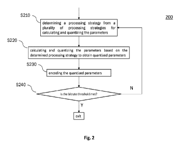
Fig. 2 is a flowchart illustrating an example of a method 200 of frame-wise
encoding
metadata for an input signal according to an embodiment of the disclosure. The
method 200
as described herein may for example be applied to the codec 100 as shown in
Fig. 1 (or any
other suitable codec). The metadata may be computed/calculated (e.g.,
extracted) from the
CA 03186884 2022-12-09
WO 2021/252811
PCT/US2021/036886
input (audio or video) signal by using a suitable codec (coder/decoder).
Generally speaking,
the metadata may be used to help regeneration of the input signal at the
decoder side. The
metadata may comprise a plurality of at least partially interrelated
parameters that are
calculable from the input signal. That is to say, at least some of the
parameters of the input
signal may be calculated (e.g., generated or regenerated) in dependence on at
least some of
the other parameters, such that, depending on various circumstances, not all
of the parameters
have to be always transmitted in plain.
The method 200 may be iteratively performed, e.g., by using a looping process
(which
will be described in detail below) for each frame of the input signal. In
particular, the method
200 (or more precisely, the looping process) starts with step S210 by
determining a
processing strategy from a plurality of processing strategies for calculating
and quantizing the
parameters.
Once the processing strategy has been determined (e.g., selected) in step
S210, the
looping process proceeds to step S220 of calculating and quantizing the
parameters based on
the determined processing strategy to obtain quantized parameters.
Subsequently in step S230, the (quantized) parameters are encoded accordingly,
and
then a (resulting) bitrate is estimated (e.g., calculated) from the encoded
parameters and a
decision is being made based on the estimated bitrate together with at least
one target bitrate
threshold (e.g., predefined or preconfigured) in step S240.
If the bitrate threshold is met, e.g., the estimated bitrate is equal to or
less than the
bitrate threshold, the method 200 exits the processing loop. Otherwise, the
loop returns back
to step S210 and continue with the steps S210 to S240. Particularly, when re-
entering the
loop, a new processing strategy may be determined, in order to meet the
bitrate threshold
target.
As can be understood and appreciated by the skilled person, the plurality of
processing strategies for calculating and quantizing the parameters may be
provided in any
suitable manner, such as, predefined or preconfigured. Accordingly, the
processing strategy
may also be determined, from the plurality of processing strategies, in any
suitable manner.
For instance, depending on a (current) bitrate requirement, a suitable
processing strategy may
be selected out of the plurality of processing strategies, such that a
resulting bitrate after
performing the calculation, quantization and encoding (e.g., with or without
entropy coding)
based on the so selected processing strategy meets the (current) bitrate
requirement.
Since the looping process is generally directed to (among others) the
processing
relating to quantization, in some cases, the looping process may also be
referred to as a
21
CA 03186884 2022-12-09
WO 2021/252811
PCT/US2021/036886
quantization loop (or simply loop for short). In a similar manner, since the
processing
strategy is also generally directed to (among others) the processing relating
to quantization, in
some cases, the processing strategy may also be referred to as a quantization
strategy (or, in
some other cases, interchangeably as a quantization scheme). Further, it is to
be noted that the
encoding process may use any suitable coding procedure including but is not
limited to,
entropy coding or coding without entropy (e.g., base2 coding). Of course, any
other suitable
coding mechanism may be adopted depending on various implementations and/or
requirements.
Specifically, each one of the plurality of processing strategies may comprise
a
respective first indication that is indicative of an ordering (or a sequence)
related to the
calculation and quantization of individual parameters. That is to say, the
first indication may
comprise sequence information indicating when and in which order the
individual parameters
are calculated and quantized. As an example (but not as limitation), the first
indication may
comprise information indicating that all the parameters are calculated first
before any of them
are being quantized.
Now the looping process will be described in more detail with reference to the
examples as shown in Figs. 3 and 4.
As indicated above, in codecs with short strides or frame updates, the
parameters may
be oversampled if they are all included in every frame. Thus, the primary
focus of the present
disclosure is to propose mechanisms to minimize side information as much as
possible, but
yet to retain a short frame update rate for the audio essence and parameters.
To address the above issue, particularly to assess the expansion of side
information,
broadly speaking, the inventor of the present disclosure generally proposes a
mechanism of
incorporating time-differential estimates for parameters of some (frequency)
bands along
with non-differential estimates for parameters of other (frequency) bands. The
proposed
approach interleaves which bands are time-differentially encoded and non-
differentially
encoded so that every band is regularly refreshed with a non-differential
calculation without
the need of a full parameter update. The core concept is that as the frame
size decreases, then
the frame to frame correlation of parameters increases and thus increased
coding gains can be
made by time-differentially encoding parameters.
In addition to the frequency interleaving of time-differential coding, it is
also
introduced with the concept of an iterative and stepwise approach to selecting
an optimal
parameter quantization scheme that searches for a 'best' (or optimal)
quantization scheme
from multiple alternatives. In this case, the term 'best' or 'optimal' may not
necessarily be
22
CA 03186884 2022-12-09
WO 2021/252811
PCT/US2021/036886
the quantization scheme with the lowest parameter bit rate, but one which
mitigates state for
the decoder.
For example, the use of time-differential encoding may generally have the
downside
primarily in the fact that there is frame to frame state introduced which can
present problems
when, during transmission, the audio stream might undergo packet loss. In this
case, both
audio and parameters may be lost and any parameters which are being updated
with time-
differential coding may experience multiple subsequent frames of potential
artefacts. In the
present disclosure, the decoder mitigations of said issue are generally not
addressed. Instead,
the issue is generally addressed (mitigated) by choosing an appropriate
quantization scheme
which would limit this behavior as much as possible. Broadly speaking, the
encode (encoder
side) mitigation generally involves an iterative selection process for the
quantization and
entropy encoding which attempts to minimize the extent to which artefacts
arising from
packet loss may be introduced due to the use of time-differential coding.
Now referring back to the figures, Fig. 3 is a flowchart schematically
illustrating an
example of a processing loop 300 according to an embodiment of the disclosure.
The processing loop 300 starts with step S310 where a first bitrate
(hereinafter
referred to as bl) is calculated (or estimated). In some possible
implementations, for every
frame, the entropy of the non-differentially and/or frequency-differentially
quantized
parameters is estimated. In some other possible implementations, the first
bitrate bl may be
calculated as the minimum of non-differential and frequency-differential
coding schemes
coded with (trained) entropy coders (e.g., Huffman or Arithmetic coding).
In step S320, the first bitrate bl is compared with a target bitrate
(hereinafter referred
to as t). If the parameter bit rate estimate bl is within (equal to or less
than) the target bitrate
t, then the processing loop exits. As a result, the parameters are encoded so
that any extra
available bits are supplied to the audio encoder to increase the bit rate of
the audio essence.
If step S320 fails (i.e., the estimated bitrate bl is larger than the target
bitrate t), then
in step S330 a second bit rate (hereinafter referred to as b2) of the
quantized parameters is
calculated. In some possible implementations, the second bitrate b2 may be
calculated in a
non-differential manner without entropy coding (e.g., by using base2 coding).
Then in step S340, the second bitrate b2 is compared with the target bitrate
t. If the
second bitrate b2 is within (equal to or less than) the target bitrate t, the
processing loop exits.
Otherwise, a third bit rate (hereinafter referred to as b3) of the parameters
is
calculated in step S350. In some possible implementations, the third bitrate
b3 may be
calculated by time-differential coding with the (trained) entropy coders. In
some further
23
CA 03186884 2022-12-09
WO 2021/252811
PCT/US2021/036886
possible implementations, a subset of parameter values in the current frame
may be quantized
and then subtracted from the quantized parameter values in the previous frame,
and the
differential quantized parameter value and entropy may be calculated.
In step S360, if the calculated bitrate b3 is equal to or below the threshold
t, then the
processing loop exits, and the parameters are encoded with the supplied
bitrate and the extra
bits are supplied to encode the audio with.
Otherwise, various measures may be implemented in step S370 in order to
eventually
meet the target bitrate threshold t.
For example, in some possible implementations, a second, coarser processing
strategy
(quantization strategy) may be selected from the plurality of processing
strategies. In such
cases, as will be understood and appreciated by the skilled person, the
quantization process
may include several levels of increasingly coarse quantization such as, for
example, fine,
moderate, coarse and extra coarse quantization strategies. Then, after
determining (e.g.,
selecting) the coarser quantization strategy, the processing loop repeats the
steps of S310 to
S360.
In some other possible implementations, a step of reducing the number of
frequency
bands may be performed in S370. Then the steps (i.e., steps S310 to S360)
mentioned above
may be repeated with the reduced band configuration. This would generally
reduce the total
number of parameters to quantize and can often result in a low bit rate for
(at least) some
frames.
Alternatively or additionally, in yet some further implementations, it may
also be
possible to perform a step of freezing (i.e., reusing) the parameters in a
band from the
previous frame. This would basically stop a parameter from changing with time,
thereby
resulting in reduced entropy for time-differential entropy coding. For
example, as displayed
in Table 2 (which will be described in detail below), when encoding with
coding scheme 4a,
then one may freeze parameters in frequency bands 2, 6, and 10. This would
typically result
is reduced entropy, no change to the decoder or to the entropy coding scheme,
and a slight
impact to quality. It is to be noted that the above example of 2, 6 and 10 is
just an illustrative
example, and one can have many band configurations that can be frozen across
multiple
frames, as will be understood and appreciated by the skilled person. For
instance, if one is
freezing all frequency bands over a period of 2 frames, then the encoder can
send half of the
bands in frame N and the remaining half in frame N+1 (thereby reducing the
total number of
parameters to be sent), which generally means that the decoder will get all
(e.g., 12) updated
frequency bands every other frame. In such cases, if one frame is lost, there
is generally the
24
CA 03186884 2022-12-09
WO 2021/252811
PCT/US2021/036886
option of extrapolating from the last two good frames. When recovering from
packet loss, it
is possible to interpolate between the bands that were received with a given
frame.
Notably, if the loop exits at step x, then the final parameter bitrate is the
bitrate that is
computed at that step x.
Furthermore, in some implementations, it may be possible (or even desirable)
to
consider designing the bitrate b3 with the coarsest quantization strategy
(among the given
plurality of quantization strategies available to quantize the parameters) as
guaranteed to be
less than the target bitrate threshold t. In such cases, it may be guaranteed
that there always
exists a solution for fitting parameter bitrate within the target bitrate t.
Fig. 4 is a flowchart schematically illustrating an example of a processing
loop 400
according to another embodiment of the disclosure. Particularly, identical or
like reference
numbers in the loop 400 of Fig. 4 generally indicate identical or like
elements in the loop 300
as shown in Fig. 3, such that repeated description thereof may be omitted for
reasons of
conciseness.
In particular, the processing loop of Fig. 4 may be specifically suitable for
cases
where two bitrate thresholds (represented as a target bitrate threshold ti and
a maximum
bitrate threshold t2) are used, as opposed to the single target bitrate
threshold scenario as
shown in Fig. 3. Broadly speaking, the target bitrate threshold t or ti may be
considered as a
target or goal that is good to achieve, whilst the maximum bitrate threshold
t2 may be simply
seen as the 'hard' threshold that should not exceed.
More particularly, the steps S410 to S470 are the same as those (i.e., steps
S310 to
S370) in Fig. 3, such that repeated description thereof may be omitted for
reasons of
conciseness.
However, instead of directly switching to step S470 if the condition of S460
fails to
be met, an additional step S461 is inserted by computing a fourth bitrate (b4)
as the minimum
of the bitrate bl, b2 and b3. Then the fourth bitrate b4 is compared with the
maximum bitrate
threshold t2 in step S462.
If the fourth bitrate b4 is equal to or less than the maximum bitrate
threshold t2, the
processing loop 400 exits; otherwise, the processing loop 400 continues with
step S470
(which is essentially the same as step S370 in Fig. 4) and repeat the steps of
S410 to S462.
Similar as Fig. 3, if the loop exits at step x, then the final parameter
bitrate is the
bitrate that is computed at that step x.
Moreover, in some implementations, it may also be possible (or even desirable)
to
consider designing the bitrate b3 with the coarsest quantization strategy
(among the given
CA 03186884 2022-12-09
WO 2021/252811
PCT/US2021/036886
plurality of quantization strategies available to quantize the parameters) as
guaranteed to be
less than the maximum bitrate threshold t2. In such cases, it may be
guaranteed that there
always exists a solution for fitting parameter bitrate within the maximum
bitrate t2.
Summarizing, steps S310, S330 and S350 of Fig. 3 and correspondingly also
steps
S410, S430 and S450 of Fig. 4 generally have no impact on the audio quality.
Step S461 of
Fig. 4 would however reduce quality by having an impact on both the audio bit
rate and
parameter bit rate. Further, any of the possible techniques/mentioned above in
step S370 of
Fig. 3 and S470 of Fig. 4 (e.g., moving to coarser quantization, band
reduction by reducing
frequency resolution, band reduction by reducing time resolution, etc.) would
basically have
a negative impact on quality. Thus, the steps in the examples of Figs. 3 and 4
are ordered in
such a way as to minimize quality degradations or to address constraints in
other areas.
Broadly speaking, the method as described in the present disclosure tends to
choose one or
more of the above illustrated techniques to keep the balance between metadata
bitrate
reduction and perceptual quality.
There are also additional considerations that go into the specific ordering of
the above
steps and the reason for possibly two target parameter bit rates (i.e., ti and
t2).
In particular, the stepwise ordering allows one to terminate the procedure if
the
constraints are met. This would generally reduce computational load when
calculations are
done serially, because one will typically not proceed through all available
steps.
Further, the ordering also allows an implicit preference of alternatives. For
example,
ordering the non-differential entropy coding as the first step would generally
mean that this
alternative is preferred if it meets the constraints. This is an encoder
mitigation to minimize
state to improve quality during conditions of packet loss.
Moreover, the possibility of using two targets (t1 and t2) would generally
allow the
ability to trade off audio bit rate and parameter bit rate with greater
control.
Now, description of interleaving to achieve time-differential coding will be
described
in more detail.
Some possible implementations to manage interleaving of time-differential
entropy
coding is displayed in Table 2.
26
CA 03186884 2022-12-09
WO 2021/252811
PCT/US2021/036886
Coding Scheme Time Diff Coding, Bands 1-12
base 0 0 0 0 0 0 0 0 0 0 0 0
4a 0 1 1 1 0 1 1 1 0 1 1 1
4b 1 0 1 1 1 0 1 1 1 0 1 1
4c 1 1 0 1 1 1 0 1 1 1 0 1
4d 1 1 1 0 1 1 1 0 1 1 1 0
Table 2. Interleaved time-differential coding schemes
In this specific example, it is generally proposed 5 configurations for
metadata
bitstream coding, each of them consisting of 12 (frequency) bands. More
particularly, the
band specified by 0 is coded non-differentially and the band specified by 1 is
coded time-
differentially (i.e., quantize the parameter and subtract from the quantized
parameter in the
previous frame).
As described in the example, the parameter bit rate of each frame is first
evaluated by
coding non-differentially (i.e., base) by quantizing the parameters (for
example see step S410
or S510). Then, at step S450 or S550, the time-differential coding scheme is
chosen (if so
required) based on the previous frame's coding scheme.
An example of mapping from previous frame's coding scheme to current frame's
time-differential coding scheme is shown below in Table 3:
previous frame's current frame's time-
coding scheme differential coding scheme
base 4a
4a 4b
4b 4c
4c 4d
4d 4a
Table 3. Mapping of the time-differential coding schemes
27
CA 03186884 2022-12-09
WO 2021/252811
PCT/US2021/036886
Notably, in the present example, the term "base" used in Table 3 generally
refers to
the non-differential coding scheme. Thus, as can be seen from Table 3, the
time-differential
coding always cycles through 4a to 4d (and back again). It is possible to
continue cycling
without ever requiring non-differential coding to be implemented. And in this
particular
example, the maximum memory or 'state' of the codec is the current frame and
three past
frames (i.e., in total four frames). Of course, as will be understood and
appreciated by the
skilled person, the numbers of 5 configurations and 12 (frequency) bands etc.
are merely used
as examples for illustrative purpose, any other suitable number may be used,
depending on
various implementations and/or requirements. Analogous or similar arguments
apply to the
switching between coding schemes as shown in Table 3, which may likewise adopt
any
suitable technique.
Notably, if a different quantization scheme is chosen, then the indices from
previous
frame quantized with a different quantization scheme may be first mapped to
that of the
current frame. Generally speaking, the step of mapping may be required to
allow time-
differential coding of parameters e.g., when the number of quantization levels
changes from
one frame to the next, thereby allowing time-differential coding between
frames without
resorting to having to send a non-differential frame each time the
quantization scheme is
changed.
As a possible example, the mapping of the indices may be performed based on
the
formulae:
indexcvr = round(indexp,v x (quant_IvIcur ¨ 1)1(quant_IvIpr, ¨ 1)) (13)
where index, denotes the indices of the current frame after mapping, indexpr,
denotes
the indices of the previous frame, quant_IvIcur denotes the quantization level
of the current
frame and quant_IvIprev denotes the quantization level of the previous frame.
As a simple illustrative example, let the quantization range be 0 to 2, and
let the
previous quantization levels be 11. In the case of uniform quantization, this
would generally
mean that each quantization step would be 0.2. Further, let the current
quantization levels be
21, which means that each quantization step is 0.1 with uniform quantization.
Based on these
assumptions, if a quantized value in the previous frame was 0.4, then with 11
uniform
quantization levels, one would get the following previous index indexprev = 2.
The mapping
provides the quantized indices of the previous frame's metadata as if it were
quantized using
the current frame's quantization levels. Thus, in this example, if the
quantization levels in the
current frame are 21, then the quantized value 0.4 would be mapped to index,r
= 4. Once
28
CA 03186884 2022-12-09
WO 2021/252811
PCT/US2021/036886
mapped indices are computed, the difference between the current frame and
previous frame
indices is calculated, and this difference is encoded. Analogous or similar
approaches may
also be applied to the frequency-differential coding, if needs be, as will be
understood and
appreciated by the skilled person.
Of course, any other suitable mapping schemes (e.g., by using a lookup table
or
similar) may be adopted, depending on various implementations and/or
requirements.
Moreover, as indicated above, a single metadata parameter may be quantized
from a
continuous numerical value to an index representing a discrete value. In non-
differential
coding, the information that is coded for that metadata parameter corresponds
directly to that
index. In time-differential coding, the information that is coded is the
difference between the
index of that metadata parameter from the current frame, and the index of the
same metadata
parameter from the previous frame. As will be understood and appreciated by
the skilled
person, the above illustrated general concept of time-differential coding may
be further
extended, e.g., to a plurality of frequency bands. Accordingly, the metadata
parameter may be
extended similarly, e.g., to a plurality of parameters respectively
corresponding to the
plurality of frequency bands, as appropriate. Frequency-differential coding
follows a similar
principle, but the coded difference is between one frequency band's metadata
of the current
frame and the other frequency band's metadata of the current frame (as opposed
to the
current frame minus the previous frame in time-differential coding). As a
simple example
(but not as limitation), assuming a0, al, a2 and a3 denote parameters indices
in 4 frequency
bands of a particular frame, then, in one example implementation, the
frequency-differential
indices can be a0, a0-al, al-a2, a2-a3. As will be appreciated by the skilled
person, the
general idea behind the (time- and/or frequency-) differential coding is that
metadata may
typically change slowly from frame to frame, or from frequency-band to
frequency-band, so
that even if the original value of the metadata was large, the difference
between it and the
previous frame's metadata, or difference between it and other frequency band's
metadata,
would likely be small. This is advantageous because, generally, parameters
with statistical
distributions that tend towards zero can be coded using fewer bits. Thus, even
if some of the
example implementations might make reference briefly or merely to time-
differential coding,
the skilled person would appreciate that also frequency-differential coding
may be applied
thereto (possibly with minor suitable adaption).
Some further possible examples of the present disclosure may relate to a
process of
processing an input audio signal, represented in sub-bands to produce a down-
mixed signal
and associated metadata can be performed by one or more processors. The
process can
29
CA 03186884 2022-12-09
WO 2021/252811
PCT/US2021/036886
include, for each sub-band, determining a down-mix matrix and associated
metadata; and
remixing each of said sub-bands according to said down-mix matrix to produce
said down-
mixed signal. One or more quantization strategies and one or more coding
strategies can be
used to encode the metadata given a target and/or maximum metadata bitrate
limitation.
In some implementations, the process can include non-differential entropy
coding of
all sub-bands. The process can further include frequency-differential entropy
coding of all
sub-bands. The process can further include combining frequency interleaving
with time-
differential encoding of quantized parameters corresponding to selected
subbands for a low
latency audio codec as described in detail above.
The process can further include non-entropy coding of sub-band metadata.
Iterating
through steps to find an appropriate coding strategy to meet bitrate and audio
quality
requirements, and to reduce decoder state. The process can further include
reducing
frequency resolution by reducing the number of subbands in which spatial
metadata is to be
coded, e.g., 12 bands to 6 bands. The process can include reducing time
resolution by time-
fixing (or freezing) one or more sub-band metadata, such that a sub-band's
metadata need not
be sent. The process can include using of multiple quantization strategies
where each strategy
is a combination of quantization levels for various spatial metadata
parameters, the process
can further include choosing between these quantization strategies to ensure
that the bitrate
targets are met. The process can include iterating through steps to find an
appropriate
quantization scheme to meet bitrate and audio quality requirements. The
iteration method
focusing on getting desired metadata bitrate with desired quantization scheme,
minimal
computational complexity, and reduced decoder state. If the desired
quantization level does
not fit in the desired bitrate range, then falling back to a (e.g., coarser)
quantization scheme
by ensuring minimal impact on audio quality.
In some implementations, a mapping of indexes from previous frames quantized
to a
different number of levels to that of the current frame, allows time-
differential coding
between frames without resorting to having to send a non-differential frame
each time a
different quantization level is needed.
In various implementations, the quantization (conversion of continuous values
to
discrete indices for encoding) can include determining the best value for the
coefficients
according to the current needs, by manipulating the order of calculation and
quantization of
successive metadata coefficients.
A computing device implementing the techniques described above can have the
following example architecture. Other architectures are possible, including
architectures with
CA 03186884 2022-12-09
WO 2021/252811
PCT/US2021/036886
more or fewer components. In some implementations, the example architecture
includes one
or more processors (e.g., dual-core Intel Xeon Processors), one or more
output devices
(e.g., LCD), one or more network interfaces, one or more input devices (e.g.,
mouse,
keyboard, touch-sensitive display) and one or more computer-readable mediums
(e.g., RAM,
ROM, SDRAM, hard disk, optical disk, flash memory, etc.). These components can
exchange
communications and data over one or more communication channels (e.g., buses),
which can
utilize various hardware and software for facilitating the transfer of data
and control signals
between components.
The term "computer-readable medium" refers to a medium that participates in
providing instructions to processor for execution, including without
limitation, non-volatile
media (e.g., optical or magnetic disks), volatile media (e.g., memory) and
transmission
media. Transmission media includes, without limitation, coaxial cables, copper
wire and fiber
optics.
Computer-readable medium can further include operating system (e.g., a Linux
operating system), network communication module, audio interface manager,
audio
processing manager and live content distributor. Operating system can be multi-
user,
multiprocessing, multitasking, multithreading, real time, etc. Operating
system performs
basic tasks, including but not limited to: recognizing input from and
providing output to
network interfaces 706 and/or devices 708; keeping track and managing files
and directories
on computer-readable mediums (e.g., memory or a storage device); controlling
peripheral
devices; and managing traffic on the one or more communication channels.
Network
communications module includes various components for establishing and
maintaining
network connections (e.g., software for implementing communication protocols,
such as
TCP/IP, HTTP, etc.).
Architecture can be implemented in a parallel processing or peer-to-peer
infrastructure or on a single device with one or more processors. Software can
include
multiple software components or can be a single body of code.
The described features can be implemented advantageously in one or more
computer
programs that are executable on a programmable system including at least one
programmable
processor coupled to receive data and instructions from, and to transmit data
and instructions
to, a data storage system, at least one input device, and at least one output
device. A computer
program is a set of instructions that can be used, directly or indirectly, in
a computer to
perform a certain activity or bring about a certain result. A computer program
can be written
in any form of programming language (e.g., Objective-C, Java), including
compiled or
31
CA 03186884 2022-12-09
WO 2021/252811
PCT/US2021/036886
interpreted languages, and it can be deployed in any form, including as a
stand-alone program
or as a module, component, subroutine, a browser-based web application, or
other unit
suitable for use in a computing environment.
Suitable processors for the execution of a program of instructions include, by
way of
example, both general and special purpose microprocessors, and the sole
processor or one of
multiple processors or cores, of any kind of computer. Generally, a processor
will receive
instructions and data from a read-only memory or a random access memory or
both. The
essential elements of a computer are a processor for executing instructions
and one or more
memories for storing instructions and data. Generally, a computer will also
include, or be
operatively coupled to communicate with, one or more mass storage devices for
storing data
files; such devices include magnetic disks, such as internal hard disks and
removable disks;
magneto-optical disks; and optical disks. Storage devices suitable for
tangibly embodying
computer program instructions and data include all forms of non-volatile
memory, including
by way of example semiconductor memory devices, such as EPROM, EEPROM, and
flash
memory devices; magnetic disks such as internal hard disks and removable
disks; magneto-
optical disks; and CD-ROM and DVD-ROM disks. The processor and the memory can
be
supplemented by, or incorporated in, ASICs (application-specific integrated
circuits).
To provide for interaction with a user, the features can be implemented on a
computer
having a display device such as a CRT (cathode ray tube) or LCD (liquid
crystal display)
monitor or a retina display device for displaying information to the user. The
computer can
have a touch surface input device (e.g., a touch screen) or a keyboard and a
pointing device
such as a mouse or a trackball by which the user can provide input to the
computer. The
computer can have a voice input device for receiving voice commands from the
user.
The features can be implemented in a computer system that includes a back-end
component, such as a data server, or that includes a middleware component,
such as an
application server or an Internet server, or that includes a front-end
component, such as a
client computer having a graphical user interface or an Internet browser, or
any combination
of them. The components of the system can be connected by any form or medium
of digital
data communication such as a communication network. Examples of communication
networks include, e.g., a LAN, a WAN, and the computers and networks forming
the
Internet.
The computing system can include clients and servers. A client and server are
generally remote from each other and typically interact through a
communication network.
The relationship of client and server arises by virtue of computer programs
running on the
32
CA 03186884 2022-12-09
WO 2021/252811
PCT/US2021/036886
respective computers and having a client-server relationship to each other. In
some
embodiments, a server transmits data (e.g., an HTML page) to a client device
(e.g., for
purposes of displaying data to and receiving user input from a user
interacting with the client
device). Data generated at the client device (e.g., a result of the user
interaction) can be
received from the client device at the server.
A system of one or more computers can be configured to perform particular
actions
by virtue of having software, firmware, hardware, or a combination of them
installed on the
system that in operation causes or cause the system to perform the actions.
One or more
computer programs can be configured to perform particular actions by virtue of
including
instructions that, when executed by data processing apparatus, cause the
apparatus to perform
the actions.
While this specification contains many specific implementation details, these
should
not be construed as limitations on the scope of any inventions or of what may
be claimed, but
rather as descriptions of features specific to particular embodiments of
particular inventions.
Certain features that are described in this specification in the context of
separate
embodiments can also be implemented in combination in a single embodiment.
Conversely,
various features that are described in the context of a single embodiment can
also be
implemented in multiple embodiments separately or in any suitable
subcombination.
Moreover, although features may be described above as acting in certain
combinations and
even initially claimed as such, one or more features from a claimed
combination can in some
cases be excised from the combination, and the claimed combination may be
directed to a
subcombination or variation of a subcombination.
Similarly, while operations are depicted in the drawings in a particular
order, this
should not be understood as requiring that such operations be performed in the
particular
order shown or in sequential order, or that all illustrated operations be
performed, to achieve
desirable results. In certain circumstances, multitasking and parallel
processing may be
advantageous. Moreover, the separation of various system components in the
embodiments
described above should not be understood as requiring such separation in all
embodiments,
and it should be understood that the described program components and systems
can
.. generally be integrated together in a single software product or packaged
into multiple
software products.
Unless specifically stated otherwise, as apparent from the following
discussions, it is
appreciated that throughout the disclosure discussions utilizing terms such as
"processing",
"computing", "calculating", "determining", "analyzing" or the like, refer to
the action and/or
33
CA 03186884 2022-12-09
WO 2021/252811
PCT/US2021/036886
processes of a computer or computing system, or similar electronic computing
devices, that
manipulate and/or transform data represented as physical, such as electronic,
quantities into
other data similarly represented as physical quantities.
Reference throughout this disclosure to "one example embodiment", "some
example
embodiments" or "an example embodiment" means that a particular feature,
structure or
characteristic described in connection with the example embodiment is included
in at least
one example embodiment of the present disclosure. Thus, appearances of the
phrases "in one
example embodiment", "in some example embodiments" or "in an example
embodiment" in
various places throughout this disclosure are not necessarily all referring to
the same example
embodiment. Furthermore, the particular features, structures or
characteristics may be
combined in any suitable manner, as would be apparent to one of ordinary skill
in the art
from this disclosure, in one or more example embodiments.
As used herein, unless otherwise specified the use of the ordinal adjectives
"first",
"second", "third", etc., to describe a common object, merely indicate that
different instances
of like objects are being referred to and are not intended to imply that the
objects so described
must be in a given sequence, either temporally, spatially, in ranking, or in
any other manner.
In the claims below and the description herein, any one of the terms
comprising,
comprised of or which comprises is an open term that means including at least
the
elements/features that follow, but not excluding others. Thus, the term
comprising, when used
in the claims, should not be interpreted as being limitative to the means or
elements or steps
listed thereafter. For example, the scope of the expression a device
comprising A and B
should not be limited to devices consisting only of elements A and B. Any one
of the terms
including or which includes or that includes as used herein is also an open
term that also
means including at least the elements/features that follow the term, but not
excluding others.
Thus, including is synonymous with and means comprising.
It should be appreciated that in the above description of example embodiments
of the
disclosure, various features of the disclosure are sometimes grouped together
in a single
example embodiment, Fig., or description thereof for the purpose of
streamlining the
disclosure and aiding in the understanding of one or more of the various
inventive aspects.
This method of disclosure, however, is not to be interpreted as reflecting an
intention that the
claims require more features than are expressly recited in each claim. Rather,
as the following
claims reflect, inventive aspects lie in less than all features of a single
foregoing disclosed
example embodiment. Thus, the claims following the Description are hereby
expressly
incorporated into this Description, with each claim standing on its own as a
separate example
34
CA 03186884 2022-12-09
WO 2021/252811
PCT/US2021/036886
embodiment of this disclosure.
Furthermore, while some example embodiments described herein include some but
not other features included in other example embodiments, combinations of
features of
different example embodiments are meant to be within the scope of the
disclosure, and form
different example embodiments, as would be understood by those skilled in the
art. For
example, in the following claims, any of the claimed example embodiments can
be used in
any combination.
In the description provided herein, numerous specific details are set forth.
However, it
is understood that example embodiments of the disclosure may be practiced
without these
specific details. In other instances, well-known methods, structures and
techniques have not
been shown in detail in order not to obscure an understanding of this
description.
Thus, while there has been described what are believed to be the best modes of
the
disclosure, those skilled in the art will recognize that other and further
modifications may be
made thereto without departing from the spirit of the disclosure, and it is
intended to claim all
such changes and modifications as fall within the scope of the disclosure. For
example, any
formulas given above are merely representative of procedures that may be used.
Functionality
may be added or deleted from the block diagrams and operations may be
interchanged among
functional blocks. Steps may be added or deleted to methods described within
the scope of
the present disclosure.
Various aspects and implementations of the present disclosure may also be
appreciated from the following enumerated example embodiments (EEEs), which
are not
claims.
EEE 1. A method of processing an input audio signal, represented in sub-bands
to
produce a down-mixed signal and associated metadata, the method including:
for each sub-band, determining a down-mix matrix and associated metadata; and;
remixing each of said sub-bands according to said down-mix matrix to produce
said
down-mixed signal.
EEE 2. The method of EEE 1 wherein the metadata is encoded using one or more
quantization strategies and one or more coding strategies given a target
and/or maximum
metadata bitrate limitation.
EEE 3. The method of EEE 2, comprising non-time-differential entropy coding of
all
sub-bands.
CA 03186884 2022-12-09
WO 2021/252811
PCT/US2021/036886
EEE 4. The method of EEE 3, comprising combining frequency interleaving with
time-differential encoding of quantized parameters corresponding to selected
subbands for a
low latency audio codec.
EEE5. The method of EEE 4, comprising non-entropy coding of sub-band metadata.
EEE 6. The method of EEE 5, wherein iterating through step 3) to 5) to find an
appropriate coding strategy to meet bitrate and audio quality requirements,
and to reduce
decoder state.
EEE 7. The method of EEE 6, comprising reducing the number of bands sent by
combination of metadata in subbands.
EEE 8. The method of EEE 7, comprising: time-fixing one or more sub-band
metadata, such that a sub-band's metadata need not be sent.
EEE 9. The method of EEE 8, comprising: using multiple quantization levels for
the
given metadata to ensure that the bitrate targets are met.
EEE 10. The method of EEE 9, wherein iterating through the steps of EEEs 3 to
9 to
.. find an appropriate quantization scheme to meet bitrate and audio quality
requirements.
EEE 11. The method of EEE 3 or EEE 9, wherein a mapping of indexes from
previous frames quantized to a different number of levels to that of the
current frame, allows
time-differential coding between frames without resorting to having to send a
non-time-
differential frame each time a different quantization level is needed.
EEE 12. The method of any of the EEEs above where the quantization includes
determining the best value for the coefficients according to the current
needs, by
manipulating the order of calculation and quantization of successive metadata
coefficients.
EEE 13. A system comprising:
one or more processors; and
a non-transitory computer-readable medium storing instructions that, when
executed
by the one or more processors, cause the one or more processors to perform
operations of any
of EEEs 1-12.
36
CA 03186884 2022-12-09
WO 2021/252811
PCT/US2021/036886
EEE 14. A non-transitory computer-readable medium storing instructions that,
when
executed by one or more processors, cause the one or more processors to
perform operations
of any of EEEs 1-12.
37