Note: Descriptions are shown in the official language in which they were submitted.
CA 03187067 2022-12-14
WO 2021/257514 PCT/US2021/037346
ULTRA-LOW INTERFACIAL TENSION SUPPORT MEDIUM FOR HIGH PRECISION
SILICONE 3D PRINTING
CROSS REFERENCE TO RELATED APPLICATIONS
[0001] This application claims the benefit of U.S. Provisional Application No.
63/039,209, filed on
June 15, 2020, which is incorporated herein by reference in its entirety.
BACKGROUND
[0002] Additive manufacturing has allowed the fabrication shapes and
structures of plastics,
metals and even ceramics that would not otherwise be possible using
conventional fabrication
techniques. Recent advancements in this field include advanced tissue
engineering, bioprinting,
and microfluidic device fabrication. One of the biggest limitations of this
method is that only
materials that solidify or cure upon extrusion can be used. Additionally,
sacrificial support is often
required when printing structures or where parts of structures being printed
are not supported by
the preceding layer. Printing into a jammed microgel system has overcome
certain problems
related to material limitations and the requirement for sacrificial support
structures.
[0003] Silicone is a widely used material due to its high thermal stability
and resistance to
weathering, ozone, moisture, and UV radiation. Its market worth is estimated
to grow to $19.34
billion by 2025. Fabrication of silicone structures can be performed using
conventional techniques
such as, for example, molding and casting or using more advanced techniques
like soft-
lithography and 3D printing. However, using conventional 3D printing
techniques to produce
silicone structures generally results in low-quality products because of the
challenges of printing
pre-polymerized silicone elastomer in its liquid state. Traditional approaches
require the ink to
solidify or "cure" once deposited from the nozzle. Recently, a novel 3D
fabrication technique was
developed in which jammed microgel systems were used as a support medium for
printing soft
materials, including silicone elastomer. The jammed microgels have unique
rheological behaviors
that enable them to be used as printing support media, including fluidizing
under large applied
stresses and behaving like solids when applied stresses are below the
material's yield stress.
These properties allow microgels to yield and flow around translating printing
needles while
trapping the "ink" deposited in space, thereby negating the effect of gravity
or buoyancy.
[0004] The fundamentals of jammed microgel rheology have been thoroughly
studied and are
fairly well understood. However, interfacial phenomena between jammed
microgels and
1
CA 03187067 2022-12-14
WO 2021/257514 PCT/US2021/037346
surrounding fluids are less well understood. These interfacial forces play a
major role in 3D
printing applications using jammed microgels since the interfacial tension
between the ink and
the support medium can lead to the disintegration of the printed structures
overtime. To minimize
the effects of interfacial tension while leveraging the stability provided by
jammed support
material, the support material must be chemically similar to the printed ink.
Hence, to overcome
limitations related to the stability of silicone structures during fabrication
processes, support
materials that are chemically similar to poly(dimethyl siloxane) (PDMS) should
be developed.
Furthermore, failure to overcome destabilizing interfacial forces will
continue to limit the printable
resolution of silicone printing, making it impossible to fabricate structures
having intricate details.
These fabricated structures would, ideally, have applications in personalized
implants, lab-on-a-
chip devices, tissue/organ-on-a-chip devices, point-of-care devices,
biological machines, and
other medical applications.
[0005] Despite advances in 3D printing of soft material, there is still a
scarcity of inks and support
materials that allow for the fabrication of 3D printed structures having low
surface roughness and
intricate details that persist over a long period of time. These needs and
other needs are satisfied
by the present disclosure.
SUM MARY
[0006] In accordance with the purpose(s) of the present disclosure, as
embodied and broadly
described herein, the disclosure, in one aspect, relates to a support material
for 3D printing of soft
materials having feature sizes <5 pm that persist over time, methods of 3D
printing using the
same, and articles that include soft matter constructed using the disclosed
methods. In one
aspect, the support materials can be jammed inverse emulsions having silicone
oils as the
continuous phase and glycerol/water mixtures as the dispersed phase. In some
aspects, the
support materials also include a surfactant. In any of these aspects, the
support materials can be
optically clear.
[0007] Other systems, methods, features, and advantages of the present
disclosure will be or
become apparent to one with skill in the art upon examination of the following
drawings and
detailed description. It is intended that all such additional systems,
methods, features, and
advantages be included within this description, be within the scope of the
present disclosure, and
be protected by the accompanying claims. In addition, all optional and
preferred features and
modifications of the described embodiments are usable in all aspects of the
disclosure taught
herein. Furthermore, the individual features of the dependent claims, as well
as all optional and
2
CA 03187067 2022-12-14
WO 2021/257514 PCT/US2021/037346
preferred features and modifications of the described embodiments are
combinable and
interchangeable with one another.
BRIEF DESCRIPTION OF THE DRAWINGS
[0008] Many aspects of the present disclosure can be better understood with
reference to the
following drawings. The components in the drawings are not necessarily to
scale, emphasis
instead being placed upon clearly illustrating the principles of the present
disclosure. Moreover,
in the drawings, like reference numerals designate corresponding parts
throughout the several
views.
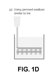
[0009] FIG. 1A shows a CAD graphic of a model scaffold to be 3D printed. FIG.
1B shows that
the conventional method of 3D printing will not be effective for printing soft
matter or liquid ink, as
the unsupported structures will sag and the final structure deviates from the
coded structure. FIG.
1C shows leveraging jammed medium for 3D printing soft matter eliminates
sagging by trapping
the ink in space, but the interfacial tension between the support medium and
the ink will cause
the printed structures to break up overtime. FIG. 1D shows that by employing a
jammed medium
similar to that of the ink, interfacial instability-related breakup of the
printed features can be
avoided, leading to indefinitely stable structures.
[0010] FIG. 2A shows a phase diagram of a typical polymer blend with an upper
critical solution
temperature (UCST). Point (i) on the phase diagram denotes a stable phase of
the two
components. Upon quenching to point (ii), the system spontaneously phase
separates into two
phases, the component B rich phase (iii), and the component A rich phase
(iii'). FIG. 2B shows
a schematic of phase separation of the polymer blend into a continuous phase
rich in component
A and a droplet phase rich in component B. However, under jamming, the size,
shape, and
distribution of the droplet phase is controlled by the yield stress of the
jammed system. FIG. 2C
shows that phase separation within a jammed system can be leveraged to be used
as a 3D
printing technique for fabricating very fine structures.
[0011] FIG. 3 shows rheological characterization of self-assembled microgels.
FIG. 3A shows
shear modulus measurements through small amplitude frequency sweeps indicate
that pure
triblock and 50:50 blend solutions exhibit solid-like behavior over long time
scales, while a pure
diblock system will behave like a viscous fluid. FIG. 3B shows unidirectional
shear rate sweep
measurements are performed to measure the yield stress of the block copolymer
systems. FIG.
3C shows thixotropic time measurements of the 50:50 blend, indicating the
recovery of solid-like
rheological properties within 1 s of removal of applied stress. FIG. 3D shows
microscopic images
3
CA 03187067 2022-12-14
WO 2021/257514 PCT/US2021/037346
taken with phase contrast illumination, illustrating the presence of microgels
on the order of 2-4
pm in diameter. These results demonstrate that the properties of microgel
systems can be
assessed using known techniques; improved properties of the present supports
based on inverse
emulsions can be seen when these types of measurements are performed
thereupon.
[0012] FIG. 4 shows a 3D printed silicone structure in self-assembled micro-
organogels. FIG. 4A
shows model trachea implants printed into jammed microgel supports using an
RTV silicone.
After curing, printed structures were removed from the support material and
handled. FIG. 4B
shows cross-sectional views of model trachea, demonstrating the ability to
print structures with
wall thicknesses of 400 pm. FIGs. 4C-40 show silicone scaffolds printed with
sinusoidal wave
patterns in the x-y and x-z directions, demonstrating the ability to print
structures with 250 pm
feature sizes. FIGs. 4E-4G show macroscopic images of a perfusable tubular
network printed
into a micro-organogel support. In one aspect, the jammed inverse emulsion
supports disclosed
herein can be used in the printing of these and other structures while
offering improvements in
feature size, surface roughness, and stability of features over time.
[0013] FIGs. 5A-5B show rheological characterization of the inverse emulsions
of varying volume
fractions and at constant droplet size of 2 pm. FIGs. 5C-50 show rheological
characterization of
the inverse emulsions of varying droplet size and at constant volume fraction
of Oaq = 0.75. For
FIGs. 5A and 5C, shear modulus measurements at small amplitude frequency
sweeps show the
inverse emulsions exhibit solid-like behavior over long time scales. The
storage modulus is
shown to increase with increase in the emulsion volume fraction and decrease
in the droplet size.
For FIGs. 5B and 50, unidirectional shear rate sweep measurements are
performed to measure
the yield stress of the inverse emulsion and the critical yield stress is seen
to increase with an
increase in the emulsion volume fraction and decrease in the droplet size.
[0014] FIG. 6 shows time-lapse measurements of neat silicone oil printed into
jammed micro-
organogel. The interfacial tension between the micro-organogel and the
silicone oil results in
instability-related breakups. The breakup time of the features depends on the
feature size and
the viscosity of the printed silicone oil. The features after breakup reduce
total interfacial energy
by reforming closer to a spherical shape. In one aspect, the jammed inverse
emulsion supports
disclosed herein allow for longer stability of microscopic features when
compared to micro-
organogel supports.
[0015] FIG. 7 shows that feature size can be predicted from flow rate (Q) and
translational velocity
(v). The printed features show ideal behavior across different flow rates and
velocities.
4
CA 03187067 2022-12-14
WO 2021/257514 PCT/US2021/037346
[0016] FIG. 8 shows (left) a structure of poly(dimethylsiloxane) (PDMS) and
(right) a structure of
poly(methylphenylsiloxane) (PMPS).
[0017] FIG. 9 shows a schematic of a spinning drop method, where a capillary
tube filled with a
bulk phase of a denser component and a drop of a lighter component is rotated
at a constant
angular velocity. The droplet radius correlates with the interfacial tension
between the two liquids
through Vonnegut's equation.
[0018] FIG. 10 shows a schematic of spherical segments with different radii of
curvature to be
printed. Print accuracy is measured as deviation of printed curvature from
coded curvature. Print
variability is measured as deviation in surface roughness of the printed
structure relative to the
coded structure.
[0019] FIGs. 11A-11C show graphical representations of the role of interfacial
tension between
ink and support matrix. FIG. 11A shows high interfacial tension; FIG. 11B
shows low interfacial
tension; and FIG. 11C shows ultra-low interfacial tension.
[0020] FIGs. 12A-12C show a silicone 3D printing of a patient's brain aneurysm
indicating
accuracy of the disclosed approach. FIG. 12A is an original model of the
aneurysm based on a
computed tomography (CT) scan; FIG. 12B shows a model printed using the
disclosed
technology; and FIG. 12C shows a 3D overlay of the two models.
[0021] FIG. 13A is a photograph of the printing process for the brain aneurysm
model of FIG.
12B. FIG. 13B is a photograph of the printing process for a model tri-leaflet
heart valve.
[0022] Additional advantages of the invention will be set forth in part in the
description which
follows, and in part will be obvious from the description, or can be learned
by practice of the
invention. The advantages of the invention will be realized and attained by
means of the elements
and combinations particularly pointed out in the appended claims. It is to be
understood that both
the foregoing general description and the following detailed description are
exemplary and
explanatory only and are not restrictive of the invention, as claimed.
DETAILED DESCRIPTION
[0023] Many modifications and other embodiments disclosed herein will come to
mind to one
skilled in the art to which the disclosed compositions and methods pertain
having the benefit of
the teachings presented in the foregoing descriptions and the associated
drawings. Therefore, it
is to be understood that the disclosures are not to be limited to the specific
embodiments disclosed
and that modifications and other embodiments are intended to be included
within the scope of the
CA 03187067 2022-12-14
WO 2021/257514 PCT/US2021/037346
appended claims. The skilled artisan will recognize many variants and
adaptations of the aspects
described herein. These variants and adaptations are intended to be included
in the teachings of
this disclosure and to be encompassed by the claims herein.
[0024] Although specific terms are employed herein, they are used in a generic
and descriptive
sense only and not for purposes of limitation.
[0025] As will be apparent to those of skill in the art upon reading this
disclosure, each of the
individual embodiments described and illustrated herein has discrete
components and features
which may be readily separated from or combined with the features of any of
the other several
embodiments without departing from the scope or spirit of the present
disclosure.
[0026] Any recited method can be carried out in the order of events recited or
in any other order
that is logically possible. That is, unless otherwise expressly stated, it is
in no way intended that
any method or aspect set forth herein be construed as requiring that its steps
be performed in a
specific order. Accordingly, where a method claim does not specifically state
in the claims or
descriptions that the steps are to be limited to a specific order, it is no
way intended that an order
be inferred, in any respect. This holds for any possible non-express basis for
interpretation,
including matters of logic with respect to arrangement of steps or operational
flow, plain meaning
derived from grammatical organization or punctuation, or the number or type of
aspects described
in the specification.
[0027] All publications mentioned herein are incorporated herein by reference
to disclose and
describe the methods and/or materials in connection with which the
publications are cited. The
publications discussed herein are provided solely for their disclosure prior
to the filing date of the
present application. Nothing herein is to be construed as an admission that
the present invention
is not entitled to antedate such publication by virtue of prior invention.
Further, the dates of
publication provided herein can be different from the actual publication
dates, which can require
independent confirmation.
[0028] While aspects of the present disclosure can be described and claimed in
a particular
statutory class, such as the system statutory class, this is for convenience
only and one of skill in
the art will understand that each aspect of the present disclosure can be
described and claimed
in any statutory class.
[0029] It is also to be understood that the terminology used herein is for the
purpose of describing
particular aspects only and is not intended to be limiting. Unless defined
otherwise, all technical
6
CA 03187067 2022-12-14
WO 2021/257514 PCT/US2021/037346
and scientific terms used herein have the same meaning as commonly understood
by one of
ordinary skill in the art to which the disclosed compositions and methods
belong. It will be further
understood that terms, such as those defined in commonly used dictionaries,
should be
interpreted as having a meaning that is consistent with their meaning in the
context of the
specification and relevant art and should not be interpreted in an idealized
or overly formal sense
unless expressly defined herein.
[0030] Prior to describing the various aspects of the present disclosure, the
following definitions
are provided and should be used unless otherwise indicated. Additional terms
may be defined
elsewhere in the present disclosure.
Definitions
[0031] As used herein, "comprising" is to be interpreted as specifying the
presence of the stated
features, integers, steps, or components as referred to, but does not preclude
the presence or
addition of one or more features, integers, steps, or components, or groups
thereof. Moreover,
each of the terms "by", "comprising," "comprises", "comprised of,"
"including," "includes,"
"included," "involving," "involves," "involved," and "such as" are used in
their open, non-limiting
sense and may be used interchangeably. Further, the term "comprising" is
intended to include
examples and aspects encompassed by the terms "consisting essentially of" and
"consisting of."
Similarly, the term "consisting essentially of" is intended to include
examples encompassed by
the term "consisting of.
[0032] As used in the specification and the appended claims, the singular
forms "a," "an" and
"the" include plural referents unless the context clearly dictates otherwise.
Thus, for example,
reference to "a silicone oil," "a surfactant," or "an ink," include, but are
not limited to, mixtures of
two or more such silicone oils, surfactants, or inks, and the like.
[0033] A "scaffold" as used herein refers to a structure useful for providing
support to inks during
3D printing. A scaffold is typically three-dimensional and includes solid
structures upon which
inks can be deposited, as well as open spaces. Scaffolds for 3D printed
tissues typically include
biocompatible materials (FIG. 1A).
[0034] "Sagging" refers to deformation of areas of 3D printed inks caused by
gravity or other
forces when the areas are unsupported by a scaffold such as, for example, when
the inks are
printed over an open space between solid structures in a scaffold (FIG. 1B).
[0035] As used herein, "jammed medium" refers to a medium, such as a microgel
or inverse
7
CA 03187067 2022-12-14
WO 2021/257514 PCT/US2021/037346
emulsion, in which inks can be 3D printed. The jammed medium provides support
for the 3D
printed structure without the need for a scaffold. In one aspect, a moving
injection nozzle can
follow any 3D path desired and can locally shear the jammed medium, leading to
temporary
fluidization at the point of injection (FIG. 2C). Further in this aspect, ink
can be deposited and the
injection nozzle then moves away from the deposition site. When the nozzle has
left, the
surrounding jammed medium rapidly moves back into place, trapping the injected
material in
space and eliminating the sagging problems that accompany use of traditional
scaffolds (FIGs.
1C-1D).
[0036] "Shear stress" is the component of stress coplanar with the cross
section of a material
and, as used herein, is primarily caused by friction among fluid particles due
to the viscosity of
the bulk fluid. Shear stress tends to cause a material to deform by slipping
along a plane parallel
to the stress (FIG. 3B).
[0037] As used herein, "shear modulus," typically represented by G, describes
a material's
response to shear stress. A material having a large shear modulus is rigid and
a large force is
required to deform the material, while a material with a smaller shear modulus
is easier to deform
(FIG. 3A).
[0038] When one layer of a material passes over an adjacent layer, the rate of
change of the
velocity at which this occurs is referred to as "shear rate." In one aspect,
shear rate is the rate at
which a progressive shearing deformation is applied to the material (FIG. 3C).
[0039] "Yield stress," meanwhile, is a property of a material that can be used
to determine the
upper limit of forces that can be applied without permanently deforming the
material. In one
aspect, yield stress refers to the point at which a material begins to deform
in a plastic manner.
[0040] As used herein, "storage modulus" is a measure of the stored energy in
a material or how
much energy must be applied to a material in order to cause a distortion. In
one aspect, storage
modulus represents the elastic response of a material.
[0041] A "microgel" is a system of crosslinked soft particles having a three-
dimensional network
structure and incorporating a liquid phase. A microgel is typically swollen
when in solvent and its
properties can be tuned based on chemical identity of crosslinked particles as
well as external
stimuli including, but not limited to, pH, temperature, and the like. In one
aspect, disclosed herein
are jammed microgels useful as support media for 3D printing of soft
materials. Meanwhile, a
"micro-organogel" is a microgel in which the liquid phase is an organic
solvent.
8
CA 03187067 2022-12-14
WO 2021/257514 PCT/US2021/037346
[0042] An "emulsion" is a mixture of two or more liquids that are immiscible;
one of the liquids
(the "dispersed phase" or "droplet phase") is dispersed as droplets throughout
the other liquid (the
"continuous phase"). A "normal emulsion" is one in which water is the
continuous phase and oil
is the dispersed phase and an "inverse emulsion" is one in which oil is the
continuous phase and
water is the dispersed phase (FIG. 2B). In some aspects, a surfactant or
emulsifying agent and/or
a stabilizer is also present.
[0043] As used herein, "volume fraction" is that portion of the total emulsion
volume occupied by
the phase in question. For example, in an oil in water normal emulsion, if 20
mL of oil are present
in a 100 mL emulsion, the volume fraction is 20%.
[0044] "Upper critical solution temperature" or UCST is a temperature above
which the
components of a mixture are miscible in all proportions (FIG. 2A).
[0045] "Interfacial tension" is typically measured in mN/m and refers to the
attraction between the
molecules at the interface of two fluids (e.g., between the surface of a
droplet and the continuous
phase of an emulsion, or between a support material and an ink that is 3D
printed on the support
material). When the two fluids are immiscible, high interfacial tension
results in a minimization of
the surface area of contact, thus driving the formation of emulsions,
micelles, and the like.
[0046] A "coded structure" as used herein refers to the designed structure
that would be produced
if a 3D printer were to operate perfectly. A "printed structure," meanwhile,
refers to the structure
that is actually produced using real-world materials. An ideal printed
structure would match the
coded structure. "Print accuracy" is a measure or reflection of the overlap
between the printed
structure and the coded structure.
[0047] "Surface smoothness" and "surface roughness" as used herein refer to
variations in the
surface topology of a 3D printed article. Surface roughness may be a result of
artifacts from
layering, low process resolution, or incompatibility of materials. In one
aspect, the 3D printed
structures disclosed herein have enhanced surface smoothness.
[0048] "Radius of curvature" as used herein refers to the radius of the
circular arc that best
approximates a given curve. In one aspect, accuracy and variability in
printing methods can be
assessed by comparing the radius of curvature of a printed structure to the
radius of curvature of
its corresponding coded structure (FIG. 10).
[0049] "Fine structure" as used herein refers to programmed features on the
surface of a 3D
printed object, wherein the features have a size as small as about 4 pm. In
some aspects, the
9
CA 03187067 2022-12-14
WO 2021/257514 PCT/US2021/037346
methods and compositions disclosed herein are capable of generating 3D printed
objects with
fine structures that do not disintegrate over time. Without wishing to be
bound by theory, fine
structures can be preserved in the disclosed methods due to the low
interfacial tension between
the continuous phase and the inks employed in the processes disclosed herein.
[0050] "Flow rate" refers to the rate (in pL/h) at which ink is deposited from
a printing nozzle into
the support media disclosed herein. "Translational velocity," meanwhile, is
typically measured in
mm/s and refers to the speed at which the printing nozzle moves through the
support media
disclosed herein.
[0051] The "spinning drop method" is useful for measuring interfacial tension.
In this method, a
rotating horizontal tube containing a dense fluid and a drop of a less dense
fluid. The rotation of
the tube creates a centrifugal force towards the tube walls, the drop deforms
into an elongated
shape with elongation stopping when the interfacial tension and centrifugal
force are of equal
magnitude.
[0052] As used herein, "self-assembly" refers to the formation of an organized
structure due to
local interactions among the components of a disordered system, without
external influences.
[0053] "Room-temperature-vulcanizing silicone" (RTV silicone) is a type of
silicone that cures at
room temperature and can be made of one or two components and available in a
variety of
hardnesses. RTV silicones are typically cured with a catalyst.
[0054] "Soft matter" is matter that can be easily deformed by either external
forces or, in some
cases, thermal fluctuations. Examples of soft matter include, but are not
limited to, certain
polymers, colloids, surfactants, liquid crystals, microgels, emulsions, and
the like. In one aspect,
disclosed herein is a support medium for 3D printing of soft matter. 3D
printed structures of soft
matter can be seen in FIGs. 4A-4G.
[0055] "Ink" as used herein is the material extruded by a 3D printer and may
include various
plastics (acrylonitrile butadiene styrene or ABS, polylactic acid or PLA,
nylon, etc.), conductive
materials, carbon fibers, and other materials. In one aspect, disclosed herein
are silicone inks for
3D printing.
[0056] It should be noted that ratios, concentrations, amounts, and other
numerical data can be
expressed herein in a range format. It will be further understood that the
endpoints of each of the
ranges are significant both in relation to the other endpoint, and
independently of the other
endpoint. It is also understood that there are a number of values disclosed
herein, and that each
CA 03187067 2022-12-14
WO 2021/257514 PCT/US2021/037346
value is also herein disclosed as "about" that particular value in addition to
the value itself. For
example, if the value "10" is disclosed, then "about 10" is also disclosed.
Ranges can be
expressed herein as from "about" one particular value, and/or to "about"
another particular value.
Similarly, when values are expressed as approximations, by use of the
antecedent "about," it will
be understood that the particular value forms a further aspect. For example,
if the value "about
10" is disclosed, then "10" is also disclosed.
[0057] When a range is expressed, a further aspect includes from the one
particular value and/or
to the other particular value. For example, where the stated range includes
one or both of the
limits, ranges excluding either or both of those included limits are also
included in the disclosure,
e.g. the phrase "x to y" includes the range from 'x' to 'y' as well as the
range greater than 'x' and
less than 'y'. The range can also be expressed as an upper limit, e.g. 'about
x, y, z, or less' and
should be interpreted to include the specific ranges of 'about x', 'about y',
and 'about z' as well as
the ranges of 'less than x', less than y', and 'less than z'. Likewise, the
phrase 'about x, y, z, or
greater' should be interpreted to include the specific ranges of 'about x',
'about y', and 'about z'
as well as the ranges of 'greater than x', greater than y', and 'greater than
z'. In addition, the
phrase "about 'x' to 'y'", where 'x' and 'y' are numerical values, includes
"about 'x' to about 'y'".
[0058] It is to be understood that such a range format is used for convenience
and brevity, and
thus, should be interpreted in a flexible manner to include not only the
numerical values explicitly
recited as the limits of the range, but also to include all the individual
numerical values or sub-
ranges encompassed within that range as if each numerical value and sub-range
is explicitly
recited. To illustrate, a numerical range of "about 0.1% to 5%" should be
interpreted to include
not only the explicitly recited values of about 0.1% to about 5%, but also
include individual values
(e.g., about 1%, about 2%, about 3%, and about 4%) and the sub-ranges (e.g.,
about 0.5% to
about 1.1%; about 5% to about 2.4%; about 0.5% to about 3.2%, and about 0.5%
to about 4.4%,
and other possible sub-ranges) within the indicated range.
[0059] As used herein, the terms "about," "approximate," "at or about," and
"substantially" mean
that the amount or value in question can be the exact value or a value that
provides equivalent
results or effects as recited in the claims or taught herein. That is, it is
understood that amounts,
sizes, formulations, parameters, and other quantities and characteristics are
not and need not be
exact, but may be approximate and/or larger or smaller, as desired, reflecting
tolerances,
conversion factors, rounding off, measurement error and the like, and other
factors known to those
of skill in the art such that equivalent results or effects are obtained. In
some circumstances, the
11
CA 03187067 2022-12-14
WO 2021/257514 PCT/US2021/037346
value that provides equivalent results or effects cannot be reasonably
determined. In such cases,
it is generally understood, as used herein, that "about" and "at or about"
mean the nominal value
indicated 10% variation unless otherwise indicated or inferred. In general,
an amount, size,
formulation, parameter or other quantity or characteristic is "about,"
"approximate," or "at or about"
whether or not expressly stated to be such. It is understood that where
"about," "approximate," or
"at or about" is used before a quantitative value, the parameter also includes
the specific
quantitative value itself, unless specifically stated otherwise.
[0060] As used herein, the term "effective amount" refers to an amount that is
sufficient to achieve
the desired modification of a physical property of the composition or
material. For example, an
"effective amount" of a surfactant refers to an amount that is sufficient to
achieve the desired
improvement in the property modulated by the formulation component, e.g.
achieving the
formation of a stable inverse emulsion. The specific level in terms of wt% in
a composition required
as an effective amount will depend upon a variety of factors including the
amount and type of
silicone oil in the continuous phase and ratios of water and glycerol in the
dispersed phase.
[0061] As used herein, the terms "optional" or "optionally" means that the
subsequently described
event or circumstance can or cannot occur, and that the description includes
instances where
said event or circumstance occurs and instances where it does not.
[0062] Unless otherwise specified, temperatures referred to herein are based
on atmospheric
pressure (i.e. one atmosphere).
Support Material for 3D Printing
[0063] In one aspect, disclosed herein is a support material for 3D printing
of soft material. In a
further aspect, the support material can be an emulsion or an inverse
emulsion. In a further
aspect, when the support material is an inverse emulsion, the inverse emulsion
includes a
continuous phase and a dispersed phase. In any of these aspects, the support
material can be
a jammed medium.
[0064] In a further aspect, the soft material to be printed can be a silicone.
In still another aspect,
the continuous phase can be a silicone oil including, but not limited to,
poly(dimethylsiloxane)
(PDMS), poly(methylphenylsiloxane) (PMPS), or a combination thereof. In a
further aspect, the
silicone oil can be from about 0.1 to about 0.9 wt% PDMS, or can be about 0.1,
0.15, 0.2, 0.25,
0.3, 0.35, 0.4, 0.45, 0.5, 0.55, 0.6, 0.65, 0.7, 0.75, 0.8, 0.85, or about 0.9
wt% PDMS, or a
combination of any of the foregoing values, or a range encompassing any of the
foregoing values.
12
CA 03187067 2022-12-14
WO 2021/257514 PCT/US2021/037346
In another aspect, the silicone oil can be from about 0.1 to about 0.9 wt%
PMPS, or can be about
0.1, 0.15, 0.2, 0.25, 0.3, 0.35, 0.4, 0.45, 0.5, 0.55, 0.6, 0.65, 0.7, 0.75,
0.8, 0.85, or about 0.9 wt%
PMPS, or a combination of any of the foregoing values, or a range encompassing
any of the
foregoing values. In any of these aspects, the silicone oil can have a
viscosity of from about 5
cSt to about 1000 cSt, or of about 5, 10, 50, 100, 150, 200, 250, 300, 350,
400, 450, 500, 550,
600, 650, 700, 750, 800, 850, 900, 950, or about 1000 cSt, or a combination of
any of the
foregoing values, or a range encompassing any of the foregoing values. In one
aspect, the
silicone oil has a viscosity of from about 10 to about 100 cSt. In another
aspect the silicone oil
can have a molecular weight of from about 950 g/mol to about 28,000 g/mol, or
from about 1250
g/mol to about 5970 g/mol, or of about 950, 1000, 1500, 2000, 2500, 3000,
3500, 4000, 4500,
5000, 5500, 6000, 6500, 7000, 7500, 8000, 8500, 9000, 9500, 10,000, 11,000,
12,000, 13,000,
14,000, 15,000, 16,000, 17,000, 18,000, 19,000, 20,000, 21,000, 22,000,
23,000, 24,000, 25,000,
26,000, 27,000, or about 28,000 g/mol, or a combination of any of the
foregoing values, or a range
encompassing any of the foregoing values. In some aspects, when the silicone
oil is dissolved in
a low viscosity solvent (e.g., about 1250 g/mol), the molecular weight of the
silicone oil can have
a molecular weight of up to 62,700 g/mol.
[0065] In some aspects, the continuous phase can be or include a fluorocarbon
oil. In a further
aspect, the fluorocarbon oil can be a C5-C18 perfluoro compound such as, for
example, the
compound having CAS number 86508-42-1 and marketed as FLUORINERTTm FC-40 or
FLUORINERTIm FC-770 (3M Company).
[0066] In still another aspect, the dispersed phase of the inverse emulsion
can include water,
glycerol, or a combination thereof, in any proportion from 100% glycerol and
0% water to 0%
glycerol and 100% water. In one aspect, the dispersed phase of the inverse
emulsion includes
glycerol and water in a ratio of 100:0, 90:10, 80:20, 70:30, 60:40, 50:50,
40:60, 30:70, 20:80,
10:90, or 0:100, or a combination of any of the foregoing values, or a range
encompassing any of
the foregoing values. In one aspect, the dispersed phase of the inverse
emulsion includes 50%
glyrcerol and 50% water. In another aspect, the dispersed phase of the inverse
emulsion includes
51% glycerol and 49% water. In some aspects, ratios of glycerol and water that
diverge from
50:50 or 51:49 may have reduced transparency.
[0067] In any of these aspects, the dispersed phase and the continuous phase
have the same
refractive index. Further in this aspect, the support material can be
optically clear.
[0068] In one aspect, the inverse emulsion includes a volume fraction of the
dispersed phase of
13
CA 03187067 2022-12-14
WO 2021/257514 PCT/US2021/037346
from about 0.64 to about 0.85, or of about 0.64, 0.65, 0.675, 0.70, 0.725,
0.75, 0.775, 0.8, 0.825,
or about 0.85, or a combination of any of the foregoing values, or a range
encompassing any of
the foregoing values.
[0069] In some aspects, the inverse emulsion includes a surfactant. In one
aspect, the surfactant
includes cyclopentasiloxane and dimethicone copolyol. In one aspect, the
dimethicone copolyol
can be PEG/PPG-18/18 dimethicone or another dimethicone copolyol (DOW CORNING
5225
Formulation Aid). In another aspect, the surfactant can be lauryl PEG/PPG18/18
methicone
(DOW CORNING 5200 Formulation Aid), cyclopentasiloxane and PEG-12 dimethicone
crosspolymer (DOW CORNING 9011 Silicone Elastomer Blend), cyclapentasiloxane
and
PEG/PPG-19/19 dimethicone (DOW CORNING BY-11-030), PEG/PPG-19/19 dimethicone
and
C13-16 isoparaffin and C10/13 isoparaffin (DOW CORNING BY-25-337), PEG-10
dimethicone
(DOW CORNING ES-5612 Formulation Aid), bis-isobutyl PEG/PPG-10/7/dimethicone
copolymer (DOW CORNING FZ-2233), dimethicone and PEG/PPG-18/18 dimethicone
(DOW
CORNING ES-5226 DM Formulation Aid), dimethicone and PEG/PPG-18/18
dimethicone
(DOW CORNING ES-5227 DM Formulation Aid), lauryl PEG-10
tris(trimethylsiloxy)silylethyl
dimethicone (DOW CORNING ES-5300 Formulation Aid), cetyl diglyceryl
tris(trimethylsiloxy)silylethyl dimethicone (DOW CORNING ES-5600 Silicone
Glycerol
Emulsifier), PEG-12 dimethicone (XIAMETER@ OFX-5329 Fluid or DOW CORNING ES-
5373
Low Odor Formulation Aid), or a similar surfactant.
[0070] In any of the above aspects, the inverse emulsion has a yield stress of
from about 0.1 to
100 Pa, or of from about 1 to 20 Pa, or of about 5 Pa. In another aspect, the
yield stress can be
about 0.1, 1, 2, 3, 4, 5, 6, 7, 8, 9, 10, 11, 12, 13, 14, 15, 16, 17, 18, 19,
20, 21, 22, 23, 24, 25, 30,
40, 50, 60, 70, 80, 90, or about 100 Pa, or a combination of any of the
foregoing values, or a
range encompassing any of the foregoing values.
Method for 3D Printing Soft Matter
[0071] In one aspect, disclosed herein is a method for 3D printing soft
matter. In a further aspect,
the method includes injecting an ink into the support material disclosed
herein. In some aspects,
the ink can be PDMS or PM PS. In a further aspect, the ink can be UV curable.
In another aspect,
the ink can be curable at room temperature, or can be light curable, or can be
cured at an elevated
temperature. In some aspects, the ink can include other polymers or resins
such as, for example,
acetate, vinyl, acrylate, or epoxy polymers or resins. In yet another aspect,
room-temperature-
vulcanizing (RTV) silicones (e.g., SYLGARDTM 184 from Dow Chemical, Inc.;
PLATSIL@ platinum
14
CA 03187067 2022-12-14
WO 2021/257514 PCT/US2021/037346
curing silicone rubbers from Polytek Development Corp., SMOOTH-ON tin cure and
platinum cure
silicone rubbers from SMOOTH-ON corporation, and the like), water-curable
silicone sealants,
can be used to formulate inks useful herein. In another aspect, polyvinyl
alcohol (PVA),
polyethylene glycol (PEG) and conjugated PEGs, poly(N-isopropylacrylamide)
(PNIPAM), 4-
(hydroxymethyl) phenoxyacetic acid resins (HMPA), starch and starch
derivatives, cellulose and
cellulose derivatives, and/or other polysaccharides can be used to formulate
inks useful herein.
[0072] In one aspect, the ink can be injected into the support material with a
deposition rate of
from about 10 to about 10,000 pL/h, or from about 100 to 100 pL/h, or at about
10, 100, 500,
1000, 1500, 2000, 2500, 3000, 3500, 4000, 4500, 5000, 5500, 6000, 6500, 7000,
7500, 8000,
8500, 9000, 9500, or about 10,000 pL/h, or a combination of any of the
foregoing values, or a
range encompassing any of the foregoing values. In another aspect, the ink can
be injected into
the support material with a translational velocity of from about 0.01 to about
20 mm/s, or of about
to 10 mm/s, or at about 0.01, 0.05, 1, 1.5, 2, 3, 4, 5, 6, 7, 8, 9, 10, 11,
12, 13, 14, 15, 16, 17,
18, 19, or about 20 mm/s, or a combination of any of the foregoing values, or
a range
encompassing any of the foregoing values.
[0073] In still another aspect, the interfacial tension between the support
material and the ink is
between about 0.1 and about 10 mN/m, or is about 0.1, 0.5, 1, 1.5, 2, 2.5, 3,
3.5, 4, 4.5, 5, 5.5,6,
6.5, 7, 7.5, 8, 8.5, 9, 9.5, or about 10 mN/m, or is about 3.4 mN/m.
Soft Matter Articles
[0074] In one aspect, disclosed herein are articles comprising soft matter
produced by the
methods disclosed herein. In a further aspect, the soft matter has a minimum
stable feature size
of from about 4 to about 80 pm, or of about 4, 5, 6, 7, 8, 9, 10, 15, 20, 25,
30, 35, 40, 45, 50, 55,
60, 65, 70, 75, or about 80 pm, or a combination of any of the foregoing
values, or a range
encompassing any of the foregoing values. In one aspect, the minimum stable
feature size is
about 4.3 pm. In another aspect, the article has a surface roughness of less
than about 150 nm.
[0075] In one aspect, the article can be a model organ, tissue on a chip, lab
on a chip, medical
implant, or similar device. In one aspect, the soft matter and article are
biocompatible. In another
aspect, the article can be a point of care implant such as, for example, an
ear fitting for a hearing
aid, a nasal fitting for a respiratory aid or sleep apnea device, custom
vasculature implants, a
custom ostomy seal, or a similar device.
[0076] Now having described the aspects of the present disclosure, in general,
the following
CA 03187067 2022-12-14
WO 2021/257514 PCT/US2021/037346
Examples describe some additional aspects of the present disclosure. While
aspects of the
present disclosure are described in connection with the following examples and
the corresponding
text and figures, there is no intent to limit aspects of the present
disclosure to this description. On
the contrary, the intent is to cover all alternatives, modifications, and
equivalents included within
the spirit and scope of the present disclosure.
REFERENCES
1. Silicone Market Trends I Industry Growth Analysis Report, 2019-2025.
https://www.grandviewresearch.com/industry-analysis/silicone-market
2. Ozbolat V, et al (2018) 3D Printing of PDMS Improves Its Mechanical and
Cell Adhesion
Properties. ACS Biomaterials Science and Engineering, 4(2):682-693.
3. Femmer T, et al Print your own membrane: Direct rapid prototyping of
polydimethylsiloxane.
Lab Chip, 14:2610-2613.
4. O'Bryan CS, et al (2017) Self-assembled micro-organogels for 3D printing
silicone structures.
Science Advances, 3(5) https://doi.org/10.1126/sciadv.1602800
5. Bhattacharjee T, et al (2015) Writing in the granular gel medium. Science
Advances,
1(8): e1500655¨e1500655.
6. Bhattacharjee T, et al (2018) Polyelectrolyte scaling laws for microgel
yielding near jamming.
Soft Matter, 14(9):1559-1570.
7. Shen Y, et al (2017) 3D printing of large, complex metallic glass
structures. Materials and
Design, 117:213-222.
8. Shao H, et al (2017) 3D gel-printing of zirconia ceramic parts. Ceramics
International,
43(16):13938-13942.
9. Ho CMB, et al (2015) 3D printed microfluidics for biological applications.
Lab on a Chip,
15(18):3627-3637.
10. Murphy S V., et al (2014) 3D bioprinting of tissues and organs. Nature
Biotechnology,
32(8):773-785.
11. Kolesky DB, et al (2016) Three-dimensional bioprinting of thick
vascularized tissues. Proc. of
the National Academy of Sciences of the United States of America, 113(12):3179-
3184.
12. Bosi S, et al (2015) From 2D to 3D: Novel nanostructured scaffolds to
investigate signalling
16
CA 03187067 2022-12-14
WO 2021/257514 PCT/US2021/037346
in reconstructed neuronal networks. Scientific Reports, 5:9562.
13. Mata A, et al (2009) A three-dimensional scaffold with precise micro-
architecture and surface
micro-textures. Biomaterials, 30(27):4610-4617.
14. Huh D, et al (2012) Microengineered physiological biomimicry: Organs-on-
Chips. Lab on a
Chip, 12(12):2156-2164.
15. Grosberg A, et al (2011) Ensembles of engineered cardiac tissues for
physiological and
pharmacological study: Heart on a chip. Lab on a Chip, 11(24):4165-4173.
16. Odom TW, et al (2002) Improved pattern transfer in soft lithography using
composite stamps.
Langmuir, 18(13):5314-5320.
17. Qin D, et al (2010) Soft lithography for micro- and nanoscale patterning.
Nature Protocols,
5(3):491-502.
18. Xia Y, et al (1998) SOFT LITHOGRAPHY. Annual Rev. of Materials Science,
28(1):153-184.
19. Tumbleston JR, et al (2015) Continuous liquid interface production of 3D
objects. Science,
347(6228): 1349-1352.
20. Hinton TJ, et al (2016) 3D Printing PDMS Elastomer in a Hydrophilic
Support Bath via
Freeform Reversible Embedding. ACS Biomaterials Science and Engineering,
2(10):1781-1786.
21. Luo G, et al (2019) Freeform, Reconfigurable Embedded Printing of All-
Aqueous 3D
Architectures. Advanced Materials, 31(49):1-7.
22. O'Hern CS, et al Jamming at zero temperature and zero applied stress: The
epitome of
disorder. Phys. Rev. E, 68:011306.
23. Cates ME, et al (1998) Jamming, force chains, and fragile matter. Physical
Review Letters,
81(9):1841-1844.
24. Bi D, et al (2011) Jamming by shear. Nature, 480(7377):355-358.
25. Corwin El, et al (2005) Structural signature of jamming in granular media.
Nature,
435(7045):1075-1078.
26. Menut P, et al (2012) Does size matter? Elasticity of compressed
suspensions of colloidal-
and granular-scale microgels. Soft Matter, 8(1):156-164.
27. Schweizer KS, et al Collisions, caging, thermodynamics, and jamming in the
barrier hopping
17
CA 03187067 2022-12-14
WO 2021/257514 PCT/US2021/037346
theory of glassy hard sphere fluids. The Journal of Chemical Physics,
127(16):164505-164505.
28. Liu AJ, et al (1998) Jamming is not just cool any more. Nature,
396(6706):21-22.
29. Mattsson J, et al (2009) Soft colloids make strong glasses. Nature,
462(7269):83-86.
30. Kuo CM, et al (1993) The effects of end-groups on the critical miscibility
temperatures and
thermodynamic interactions in poly(dimethylsiloxane) and
poly(methylphenylsiloxane) blends.
European Polymer Journal, 29(5):661-664.
31. Kuo CM, et al (1994) Studies of cyclic and linear poly(dimethylsiloxane)s:
31. Effect of
molecular architecture/topology on blends of poly(methylphenylsiloxane) and
poly(dimethylsiloxane). Polymer, 35(21):4623-4626.
32. Kuo CM, et al (1992) Investigation of the Interactions and Phase Behavior
in
Poly(dimethylsiloxane) and Poly(methylphenylsiloxane) Blends. Macromolecules,
25(8):2192-
2195.
33. Horiuchi H, et al (1991) Molecular weight dependence of the cloud-point
curve of
poly(dimethylsiloxane)/poly(methylethylsiloxane) mixtures. Polymer,
32(11):1970-1974.
34. Dufresne ER, et al (2009) Self-assembly of amorphous biophotonic
nanostructures by phase
separation. Soft Matter, 5(9):1792-1795.
35. Wen Q, et al (2011) Polymer physics of the cytoskeleton. Current Opinion
in Solid State and
Materials Science, 15(5):177-182.
36. Brangwynne CP, et al (2015) Polymer physics of intracellular phase
transitions. Nature
Physics, 11(11):899-904.
37. Style RW, et al (2018) Liquid-Liquid Phase Separation in an Elastic
Network. Physical Review
X, 8(1) https://doi.org/10.1103/PhysRevX.8.011028
38. Rosowski KA, et al (2020) Elastic ripening and inhibition of liquid¨liquid
phase separation.
Nature Physics, 16(April) https://doi.org/10.1038/s41567-019-0767-2
39. Krause S (1978) Chapter 2 - Polymer-Polymer Compatibility. Polymer Blends:
15-113.
https://doi.org/https://doi.org/10.1016/6978-0-12-546801-5.50008-6
40. Krause S (1986) Polymer-polymer miscibility. Pure and Applied Chemistry,
58(12)
41. Olabisi 0, et al (1979) Polymer-Polymer Miscibility.
https://doi.org/10.13140/2.1.2644.3206
42. Conley GM, et al (2017) Jamming and overpacking fuzzy microgels:
Deformation,
18
CA 03187067 2022-12-14
WO 2021/257514 PCT/US2021/037346
interpenetration, and compression. Science Advances, 3(10):e1700969.
43. Pairam E, et al Stability of toroidal droplets inside yield stress
materials. Phys. Rev. E,
90:021002.
44. Mehrabian H, et al Capillary breakup of a liquid torus. J. Fluid Mech.,
717:281-292.
45. Vonnegut B (1942) Rotating bubble method for the determination of surface
and interfacial
tensions. Review of Scientific Instruments, 13(1):6-9.
46. Lo HY, et al (2019) Diffusion-Dominated Pinch-Off of Ultralow Surface
Tension Fluids.
Physical Review Letters, 123(13)
https://doi.org/10.1103/PhysRevLett.123.134501
47. Hinton TJ, et al 3D printing PDMS elastomer in a hydrophilic support bath
via freeform
reversible embedding. ACS Biomater. Sci. Eng., 2:1781-1786.
48. Bhattacharjee T, et al (2016) Liquid-like Solids Support Cells in 3D. ACS
Biomater. Sci. Eng.,
2(10):1787-1795.
ASPECTS
[0077] The present disclosure can be described in accordance with the
following numbered
Aspects, which should not be confused with the claims.
[0078] Aspect I. A support material for 3D printing of soft material, the
support material
comprising an inverse emulsion, wherein the inverse emulsion comprises a
continuous phase
and a dispersed phase.
[0079] Aspect 2. The support material of aspect 1, wherein the soft material
comprises silicone.
[0080] Aspect 3. The support material of aspect 1 or 2, wherein the continuous
phase comprises
a silicone oil.
[0081] Aspect 4. The support material of aspect 3, wherein the silicone oil
comprises
poly(dimethylsiloxane), poly(methylphenylsiloxane), or a combination thereof.
[0082] Aspect 5. The support material of aspect 4, wherein the silicone oil
has a molecular weight
of from about 9,50 g/mol to about 28,000 g/mol.
[0083] Aspect 6. The support material of aspect 4, wherein the silicone oil
has a molecular weight
of from about 1250 g/mol to about 5,970 g/mol.
[0084] Aspect 7. The support material of aspect 3, wherein the silicone oil
comprises
poly(dimethylsiloxane).
19
CA 03187067 2022-12-14
WO 2021/257514 PCT/US2021/037346
[0085] Aspect 8. The support material of aspect 3, wherein the silicone oil
comprises from about
0.1 to about 0.9 wt% poly(dimethylsiloxane) and from about 0.1 to about 0.9
wt%
poly(methylphenylsiloxane).
[0086] Aspect 9. The support material of any of aspects 3-8, wherein the
silicone oil comprises a
viscosity of from about 5 cSt to about 1000 cSt.
[0087] Aspect 10. The support material of any of aspects 3-8, wherein the
silicone oil comprises
a viscosity of from about 10 to about 100 cSt.
[0088] Aspect 11. The support material of any of aspects 1-9, wherein the
dispersed phase
comprises water, glycerol, or a combination thereof.
[0089] Aspect 12. The support material of aspect 11, wherein the dispersed
phase comprises a
glycerol:water ratio of from about 100:0 to about 0:100.
[0090] Aspect 13. The support material of aspect 11, wherein the dispersed
phase comprises a
glycerol:water ratio of from about 50:50 to about 51:49.
[0091] Aspect 14. The support material of aspect 11, wherein the dispersed
phase comprises
51% glycerol and 49% water.
[0092] Aspect 15. The support material of any one of aspects 1-14, wherein the
dispersed phase
and the continuous phase comprise matching refractive indices.
[0093] Aspect 16. The support material of aspect 15, wherein the support
material is optically
clear.
[0094] Aspect 17. The support material of any of aspects 1-16, wherein the
inverse emulsion
comprises a volume fraction of the dispersed phase of from about 0.64 to about
0.85.
[0095] Aspect 18. The support material of any of aspects 1-17, further
comprising a surfactant.
[0096] Aspect 19. The support material of aspect 18, wherein the surfactant
comprises
cyclopentasiloxane and dimethicone copolyol, dimethicone and dimethicone
copolyol, lauryl
methicone copolyol, dimethicone copolylol, dimethicone copolyol and at least
one C10-C16
isoparaffin, cyclopentasiloxane and dimethicone copolyol crosspolymer, alkyl
dimethicone
copolyol, a silicone glycerol emulsifier, or a combination thereof.
[0097] Aspect 20. The support material of aspect 19, wherein the dimethicone
copolyol comprises
PEG/PPG-18/18 dimethicone.
CA 03187067 2022-12-14
WO 2021/257514 PCT/US2021/037346
[0098] Aspect 21. The support material of any of aspects 1-20, wherein the
inverse emulsion
comprises a yield stress of from about 0.1 to about 100 Pa.
[0099] Aspect 22. The support material of any of aspects 1-20, wherein the
inverse emulsion
comprises a yield stress of from about 1 to about 20 Pa.
[0100] Aspect 23. The support material of any of aspects 1-20, wherein the
inverse emulsion
comprises a yield stress of 5 Pa.
[0101] Aspect 24. A method for 3D printing soft matter, the method comprising
injecting an ink
into the support material of any of aspects 1-23.
[0102] Aspect 25. The method of aspect 24, wherein the ink comprises
poly(dimethylsiloxane) or
poly(methylphenylsiloxane).
[0103] Aspect 26. The method of aspect 24 or 25, wherein the ink comprises a
polymer having a
molecular weight of from about 1250 g/mol to about 28,000 g/mol.
[0104] Aspect 27. The method of aspect 24 or 25, wherein the ink is UV-
curable.
[0105] Aspect 28. The method of any of aspects 24-27, wherein the ink is
injected into the support
material with a deposition rate of from about 10 to about 10,000 pL/h.
[0106] Aspect 29. The method of any of aspects 24-27, wherein the ink is
injected into the support
material with a deposition rate of from about 100 to about 1000 pL/h.
[0107] Aspect 30. The method of any of aspects 24-29, wherein the ink is
injected into the support
material with a translational velocity of from about 0.01 to about 20 mm/s.
[0108] Aspect 31. The method of any of aspects 24-29, wherein the ink is
injected into the
support material with a translational velocity of from about 1 to about 10
mm/s.
[0109] Aspect 32. The method of any of aspects 24-31, wherein interfacial
tension between the
support material and the ink is from about 0.1 mN/m to about 10 mN/m.
[0110] Aspect 33. The method of any of aspects 24-31, wherein interfacial
tension between the
support material and the ink is about 3.4 mN/m.
[0111] Aspect 34. An article comprising soft matter produced by the method of
any of aspects
23-32.
[0112] Aspect 35. The article of aspect 34, wherein the soft matter comprises
a minimum stable
feature size of from about 4 to about 80 pm.
21
CA 03187067 2022-12-14
WO 2021/257514 PCT/US2021/037346
[0113] Aspect 36. The article of aspect 34 or 35, wherein the article
comprises a surface
roughness of less than 150 nm.
[0114] Aspect 37. The article of any of aspects 34-36, wherein the article
comprises a model
organ.
[0115] Aspect 38. The article of aspect 37, wherein the article comprises an
ear fitting for a
hearing aid, a nasal fitting for a respiratory aid, a nasal fitting for a
sleep apnea device, a custom
vasculature implant, or a custom ostomy seal.
EXAMPLES
[0116] The following examples are put forth so as to provide those of ordinary
skill in the art with
a complete disclosure and description of how the compounds, compositions,
articles, devices
and/or methods claimed herein are made and evaluated, and are intended to be
purely exemplary
of the disclosure and are not intended to limit the scope of what the
inventors regard as their
disclosure. Efforts have been made to ensure accuracy with respect to numbers
(e.g., amounts,
temperature, etc.), but some errors and deviations should be accounted for.
Unless indicated
otherwise, parts are parts by weight, temperature is in C or is at ambient
temperature, and
pressure is at or near atmospheric.
Example 1: Influence of Jammed Emulsion Droplets on Liquid-Liquid Phase
Separation
[0117] The phase behavior of the liquid-liquid multi-phase systems and the
rheological behavior
of jammed systems are well-studied topics, separately, but their
interdependencies have not
previously been studied. It is expected that the phase behavior of the jammed
water-in-silicone
oil inverse emulsion poly(methylphenylsiloxane) (PMPS) and poly(dimethyl)
siloxane (PDMS)
(see FIG. 8) two-phase system and the dimensions and curvature of the
discontinuous phase will
be controlled by the yield stress of the jammed emulsion without changing the
phase boundary.
Homogenous mixtures of the multi-phase system at different weight fractions of
PDMS and PMPS
as the continuous phase of the jammed inverse emulsion will be used to study
phase separation
using small angle light scattering and optical microscopy. It is expected that
the signal from the
small angle light scattering will give an insight onto the bulk of the sample
and optical microscopy
will enable visual conformation of the sizes and shapes of the discontinuous
phase under the
jammed system over time.
[0118] As a first step, samples of PMPS and PDMS will be obtained and a phase
diagram of this
system will be constructed, as the phase behavior is known to change with
change in molecular
22
CA 03187067 2022-12-14
WO 2021/257514 PCT/US2021/037346
weight and polydispersity of the components. Polymer blends of PDMS and PMPS
with PDMS
weight fractions of 0.1, 0.25, 0.5, 0.75, 0.9 will be prepared and vortexed at
a temperature of 180
C to create a single-phase system. The polymer blend will then be annealed to
4 C and the
cloud point will be identified using small angle light scattering and
brightfield microscopy. With the
cloud point being identified for different weight fractions of the polymer
blend, the phase diagram
of the polymer blend will be mapped. The kinetics at which the phase
separation takes place for
a given quench rate will also be better understood. This will serve as a
valuable control for
comparison with the behavior of the same system under jamming conditions.
[0119] Phase separation of PDMS and PMPS blends of known phase diagram but
within a
jammed inverse emulsion will be examined as follows. Inverse emulsions with
the continuous
phase consisting of a PDMS and PMPS blend at PDMS weight fractions of 0.1,
0.25, 0.5, 0.75,
0.9 will be prepared. The aqueous phase of the inverse emulsion consists of
water and glycerol
mixed at a weight fraction so that its refractive index matches that of the
continuous phase.
Inverse emulsions with volume fractions of the aqueous phase (Oaq) at 0.70,
0.75, 0.80, 0.85 will
be prepared to create jammed emulsions with different yield stresses (see
FIGs. 5A-50). The
droplet size will be controlled and monodispersed by using a homogenizer to
prepare the inverse
emulsions. To characterize whether a given volume fraction of inverse emulsion
behaves like a
solid or a liquid, oscillatory frequency sweep at low strain amplitude (1%)
will be conducted to
measure the loss moduli (G') and the storage moduli (G') of the different
compositions. To identify
the yield stress (y,) of the jammed emulsion, a unidirectional shear rate (E)
sweep will be applied
to measure the corresponding shear stress (y). The scaling relationship
between the measured
yield stress (y,), the emulsion droplet size (Dchop), and the storage modulus
at 1 Hz (G/Hz) will be
determined. It is expected that the phase separation under jamming results in
the formation of
irregular/skewed shapes of the discontinuous phase and that the attribute
distribution of the
discontinuous phase will be strongly controlled by the yield stress of the
jammed emulsions.
[0120] The jamming transition of soft packed microgels has been used for 3D
printing soft
structures, living cells, and tissues. The rheological characterization of
these jammed microgels
reveals a critical shear stress above which the bulk phase yields and starts
to flow and below
which it stays as a solid. Jammed emulsions have been noted to exhibit similar
behavior and in
order to study and characterize this behavior, jammed inverse emulsions of
water in silicone oil
were made. This technique of 3D printing requires the support material to be
clear, in order to
image and analyze the structures fabricated within it during and after the
print. In order to make
the emulsions clear and transparent, the refractive index of the aqueous and
oil phase was
23
CA 03187067 2022-12-14
WO 2021/257514 PCT/US2021/037346
matched by adding 51 w% of glycerol to the aqueous phase. The continuous phase
consisted of
silicone oil (10 cSt) mixed with an emulsifying agent, DOWSIL 5225c
formulation aid, at 10 w%
of the total emulsion weight. The aqueous phase is then dripped into the
continuous phase while
homogenizing for 15 minutes. Inverse emulsions at volume fractions of the
aqueous phase (0q)
at 0.65, 0.70, 0.75, 0.80 and 0.85 were prepared and characterized using
unidirectional shear
rate and oscillatory strain frequency sweep tests. The yield stress was found
to be highly tunable
by modifying the volume fraction of the inverse emulsion and also by changing
the droplet size.
Example 2: The Role of Interfacial Tension in the Stability of Small Printed
Features
[0121] Interfacial tension between the printed ink and the jammed system is
known to cause
interfacial instability leading to the disintegration of printed structures, a
phenomenon that is
believed to be controlled by the yield stress of the jammed microgel, while
disintegration time is
believed to be controlled by ink viscosity. A need exists for the
quantification of the minimum
stable feature size from the interfacial tension and the yield stress of the
jammed material. A
further need exists to develop a scaling rule that relates the minimum feature
size corresponding
to the interfacial tension and the yield stress of the jammed emulsion. It is
believed that interfacial
instability related disintegration of silicone structures will be nullified by
creating a jammed
emulsion system with the continuous phase as a silicone oil having slightly
different chemistry
than the ink (PDMS or PMPS). Interfacial tension measurements will be carried
out using the
spinning drop method, which is versatile and well suited to characterize
liquid-liquid systems with
ultra-low interfacial tension (FIG. 9). The calculated interfacial tension,
the yield stress of the
jammed emulsion, and the viscosity of the ink will enable the development of a
scaling rule that
quantifies the lowest printable feature that is indefinitely stable.
[0122] PDMS and PMPS are similar organosilicon polymers having different side
chains. Though
the surface tension of PDMS and PMPS are known separately, there exists a need
to determine
the interfacial tension between the two in order to quantify the minimum
feature size of any
resulting printed structures. Interfacial tension between the PDMS and PMPS
can be determined
using the spinning drop method. This method is performed using a glass
capillary tube aligned
horizontally along its axis and filled with the heavier phase and a drop of
the lighter phase. When
the capillary tube is rotated along its axis at angular velocity w, the drop
of lighter phase aligns
and elongates along the axis of rotation because of the centrifugal force; the
radius of the
elongated droplet (R) correlates with the interfacial tension y, as given by
Vonnegut's equation:
Y=RAP.w2)/4l.R3
24
CA 03187067 2022-12-14
WO 2021/257514 PCT/US2021/037346
where Ap is the density difference between the drop and the surrounding
liquid. In the present
case, since PMPS is the heavier component (Ap=0.1246 g/cc), the bulk phase of
the capillary will
be filled with PMPS and the isolated drop will be made from PDMS. For a fixed
angular velocity,
the radius of the elongated PDMS droplet perpendicular to the axis of rotation
will be determined
using a long working distance microscope objective mounted on a high-
resolution camera. From
the difference between the surface tensions of each individual fluid, we
estimate the interfacial
tension between PDMS and PMPS to be around 3.4 mN/m. Thus, Vonnegut's equation
predicts
that rotating the sample at angular velocities between 25 and 100 rad/s should
drive the PDMS
droplet to axially elongate and radially narrow down to diameters between 500
pm and 1.25 mm.
To minimize the error due to the curvature related force contributions from
the ends of the
elongated PDMS drop of the interface, the volume of the droplet should be
fixed in such a way
that the length of the elongated droplet is greater than four times the
droplet diameter. The minimal
droplet volumes corresponding to these diameters are between 2 and 7.5 pL,
which fall within the
typical range used in spinning droplet tensiometers. The ultra-low interfacial
tension between
PDMS and PMPS, as measured by the spinning drop method, is estimated to be
around 3.4
mN/m, based on the difference in surface tension measurements of the
individual components.
[0123] It is believed that the interfacial tension between the two components
will be affected when
one of the components is the continuous phase of a jammed system. To confirm
our hypothesis,
the spinning drop method will be repeated to determine the interfacial tension
between PDMS
and a jammed inverse emulsion with PMPS as the continuous phase. Vonnegut's
equation will
be modified in this case to relate the yield stress of the jammed emulsion
(a), through the
interfacial tension:
y=[(Ap=w2)/4].R3-kaR
where K is the geometric coefficient. Interfacial tension measurements will be
made at angular
velocities between 25 and 100 rad/s to reduce the error associated with the
droplet size
measurement. In these tests, the centripetal forces on the emulsions could
cause them to yield
and separate from the PMPS droplet trapped within them. Balancing these
opposing forces, we
estimate the minimum yield stress needed to prevent spontaneous emulsion flow
to be
approximately 10-4 Pa, which is many orders of magnitude lower than the yield
stresses of
samples proposed here. Thus, we expect to be able to modify the spinning drop
tensiometer to
make it compatible with using jammed emulsions as the continuous phase. At the
completion of
CA 03187067 2022-12-14
WO 2021/257514 PCT/US2021/037346
this study, we expect to have developed a technique based on Vonnegut's
equation to measure
the interfacial tension of a species within a jammed emulsion.
[0124] It is believed that the balance between the interfacial tension and
yield stress will
determine the smallest feature that can be 3D printed with the emulsion-
supported technique
disclosed herein. To identify the limiting conditions of stability and explore
their fundamental
origins, PDMS will be printed into jammed inverse emulsions with PMPS as the
continuous phase
and vice versa. Jammed inverse emulsions having different yield stresses using
PMPS as the
continuous phase will be produced and linear features of PDMS oil will be 3D
printed directly into
these packed emulsions. Features having different cross-sectional areas will
be produced by
varying the nozzle translation speed and the PDMS flow rate. The stability of
the features will be
analyzed over time thorough time-lapse measurements and the minimum stable
feature size will
be determined for jammed inverse emulsions having different yield stresses.
The same
experiment will be repeated for measuring the minimum stable size of PMPS
features in jammed
inverse emulsion with PDMS as the continuous phase. Further, a scaling
relationship that
quantifies the minimum stable feature diameter for given yield stress of the
jammed system and
the interfacial tension will be established.
[0125] It is expected that ultra-low interfacial tension between PDMS and PMPS
oils will be
observed, as they are chemically similar, and we estimate it to be close to
the difference of their
individual surface tensions which is 3.4 mN/m. The modified Vonnegut's
equation is predicted to
determine the interfacial tension between one component inside a jammed system
and the other
free component. It is further expected that the minimum features size will be
proportional to y/o.
These results will enable predictive control over the quality and the overall
performance of this
new 3D printing technique for new material pairs to be used in future
applications.
[0126] Samples having different yield stresses are prepared at different
emulsion packing
fractions, which may result in different surfactant concentrations in their
continuous phases. To
account for excess surfactants in the continuous phase and their potential
adsorption to the
PDMS-PMPS interfaces, surfactant concentration will be measured using UV-vis
spectroscopy.
With this procedure, new scaling relationships that predict minimum printed
feature size can be
determined. In some experiments, phase separation studies can be carried out
within jammed
silicone microgels instead of jammed inverse emulsion, since no surfactants
are typically present
in microgel systems.
26
CA 03187067 2022-12-14
WO 2021/257514 PCT/US2021/037346
[0127] The role of interfacial tension on the break-up of the printed
structures has been briefly
studied previously. Neat silicone oil was printed into jammed micro-organogel
made up of self-
assembled block copolymers. The feature size of the printed ink was controlled
by controlling the
flow rate of the ink (Q) and the translational speed (v) of the printing
needle. Upon analyzing the
printed features over time, the interfacial tension between the silicone oil
and the jammed micro-
organogel resulted in the instability-related disintegration of the features
(see FIG. 6). The stability
of the printed features was found to increase with increasing diameters for
printed features, the
viscosity of the printed features, and the yield stress of the jammed system
containing them. It is
expected that the minimum stable feature size can be measured using similar
methods for
quantification from the interfacial tension measurements and yield stress of
the jammed emulsion
(see FIG. 7).
Example 3: Quantification of Accuracy and Variability of 30 Printed Silicone
Structures
Made with Fine Features
[0128] Printing into a jammed system has proven to be an effective technique
for the fabrication
of a variety of soft matter and finds application in silicone fabrication and
also in tissue
engineering. However, jammed systems previously used for 3D printing have been
packed
microgel systems and thus the effectiveness of using a jammed emulsion system
should be
explored. Emulsions pose as a very attractive alternative to microgels, as the
development of a
jammed emulsion system is very simple and highly versatile with respect to the
material being
printed, and further possesses tunable rheological properties. The
effectiveness of using jammed
emulsion as a support medium with PMPS or PDMS as the continuous phase to
fabricate silicone
structures will thus be investigated. By leveraging phase separation and
employing jammed
emulsions having very low interfacial tension with the ink, stable features of
very high resolution
and surface finish can be printed. Spherical segments having different
curvatures with will be
printed with fluorescently labeled ink and surface curvatures measured using
confocal
microscopy, while surface roughness will be explored using scanning white
light interferometry
(SWLI) and scanning electron microscopy (SEM). Deviation of the measured
curvature from the
coded curvature will quantify the accuracy of the printed structure and the
measure of the surface
roughness will be quantified as the variability of the printed structure.
[0129] The cross-sectional area (A) of the printed silicone structures is
quantified by the
translational speed (v) of the printer and the flow rate (Q) of the ink using
the continuum equation,
Qlv = A. A need exists to validate this equation in terms of estimating the
feature size for this
27
CA 03187067 2022-12-14
WO 2021/257514 PCT/US2021/037346
technique of printing silicone structures within the jammed emulsion. In this
study, a UV-curable
liquid silicone rubber (Momentive UV Electro 225) diluted with rhodamine-
tagged silicone oil will
be printed into jammed inverse emulsions at different printing speeds for the
printer and different
flow rates for the ink. The cross-sectional area of the printed features will
be measured using
confocal microscopy by collecting the z-stacks and sampling the diameters
along the vertical and
lateral directions of printing. The linear scaling of the cross-sectional area
with the ratio of the ink
flow rate and the translational speed will be analyzed. Similarly, the maximum
print velocity for
jammed emulsions of different yield stress will be identified by measuring the
deviation between
the diameters along the vertical and lateral directions of printing at a given
print speed. Linear
scaling between the cross-sectional area of the printed features and the ratio
of flow rate to print
velocity will then be established. Maximum possible print velocity for given
yield stress of the
jammed emulsion will also be determined.
[0130] Quantification of the quality and the mechanical strength of the
printed structures will serve
as benchmarking data with respect to the effectiveness of using the disclosed
techniques.
Spherical segments having different radii of curvature and constant depth will
be printed.
Momentive UV Electro 225 diluted fluorescently tagged silicone oil will be
used as the ink. The
printed structures will be analyzed using confocal microscopy. The curvature
of the printed
spherical segments will be measured by collecting z-stacks of the printed
feature. The intensity
projections onto the x and y axes will be fitted to a circle sector and the
sector's radius will be
compared against the coded curvature to measure the accuracy of the printed
structures. To
measure the variability, the surface roughness of the spherical segments will
be measured using
scanning white light interferometry and scanning electron microscopy. To test
the mechanical
strength of the printed structures, "dog-bone" structures will be printed in
both horizontal and
vertical direction and the cured structures will be subjected to extensional
stress-strain tests to
measure mechanical integrity. At the completion of this study, it is expected
that highly uniform
features with surface roughness less than 150 nm and with excellent mechanical
integrity owing
to superior layer-to-layer and lateral layer adhesion will be observed.
[0131] It is further expected that a linear relationship between the cross-
sectional area of the
printed feature and the ratio of the flow rate to the translational velocity
of the printing needle will
be observed. The measurement of the printed feature sizes is expected to show
the ability to
fabricate uniform feature sizes as small as 3 pm in diameter which are
indefinitely stable over
time. For inverse emulsions with a yield stress of 4-5 Pa, stable and uniform
features even at
translational velocities of 20 mm/s should be observed.
28
CA 03187067 2022-12-14
WO 2021/257514 PCT/US2021/037346
[0132] In some experiments, the lower surface tension between the ink and the
jammed emulsion
may result in a rough surface on the printed objects. In the event of such an
outcome, the
combination of Q and v that reduces the roughness along the printed surface
will be identified.
Modifying the layer height of the print with respect to the printed feature
size should eliminate this
problem. Preliminary results suggest that the diffusion of fluorescently
tagged silicone oil of 100
cSt takes up to 2 hours to diffuse 500 pm from the ink boundary into the
jammed system. The
diffusion of the fluorescent species from the ink can be reduced considerably
by increasing the
molecular weight of the silicone oil to which it is tagged. Since the time to
print the spherical
segments will be between 5 to 15 minutes based on the print speed, feature
surface and
roughness can still be analyzed without difficulties.
[0133] In order to see if the jammed emulsion behaves as the same way as the
jammed
microgels, structures of Momentive UV Electro 225 are printed within a jammed
emulsion with a
yield stress of 5 Pa. Intricate features and complex geometries that were
extremely robust upon
curing were printed. In order to see if the printed feature size scales with
the translational speed
and the flow rate of the printing needle, the Part A of the PlastSil
formulation diluted with low
viscosity silicone oil (10 cSt) was printed within the jammed emulsion with a
yield stress of 5 Pa.
The features were printed at translational velocities between 0.1 and 20 mm/s
and flow rates
between 10 to 5000 pL/hr. The printed feature diameters are measured using
brightfield
microscopy and it scales linearly with the ratio of the flow rate to
translational speed of the printing
needle. The printed features can be predicted from the continuum equation:
(-rrD2)/4 = (Q/v)
where D is the diameter of the feature to be printed, Q is the flow rate of
the ink, and the v is the
translational speed of the print. In this case, the PlastSil formulation is
miscible in the jammed
emulsion with PDMS as a continuous phase and we expect to observe even smaller
and uniform
features when printed within a jammed emulsion with PMPS as the continuous
phase.
[0134] It should be emphasized that the above-described embodiments of the
present disclosure
are merely possible examples of implementations set forth for a clear
understanding of the
principles of the disclosure. Many variations and modifications may be made to
the above-
described embodiment(s) without departing substantially from the spirit and
principles of the
disclosure. All such modifications and variations are intended to be included
herein within the
scope of this disclosure and protected by the following claims.
29