Note: Descriptions are shown in the official language in which they were submitted.
1
LED TUBE LAMP
10
Technical Field
[0001] The instant disclosure relates to illumination devices, and, more
particularly, to
an LED tube lamp and components thereof comprising the LED light sources, a
tube,
electronic components, and end caps.
Related Art
[0002] LED lighting technology is rapidly developing to replace traditional
incandescent and fluorescent lightings. LED tube lamps are mercury-free in
comparison
with fluorescent tube lamps that need to be filled with inert air and mercury.
Thus, it is not
surprising that LED tube lamps are becoming a highly desired illumination
option among
different available lighting systems used in homes and workplaces, which used
to be
dominated by traditional lighting options such as compact fluorescent light
bulbs (CFLs)
and fluorescent tube lamps. Benefits of LED tube lamps include improved
durability and
longevity and far less energy consumption; therefore, when taking into account
all factors,
they would typically be considered as a cost effective lighting option.
[0003] Referring to Chinese patent application No. 201510056843.8, the
application
Date Recue/Date Received 2023-01-19
2
discloses basic structures of an LED tube lamp pertaining to a direct plug
type. The LED
tube lamp includes a tube and end caps. The end cap includes a power supply
and an end
case. A light strip is inside the tube and is connected to the power supply.
Referring to
Chinese patent application No. 201320550914.6, the application discloses a
power-adjustable end caps and an LED tube lamp. The end cap of the LED tube
lamp
comprises a cap body and a rotatable ring for adjusting power. Referring to US
patent
publication No. US2012146503, the patent discloses a linear LED lamp which
includes a
lamp and a transparent fluid for heat conduction within the lamp. Referring to
US patent
publication No. US20140071667, the application discloses a linear tube lamp.
The linear
tube lamp includes a cylindrical case, a pair of end caps at two ends of
cylindrical case, an
LED substrate inside the cylindrical case, and LEDs on the LED substrate.
[0004] According to prior arts, the basic structure of the present LED tube
lamps
include a tube, end caps at two ends of the tube, a substrate inside the tube,
LEDs on the
substrate, and power supply inside the end caps. The tube and the end caps
form a sealed
space. The energy conversion efficiency from electricity to radiation of
traditional LED is
improvable; therefore, a portion of the electricity is converted to heat
energy released
instead of converting to optical radiation. Thus, a heatsink or other related
heat conduction
and/or heat dissipation structure is needed to be configured around the
substrate to
improve the heat conduction from the LED chip and substrate to the outside
area of the
tube to prevent low lighting efficiency of LED chip from overheating. Besides,
there is no
opening on the tube for pressure releasing, then the reliability of the LED
tube lamp is low.
Furthermore, there is a risk of electric shock to the user when the ruptured
or broken LED
tube lamp is uninstalled in the condition without electric shock prevention
design.
SUMMARY
[0005] Prior LED tube lamps have some issues. When the LED tube lamp operates,
the
Date Recue/Date Received 2023-01-19
3
electronic components of the power supply inside the end cap continuously
generate heat,
and the generated heat cannot be dissipated by convection of air. Instead, the
heat
accumulates inside the end cap, which negatively affects the products' life
span and
reliability. According to the equation of state of a hypothetical ideal gas:
[0006] PV¨nRT
[0007] Wherein the P is the pressure of the gas, V is the volume of the gas, n
is the
amount of substance of the gas, R is the ideal gas constant, and T is the
absolute
temperature of the gas. Under the circumstances that the volume and the amount
of
substance of the gas are fixed, the temperature is directly proportional to
the pressure. In
other words, the higher the temperature is, the higher the pressure is; the
lower the
temperature is, the lower the pressure is. Under the circumstances that the
internal space of
the end cap is sealed or is almost sealed (e.g., the end cap and the tube are
connected to
each other in an adhesive manner such that there is no gap between the end cap
and the
tube or there are extremely small gaps between the end cap and the tube), the
volume and
the amount of substance of the gas inside the end cap are constant or
proximately constant,
and, consequently, the variation of the temperature causes the variation of
the pressure.
Sudden change of the temperature may cause sudden increase or decrease of the
pressure
inside the end cap. As a result, the electrical connection may be broken,
e.g., the
connection between a printed circuit board and a bendable circuit sheet may be
detached.
In addition, since continuous, high temperature of the end cap causes the
increase of the
pressure inside the end cap, the electronic components continuously suffering
high
temperature and high pressure are easily damaged. High temperature and high
pressure not
only negatively affect the reliability of the LED tube lamp, but also raise
the risk of
spontaneous combustion of the electronic components, which may cause fire
accident.
[0008] During an assembling process of the LED tube lamp, the end cap might
have
Date Recue/Date Received 2023-01-19
4
resistance to be assembled to the tube because the pressure inside the tube
and the end cap
increases along with the assembling process of the tube and the end cap, which
negatively
affect the efficiency of assembling. In addition, during a disassembling
process of the LED
tube lamp, the end cap might have resistance to be disassembled from the tube
because of
the negative pressure inside the tube and the end cap (the negative pressure
results from
the lowering of the temperature inside the tube and the end cap).
100091 When the LED tube lamp is being installed to or being uninstalled from
a lamp
base, there is a risk of electric shock to the user if the LED tube lamp is
ruptured or broken
or if the user accidently contacts exposed conductive pins at one end of the
LED tube lamp
while the other end is still electrically connected to the lamp base.
[0010] To address the above issues, the instant disclosure provides
embodiments of an
LED tube lamp.
[0011] According to an embodiment, an LED tube lamp comprises a tube, two end
caps,
a power supply, and an LED light strip. The two end caps are respectively at
two opposite
.. ends of the tube. The power supply is in one or both of the end caps. The
power supply
may be in the form of a single integrated unit (e.g., with all components of
the power
supply are within a body) disposed in an end cap at one end of the tube.
Alternatively, the
power supply may be in form of two separate parts (e.g., with the components
of the
power supply are separated into two pieces) respectively disposed in two end
caps. The
LED light strip is in the tube. The LED light strip is provided with a
plurality of LED light
sources disposed thereon. The LED light sources are electrically connected to
the power
supply via the LED light strip. The end cap comprises a lateral wall, an end
wall, and two
vertical ribs on an inner surface of the lateral wall, the two vertical ribs
being spaced from
each other and extending along the axial direction of the lateral wall;
wherein the vertical
.. rib comprises a first side, a second side, and a third side, the first side
and the second side
Date Recue/Date Received 2023-01-19
5
are opposite to each other, the second side is closer to the end wall relative
to the first side,
the third side is away from the lateral wall and is between the first side and
the second side,
and the third side is connected to the power supply.
[0012] According to an embodiment, the end cap comprises at least one opening
penetrating through the end cap. The lateral wall is substantially coaxial
with the tube and
is connected to the tube. The end wall is substantially perpendicular to an
axial direction of
the lateral wall and is connected to an end of the lateral wall away from the
tube. The at
least one opening penetrates through the end cap.
[0013] According to an embodiment, the at least one opening penetrates through
the
end wall.
[0014] According to an embodiment, the at least one opening penetrates through
the
end cap with a light sensor inside the end cap collimating with the opening.
[0015] According to an embodiment, an axial direction of the at least one
opening is
substantially parallel with the axial direction of the lateral wall, and the
at least one
.. opening is aligned with an inner surface of the lateral wall.
[0016] According to an embodiment, an axial direction of the at least one
opening and
the axial direction of the lateral wall define an acute angle.
[0017] According to an embodiment, a radial area of the at least one opening
is less
than 1/10 of a radial area of the end wall.
[0018] According to an embodiment, a radial area of the at least one opening
is 0.5 mm2
to 3 mm2.
[0019] According to an embodiment, the end cap further comprises a dust-proof
net,
and the dust-proof net covers the at least one opening.
[0020] According to an embodiment, the end cap further comprises a plurality
of
openings asymmetrically arranged on the end wall.
Date Recue/Date Received 2023-01-19
6
[0021] According to an embodiment, an end wall radius is defined between the
center
and the periphery of the end wall, and a distance between the at least one
opening and the
center of the end wall is from 2/5 to 4/5 of the end wall radius.
[0022] According to an embodiment, the LED light strip comprises a bendable
circuit
sheet. Moreover, in some embodiments, the length of the bendable circuit sheet
is greater
than the length of the tube (not including the length of the two end caps
respectively
connected to two ends of the tube), or at least greater than a central portion
of the tube
between two transition regions (e.g., where the circumference of the tube
narrows) on
either end. In one embodiment, the longitudinally projected length of the
bendable circuit
sheet as the LED light strip is larger than the length of the tube.
[0023] According to an embodiment, the at least one opening is arc-shaped.
[0024] According to an embodiment, the distance of the interval of the opening
is
between 0.5 mm to 1.5 mm.
[0025] According to an embodiment, the length of the long edge of the opening
is
between 1 mm to 7 mm.
[0026] According to an embodiment, the power supply is divided into two parts
respectively in the two end caps.
[0027] According to an embodiment, the tube comprises two rear end regions,
two
transition regions, and a main body region, the two rear end regions are at
two opposite
.. ends of the main body region, the two transition regions are respectively
between the two
rear end regions and the main body region, and the two end caps are
respectively
connected to the two rear end regions. In other words, in the transition
region, the tube
narrows, or tapers to have a smaller diameter when moving along the length of
the tube
from the main body region to the rear end region. The tapering/narrowing may
occur in a
continuous, smooth manner (e.g., to be a smooth curve without any linear
angles). By
Date Recue/Date Received 2023-01-19
7
avoiding angles, in particular any acute angles, the tube is less likely to
break or crack
under pressure. Furthermore, the transition region is formed by two curves at
both ends,
wherein one curve is toward inside of the tube and the other curve is toward
outside of the
tube. For example, one curve closer to the main body region is convex from the
perspective of an inside of the tube and one curve closer to the rear end
region is concave
from the perspective of an inside of the tube. The transition region of the
tube in one
embodiment includes only smooth curves, and does not include any angled
surface
portions.
[0028] According to an embodiment, the tube and the end cap are secured by a
hot melt
adhesive.
[0029] According to another embodiment, an LED tube lamp comprises a tube, two
end
caps, a power supply, and an LED light strip. The two end caps are
respectively at two
opposite ends of the tube. The power supply is in one or both of the end caps.
The LED
light strip is in the tube. The LED light strip is provided with a plurality
of LED light
sources disposed thereon. The LED light sources are electrically connected to
the power
supply via the LED light strip. The end cap comprises a lateral wall and an
end wall. The
lateral wall is substantially coaxial with the tube and is connected to the
tube. The end wall
is substantially perpendicular to an axial direction of the lateral wall and
is connected to an
end of the lateral wall away from the tube. The power supply comprises a
printed circuit
board and electronic components. The printed circuit board comprises a first
surface and a
second surface opposite to and substantially parallel with each other. The
first surface and
the second surface of the printed circuit board are substantially
perpendicular to the axial
direction of the lateral wall. The second surface of the printed circuit board
is closer to the
end wall of the end cap which at least part of the power supply is thereon
than the first
surface of the printed circuit board is. Most of the electronic components are
on the first
Date Recue/Date Received 2023-01-19
8
surface of the printed circuit board.
[0030] According to another embodiment, the second surface of the printed
circuit
board contacts an inner surface of the end wall.
[0031] According to another embodiment, the end cap comprises at least one
opening.
The at least one opening penetrates through the end wall, and the second
surface of the
printed circuit board covers the at least one opening.
[0032] According to another embodiment, the power supply further comprises a
heat-dissipating element. The heat-dissipating element is on the second
surface of the
printed circuit board and extends to inside the at least one opening.
[0033] According to another embodiment, the electronic component of the power
supply further comprises a driving module including an inductor, a transistor,
or an
integrated circuit. The driving module is on the second surface of the printed
circuit board
and locates adjacently to the at least one opening.
[0034] According to another embodiment, the heat-dissipating element and the
at least
one opening are substantially sealed in the radial direction of the at least
one opening.
[0035] According to another embodiment, there is a gap between the heat-
dissipating
element and the at least one opening in the radial direction of the at least
one opening.
[0036] According to another embodiment, at least one component of the driving
module
and the at least one opening are substantially sealed in the radial direction
of the at least
.. one opening.
[0037] According to another embodiment, there is a gap between the driving
module
and the at least one opening in the radial direction of the at least one
opening.
[0038] According to another embodiment, the at least one opening penetrates
through
the end cap with a light sensor on the second surface of the printed circuit
board inside the
end cap collimating with the opening.
Date Recue/Date Received 2023-01-19
9
100391 According to another embodiment, the tube comprises two rear end
regions, two
transition regions, and a main body region, the two rear end regions are at
two opposite
ends of the main body region, the two transition regions are respectively
between the two
rear end regions and the main body region, and the two end caps are
respectively
.. connected to the two rear end regions. In other words, in the transition
region, the tube
narrows, or tapers to have a smaller diameter when moving along the length of
the tube
from the main body region to the rear end region. The tapering/narrowing may
occur in a
continuous, smooth manner (e.g., to be a smooth curve without any linear
angles). By
avoiding angles, in particular any acute angles, the tube is less likely to
break or crack
under pressure. Furthermore, the transition region is formed by two curves at
both ends,
wherein one curve is toward inside of the tube and the other curve is toward
outside of the
tube. For example, one curve closer to the main body region is convex from the
perspective of an inside of the tube and one curve closer to the rear end
region is concave
from the perspective of an inside of the tube. The transition region of the
tube in one
embodiment includes only smooth curves, and does not include any angled
surface
portions.
100401 According to yet another embodiment, an LED tube lamp comprises a tube,
two
end caps, a power supply, and an LED light strip. The two end caps are
respectively at two
opposite ends of the tube. The power supply is in one or both of the end caps.
The LED
light strip is in the tube. The LED light strip is provided with a plurality
of LED light
sources disposed thereon. The LED light sources are electrically connected to
the power
supply via the LED light strip. The end cap comprises a lateral wall, an end
wall, and at
least one opening. The lateral wall is substantially coaxial with the tube and
is connected
to the tube. The end wall is substantially perpendicular to an axial direction
of the lateral
.. wall and is connected to an end of the lateral wall away from the tube. The
at least one
Date Recue/Date Received 2023-01-19
10
opening penetrates through the end wall. The power supply comprises a printed
circuit
board, electronic components, and a heat-dissipating element. The printed
circuit board
comprises a first surface and a second surface opposite to and substantially
parallel with
each other. The first surface and the second surface of the printed circuit
board are
substantially parallel with the axial direction of the lateral wall. The
electronic components
and the heat-dissipating element are on the first surface of the printed
circuit board. The
heat-dissipating element is closer to the at least one opening of the end cap
than the
electronic components are.
[0041] According to yet another embodiment, an LED tube lamp comprises a tube,
two
end caps, a power supply, and an LED light strip. The two end caps are at two
opposite
ends of the tube. The power supply is in one or both of the end caps. The
power supply
may be in the form of a single integrated unit (e.g., with all components of
the power
supply are within a body) disposed in an end cap at one end of the tube.
Alternatively, the
power supply may be in form of two separate parts (e.g., with the components
of the
power supply are separated into two pieces) respectively disposed in two end
caps. The
LED light strip is in the tube. The LED light strip is provided with a
plurality of LED light
sources disposed thereon. The LED light sources are electrically connected to
the power
supply via the LED light strip. The end cap comprises a lateral wall, an end
wall, and at
least one opening. The lateral wall is substantially coaxial with the tube and
is connected
to the tube. The end wall is substantially perpendicular to an axial direction
of the lateral
wall and is connected to an end of the lateral wall away from the tube. The at
least one
opening penetrates through the end wall. The power supply comprises a printed
circuit
board, electronic components. The printed circuit board comprises a first
surface and a
second surface opposite to and substantially parallel with each other. The
first surface and
the second surface of the printed circuit board are substantially parallel
with the axial
Date Recue/Date Received 2023-01-19
11
direction of the lateral wall. The electronic components are on the first
surface of the
printed circuit board. The electronic components comprises a driving module
which is
closer to the at least one opening of the end cap than the other electronic
components are.
100421 According to the embodiments of the LED tube lamp of the instant
disclosure,
the bendable circuit sheet of the LED light strip is mounted on the inner
surface of the tube,
such that the tube will not remain a straight appearance when it is partially
ruptured or
broken. Therefore, user can easily aware that the structure of the tube is
damaged and stop
using it. The possibility of electric shock by using ruptures or broken LED
tube lamp
could be decreased. In addition, the bendable circuit sheet of the LED light
strip is
electrically connected to the power supply directly by the freely extending
end portion
formed at one end of the LED light strip rather than by traditional wire
bonding, which
remarkably lowers down the possibility of disconnection occurred between the
LED light
strip and the power supply during manufacturing, transportation, and usage of
the LED
tube lamp. Moreover, in some embodiments, the length of the bendable circuit
sheet is
greater than the length of the tube (not including the length of the two end
caps
respectively connected to two ends of the tube), or at least greater than a
central portion of
the tube between two transition regions (e.g., where the circumference of the
tube narrows)
on either end. In one embodiment, the longitudinally projected length of the
bendable
circuit sheet as the LED light strip is larger than the length of the tube.
100431 According to yet another embodiment, the opening is good for pressure
releasing, and a light sensor can be configured inside the end cap to
collimate with the
opening for light detection and electric shock prevention during installation
or
uninstallation of the LED tube lamp to a lamp base. Thus, the bendable circuit
sheet of the
LED light strip combining with a light sensor could provide more superior
safety in terms
of electric shock prevention.
Date Recue/Date Received 2023-01-19
12
100441 According to the embodiments of the LED tube lamp of the instant
disclosure,
when the LED tube lamp operates, the heat generated by the electronic
components of the
power supply inside the end cap can be efficiently dissipated through the at
least one
opening. The at least one opening can also function as a pressure-relieving
tunnel. If the
air inside the end cap expands, the expanding air can be released through the
at least one
opening such that the pressure inside the end cap won't vary with the
temperature. As a
result, the products' life span can be longer and the product can have better
reliability.
100451 Concisely, during an assembling process or a disassembling process of
the LED
tube lamp, the end cap can be easily assembled to or disassembled from the
tube because
the gas can flow via the opening, and the pressure inside the tube and the end
cap can
remain constant (equal to the pressure outside the tube and the end cap);
therefore, the
efficiency of assembling or dissembling can be improved. The light sensor can
sense
brightness outside the end cap and, accordingly, the circuit of the power
supply can be
opened or closed according to brightness the light sensor senses; therefore,
when the LED
tube lamp is being installed to or being uninstalled from a lamp base, the
circuit of the
power supply is opened according to brightness sensed by the light sensor.
Thus there is no
risk of electric shock to the user.
BRIEF DESCRIPTION OF THE DRAWINGS
100461 FIG 1 illustrates a perspective view of an LED tube lamp according to
an
embodiment of the instant disclosure;
FIG 2 illustrates an exploded view of an LED tube lamp according to an
embodiment of the instant disclosure;
FIG 3 illustrates a partial view of an LED tube lamp according to an
embodiment of the instant disclosure;
FIG 4 illustrates a part of a cross section of FIG 3 along the line A-A';
Date Recue/Date Received 2023-01-19
13
FIG 5 illustrates a part of a cross section of an LED tube lamp according to
an
embodiment of the instant disclosure;
FIG 6 illustrates a part of a cross section of an LED tube lamp according to
an
embodiment of the instant disclosure;
FIGS. 7 to 14 illustrate partial views of LED tube lamps according to several
embodiments of the instant disclosure;
FIGS. 15 to 18 illustrate a part of cross sections of LED tube lamps according
to
several embodiments of the instant disclosure;
FIGS. 19 and 20 illustrate a part of cross sections of LED tube lamps
installed to
lamp bases according to several embodiments of the instant disclosure;
FIG 21 illustrates a perspective view of an LED tube lamp installed to a lamp
base according to an embodiment of the instant disclosure;
FIG 22 illustrates a partial view of an LED tube lamp according to an
embodiment of the instant disclosure;
FIG 23 illustrates a part of a cross section of FIG 22 along the line B-B';
FIG 24 illustrates a partially steric cross section of FIG 22;
FIG 25 illustrates a partially steric cross section of an LED tube lamp
according
to an embodiment of the instant disclosure;
FIG 26 illustrates a part of a cross section of an LED tube lamp according to
an
embodiment of the instant disclosure;
FIG 27 illustrates an end view of an LED tube lamp in which the viewing angle
is substantially parallel with an axle of an end cap according to an
embodiment of the
instant disclosure;
FIG 28 illustrates a radial cross section of an end cap of FIG. 27;
FIG 29 illustrates a part of an axial cross section of FIG 27 along the line C-
C';
Date Recue/Date Received 2023-01-19
14
FIGS. 30 and 31 illustrate a part of axial cross sections of LED tube lamps
according to several embodiments of the instant disclosure;
FIG 32 illustrates a partial view of an LED tube lamp according to an
embodiment of the instant disclosure, and some components thereof are
transparent;
FIG 33 illustrates a partial view of an LED tube lamp according to an
embodiment of the instant disclosure;
FIG 34 illustrates a part of a cross section of FIG 33 along the line D-D',
and a
light sensor is added;
FIG 35 illustrates a partial view of a LED light strip and a power supply
soldered to each other according to an embodiment of the instant disclosure;
and
FIGS. 36 to 38 illustrate diagrams of a soldering process of the LED light
strip
and the power supply according to an embodiment of the instant disclosure.
DETAILED DESCRIPTION
[0047] The instant disclosure provides an LED tube lamp to solve the
abovementioned
problems. The instant disclosure will now be described more fully hereinafter
with
reference to the accompanying drawings, in which exemplary embodiments of the
disclosure are shown. This disclosure may, however, be embodied in many
different forms
and should not be construed as limited to the embodiments set forth herein.
Rather, these
embodiments are provided so that this disclosure will be thorough and
complete, and will
fully convey the scope of the disclosure to those skilled in the art. Like
reference numerals
refer to like elements throughout.
[0048] The terminology used herein is for the purpose of describing particular
embodiments only and is not intended to be limiting of the disclosure. As used
herein, the
singular forms "a", "an" and "the" are intended to include the plural forms as
well, unless
the context clearly indicates otherwise. It will be further understood that
the terms
Date Recue/Date Received 2023-01-19
15
"comprises" and/or "comprising," or "includes" and/or "including" or "has"
and/or
"having" when used herein, specify the presence of stated features, regions,
integers, steps,
operations, elements, and/or components, but do not preclude the presence or
addition of
one or more other features, regions, integers, steps, operations, elements,
components,
and/or groups thereof.
[0049] It will be understood that the term "and/or" includes any and all
combinations of
one or more of the associated listed items. It will also be understood that,
although the
terms first, second, third etc. may be used herein to describe various
elements, components,
regions, parts and/or sections, these elements, components, regions, parts
and/or sections
should not be limited by these terms. These terms are only used to distinguish
one element,
component, region, part or section from another element, component, region,
part or
section. Thus, a first element, component, region, part or section discussed
below could be
termed a second element, component, region, part or section without departing
from the
teachings of the present disclosure.
[0050] The following description with reference to the accompanying drawings
is
provided to explain the exemplary embodiments of the disclosure. Note that in
the case of
no conflict, the embodiments of the present disclosure and the features of the
embodiments may be arbitrarily combined with each other.
[0051]
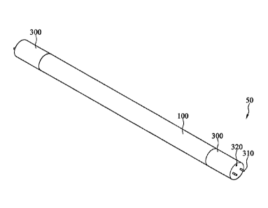
[0052] Referring to FIG 1 and FIG 2, the instant disclosure provides an
embodiment of
an LED tube lamp 50 which comprises a tube 100, an LED light strip 200, and
end caps
Date Recue/Date Received 2023-01-19
16
300. The LED light strip 200 is disposed inside the tube 100. Two end caps 300
are
respectively disposed on two ends of the tube 100. The LED tube lamp 100 can
be a
plastic tube, a glass tube, a plastic-metal combined tube, or a glass-metal
combined tube.
The two end caps 300 can have the same size or have different sizes. Referring
to FIG 2,
several LED light sources 202 are disposed on the LED light strip 200, and a
power supply
400 is disposed in the end cap 300. The power supply 400 may be in the form of
a single
integrated unit (e.g., with all components of the power supply 400 are within
a body)
disposed in an end cap 300 at one end of the tube 100. Alternatively, the
power supply 400
may be in form of two separate parts (e.g., with the components of the power
supply 400
.. are separated into two pieces) respectively disposed in two end caps 300.
The LED light
sources 202 and the power supply 400 can be electrically connected to each
other via the
LED light strip 200. The LED light strip 200 can be a bendable circuit sheet.
Moreover, in
some embodiments, the length of the bendable circuit sheet is greater than the
length of
the tube 100 (not including the length of the two end caps 300 respectively
connected to
two ends of the tube 100), or at least greater than a central portion of the
tube 100 between
two transition regions (e.g., where the circumference of the tube narrows) on
either end. In
one embodiment, the longitudinally projected length of the bendable circuit
sheet as the
LED light strip 200 is larger than the length of the tube 100. Middle part of
the LED light
strip 200 can be mounted on the inner surface of the tube 100. Instead, two
opposite, short
.. edges of the LED light strip 200 are not mounted on the inner surface of
the tube 100. The
LED light strip 200 comprises two freely extending end portions 210. The two
freely
extending end portions 210 are respectively disposed on the two opposite,
short edges of
the LED light strip 200. The two freely extending end portions 210
respectively extend
outside the tube 100 through two holes at two opposite ends of the tube 100
along the axial
direction of the tube 100. The two freely extending end portions 210 can
respectively
Date Recue/Date Received 2023-01-19
17
extend to inside area of the end caps 300 and can be electrically connected to
the power
supply 400. Each of the end caps 300 comprises a pair of hollow conductive
pins 310
utilized for being connected to an outer electrical power source. When the LED
tube lamp
50 is installed to a lamp base, the hollow conductive pins 310 are plugged
into
corresponding conductive sockets of the lamp base such that the LED tube lamp
50 can be
electrically connected to the lamp base. In one embodiment, the LED light
strip 2 includes
a bendable circuit sheet having a conductive wiring layer and a dielectric
layer that are
arranged in a stacked manner, wherein the wiring layer and the dielectric
layer have same
area or the wiring layer has a bit less area (not shown) than the dielectric
layer. The LED
light source 202 is disposed on one surface of the wiring layer, the
dielectric layer is
disposed on the other surface of the wiring layer that is away from the LED
light sources
202. The wiring layer is electrically connected to the power supply 400 to
carry direct
current (DC) signals. Meanwhile, the surface of the dielectric layer away from
the wiring
layer is fixed to the inner circumferential surface of the tube 100 by means
of the adhesive
sheet (not shown). The wiring layer can be a metal layer or a power supply
layer including
wires such as copper wires.
100531 In another embodiment, the outer surface of the wiring layer or the
dielectric
layer may be covered with a circuit protective layer made of an ink with
function of
resisting soldering and increasing reflectivity (not shown). Alternatively,
the dielectric
layer can be omitted and the wiring layer can be directly bonded to the inner
circumferential surface of the tube 100, and the outer surface of the wiring
layer is coated
with the circuit protective layer. Whether the wiring layer has a one-layered,
or
two-layered structure, the circuit protective layer can be adopted. In some
embodiments,
the circuit protective layer is disposed only on one side/surface of the LED
light strip 200,
such as the surface having the LED light source 202. In some embodiments, the
bendable
Date Recue/Date Received 2023-01-19
18
circuit sheet is a one-layered structure made of just one wiring layer, or a
two-layered
structure made of one wiring layer and one dielectric layer, and thus is more
bendable or
flexible to curl when compared with the conventional three-layered flexible
substrate (one
dielectric layer sandwiched with two wiring layers). As a result, the bendable
circuit sheet
of the LED light strip 200 can be installed in a tube with a customized shape
or
non-tubular shape, and fitly mounted to the inner surface of the tube 100. The
bendable
circuit sheet closely mounted to the inner surface of the tube 100nis
preferable in some
cases. In addition, using fewer layers of the bendable circuit sheet improves
the heat
dissipation and lowers the material cost.
[0054] Nevertheless, the bendable circuit sheet is not limited to being one-
layered or
two-layered; in other embodiments, the bendable circuit sheet may include
multiple layers
of the wiring layers and multiple layers of the dielectric layers, in which
the dielectric
layers and the wiring layers are sequentially stacked in a staggered manner,
respectively
(not shown). These stacked layers are away from the surface of the outermost
wiring layer
which has the LED light source 202 disposed thereon and is electrically
connected to the
power supply 400. Moreover, the projected length of the bendable circuit sheet
is greater
than the length of the tube 100.
[0055] In one embodiment, the LED light strip 200 includes a bendable circuit
sheet
having in sequence a first wiring layer, a dielectric layer, and a second
wiring layer (not
shown). The thickness of the second wiring layer is greater than that of the
first wiring
layer, and/or the projected length of the LED light strip 200 is greater than
that of the tube
100. The end region of the light strip 200 extending beyond the end portion of
the tube 100
without disposition of the light source 202 is formed with two separate
through holes to
respectively electrically communicate the first wiring layer and the second
wiring layer
(not shown). The through holes are not communicated to each other to avoid
short.
Date Recue/Date Received 2023-01-19
19
100561 In this way, the greater thickness of the second wiring layer allows
the second
wiring layer to support the first wiring layer and the dielectric layer, and
meanwhile allow
the LED light strip 200 to be mounted onto the inner circumferential surface
without being
liable to shift or deform, and thus the yield rate of product can be improved.
In addition,
the first wiring layer and the second wiring layer are in electrical
communication such that
the circuit layout of the first wiring later can be extended downward to the
second wiring
layer to reach the circuit layout of the entire LED light strip 200. In some
circumstances,
the first wiring connects the anode and the second wiring connects the
cathode. Moreover,
since the land for the circuit layout becomes two-layered, the area of each
single layer and
therefore the width of the LED light strip 200 can be reduced such that more
LED light
strips 200 can be put on a production line to increase productivity.
Furthermore, the first
wiring layer and the second wiring layer of the end region of the LED light
strip 200 that
extends beyond the end portion of the tube 100 without disposition of the
light source 202
can be used to accomplish the circuit layout of a power supply 400 so that the
power
supply 400 can be directly disposed on the bendable circuit sheet of the LED
light strip
200.
100571 As shown in FIG. 2, the tube 100 comprises two rear end regions 101,
two
transition regions, and one main body region 102. The two rear end regions 101
are at two
opposites ends of the main body region 102. The two transition regions are
respectively
between the two rear end regions 101 and the main body region 102. The two end
caps
300 are respectively connected to the two rear end regions 101. The rear end
regions 101
are the portions of the tube 100 shrunk in the radial direction. The rear end
regions 101
form shrunk holes. The bore of the rear end region 101 is less than that of
the main body
region 102. In other words, in the transition region, the tube 100 narrows, or
tapers to have
.. a smaller diameter when moving along the length of the tube 100 from the
main body
Date Recue/Date Received 2023-01-19
20
region 102 to the rear end region 101. The tapering/narrowing may occur in a
continuous,
smooth manner (e.g., to be a smooth curve without any linear angles). By
avoiding
angles, in particular any acute angles, the tube 100 is less likely to break
or crack under
pressure. Furthermore, the transition region is formed by two curves at both
ends, wherein
.. one curve is toward inside of the tube 100 and the other curve is toward
outside of the tube
100. For example, one curve closer to the main body region 102 is convex from
the
perspective of an inside of the tube 100 and one curve closer to the rear end
region 101 is
concave from the perspective of an inside of the tube 100. The transition
region of the
tube 100 in one embodiment includes only smooth curves, and does not include
any
angled surface portions. As shown in FIG 1, the appearance of the LED tube
lamp 50 is
identical from the tube 100 to the end caps 300, meaning that the outer
surfaces of the end
caps 300 are aligned with that of the tube 100.
100581 Referring to FIG 3 and FIG 4, FIG 3 is a partial view of the LED tube
lamp 50,
and FIG 4 is a cross section of FIG 3 along the line A-A'. The end cap 300 of
the
.. embodiment further comprises a lateral wall 301, an end wall 302, and an
opening 320.
The lateral wall 301 is tubular shape. The lateral wall 301 and the tube 100
are coaxial and
are connected to each other. More specifically, the lateral wall 301 and the
tube 100 are
substantially coaxial but the alignment of the axial directions of the lateral
wall 301 and
the tube 100 may have a slightly shift due to manufacturing tolerance. The end
wall 302 is
substantially perpendicular to the axial direction of the lateral wall 301.
The end wall 302
is connected to an end of the lateral wall 301 away from the tube 100. More
specifically,
the end wall 302 is substantially perpendicular to the axial direction of the
lateral wall 301
but the angle between the end wall 302 and the axial direction of the lateral
wall 301 may
not be exactly 90 degrees maybe due to manufacturing tolerance. This is still
within the
scope of substantially perpendicular. Even if the end wall 302 relative to the
axial direction
Date Recue/Date Received 2023-01-19
21
of the lateral wall 301 is slightly inclined, the end wall 302 and the lateral
wall 301 can
still form a receiving space for receiving the power supply 400 and can mate
the lamp base.
The end wall 302 and the lateral wall 301 form an inner space of the end cap
300. The
power supply 400 is disposed in the inner space of the end cap 300. The
opening 320
penetrates through the end wall 302. The inner space of the end cap 300 can
communicate
with outside area through the opening 320. Air can flow through the opening
320 between
the inner space of the end cap 300 and outside area. Moreover, the opening 320
is good for
pressure releasing, and a light sensor can be configured inside the end cap
300 to collimate
with the opening 320 for light detection and electric-shock prevention during
installation
of the LED tube lamp 50 to a lamp base (not shown).
[0059] The power supply 400 can be a module, e.g., an integrated power module.
The
power supply 400 may be in the form of a single integrated unit (e.g., with
all components
of the power supply 400 are within a body) disposed in an end cap 300 at one
end of the
tube 100. Alternatively, the power supply 400 may be in form of two separate
parts (e.g.,
with the components of the power supply 400 are separated into two pieces)
respectively
disposed in two end caps 300. The power supply 400 further comprises a pair of
metal
wires 410. The metal wires 410 extend from the power supply 400 to the inside
of the
hollow conductive pins 310 and are connected to the hollow conductive pins
310. In other
words, the power supply 400 can be electrically connected to the outer
electrical power
source through the metal wires 410 and the hollow conductive pins 310. The
hollow
conductive pins 310 are disposed outside the end wall 302 and extend along the
axial
direction of the lateral wall 301. Referring to FIG. 4, when the LED tube lamp
50 is
installed to a horizontal lamp base (not shown), the axle of the lateral wall
301 is
substantially parallel with the horizontal direction "H", and the pair of the
hollow
conductive pins 310 are at the same altitude and overlap each other in the
vertical direction
Date Recue/Date Received 2023-01-19
22
"V". Under the circumstances, the altitude of the opening 320 is higher than
that of the
axle of the lateral wall 301 in the vertical direction "V".
[0060] In the embodiment, as shown in FIG. 4, the axial direction of the
opening 320 is
substantially parallel with that of the lateral wall 301. The axial direction
of the opening
.. 320 is defined as an extending direction of the opening 320 extending from
the inner
surface of the end wall 302 (the surface inside the end cap 300) to the outer
surface of the
end wall 302 (the surface outside). In the embodiment, the opening 320 is
substantially
aligned with the inner surface of the lateral wall 301 (the surface inside the
end cap 300).
Specifically, a part of the inner surface of the opening 320 is substantially
aligned with a
part of the inner surface of the lateral wall 301.
[0061] In the embodiment, as shown in FIG 4, an end wall radius "r" is defined
as the
shortest distance between the center of the end wall 302 (the point of the end
wall 302
through which the axle of the lateral wall 301 passes) and the periphery of
the end wall
302 in the radial direction of the end cap 300 (the direction substantially
parallel with the
vertical direction "V" shown in FIG 4). A distance "L" is defined as the
shortest distance
between the center of the end wall 302 and the opening 320 in the radial
direction of the
end cap 300. The distance "L" is from 2/5 to 4/5 of the end wall radius "r".
That is to say,
the relation of the opening 320 and the end wall 302 matches an equation
listed below:
[0062] 0.4r. L. 0.8r
[0063] When the position of the opening 320 relative to the center of the end
wall 302
matches the aforementioned equation, the convection of air between the LED
tube lamp
50 and outside area can be more efficiently.
[0064] Referring to FIG 5, the difference between the LED tube lamps 50 of FIG
5 and
FIG 4 is the forms of the openings 320. In the embodiment, as shown in FIG. 5,
the
opening 320 can be inclined. The axial direction of the opening 320 and the
axial direction
Date Recue/Date Received 2023-01-19
23
of the lateral wall 301 define an angle 01. The angle 01 is an acute angle.
The axial
direction of the opening 320 is defined as an extending direction of the
opening 320
extending from the inner surface of the end wall 302 to the outer surface of
the end wall
302. When the LED tube lamp 50 is installed to the horizontal lamp base, the
axial
directions of the tube 100 and the end cap 300 are substantially parallel with
the horizontal
direction "H", and the altitude of the opening 320 is higher than that of the
axle of the tube
100 and the end cap 300 in the vertical direction "V". When the power supply
400
generates heat in operation, the inclined opening 320 shown in FIG 5 is
beneficial to the
process that heated air rises (along the vertical direction "V") and flows to
outside area
through the opening 320.
[0065] Additionally, two openings 320 are acceptable. As shown in FIG 5, two
inclined
openings 320 are substantially symmetrical to each other. When the LED tube
lamp 50 is
installed to the horizontal lamp base, the axial directions of the tube 100
and the end cap
300 are substantially parallel with the horizontal direction "H", and the
altitude of one of
the two openings 320 is higher than that of the axle of the tube 100 and the
end cap 300 in
the vertical direction "V" while the other one of the two openings 320 is
lower than that of
the axle of the tube 100 and the end cap 300 in the vertical direction "V".
Each of the axial
directions of the two openings 320 and the axial direction of the lateral wall
301
respectively define an acute angle. When the power supply 400 generates heat
in operation,
the upper opening 320 shown in FIG 5 is beneficial to the process that heated
air rises
(along the vertical direction "V") and flows to outside area through the upper
opening 320,
and the lower opening 320 shown in FIG 5 is beneficial to the process that
cool air from
outside area flow to inside of the end cap 300 through the lower opening 320.
As a result,
convection of the heated air and cool air is improved, and, consequently, the
effect of heat
dissipation is better.
Date Recue/Date Received 2023-01-19
24
[0066] Referring to FIG 6, the difference between the LED tube lamps 50 of FIG
6 and
FIG 4 is the forms of the openings 320. As shown in FIG 6, the opening 320 is
not aligned
with the inner surface of the lateral wall 301. Comparing to the opening 320
of FIG 4, the
opening 320 of FIG 6 is away from the end wall 302.
[0067] If the opening 320 is too large, dust from outside area may easily pass
through
the opening 320 and enter the inner space of the end cap 300. Dust may
accumulate on the
power supply 400 and negatively affect the effect of heat dissipation. To
prevent dust from
passing through the opening 320, the radial area of the opening 320 is
preferably less than
1/10 of the radial area of the end wall 302. Under the circumstances, dust is
restricted to
pass through the opening 320 to enter the inner space of the end cap 300. In
an example
that the LED tube lamp 50 is a T8 tube lamp of which the external diameter of
the tube
100 is 25 mm to 28 mm, and the external diameter of the end cap 300 (i.e., the
diameter of
the end wall 302 in the vertical direction "V" shown in FIG 4) is equal to
that of the tube
100. If the diameter of the end wall 302 in the vertical direction "V" shown
in FIG 4 is 25
mm, the area of the end wall 302 in the vertical direction "V" is 490.625 mm2
(square of
the radius of the end wall 302 times 3.14), and the bore area (the radial
area) of the
opening 320 in the vertical direction "V" is 0.5 mm2 to 6 mm2. For example,
the radial
area of the opening 320 is 6 mm2 and the radial area of the end wall 302 is
490.625 mm2,
the radial area of the opening 320 is about 1/100 of the radial area of the
end wall 302.
Under the circumstances, dust is hard to pass through the opening 320 to enter
the inner
space of the end cap 300. In different embodiments, the bore area (the radial
area) of the
opening 320 in the vertical direction "V" is 0.5 mm2 to 3 mm2. Under the
circumstances,
dust is much harder to pass through the opening 320 to enter the inner space
of the end cap
300.
100681 In different embodiments, the end cap 300 further comprises a dust-
proof net
Date Recue/Date Received 2023-01-19
25
(not shown). The dust-proof net is a net with fine meshes. The dust-proof net
can cover the
opening 320. For example, the dust-proof net can be mounted on the outer
surface or the
inner surface of the end wall 302 and cover the opening 320. As a result, the
dust-proof net
can prevent dust from entering the opening 320 and keep ventilation well.
[0069] Referring to FIG 7, the difference between the end caps 300 of FIG 7
and FIG 3
is the forms of the openings 320. The opening 320 shown in FIG 3 is a circular
opening.
In the embodiment, the opening 320 shown in FIG 7 is an arc-shaped opening
which is
long and flat. The opening 320 shown in FIG 7 includes two opposite long edges
3201 (arc
edges) and two opposite short edges 320s between the two long edges 3201. The
opening
320 has an interval "I" which is the shortest distance between the two long
edges 3201.
Under the circumstances, the interval "I" of the opening 320 is much shorter
than the
length of the long edge 3201. Even if the interval "I" of the opening 320 is
equal to or
slightly less than the diameter (i.e., the bore) of the opening 320 shown in
FIG 3, the bore
area of the opening 320 shown in FIG 7 is still greater than that of the
opening 320 shown
in FIG 3. As a result, the opening 320 of FIG 7 can not only prevent most of
the dust from
passing through but also keep ventilation well. In an embodiment, the distance
of the
interval "I" of the opening is between 0.5 mm to 1.5 mm, and the length of the
long edge
3201 of the opening is between 1 mm to 7 mm.
[0070] In different embodiments, the number, the shape, the position, or the
arrangement of the opening(s) 320 can be varied according to different design.
Details are
described below.
[0071] Referring to FIG 8, the difference between the end caps 300 of FIG 8
and FIG 7
is the amount and forms of the openings 320. In the embodiment, there are two
openings
320 shown in FIG 8, and the two openings 320 are substantially symmetrical to
each other.
The two symmetrical openings 320 shown in FIG 8 are beneficial to convection
of heated
Date Recue/Date Received 2023-01-19
26
air and cool air. The better the convection is, the better the effect of heat
dissipation is.
100721 Referring to FIG 9, the difference between the end caps 300 of FIG 9
and FIG 7
is the amount and forms of the openings 320. In the embodiment, there are two
openings
320 shown in FIG 9, and the two openings 320 are adjacent to each other. Under
the
.. circumstances that the interval between the two long edges of either
opening 320 shown in
FIG 9 is substantially equal to that of the opening 320 shown in FIG 7, the
sum of the
bore areas of the two adjacent openings 320 shown in FIG 9 is greater than the
bore area
of the single opening 320 shown in FIG 7. The two adjacent openings 320 shown
in FIG 9
are not only beneficial to convection but also beneficial to prevent most of
the dust from
passing through the opening 320 and entering the end cap 300.
100731 Referring to FIG 10, the difference between the end caps 300 of FIG 10
and FIG
9 is the amount and forms of the openings 320. In the embodiment, there are
two set of
two openings 320 shown in FIG 10, and the two set of two openings 320 are
symmetrical
to each other. The two set of two openings 320 shown in FIG 10 are not only
beneficial to
.. convection of heated air and cool air but also beneficial to prevent dust
from passing
through the opening 320 and entering the end cap 300.
100741 Referring to FIG 11, the difference between the end caps 300 of FIG 11
and FIG
9 is the forms of the openings 320. The two short edges opposite to each other
of each
opening 320 shown in FIG 9 are round. In the embodiment, the two short edges
opposite
to each other of each opening 320 shown in FIG 11 are rectangular. Referring
to FIG 12,
the difference between the end caps 300 of FIG. 12 and FIG 10 is the forms of
the
openings 320. The two short edges opposite to each other of each opening 320
shown in
FIG 10 are round. In the embodiment, the two short edges opposite to each
other of each
opening 320 shown in FIG 12 are rectangular. In different embodiments, the
opening 320
can be a long, narrow and straight shaped opening.
Date Recue/Date Received 2023-01-19
27
100751 Referring to FIG 13, the difference between the end caps 300 of FIG 13
and FIG
3 is the amount and forms of the openings 320. In the embodiment, the end cap
300 shown
in FIG 13 comprises several openings 320. The openings 320 are a plurality of
circular
shaped openings and are asymmetrically arranged on the end wall 302. Referring
to FIG 3
and FIG 13, when the LED tube lamp 50 is installed to the horizontal lamp
base, the axial
directions of the tube 100 and the end cap 300 are substantially parallel with
the horizontal
direction "H", and the altitude of at least one of the openings 320 shown in
FIG 13 is
higher than that of the axle of the tube 100 and the end cap 300 in the
vertical direction
"V". In the embodiment, the altitudes of all of the openings 320 shown in FIG
13 are
higher than that of the axle of the tube 100 and the end cap 300 in the
vertical direction
"V". In different embodiments, the openings 320 symmetrically arranged on the
end wall
302 have different shapes, e.g., a long, circular shape. Moreover, at least a
part of at least
one of the openings 320 is higher than the axle of the tube 100 and the end
cap 300 in the
vertical direction "V".
[0076] Referring to FIG 14, the difference between the end caps 300 of FIG 14
and FIG
13 is the amount, arrangement, and forms of the openings 320. In the
embodiment, the end
cap 300 shown in FIG 14 comprises several openings 320, and the openings 320
relative
to the axle of the end cap 300 are symmetrical. The openings 320 are arranged
on the end
wall 302 and are around the axle of the end cap 300 in point symmetry.
[0077] Referring to FIG 15, the differences between the LED tube lamps 50 of
FIG 15
and FIG 4 are the forms of the power supply 400 and the opening 320. The power
supply
400 shown in FIG. 15 comprises a printed circuit board 420 and one or more
electronic
components 430. The printed circuit board 420 comprises a first surface 421
and a second
surface 422 opposite to and substantially parallel with each other. The first
surface 421 and
the second surface 422 of the printed circuit board 420 are perpendicular to
the axial
Date Recue/Date Received 2023-01-19
28
direction of the lateral wall 301. The second surface 422 of the printed
circuit board 420
relative to the first surface 421 is closer to the end wall 302 of the end cap
300 which at
least part of the power supply 400 is thereon. The electronic components 430
are disposed
on the first surface 421 of the printed circuit board 420. The electronic
components 430
can be, for example, capacitors.
[0078] In the embodiment, as shown in FIG 15, the second surface 422 of the
printed
circuit board 420 contacts the inner surface of the end wall 302. Moreover,
the metal wires
410 (not shown in FIG 15) of the power supply 400 can be directly inserted in
the hollow
conductive pins 310 from the printed circuit board 420. Alternatively, the
hollow
conductive pins 310 can be directly contacted by a pair of corresponding
contacts (not
shown) on the second surface 422 of the printed circuit board 420. In
addition, the freely
extending end portion 210 is connected to the first surface 421 of the printed
circuit board
420. In different embodiments, the second surface 422 of the printed circuit
board 420
does not contact the inner surface of the end wall 302 and instead the second
surface 422
of the printed circuit board 420 is spaced from the inner surface of the end
wall 302 by a
predetermined interval. The interval between the printed circuit board 420 and
the end
wall 302 is beneficial to convection of air. In addition, the freely extending
end portion
210 is connected to the second surface 422 of the printed circuit board 420
(not shown).
[0079] In the embodiment, as shown in FIG 15, the second surface 422 of the
printed
circuit board 420 fully contacts the inner surface of the end wall 302 and
covers the
opening 320; therefore, heat generated by the printed circuit board 420 can be
directly
transferred to cool air outside the end cap 300 through the opening 320 and,
consequently,
the effect of heat dissipation is well. Furthermore, under the circumstances
that the second
surface 422 of the printed circuit board 420 fully covers the opening 320,
dust is blocked
by the printed circuit board 420 so that dust won't pass through the opening
320 to enter
Date Recue/Date Received 2023-01-19
29
the inner space of the end cap 300. Thus, the bore area of the opening 320
shown in FIG
15 can be greater than that of the opening 320 shown in FIG 4.
100801 In different embodiments, the second surface 422 of the printed circuit
board
420 contacts the inner surface of the end wall 302 while the end cap 300 has
no opening
320. In the situation, the end wall 302 can comprise a material with high
thermal
conductivity. The end wall 302, for example, can be made by composite
materials. The
part of the end wall 320 which is connected to the hollow conductive pins 310
is made by
an insulating material, and the other part of the end wall 320 is made by
aluminum. Heat
generated by the printed circuit board 420 can be directly transferred to the
part of
aluminum of the end wall 302 and then can be transferred to cool air outside
the end cap
300 through the part of Aluminum; therefore, the effect of heat dissipation is
well. In
different embodiments, the opening 320 can be disposed on the lateral wall 301
such that
when the LED tube lamp 50 is installed to the horizontal lamp base, the
altitude of the
opening 320 on the lateral wall 301 is higher than that of the axle of the
tube 100 and the
end cap 300 in the vertical direction "V".
100811 Referring to FIG 16, the difference between the LED tube lamps 50 of
FIG 16
and FIG 15 is that the power supply 400 shown in FIG 16 further comprises a
heat-dissipating element or a driving module 440. The heat-dissipating element
or driving
module 440 is disposed on the second surface 422 of the printed circuit board
420 and
extends into the opening 320. In an embodiment, the heat-dissipating element
440a is a
metal heat pipe or a metal fin. Heat generated by electronic components 430 on
the printed
circuit board 420 can be transferred to the heat-dissipating element 440a and
then can be
transferred to cool air outside the end cap 300 through the heat-dissipating
element 440a;
therefore, the effect of heat dissipation is well. Since the driving module
440b is a main
heat source among the electronic components of the power supply 400, the idea
of
Date Recue/Date Received 2023-01-19
30
separation of the general electronic components 430 (the general electronic
components
430 generating less heat than the driving module 440b) and the driving module
440b is
beneficial to improve the effect of heat dissipation. For example, the general
electronic
components 430 are disposed on the first surface 421 of the printed circuit
board 420 and
the driving module 440b generating significant heat is disposed on the second
surface 422
of the printed circuit board 420 and locates adjacently to the at least one
opening 320. The
heat-dissipating element or driving module 440 can be disposed in the opening
320 such
that the heat generated by the driving module 440b or the heat of heat-
dissipating element
can be directly transferred to cool air outside the end cap 300; therefore,
the effect of heat
dissipation is improved. The driving module 440b comprises one or more
specific
electronic components generating significant heat including an inductor, a
transistor, or an
integrated circuit. The arrangement of having the inductor, the transistor, or
the integrated
circuit positioned in the opening 320 is beneficial to improve the effect of
heat dissipation.
100821 In different embodiments, several heat-dissipating elements or driving
modules
.. 440 of the power supply 400 can be respectively disposed in several
openings 320. For
example, the inductor, the transistor, and the integrated circuit can be
respectively
disposed in different openings 320. Alternatively, the heat-dissipating
element, the
inductor, the transistor, and the integrated circuit can be respectively
disposed in different
openings 320.
100831 Referring to FIG 16 and FIG 17, the difference between FIG 16 and FIG
17 is
whether the heat-dissipating element or driving module 440 and the opening 320
are
sealed in the radial direction of the opening 320. The heat-dissipating
element or driving
module 440 (the heat-dissipating element 440a in the example) and the opening
320
shown in FIG. 16 are sealed, which means that the shape and the size of the
cross section
.. of the heat-dissipating element or driving module 440 in the radial
direction exactly match
Date Recue/Date Received 2023-01-19
31
the shape and the size of the bore of the opening 320 in the radial direction.
In one
embodiment, at least one component of the heat-dissipating element or the
driving module
440 and the at least one opening 320 are substantially sealed in the radial
direction of the
at least one opening. Instead, there is a gap "G" between the heat-dissipating
element or
driving module 440 (the driving module 440b in the example) and the opening
320 in the
radial direction shown in FIG. 17. Thus the outside air can freely flow
through the gap "G"
to enter the end cap 300 while the heat-dissipating element or driving module
440 is in the
opening 320. The effect that the heat-dissipating element or driving module
440 and the
opening 320 are sealed in the radial direction is not the same as the effect
of air tight.
There may be small gaps hard to be seen by eyes but still exist between the
heat-dissipating element or driving module 440 and the opening 320 shown in
FIG 16.
However, the small gaps between the heat-dissipating element or driving module
440 and
the opening 320 shown in FIG 16 is much smaller than the gap "G" shown in FIG
17 and,
consequently, the heat-dissipating element or driving module 440 and the
opening 320
shown in FIG 16 block cool air outside the opening 320 to a great extent.
100841 Referring to FIG 18, the differences between the LED tube lamps 50 of
FIG 18
and FIG 4 are the forms of the power supply 400. The power supply 400 shown in
FIG 18
comprises a printed circuit board 420, one or more electronic components 430,
and a
heat-dissipating element or driving module 440. The printed circuit board 420
comprises a
first surface 421 and a second surface 422 opposite to and substantially
parallel with each
other. The first surface 421 and the second surface 422 of the printed circuit
board 420 are
substantially parallel with the axial direction of the lateral wall 301. The
electronic
components 430 and the heat-dissipating element or driving module 440 (the
driving
module 440b in the example) are all disposed on the first surface 421 of the
printed circuit
board 420. The heat-dissipating element or driving module 440 relative to the
electronic
Date Recue/Date Received 2023-01-19
32
components 430 is closer to the opening 320. In an embodiment, the heat-
dissipating
element 440a is a metal heat pipe or a metal fin. Heat generated by the
printed circuit
board 420 can be transferred to the heat-dissipating element 440a. Since the
heat-dissipating element 440a relative to the electronic components 430 is
closer to the
opening 320, it is beneficial to heat exchange between the heat-dissipating
element 440a
and outside cool air, and, consequently, the effect of heat dissipation is
better. In an
embodiment, the driving module 440b relative to the electronic components 430
(the
general electronic components generating less heat than the driving module
440b) is closer
to the opening 320, which is beneficial to heat exchange between the driving
module 440b
and outside cool air. Thus the effect of heat dissipation is better. The
driving module 440b
comprises one or more specific electronic components generating significant
heat. The
specific electronic components includes an inductor, a transistor, or an
integrated circuit.
The arrangement that the inductor, the transistor, or the integrated circuit
relative to the
general electronic components 430 is closer to the opening 320 is beneficial
to improve
the effect of heat dissipation.
100851 Referring to FIG 19, FIG 19 is a part of a cross section of the LED
tube lamp 50
installed to a lamp base 60. The LED tube lamp 50 shown in FIG 19 comprises a
coupling
structure. A part of the coupling structure is disposed on the rear end region
101 of the
tube 100, and the other part of the coupling structure is disposed on the end
cap 300. The
tube 100 and the end cap 300 can be connected to each other by the coupling
structure.
The coupling structure comprises a first thread 3001 disposed on the lateral
wall 301 and a
second thread 1001 disposed on the rear end region 101 of the tube 100. The
first thread
3001 is on the inner surface of the lateral wall 301 and is at an end of the
lateral wall 301
away from the end wall 302. The second thread 1001 is on the outer surface of
the rear end
region 101 of the tube 100 and is close to the open end of the tube 100 (i.e.,
the two
Date Recue/Date Received 2023-01-19
33
opposite ends of the tube 100). The first thread 3001 is corresponding to the
second thread
1001. The end cap 300 can be connected to the tube 100 by relative rotation of
the first
thread 3001 and the second thread 1001. Based on the coupling structure, the
end cap 300
can be easily assembled to the tube 100 or disassembled from the tube 100.
.. [0086] As shown in FIG 19, in the embodiment, when the relative rotation of
the first
thread 3001 and the second thread 1001 is done and the first thread 3001 fully
matches the
second thread 1001 (i.e., the end cap 300 is properly assembled to the tube
100), the
opening 320 is rotated about the axle of the tube 100 to a predetermined
position.
Specifically, while the lamp base 60 is horizontal or substantially horizontal
and the LED
tube lamp 50 is horizontally installed to the lamp base 60, the axial
directions of the tube
100 and the end cap 300 are substantially parallel with the horizontal
direction "H", and
the predetermined position means that the altitude of the opening 320 is
higher than that of
the axle of the lateral wall 302 in the vertical direction "V" in the
configuration.
[0087] As shown in FIG 19, in the embodiment, the coupling structure further
comprises a first positioning unit 3002 disposed on the lateral wall 301 and a
second
positioning unit 1002 disposed on the rear end region 101 of the tube 100. The
first
positioning unit 3002 is corresponding to the second positioning unit 1002.
When the
relative rotation of the first thread 3001 and the second thread 1001 is done
and the first
thread 3001 fully matches the second thread 1001, the first positioning unit
3002 mates the
second positioning unit 1002, such that the tube 100 and the end cap 300 are
positioned to
each other. In the embodiment, the first positioning unit 3002 is a concave
point on the
inner surface of the lateral wall 301, and the second positioning unit 1002 is
a convex
point on the outer surface of the rear end region 101 of the tube 100. When
the first thread
3001 fully matches the second thread 1001, the convex point of the second
positioning
unit 1002 falls in the concave point of the first positioning unit 3002 to
assist the fixation
Date Recue/Date Received 2023-01-19
34
of the LED tube lamp 50 and to inform people assembling the LED tube lamp 50
that the
end cap 300 has been properly assembled to the tube 100. More particularly,
when the first
positioning unit 3002 and the second positioning unit 1002 are coupled to each
other along
with slightly sound and vibration, people assembling the LED tube lamp 50 can
be
informed by hearing the sound or feeling the vibration and can immediately
realize that
the end cap 300 has been properly assembled to the tube 100. In the assembling
process of
the LED tube lamp 50, operator, based on the sound and the vibration generated
by the
mating (coupling) of the first positioning unit 3002 and the second
positioning unit 1002,
can finish the assembling process of an assembled LED tube lamp 50 in time.
Thus the
efficiency of assembling can be improved.
[0088] In different embodiments, the first positioning unit 3002 can be a
convex point,
and the second positioning unit 1002 can be a concave point. In different
embodiments,
the first positioning unit 3002 and the second positioning unit 1002 can
respectively be
disposed on different positions of the end cap 300 and the rear end region 101
of the tube
100 on the premise that the first positioning unit 3002 mates the second
positioning unit
1002 only when the end cap 300 is properly assembled to the tube 100.
[0089] As shown in FIG 19, the method of having the LED tube lamp 50 installed
to
the lamp base 60 is: plugging the hollow conductive pins 310 of the end cap
300 into the
conductive sockets 61 of the lamp base 60, and rotating the LED tube lamp 50
about the
axle of the tube 100 and the end cap 300 until the hollow conductive pins 310
in the
conductive sockets 61 are rotated to a predetermined position. The assembling
is done
when the hollow conductive pins 310 in the conductive sockets 61 are in the
predetermined position.
[0090] In the embodiment, torque applied to the tube 100 and the end cap 300
to have
the first thread 3001 and the second thread 1001 relatively rotated until the
first thread
Date Recue/Date Received 2023-01-19
35
3001 fully matches the second thread 1001 is greater than that applied to the
LED tube
lamp 50 to have the LED tube lamp 50 installed to the lamp base 60 (i.e.,
torque for
rotating the hollow conductive pins 310 in the conductive sockets 61). In
other words,
friction force between the first thread 3001 and the second thread 1001 of the
assembled
.. LED tube lamp 50 is greater than that between the hollow conductive pins
310 and the
conductive sockets 61 when the LED tube lamp 50 is installed to the lamp base
60. In an
embodiment, the friction force between the first thread 3001 and the second
thread 1001 is
at least twice greater than that between the hollow conductive pins 310 and
the conductive
sockets 61. When the installed LED tube lamp 50 is going to be uninstalled
from the lamp
.. base 60, the hollow conductive pins 310 in the conductive sockets 61 have
to be reversely
rotated to a predetermined position in advance, and then the LED tube lamp 50
can be
unplugged from the lamp base 60 (i.e., the hollow conductive pins 310 can be
unplugged
from the conductive sockets 61). Since the friction force between the first
thread 3001 and
the second thread 1001 is greater than that between the hollow conductive pins
310 and
the conductive sockets 61, the relative position of the first thread 3001 and
the second
thread 1001 remains still during the reverse rotation of the hollow conductive
pins 310 in
the conductive sockets 61. As a result, the end cap 300 won't accidentally
loose from the
tube 100 during the process of uninstalling the LED tube lamp 50 from the lamp
base 60.
100911 Referring to FIG 20, FIG 20 is a part of a cross section of the LED
tube lamp 50
installed to the lamp base 60, the difference between the LED tube lamps 50 of
the FIG 20
and FIG 19 is with respect to the coupling structures. As shown in FIG 20, the
coupling
structure comprises an annular convex portion 3003 disposed on the lateral
wall 301 and
an annular trough 1003 disposed on the rear end region 101 of the tube 100.
The annular
convex portion 3003 is on the inner surface of the lateral wall 301 and is at
an end of the
.. lateral wall 301 away from the end wall 302. The annular trough 1003 is on
the outer
Date Recue/Date Received 2023-01-19
36
surface of the rear end region 101 of the tube 100. The annular convex portion
3003 is
corresponding to the annular trough 1003. The end cap 300 can be connected to
the tube
100 by the coupling of the annular convex portion 3003 and the annular trough
1003. The
annular convex portion 3003 and the annular trough 1003 are rotatably
connected to each
other. More particularly, the annular convex portion 3003 is capable of
sliding along the
annular trough 1003, and, consequently, the tube 100 and the end cap 300 have
a degree of
freedom capable of rotating relative to each other about the axle of the tube
100 and the
end cap 300 by the annular convex portion 3003 and the annular trough 1003.
[0092] As shown in FIG 20, in the embodiment, the coupling structure further
comprises a first positioning unit 3002 disposed on the lateral wall 301 and a
second
positioning unit 1002 disposed on the rear end region 101 of the tube 100. The
structure
and the function of the first positioning unit 3002 and the second positioning
unit 1002 are
described above and there is no need to repeat. Although the tube 100 and the
end cap 300
are rotatably connected to each other by the coupling of the annular convex
portion 3003
and the annular trough 1003, the first positioning unit 3002 mates the second
positioning
unit 1002 (e.g., the concave point of the first positioning unit 3002 and the
convex point of
the second positioning unit 1002 are coupled to each other) when the tube 100
and the end
cap 300 are rotated relative to each other to a predetermined position to
assist the
positioning in the assembling process of the tube 100 and the end cap 300 and
to enhance
the fixation of the tube 100 and the end cap 300. Based on the coupling
structure, the end
cap 300 can be easily assembled to the tube 100 or disassembled from the tube
100.
[0093] As shown in FIG 20, in the embodiment, the rear end regions 101 of the
tube
100 utilized for being connected to the end cap 300 is shrunk in the radial
direction. The
extent that the rear end regions 101 shrunk (i.e., difference between the main
body region
102 and the rear end regions 101 in radial direction) is equivalent to the
thickness of the
Date Recue/Date Received 2023-01-19
37
lateral wall 301 of the end cap 300. Thus the outer surface of the lateral
wall 301 of the
end cap 300 is aligned with the outer surface of the main body region 102 of
the tube 100
while the end cap 300 and the tube 100 are connected to each other.
100941 In different embodiments, the annular trough 1003 can be disposed on
the lateral
.. wall 301, and the annular convex portion 3003 can be disposed on the rear
end region 101
of the tube 100. Additionally, the coupling structure can further comprise a
hot melt
adhesive. The hot melt adhesive can be disposed in the joint of the tube 100
and the end
cap 300 (e.g., between the rear end region 101 and the lateral wall 301). When
assembling
the tube 100 and the end cap 300, the end cap 300 can be assembled to the tube
100 via the
coupling structure in advance, and the hot melt adhesive is in liquid state in
the assembling
process. After heating up the hot melt adhesive, and upon expansion due to
heat absorption,
the hot melt adhesive flows, and then solidifies upon cooling, thereby bonding
together the
end cap 300 to the tube 100 (not shown). The volume of the hot melt adhesive
may expand
to about 1.3 times the original size when heated from room temperature (e.g.,
between
about 15 and 30 degrees Celsius) to about 200 to 250 degrees Celsius. The end
cap 300
and the end of the tube 100 could be secured by using the hot melt adhesive
and therefore
qualified in a torque test of about 1.5 to about 5 newton-meters (Nt-m) and/or
in a bending
test of about 5 to about 10 newton-meters (Nt-m). During the heating and
solidification of
the hot melt adhesive, the heat and pressure inside the end cap increase and
are then
released through the at least one opening 320 on the end cap 300. After the
hot melt
adhesive hardens, the end cap 300 can be firmly fixed to the tube 100. Under
the
circumstances, the end cap 300 and the tube 100 is hard to disassemble unless
the
hardened hot melt adhesive returns to liquid state by certain process. The
design of the
LED tube lamp 50 is to take into account both the convenience regarding the
assembling
.. process of the LED tube lamp 50 and the robustness regarding the assembled
LED tube
Date Recue/Date Received 2023-01-19
38
lamp 50.
[0095] Referring to FIG 21, FIG 21 is a perspective view of the LED tube lamp
50
installed to an inclined lamp base 60. In different embodiments, the LED tube
lamp 50 can
be installed to an inclined or a vertical lamp base 60 in an inclined or
vertical pose. In the
embodiment, as shown in FIG. 21, the lamp base 60 is inclined. Thus the axle
of the LED
tube lamp 50 and the horizontal direction "H" define an acute angle while the
LED tube
lamp 50 is installed to the lamp base 60. Under the circumstances that the LED
tube lamp
50 installed to the lamp base 60 is inclined, the altitude of the opening 320
of the end cap
300 is still higher than that of the axle of the LED tube lamp 50 in the
vertical direction
"V", which is beneficial to improve the effect of heat dissipation.
[0096] Referring to FIGS. 22, 23 and 24, FIG 22 is a partial view of the LED
tube lamp
50, FIG 23 is a cross section of FIG 22 along the line B-B', and FIG 24 is a
partially
cross section of FIG 22. Wherein a part of components of the end cap 300 is
not shown in
FIG 24. The difference between the end cap 300 of FIGS. 22 to 24 and the end
cap 300 of
FIG 3 is the forms of the openings 320. Additionally, the end cap 300 of FIGS.
22 to 24
further comprises two vertical ribs 330, and the vertical ribs 330 are
utilized for fixation of
the printed circuit board 420 of the power supply 400. Thus the relative
position between
the printed circuit board 420 of the power supply 400 and the end cap 300 of
FIGS. 22 to
24 can be varied based on the shape of the vertical ribs 300.
[0097] As shown in FIG 22, in the embodiment, the opening 320 has a bow-shaped
opening. The size and the position of the opening 320 are corresponding to the
two vertical
ribs 330. That is to say, the two vertical ribs can be seen from outside the
opening 320 in
the viewing angle which is substantially parallel with and is along the axial
direction of the
end cap 300. Furthermore, the two vertical ribs 330 are disposed on the inner
surface of
the lateral wall 301, and the two vertical ribs are spaced from each other and
extend along
Date Recue/Date Received 2023-01-19
39
the axial direction of the lateral wall 301. The vertical ribs 330 are
perpendicular to a plane
at which the printed circuit board 420 of the power supply 400 is located. In
other words,
the two vertical ribs 330 are perpendicular to a side of the printed circuit
board 420 of the
power supply 400 in the radial direction of the end cap 300. For illustration,
as shown in
FIG 23, when the LED tube lamp 50 is horizontally installed, the axial
directions of the
end cap 300 is substantially parallel with the horizontal direction "if', and
the vertical ribs
300 extend from the inner surface of the lateral wall 301 along the vertical
direction "V"
and is connected to the printed circuit board 420 of the power supply 400.
[0098] As shown in FIG 23 and FIG 24, the vertical rib 330 comprises a first
side 331,
a second side 332, and a third side 333. The first side 331 and the second
side 332 are
opposite to each other. The second side 332 relative to the first side 331 is
closer to the
opening 320. The third side 333 is away from the lateral wall 301 and is
between the first
side 331 and the second side 332. The third side 333 is connected to the
printed circuit
board 420 of the power supply 400. The third side 333 is, but is not limited
to, adhered to
or coupled to the printed circuit board 420 of the power supply 400.
[0099] In the embodiment, as shown in FIGS. 22 to 24, the shortest distance
between
the third side 333 of the vertical rib 330 and the lateral wall 301 gradually
decreases along
the axial direction of the lateral wall 301 towards the end wall 302. For
illustration, as
shown in FIG 23, the height of any point of the vertical rib 330 along the
horizontal
direction "H" relative to the lateral wall 301 in the vertical direction "V"
is the shortest
distance between the third side 333 of the vertical rib 330 and the lateral
wall 301. The
height of the vertical rib 330 gradually decreases along the axial direction
of the lateral
wall 301 towards the end wall 302. That is to say, the height of the vertical
rib 330 relative
to the lateral wall 301 gradually decreases from the first side 331 to the
second side 332.
Thus an extending direction of the third side 333 and the axial direction of
the end cap 300
Date Recue/Date Received 2023-01-19
40
define an acute angle, and, consequently, the printed circuit board 420 of the
power supply
400 connected to the third side 333 is inclined. For illustration, as shown in
FIG 23, the
altitude of one side of the printed circuit board 420 of the power supply 400
close to the
end wall 302 is different from that of the other side of the printed circuit
board 420 of the
power supply 400 away from the end wall 302 in the vertical direction "V". The
altitude of
the side of the printed circuit board 420 of the power supply 400 close to the
end wall 302
is higher than that of the other side of the printed circuit board 420 of the
power supply
400 away from the end wall 302. The side of the printed circuit board 420 of
the power
supply 400 close to the end wall 302 relative to the other side of the printed
circuit board
.. 420 of the power supply 400 is closer to the opening 320. Under the
circumstances, heated
air generated by the power supply 400 can rise along the inclined power supply
400 and
flow through the opening 320 to outside area of the end cap 300, which is
beneficial to
improve the effect of heat dissipation.
[00100] Referring to FIG 25, the difference between the end cap 300 of FIG 25
and the
end cap 300 of FIGS. 22 to 24 is the forms of the vertical ribs 330. The
shortest distance
between the third side 333 of the vertical rib 330 shown in FIG 25 and the
lateral wall 301
gradually increases along the axial direction of the lateral wall 301 towards
the end wall
302. That is to say, the height of the vertical rib 330 relative to the
lateral wall 301
gradually increases from the first side 331 to the second side 332. Under the
circumstances,
the altitude of one side of the printed circuit board 420 of the power supply
400 connected
to the third side 333 of the vertical rib 330 close to the end wall 302 is
lower than that of
the other side of the printed circuit board 420 of the power supply 400 away
from the end
wall 302. The configuration of the vertical ribs 330 and the printed circuit
board 420 of the
power supply 400 shown in FIG. 25 is beneficial to convection of inside heated
air and
.. outside cool air since outside cool air can easily enter the inner space of
the end cap 300.
Date Recue/Date Received 2023-01-19
41
[00101] Referring to FIG 26, the difference between the end cap 300 of FIG 26
and the
end cap 300 of FIGS. 22 to 24 is the forms of the vertical ribs 330. In
addition, the power
supply 400 shown in FIG 26 further comprises a printed circuit board 420. In
different
embodiments, the power supply 400 can further comprise a power module disposed
on the
printed circuit board 420 or can further comprise one or more electronic
components 430
and one or more heat-dissipating elements or driving modules 440 disposed on
the printed
circuit board 420. In different embodiments, the power supply 400 can be a
module, e.g.,
an integrated power module integrated with the printed circuit board 420 and
electronic
components.
[00102] As shown in FIG 26, in the embodiment, the power supply 400 further
comprises electronic components 430 and a heat-dissipating element or driving
module
440 disposed on the printed circuit board 420. Specifically, the printed
circuit board 420
comprises a first surface 421 and a second surface 422 opposite to each other.
The
electronic components 430 and the heat-dissipating element or driving module
440 are
.. disposed on the first surface 421. The second surface 422 is connected to
the third sides
333 of the vertical ribs 330. In the embodiment, the height of the vertical
rib 330 relative
to the lateral wall 301 from the first side 331 to the second side 332 is
identical, and,
consequently, the printed circuit board 420 connected to the third side 333 is
horizontal but
not inclined. The heat-dissipating element or driving module 440 can be a heat-
dissipating
element, an inductor, a transistor, or an integrated circuit. The heat-
dissipating element or
driving module 440 relative to the electronic components 430 is closer to the
opening 320.
In addition, the second surface 422 of the printed circuit board 420 is spaced
from the
lateral wall 301 by a certain interval based on the vertical ribs 330. An
extending direction
of the vertical rib 330 from the first side 331 to the second side 332 is
towards the opening
320. As a result, there is a space for convection of air between the power
supply 400 and
Date Recue/Date Received 2023-01-19
42
the lateral wall 301, and heated air can easily flow through the opening 320
to outside area
of the end cap 300.
[00103] Referring to FIGS. 27 to 29, FIG 27 is an end view of the LED tube
lamp 50 in
which the viewing angle is substantially parallel with the axle of the end cap
300, FIG 28
is a radial cross section of the end cap 300 of FIG 27, and FIG 29 is a part
of an axial
cross section of FIG 27 along the line C-C'. The difference between the end
caps 300
between FIGS. 27 to 29 and FIG 26 is that the end cap 300 shown in FIGS. 27 to
29
further comprises two horizontal ribs 340, and the power supply 400 shown in
FIGS. 27 to
29 is a power module.
[00104] The opening 320 is the bow-shaped opening, as described above. The
size and
the position of the opening 320 are corresponding to the two vertical ribs
330. More
particularly, a projection of the two vertical ribs 330 is inside a projection
of the opening
320 on a plane of projection perpendicular to the axial direction of the end
cap 300. In
other words, as shown in FIG 27, the two vertical ribs can be seen from
outside the
opening 320 when seeing into the opening 320 along the axial direction of the
end cap 300.
As a result, the space for convection between the two vertical ribs 330 and
power supply
400 is corresponding to the opening 320 which is beneficial to improve the
effect of heat
dissipation.
[00105] In the embodiment, as shown in FIGS. 27 to 29, the two horizontal ribs
340 are
disposed on the inner surface of the lateral wall 301, and the two horizontal
ribs 340 are
spaced from each other and extend along the axial direction of the lateral
wall 301. Each
of the horizontal ribs 340 has a long and flat shape. The two horizontal ribs
340 are
opposite to each other and are symmetric. The two horizontal ribs 340 are
respectively
corresponding to the two vertical ribs 330. The printed circuit board 420 of
the power
supply 400 is sandwiched between the vertical ribs 330 and the horizontal ribs
340. In
Date Recue/Date Received 2023-01-19
43
other words, one side of the printed circuit board 420 of the power supply 400
is
connected to the vertical ribs 330, and the other side of the printed circuit
board 420 of the
power supply 400 is connected to the horizontal ribs 340. The collaboration of
the vertical
ribs 330 and the horizontal ribs 340 can firmly clamp and fix the printed
circuit board 420
of the power supply 400.
[00106] Referring to FIG 30, the difference between the end caps 300 of FIG.
30 and FIG
29 is that the horizontal rib 340 shown in FIG 29 is a whole piece and
instead, the
horizontal rib 340 shown in FIG 30 has a cut portion. More particularly, the
horizontal rib
340 shown in FIG 30 comprises a first rib portion 341, a second rib portion
342, and a cut
portion 343. The cut portion 343 is between the first rib portion 341 and the
second rib
portion 342. That is to say, the first rib portion 341 and the second rib
portion 342 are
spaced from each other by the cut portion 343. The cut portion 343 can be
utilized for
convection of air and is beneficial to improve the effect of heat dissipation.
[00107] In addition, the difference between the end caps 300 of FIG 30 and FIG
29 is
that the end cap 300 shown in FIG 30 further comprises a blocking plate 350.
The
blocking plate 350 is disposed on the inner surface of the lateral wall 301.
The blocking
plate 350 and the end wall 302 are spaced from each other in the axial
direction of the
lateral wall 301. A side of the printed circuit board 420 of the power supply
400 facing
towards the end wall 302 contacts the blocking plate 350. The printed circuit
board 420 of
the power supply 400 is spaced from the end wall 302 by the blocking plate 350
such that
there is a gap between the printed circuit board 420 of the power supply 400
and the end
wall 302 in the axial direction of the lateral wall 301. The gap can be
utilized for
convection of air and is beneficial to improve the effect of heat dissipation.
[00108] Referring to FIG 31, the difference between the end caps 300 of FIG 31
and FIG
29 is that the horizontal rib 340 shown in FIG 29 is a whole piece and
instead, the
Date Recue/Date Received 2023-01-19
44
horizontal rib 340 shown in FIG 31 comprises one or more through holes. More
particularly, each of the horizontal ribs 340 shown in FIG 31 comprises a
plurality of
ventilating holes 344. The ventilating hole 344 penetrates through the
horizontal rib 340
and the ventilating holes 344 are arranged on the horizontal rib 340. The
ventilating holes
344 can be utilized for convection of air and is beneficial to improve the
effect of heat
dissipation.
[00109] Referring to FIG 32, the difference between the LED tube lamps 50 of
FIG 32
and FIGS. 1 to 4 is with respect to the relationship of the LED light strip
200 and the
printed circuit board 420 of the power supply 400. A plane at which the LED
light strip
200 shown in FIGS. 1 to 4 locates is substantially parallel with a plane at
which the
printed circuit board 420 of the power supply 400 locates. However, a plane at
which the
LED light strip 200 shown in FIG 32 locates is not parallel with a plane at
which the
printed circuit board 420 of the power supply 400 locates. More particularly,
as shown in
FIG 32, the LED light strip 200 locates at a first plane P1, and the printed
circuit board
420 of the power supply 400 locates at a second plane P2. The first plane 131
and the
second plane P2 are substantially parallel with the axial direction of the
tube 100, and the
first plane PI and the second plane P2 define an angle 02 about the axial
direction of the
tube 100. The angle 02 is greater than 0 degree and is less than 90 degrees.
In other words,
comparing to the printed circuit board 420 of the power supply 400 and the LED
light strip
200 shown in FIGS. 1 to 4, the printed circuit board 420 of the power supply
400 shown in
FIG 32 relative to the LED light strip 200 rotates about the axial direction
of the tube 100
to the angle 02. Based on the configuration that the plane at which the LED
light strip 200
locates and the plane at which the printed circuit board 420 of the power
supply 400
locates are not parallel with each other and instead intersect on a plane of
projection along
the axial direction of the tube 100, the heated air heated by the LED light
strip 200 and the
Date Recue/Date Received 2023-01-19
45
LED light sources 202 can easily flow through the tube 100 to the end cap 300
so as to
further flow through the opening 320 to outside area of the end cap 300, which
is
beneficial to improve the effect of heat dissipation.
1001101 Referring to FIG 33, the difference between the end caps 300 of FIG.
33 and
.. FIGS. Ito 4 is the forms of the openings 320. The opening 320 shown in FIG
33 is, but is
not limited to, at the center of the end wall 302. In the assembling process
of the LED tube
lamp 50, two end caps 300 have to be assembled to two ends of the tube 100.
After one of
the two end caps 300 is assembled to one end of the tube 100, it is more
difficult to have
the other end caps 300 assembled to the other end of the tube 100. The reason
is that if the
inner space of the tube 100 and end caps 300 is sealed or is almost sealed,
the pressure
inside the tube 100 and end caps 300 increases along with compression of gas
inside the
tube 100 and end caps 300. More strength is required to assemble the end cap
300 to the
tube 100 to against the increased pressure inside the tube 100 and end caps
300, which
leads to difficulty of assembling. The opening 320 shown in FIG 33 can
function as a
pressure-releasing tunnel. Under the circumstances, gas inside the tube 100
and end caps
300 can be released through the opening 320 during the process of assembling
the last one
of the two end caps 300 to the tube 100, such that the pressure inside the
tube 100 and end
caps 300 can be constant. It is beneficial to the assembling process of the
LED tube lamp
50 and to improve the efficiency of assembling. On the other hand, if there is
no opening
.. on the end caps 300, the pressure inside the tube 100 and the end caps 300
of the LED
tube lamp 50 may become negative pressure resulting from the lowering of the
temperature inside the tube 100 and the end caps 300. The opening 320
functioning as the
pressure-releasing tunnel also allows the outside gas capable of flowing into
the tube 100
and the end caps 300 such that the pressure inside the tube 100 and the end
caps 300 can
remain constant (equal to the pressure outside the tube 100 and the end caps
300);
Date Recue/Date Received 2023-01-19
46
therefore, during a disassembling process of the LED tube lamp 50, the end cap
300 is
easily to be disassembled from the tube 100.
1001111 In addition, when the LED tube lamp 50 operates, the electronic
components of
the LED tube lamp 50 keep generating heat such that the temperature inside the
LED tube
lamp 50 increases. According to the equation of state of a hypothetical ideal
gas, the result
of multiplication of pressure and volume of gas inside the LED tube lamp 50
increases
along with the increase of the temperature. If gas is sealed in the tube 100
and the end caps
300, the volume of the gas is constant. Thus the pressure increases along with
the increase
of the temperature. Under the circumstances, when the LED tube lamp 50
continuously
operates, the electronic components continuously suffer high temperature and
high
pressure and, consequently, are easily damaged. The opening 320 shown in FIG
33 can
function as a pressure-releasing tunnel. In other words, the expanding gas can
be released
from the opening 320 when the temperature of the gas inside the LED tube lamp
50
increases, which is beneficial to decrease the pressure inside the LED tube
lamp 50.
1001121 Referring to FIG 34, FIG 34 is a part of a cross section of FIG 33
along the line
D-D'. The difference between FIG 34 and FIG 33 is that the LED tube lamp 50
shown in
FIG 34 further comprises a light sensor 450 and a circuit safety switch (not
shown). In the
embodiment, the light sensor 450 and the circuit safety switch are, but are
not limited to,
disposed on the printed circuit board 420 of the power supply 400 and are
electrically
connected to the printed circuit board 420 of the power supply 400. Moreover,
the power
supply 400 can comprise a built-in electricity source. For example, the power
supply 400
can comprise a mini battery; therefore, the power supply 400 can be supplied
by the mini
battery so as to supply the operation of the light sensor 450 and the circuit
safety switch
before the LED tube lamp 50 is installed to a lamp base. The circuit safety
switch is
integrated in the power supply 400. The light sensor 450 is positioned
corresponding to the
Date Recue/Date Received 2023-01-19
47
opening 320, and the light sensor 450 is collimated with the opening 320. In
different
embodiments, the light sensor 450 does not extend into the opening 320.
Alternatively, the
light sensor 450 can extend into the opening 320. The light sensor 450 can
sense light
inside the opening 320 or ambient light outside the opening 320 but near the
end wall 302.
Furthermore, the light sensor 450 can generate sensing signals according to
the intensity of
the sensed light (e.g., brightness). The sensing signals are transmitted to
the circuit safety
switch. The circuit safety switch determines whether to close or to open the
circuit of the
power supply 400 based on the received sensing signals.
1001131 How the light sensor 450 and the circuit safety switch work are
described below
and the description is merely an example but not a limitation. When the
brightness sensed
by either one of the light sensors 450 of the end caps 300 is greater than a
predetermined
threshold, the circuit safety switch opens the circuit of the power supply
400. When the
brightness sensed by both of the light sensors 450 of the end caps 300 are
less than the
predetermined threshold, the circuit safety switch closes the circuit of the
power supply
400.
1001141 For instance, when a user holds the LED tube lamp 50 and is going to
install the
LED tube lamp 50 to the lamp base 60 (referring to FIGS. 19 to 21), the end
caps 300 at
two ends of the LED tube lamp 50 are exposed to the environment and do not
obstructed
by anything such that the brightness sensed by both of the light sensors 450
of the end
caps 300 are greater than the predetermined threshold, the circuit safety
switch opens the
circuit of the power supply 400. Next, when the user has the hollow conductive
pins 310
of the end cap 300 of one end of the LED tube lamp 50 plugged into the
conductive
sockets 61 of one end of the lamp base 60, the light sensor 450 in the end cap
300 having
been plugged into one end of the lamp base 60 is obstructed by the lamp base
60, and,
consequently, brightness sensed by the light sensor 450 is less than the
predetermined
Date Recue/Date Received 2023-01-19
48
threshold. However, brightness sensed by the light sensor 450 in the other end
cap 300
which is not yet plugged into the conductive sockets 61 is still greater than
the
predetermined threshold. In the situation, the circuit safety switch still has
the circuit of
the power supply 400 remain open. Thus there is no risk of electric shock to
the user.
Finally, when the user properly install the LED tube lamp 50 to the lamp base
60, both of
the end caps 300 at two ends of the LED tube lamp 50 are obstructed by the
lamp base 60,
and brightness sensed by both of the light sensors 450 of the two end caps 300
are less
than the predetermined threshold. Under the circumstances that brightness
sensed by both
of the light sensors 450 of the two end caps 300 are less than the
predetermined threshold,
the circuit safety switch closes the circuit of the power supply 400, and the
power supply
400 of which the circuit is closed can received electricity from the lamp base
60 and can
supply the LED light strip 200 and the LED light source 202.
[00115] According to the light sensors 450 and the circuit safety switches of
the LED
tube lamp 50 shown in FIG 34, under the circumstances that the hollow
conductive pins
310 of the end cap 300 of one end of the LED tube lamp 50 is plugged into the
conductive
sockets 61 of one end of the lamp base 60 and the hollow conductive pins 310
of the end
cap 300 of the other end of the LED tube lamp 50 is still exposed to
environment, the
circuit safety switches automatically open the circuits of the power supply
400 (or have
the circuits of the power supply 400 remain open). Thus the user has no risk
of electric
shock even if the exposed hollow conductive pins 310 are contacted by the
user. As a
result, safety regarding the use of the LED tube lamp 50 can be ensured.
[00116] Referring to FIG 35 to FIG 38, FIG 35 is a perspective view of a LED
light
strip 200, e.g., a bendable circuit sheet, and a printed circuit board 420 of
a power supply
400 soldered to each other and FIG 36 to FIG 38 are diagrams of a soldering
process of
the LED light strip 200 and the printed circuit board 420 of the power supply
400. In the
Date Recue/Date Received 2023-01-19
49
embodiment, the LED light strip 200 and the freely extending end portions 210
have the
same structure. The freely extending end portions 210 are the portions of two
opposite
ends of the LED light strip 200 and are utilized for being connected to the
printed circuit
board 420. The LED light strip 200 and the power supply 400 are electrically
connected to
each other by soldering. Two opposite ends of the LED light strip 200 are
utilized for
being respectively soldered to the printed circuit board 420 of the power
supply 400. In
other embodiments, only one end of the LED light strip 200 is soldered to the
power
supply 400. The LED light strip 200 is, but not limited to, a bendable circuit
sheet, and the
LED light strip 200 comprises a circuit layer 200a and a circuit protecting
layer 200c over
a side of the circuit layer 200a.
[00117] In one embodiment, the LED light strip 200 includes a bendable circuit
sheet
having a conductive wiring layer and a dielectric layer that are arranged in a
stacked
manner, wherein the wiring layer and the dielectric layer have same areas (not
shown) or
the wiring layer has less area than the dielectric layer. The LED light source
202 is
disposed on one surface of the wiring layer, the dielectric layer is disposed
on the other
surface of the wiring layer that is away from the LED light sources 202. The
wiring layer
is electrically connected to the power supply 400 to carry direct current (DC)
signals.
Meanwhile, the surface of the dielectric layer away from the wiring layer is
fixed to the
inner circumferential surface of the tube 100 by means of a adhesive sheet
(not shown).
The wiring layer can be a metal layer or a power supply layer including wires
such as
copper wires.
[00118] In another embodiment, the outer surface of the wiring layer or the
dielectric
layer may be covered with a circuit protective layer made of an ink with
function of
resisting soldering and increasing reflectivity (not shown). Alternatively,
the dielectric
layer can be omitted and the wiring layer can be directly bonded to the inner
Date Recue/Date Received 2023-01-19
50
circumferential surface of the tube 100, and the outer surface of the wiring
layer is coated
with the circuit protective layer. Whether the wiring layer has a one-layered,
or
two-layered structure, the circuit protective layer can be adopted. In some
embodiments,
the circuit protective layer is disposed only on one side/surface of the LED
light strip 200,
.. such as the surface having the LED light source 202. In some embodiments,
the bendable
circuit sheet is a one-layered structure made of just one wiring layer, or a
two-layered
structure made of one wiring layer and one dielectric layer, and thus is more
bendable or
flexible to curl when compared with the conventional three-layered flexible
substrate (one
dielectric layer sandwiched with two wiring layers). As a result, the bendable
circuit sheet
.. of the LED light strip 200 can be installed in a tube with a customized
shape or
non-tubular shape, and fitly mounted to the inner surface of the tube 100. The
bendable
circuit sheet closely mounted to the inner surface of the tube 100 is
preferable in some
cases. In addition, using fewer layers of the bendable circuit sheet improves
the heat
dissipation and lowers the material cost.
.. [00119] Nevertheless, the bendable circuit sheet is not limited to being
one-layered or
two-layered; in other embodiments, the bendable circuit sheet may include
multiple layers
of the wiring layers and multiple layers of the dielectric layers, in which
the dielectric
layers and the wiring layers are sequentially stacked in a staggered manner,
respectively
(not shown). These stacked layers are away from the surface of the outermost
wiring layer
.. which has the LED light source 202 disposed thereon and is electrically
connected to the
power supply 400. Moreover, the length of the bendable circuit sheet is
greater than the
length of the tube 100.
[00120] In one embodiment, the LED light strip 200 includes a bendable circuit
sheet
having in sequence a first wiring layer, a dielectric layer, and a second
wiring layer. The
.. thickness of the second wiring layer is greater than that of the first
wiring layer, and the
Date Recue/Date Received 2023-01-19
51
length of the LED light strip 200 is greater than that of the tube 100. The
end region of the
light strip 200 extending beyond the end portion of the tube 100 without
disposition of the
light source 202 is formed with two separate through holes to respectively
electrically
communicate the first wiring layer and the second wiring layer. The two
separate through
holes are not communicated to each other to avoid short.
1001211 In this way, the greater thickness of the second wiring layer allows
the second
wiring layer to support the first wiring layer and the dielectric layer, and
meanwhile allow
the LED light strip 200 to be mounted onto the inner circumferential surface
without being
liable to shift or deform, and thus the yield rate of product can be improved.
In addition,
the first wiring layer and the second wiring layer are in electrical
communication such that
the circuit layout of the first wiring later can be extended downward to the
second wiring
layer to reach the circuit layout of the entire LED light strip 200. Moreover,
since the land
for the circuit layout becomes two-layered, the area of each single layer and
therefore the
width of the LED light strip 200 can be reduced such that more LED light
strips 200 can
be put on a production line to increase productivity. Furthermore, the first
wiring layer and
the second wiring layer of the end region of the LED light strip 200 that
extends beyond
the end portion of the tube 100 without disposition of the light source 202
can be used to
accomplish the circuit layout of a power supply 400 so that the power supply
400 can be
directly disposed on the bendable circuit sheet of the LED light strip 200.
1001221 Moreover, the LED light strip 200 comprises two opposite surfaces
which are a
first surface 2001 and a second surface 2002. The first surface 2001 is the
one on the
circuit layer 200a and away from the circuit protecting layer 200c. The second
surface
2002 is the other one on the circuit protecting layer 200c and away from the
circuit layer
200a. Several LED light sources 202 are disposed on the first surface 2001 and
are
electrically connected to circuits of the circuit layer 200a. The circuit
protecting layer 200c
Date Recue/Date Received 2023-01-19
52
has less electrical and thermal conductivity but being beneficial to protect
the circuits. The
first surface 2001 of the LED light strip 200 comprises soldering pads "b".
Soldering
material "g" can be placed on the soldering pads "b". In the embodiment, the
LED light
strip 200 further comprises a notch "f'. The notch "f' is disposed on an edge
of the end of
the LED light strip 200 soldered to the printed circuit board 420 of the power
supply 400.
The printed circuit board 420 comprises a power circuit layer 420a and
soldering pads "a".
Moreover, the printed circuit board 420 comprises two opposite surfaces which
are a first
surface 421 and a second surface 422. The second surface 422 is the one on the
power
circuit layer 420a. The soldering pads "a" are respectively disposed on the
first surface
421 and the second surface 422. The soldering pads "a" on the first surface
421 are
corresponding to those on the second surface 422. Soldering material "g" can
be placed on
the soldering pad "a". In the embodiment, considering the stability of
soldering and the
optimization of automatic process, the LED light strip 200 is disposed below
the printed
circuit board 420 (the direction is referred to FIG 36). That is to say, the
first surface 2001
of the LED light strip 200 is connected to the second surface 422 of the
printed circuit
board 420.
[00123] As shown in FIG 37 and FIG 38, in the soldering process of the LED
light strip
200 and the printed circuit board 420, the circuit protecting layer 200c of
the LED light
strip 200 is placed on a supporting table 52 (i.e., the second surface 2002 of
the LED light
strip 200 contacts the supporting table 52) in advance. The soldering pads "a"
on the
second surface 422 of the printed circuit board 420 directly sufficiently
contact the
soldering pads "b" on the first surface 2001 of the LED light strip 200. And
then a
thermo-compression heating head 51 presses on a portion where the LED light
strip 200
and the printed circuit board 420 are soldered to each other. When soldering,
the soldering
pads "b" on the first surface 2001 of the LED light strip 200 contact the
soldering pads "a"
Date Recue/Date Received 2023-01-19
53
on the second surface 422 of the printed circuit board 420, and the soldering
pads "a" on
the first surface 421 of the printed circuit board 420 contact the thermo-
compression
heating head 51. Under the circumstances, the heat from the thermo-compression
heating
head 51 can directly transmit through the soldering pads "a" on the first
surface 421 of the
printed circuit board 420 and the soldering pads "a" on the second surface 422
of the
printed circuit board 420 to the soldering pads "b" on the first surface 2001
of the LED
light strip 200. The transmission of the heat between the thermo-compression
heating head
51 and the soldering pads "a" and "b" is not likely to be affected by the
circuit protecting
layer 200c which has relatively less thermal conductivity, and, consequently,
the efficiency
and stability regarding the connections and soldering process of the soldering
pads "a" and
"b" of the printed circuit board 420 and the LED light strip 200 can be
improved. As
shown in FIG 37, the printed circuit board 420 and the LED light strip 200 are
firmly
connected to each other by the soldering material "g". Components between the
virtual
line M and the virtual line N of FIG 37 from top to bottom are the soldering
pads "a" on
the first surface 421 of the printed circuit board 420, the printed circuit
board 420, the
power circuit layer 420a, the soldering pads "a" on the second surface 422 of
the printed
circuit board 420, the soldering pads "b" on the first surface 2001 of LED
light strip 200,
the circuit layer 200a of the LED light strip 200, and the circuit protecting
layer 200c of
the LED light strip 200. The connection of the printed circuit board 420 and
the LED light
strip 200 are firm and stable.
1001241 In other embodiments, an additional circuit protecting layer can be
disposed
over the first surface 2001 of the circuit layer 200a. In other words, the
circuit layer 200a
is sandwiched between two circuit protecting layers 200c, and therefore the
first surface
2001 of the circuit layer 200a can be protected by the circuit protecting
layer 200c. A part
of the circuit layer 200a (the part having the soldering pads "b") is exposed
for being
Date Recue/Date Received 2023-01-19
54
connected to the soldering pads "a" of the printed circuit board 420. Under
the
circumstances, a part of the bottom of the LED light source 202 contacts the
circuit
protecting layer 200c on the first surface 2001 of the circuit layer 200a, and
the other part
of the bottom of the LED light source 202 contacts the circuit layer 200a.
[00125] In addition, according to the embodiment shown in FIG 35 to FIG 38,
the
printed circuit board 420 further comprises through holes "h" passing through
the
soldering pads "a". In an automatic soldering process, when the thermo-
compression
heating head 51 automatically presses the printed circuit board 420, the
soldering material
"g" on the soldering pads "a" can be pushed into the through holes "h" by the
thermo-compression heating head 51 accordingly, which fits the needs of
automatic
process.
[00126] Power supply may be otherwise referred to as a power conversion
module/circuit or power module, and encompass the conventional meanings of the
term
"power supply" commonly understood by one of ordinary skill in the art,
including a
meaning of "a circuit that converts ac line voltage to dc voltage and supplies
power to the
LED or LED module". They are called a "power supply" herein as they are for
supplying
or providing power, from external signal(s) as from AC powerline or a ballast,
to the LED
module. And these different terms of a "power conversion module/circuit" and a
"power
module" may be used herein or in future continuing applications to mean/denote
the power
supply.
[00127]
[00128] While the instant disclosure related to an LED tube lamp has been
described by
Date Recue/Date Received 2023-01-19
55
way of example and in terms of the preferred embodiments, it is to be
understood that the
instant disclosure needs not be limited to the disclosed embodiments. For
anyone skilled in
the art, various modifications and improvements within the spirit of the
instant disclosure
are covered under the scope of the instant disclosure. The covered scope of
the instant
disclosure is based on the appended claims.
Date Recue/Date Received 2023-01-19