Note: Descriptions are shown in the official language in which they were submitted.
WO 2022/216291
PCT/US2021/026471
SURFACE DETERMINATION SYSTEMS, THREAT DETECTION
SYSTEMS AND MEDICAL TREATMENT SYSTEMS
STATEMENT AS TO RIGHTS TO INVENTIONS MADE UNDER
FEDERALLY-SPONSORED RESEARCH AND DEVELOPMENT
This invention was made with Government support under
Contract DE-AC05-76RL01830 awarded by the U.S. Department of
Energy. The Government has certain rights in the invention.
TECHNICAL FIELD
This disclosure relates to surface determination systems, threat
detection systems and medical treatment systems.
BACKGROUND OF THE DISCLOSURE
Active microwave and millimeter-wave (mm-wave) radar imaging
has been deployed for a variety of applications including personnel
screening, in-wall imaging, through wall imaging, and ground
penetrating radar in but a few illustrative examples. Optically opaque
low loss dielectrics are nearly transparent to microwaves and mm-
waves which makes them ideally suited for various applications to scan
through these low loss dielectrics and generate images of contents
therein. As a result, radar imaging has become ubiquitous for airport
screening using methods such as cylindrical mm-wave imaging
techniques or multistatic array techniques.
At least some aspects of the present disclosure are directed
towards apparatus and methods for determining a surface of a target
from radar images. Additional aspects are of the disclosure are
disclosed below including example embodiments of a threat detection
systems and medical treatment systems.
BRIEF DESCRIPTION OF THE DRAWINGS
Example embodiments of the disclosure are described below with
reference to the following accompanying drawings.
Fig. 1 is a functional block diagram of a surface determination
system according to one embodiment.
1
CA 03187487 2023- 1- 27
WO 2022/216291
PCT/US2021/026471
Fig. 2 is an illustrative antenna array of a surface determination
system according to one embodiment.
Fig. 3 is an illustrative representation of scanning operations with
respect to a target according to one embodiment.
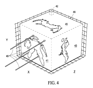
Fig. 4 is a three-dimensional radar magnitude image in the form
of a rectangular cuboid with principal projections on each face of the
rectangular cuboid.
Fig. 5 is a flow chart of an example method of generating a
representation of a surface of a target from an image volume according
to one embodiment.
Fig. 6 is an illustrative representation of a plurality of projections
through a three-dimensional complex-valued image volume according
to one embodiment.
Fig. 7 is an illustrative representation of an antenna system of a
threat detection system according to one embodiment.
Fig. 8 is an illustrative representation of a medical treatment
system according to one embodiment.
DETAILED DESCRIPTION OF THE DISCLOSURE
Some aspects of the present disclosure improve upon the state
of the art by carefully focusing radar images to preserve phase
information inherent in the propagation of the electromagnetic waves
used to form the radar images. In some implementations, wideband
microwave or millimeter-wave electromagnetic waves are used for
scanning and generating radar images. Thereafter, phase information
of reconstructed radar images may be used to determine locations of a
surface of a target since phase follows the surface of the target. In
particular, surfaces of constant phase, such as zero-phase, in the
reconstruction follow the contours of the body or target. Furthermore,
the surface of the target tracks the zero-phase contour precisely if the
image reconstruction is performed in an exacting manner as described
herein. Accordingly, surfaces of a target can be estimated by forming
a high-resolution image using backprojection or similar methods and
2
CA 03187487 2023- 1- 27
WO 2022/216291
PCT/US2021/026471
then finding the surface by numerically finding the zero-phase position
over a lattice of positions.
High-resolution active wideband microwave and millimeter-wave
imaging systems may be formed by mechanically, or electronically
scanning a transceiver over a 2D aperture. A transmitting portion of a
transceiver emits a wideband signal that interacts with the target and
is captured coherently by a receiver portion of the transceiver in one
embodiment at each point in the aperture. The subsequent data is
three-dimensional (3D) consisting of two spatial axes and one
frequency axis in the described embodiment. This data can then be
focused using backprojection or other similar methods. Resolution in
microwave imaging is limited by diffraction in the lateral dimensions and
by bandwidth in the range or depth dimension.
Conventional techniques for tracking the surface are typically
done after image formation by taking the magnitude image and forming
iso-surfaces, or surfaces of constant amplitude. However, this process
causes errors in the surface estimation since it inherently assumes that
brightness is related to position and a brighter zone in the image will
appear closer than a dimmer zone, even if they are at the same depth.
Brightness also depends on the orientation of the image target relative
to the image aperture.
Aspects of the disclosure discussed herein achieve high accuracy
by eliminating bias caused by image amplitude variations and by
exploiting the image phase. The image phase varies approximately 360
degrees for every half-wavelength in depth variation and the zero-
phase position can be estimated to accuracies of better than a few
degrees according to some embodiments disclosed herein. Therefore,
the surface of a target can be estimated to a small fraction of one-half
wavelength using inventive embodiments described herein while
conventional methods are limited by the depth resolution, which is
typically much larger than one-half wavelength.
The image reconstruction of some of the disclosed embodiments
preserves the phase and samples the image volume finely around the
target to generate a three-dimensional image volume about the target.
3
CA 03187487 2023- 1- 27
WO 2022/216291
PCT/US2021/026471
At least some of the inventive embodiments project along a line through
the image volume in a specified direction and estimate the zero-phase
position with the highest complex amplitude or magnitude along each
projection or line corresponding to the specified direction. The location
of this point closely approximates the position of the surface of the
target along each line or projection. In some embodiments, the image
volumes are used to generate representations of a surface of the target
that was scanned. In more specific embodiments, the image volumes
are each reduced to a collection of three-dimensional points, such as a
point cloud, that closely approximates the surface of the target.
In some embodiments discussed below, the surface of the target,
or a portion of the surface, can be tracked over time through an
optimization process that estimates a coordinate transformation
required to optimally align two point clouds corresponding to locations
of the surface of the object at different moments in time. A point-to-
plane iterative closest point (ICP) algorithm may be used to estimate
the coordinate transformation in some implementations described
below. However, once the point clouds are generated there are many
different options to calculate the alignment between point cloud
surfaces. For example, a surface mesh may be generated from a
surface point cloud and then used to register two surfaces in one other
illustrative example.
Referring to Fig. 1, components of an example embodiment of a
surface determination system 10 are shown. The illustrated system 10
includes an antenna system 20, control electronics 22, a transceiver
24, a data acquisition system 26, a user interface 28, and a host
computer 30. Additional arrangements of system 10 are possible
including more, less and/or alternative components.
Antenna system 20 comprises a plurality of transmitters which
are configured to emit electromagnetic energy towards a target being
scanned. The transmitters of antenna system 20 emit the
electromagnetic energy responsive to electrical signals received from
transceiver 24. Antenna system 20 further comprises a plurality of
receivers which are configured to receive electromagnetic energy
4
CA 03187487 2023- 1- 27
WO 2022/216291
PCT/US2021/026471
reflected from the target and to output electrical signals to the
transceiver 24 that correspond to the received electromagnetic energy.
Antenna system 20 may additionally include a switching network
or matrix to selectively choose different pairs of transmit and receivers
to define a plurality of sample points in space in some embodiments.
In other embodiments, the transmitters and receivers may be moved
during scanning operations including the transmitting and receiving of
electromagnetic signals. Details regarding an example configuration of
an antenna array of the antenna system 20 that may be used are shown
in Fig. 2.
Control electronics 22 are configured to control transmit and
receive operations of antenna system 20, including switching of
antennas of the transmitters and receivers therein, as well as
operations of transceiver 24 and data acquisition system 26.
Transceiver 24 is coupled with the antenna system 20 and
configured to apply electrical signals to the antenna system 20 to
generate the transmitted electromagnetic waves and to receive
electrical signals from the antenna system 20 corresponding to
received electromagnetic waves. Transceiver 24 is coherent where the
local carrier of the receiver thereof is phase locked with the carrier of
the transmitter of the transceiver 24.
The data acquisition system 26 acquires and digitizes the
transceiver output data. The data acquisition system 26 also buffers
the transceiver output data and sends it to the host computer 30.
User interface 28 includes a computer monitor configured to
depict visual images for observation by an operator, for example,
including images generated from the radar scanning and revealing
concealed contents upon an individual. User interface 28 is additionally
configured to receive and process inputs from the operator. In some
embodiments, host computer 30 uses automated threat detection
algorithms to inspect the generated imagery for threats.
Host computer 30 includes processing circuitry 29 configured to
perform or control various operations of system 10.
In one
embodiment, processing circuitry 29 is arranged to process data,
5
CA 03187487 2023- 1- 27
WO 2022/216291
PCT/US2021/026471
control data access and storage, issue commands, and control other
desired operations. Processing circuitry 29 may comprise circuitry
configured to implement desired programming provided by appropriate
computer-readable storage media in at least one embodiment. For
example, the processing circuitry 29 may be implemented as one or
more processor(s) and/or other structure configured to execute
executable instructions including, for example, software and/or
firmware instructions. Other exemplary embodiments of processing
circuitry 29 include hardware logic, GPU, PGA, FPGA, ASIC, state
machines, and/or other structures alone or in combination with one or
more processor(s). These examples of processing circuitry 29 are for
illustration and other configurations are possible.
In one embodiment, processing circuitry 29 performs waveform
signal processing and calibration and processes received radar data to
generate radar images of the target. The host computer 30 may be
implemented as a high-performance PC workstation that supports fast
image reconstruction and processing that exploits parallel processor
architecture of modern computers in one more specific embodiment.
Host computer 30 also includes storage circuitry 32 configured to
store programming such as executable code or instructions (e.g.,
software and/or firmware) used by the host computer, electronic data,
databases, radar data, image data, or other digital information and may
include computer-readable storage media. At least some embodiments
or aspects described herein may be implemented using programming
stored within one or more computer-readable storage medium of
storage circuitry 32 and configured to control appropriate processing
circuitry 29 of the host computer 30.
The computer-readable storage medium may be embodied in one
or more articles of manufacture which can contain, store, or maintain
programming, data and/or digital information for use by or in connection
with an instruction execution system including processing circuitry 29
in the exemplary embodiment. For example, exemplary computer-
readable storage media may be non-transitory and include any one of
6
CA 03187487 2023- 1- 27
WO 2022/216291
PCT/US2021/026471
physical media such as electronic, magnetic, optical, electromagnetic,
infrared or semiconductor media.
Referring to Fig. 2, an example antenna array 31 of the antenna
system 20 is shown according to one embodiment. The illustrated
antenna array 31 is a sparse array that includes a plurality of square
unit cells 33 with plural transmitters 34 along the vertical edges and
plural receivers 36 along the horizontal edges arranged in a grid. In
another embodiment, the transmitters are arranged horizontally and the
receivers are arranged vertically in a grid. Within a given unit cell 33,
all combinations of transmitters 34 and receivers 36 are selected in
pairs and used to effectively raster scan across the aperture where an
effective sample location 38 is the midpoint between the transmitter 34
and receiver 36 of a selected pair.
For a selected pair of transmitters 34 and receivers 36, the
transceiver is used to produce a swept wideband microwave or
millimeter-wave signal that is radiated by the transmitter 34 of the
selected pair. This signal interacts with the imaging target 35, such as
a human body in the illustrated example, and is reflected and received
by the transceiver through the receiver 36 of the selected pair.
In one embodiment, surface determination system 10 implements
three-dimensional radar imaging by transmitting and receiving a swept
frequency signal over a sampled two-dimensional aperture, such as the
planar aperture shown in Fig. 2. The aperture may have other shapes,
such as cylindrical, in other embodiments.
Generated raw radar data from the scanning is fully three-
dimensional with two effective aperture or spatial axes and one
frequency axis. An image reconstruction algorithm (such as
backprojection) can then be used to focus the radar data to generate a
3D image of the target 35. The sparse nature of the radar array could
allow for radiation to be delivered to a patient through the voids in the
unit cells 33, for example, as discussed below with respect to the
medical treatment system of Fig. 8.
The depth resolution is inversely proportional to the swept
frequency bandwidth and the lateral resolution is obtained by scanning
7
CA 03187487 2023- 1- 27
WO 2022/216291
PCT/US2021/026471
over the 2D aperture. In one embodiment, the swept frequency
bandwidth of a continuous wave signal is 1-100 GHz although other
microwave or millimeter ranges may be used, such as 10-40 GHz. The
processing circuitry processes the raw image data to mathematically
focus the radar data into a three-dimensional complex-valued image of
the target's reflectivity. This is commonly done with methods that use
a Fast Fourier Transform (FFT) due to its extremely high numerical
efficiency as discussed in D. Sheen, D. McMakin, and T. Hall, "Near-
field three-dimensional radar imaging techniques and applications,"
App!. Opt., AO, vol. 49, no. 19, pp. E83¨E93, Jul. 2010, the teachings
of which are incorporated herein by reference.
As mentioned above, backprojection may be used to
mathematically focus radar data. Backprojection is similar to a multi-
dimensional correlation and may be implemented using a graphical
processing unit (GPU) in one example. Additional details regarding
backprojection are discussed in D. L. Mensa, High Resolution Radar
Cross-section Imaging, Artech House, 1991, the teachings of which are
incorporated herein by reference. In addition, the formation of a three-
dimensional complex-valued image volume from raw radar data using
backprojection according to an example embodiment is discussed
below.
In this described embodiment, a generalized synthetic aperture
focusing technique for microwave and millimeter-wave imaging, also
referred to as range-domain backprojection, can be formulated as:
v(x, y, z) =11w (cti, a2)s(ct1, a2,r)e-i2kcr
Eqn. (1)
a2
where v is the complex image amplitude at location (x,y, z), s(ot1,a2,r)
is the radar range-domain phase-history from aperture location (a1, a2)
at range r, k, is the wavenumber at the center frequency, and w(cti, a2)
is a weighting function applied over the two dimensions of the aperture
to reduce side lobe levels. The range-domain radar phase history,
s(ct1,a2,r), is obtained by taking the inverse Fourier transform of the
8
CA 03187487 2023- 1- 27
WO 2022/216291
PCT/US2021/026471
radar phase history, S(a1,a2,f), and multiplying by a correction factor
ej2k1re¨j2lccr to correct the phase of the range-domain waveforms and
reduce fast phase variation to allow for accurate interpolation as shown
in Eqn. 2:
s(ai, a2, r) = {IFFT(w(f)S(al, a2, Mej2kirn e¨j2kcrnjir
Eqn. (2)
where the wavenumber at the start frequency is k1 and frequency
window function w (f) is used to control sidelobes in range. One
example window function that may be utilized is a Hamming window.
The range-domain back projection algorithm essentially
multiplies the response from each aperture location, s(a1,a2,r), with the
complex conjugate of the expected response from a scatterer at a voxel
at location (x, y, z) and range r, e12ke1 . If there is truly a scatterer at
that
voxel location, the actual response will be multiplied by its conjugate
resulting in a zero-phase or real value which when summed across the
entire aperture will all add in phase creating a large magnitude at a
point of zero-phase. Locations where there is not a scatterer will add
values with fluctuating phase that will decorrelate and the magnitude
will tend to zero.
Referring to Fig. 3, an illustrative representation of scanning a
target (not shown) and use of a range-domain back projection algorithm
is shown. Radar transmitters 34 and receivers 36 are scanned either
electronically as discussed above, or alternatively mechanically, over a
typically planar or cylindrical aperture 40, to implement scanning of an
image voxel space 44 about the target to be scanned. The 3D radar
phase history, two spatial axes and a frequency axis, can be used to
focus and generate a radar image in the form of a 3D complex-valued
image volume. The image volume includes a plurality of voxels 42 each
having an associated complex value that includes an amplitude and
phase. In Fig. 3, a selected pair including transmitter 34 and a receiver
36 located at positions T, R emit and receive electromagnetic energy
with respect to an illustrative voxel 42 and a plurality of ranges between
the transmitter 34 and receiver 36 and voxel 42 are shown as well as
9
CA 03187487 2023- 1- 27
WO 2022/216291
PCT/US2021/026471
the ranges of the transmitter 34 and receiver 36 with respect to the
origin.
The above-described range-domain backprojection is used in one
embodiment to focus the radar-phase history data into a 3D complex-
valued image volume, an example of which is shown in Fig. 4 as a result
of scanning a human target.
The depicted image volume 46 is in the form of a rectangular
cuboid that corresponds to the image voxel space 44 in the illustrated
embodiment and includes a plurality of complex-valued voxels 42
defined by the X, Y, Z axes or dimensions. Fig. 4 depicts a radar
magnitude image of a human target with the principal projections on
faces 41, 43, 45 corresponding to the front, top and right side of the
rectangular cuboid, respectively. The voxel 42 shown in Fig. 4 is
illustrative and larger than actual voxels of the image volume (i.e., a
generated image volume includes many more voxels than the
illustrative example shown in Fig. 4).
For each X and Y image location in surface 48, the processing
circuitry projects 49 through the Z (e.g., depth) direction to find the
voxels having increased complex amplitude values along the projection
as discussed further below with respect to Fig. 6. Each projection 49
is a straight line perpendicular to face 41 of the image volume 46. A
given projection 49 through an image volume identifies all Z values of
the image volume in the depth direction that correspond to a given X-Y
image location. As discussed further below, one of the voxel values in
the depth direction of a projection 49 is interpolated to identify a point
of a surface of a target being scanned that corresponds to the given X-
Y location.
As discussed above, the actual response at a given voxel location
will be multiplied by its complex conjugate resulting in a real value
which when summed across the entire aperture will all add in phase
creating a large magnitude at a point of zero-phase in the presence of
a scatterer at the given voxel location and locations where there is not
a scatterer will add values with fluctuating phase that will decorrelate
and the magnitude will tend to zero. This implies that a surface of a
CA 03187487 2023- 1- 27
WO 2022/216291
PCT/US2021/026471
target will be at a location near the maximum image amplitude at the
zero-phase location of the complex voxel amplitude. By projecting
through the complex-valued image volume and finding the zero-phase
location under the maximum complex amplitude envelope along the
projection 49, a point cloud or other representation of the target surface
can be generated that is largely independent of image amplitude
variations.
In some embodiments discussed below, the amplitude of the
complex-valued image only affects which points are valid surface points
based on a chosen amplitude or magnitude threshold. For the case
where the Z direction is depth, a point for each X, Y image location in
the complex volume 46 may be used to generate a point cloud for the
image volume if the point has an amplitude above the threshold as
discussed further below.
Referring to Fig. 5, a flow chart of an example method of
processing one or more radar images of a target to determine a plurality
of points, for example of one or more point clouds, that correspond to
locations of a surface of the target in space when the one or more radar
images where generated. As discussed below, amplitude and phase
information of complex values of the radar image in the form of a three-
dimensional complex-valued image volume are used to generate a
representation of the surface of the target, such as a point cloud. The
illustrated method may be executed using processing circuitry of the
host computer described above in one embodiment. Other methods
are possible including more, less and alternative acts.
At an act A10, data of a previously generated three-dimensional
complex image volume is accessed. The image volume may have been
generated using backprojection and be in the shape of a rectangular
cuboid according to the example embodiment discussed above. The
accessed data of the image volume includes complex values of
amplitude information and phase information for each of the voxels
within volume.
At an act Al2, a plurality of image locations of the image volume
are defined. Two spatial dimensions or axes (e.g., X and Y) of the
11
CA 03187487 2023- 1- 27
WO 2022/216291
PCT/US2021/026471
accessed image volume are utilized to define the image locations in the
described example.
At an act A13, a plurality of voxels are identified along a third
dimension (e.g., Z) for each of the X, Y image locations. A straight line
projection that is perpendicular to the X, Y face of the rectangular
cuboid is made through the image volume in the Z (depth) dimension
of the image volume for each of the defined X, Y image locations to
identify a plurality of voxel locations in the Z dimension of the image
volume that correspond to the respective X, Y image location. For a
given X, Y location, a complex amplitude value and phase value for
each voxel location corresponding to the given X, Y location in the
depth direction of the image volume is retrieved.
At an A14, the retrieved voxels of the projection in the depth
direction are processed to identify voxels in each projection which have
increased complex amplitudes compared with other voxels of the
respective projection and the selected voxels may be used to define a
maximum complex amplitude envelope for the given projection. The
voxel for each projection having an increased complex amplitude
compared with other voxels of the same projection is selected as a
result of the processing in act A14. In a more specific embodiment, a
voxel having the maximum complex amplitude is selected for each
projection.
At an act A16, the complex amplitude of the voxel of a projection
for a given X, Y image location having the maximum complex amplitude
and selected using act A14 is compared with a threshold.
The voxels of the projection are disregarded and not utilized with
respect to surface determination of the target if the selected voxel
having the maximum complex amplitude does not exceed the threshold
(and is therefore deemed to not correspond to the surface of the target).
Thereafter, the method returns to act A13 to process voxel values of
another projection through the image.
The method proceeds to an act A18 if the complex amplitude of
the voxel processed in act Al 6 exceeds the threshold. The voxel values
under the maximum complex amplitude envelope are interpolated at act
12
CA 03187487 2023- 1- 27
WO 2022/216291
PCT/US2021/026471
A18 using phase information of the voxel values to identify an
interpolated value that corresponds to the surface of the target. For
example, as discussed below with respect to Fig. 6, the interpolated
value may correspond a location in the Z dimension direction that has
a given phase value, such as zero-phase, and is closest to a voxel
location having a maximum complex amplitude for the projection. The
use of interpolation increases the resolution of the surface
determination of the target in the third dimension compared with use of
the voxel having the maximum complex amplitude without interpolation
since the interpolated value having to the given phase value and
identified as corresponding to the surface of the target is often between
the locations of two adjacent voxels in the projection. Accordingly, the
interpolated locations corresponding to the given phase value more
accurately correspond to the actual locations of the surface of the target
compared with locations of the voxels having the increased complex
amplitude.
At an act A20, the location (i.e., depth) resulting from the
interpolation for the given projection is utilized to generate a
representation, such as a point cloud, of the surface of the target.
Thereafter, the method returns to act A13 to process voxel values of
another projection. Using the above-described example process, only
voxels having complex amplitudes greater than the threshold are used
to generate the representation of the surface of the target.
Referring to Fig. 6, four successive projections 50-53 through the
complex image volume moving horizontally are graphically shown for
four different respective X-Y image locations of an image volume. Each
value depicted has been normalized to unit amplitude.
Line 54 in each projection corresponds to the complex magnitude
or amplitude of the image volume at each voxel 56 (sample point) for
the respective projection. Line 57 in each projection is the real part of
the complex image for the respective projection, and line 58 in each
projection is the imaginary part of the complex image for the respective
projection.
13
CA 03187487 2023- 1- 27
WO 2022/216291
PCT/US2021/026471
The vertical line 59 of each projection is the voxel location of the
maximum complex amplitude along the respective projection.
The vertical line 60 of each projection is a location that results
from interpolation using phase information of the image volume. In one
embodiment, phase information of the voxels is used to identify an
interpolated location in the third dimension for each of the X-Y locations
that corresponds to a surface of the target and that is different than the
locations of the voxels. In one embodiment, a given phase value of
zero-phase is used to identify the interpolated locations in the third
dimension for each of the X-Y image locations. In one embodiment, the
interpolated location in the third dimension for a given X-Y image
location is a zero-phase location closest to the voxel having the
maximum complex amplitude for the given X-Y location. In particular,
line 60 for each projection is the zero-phase location that is closest or
nearest to the maximum complex amplitude of line 59 and is selected
as a location or point corresponding to a surface of the target being
imaged for the depth direction for that respective X-Y location and
projection. Accordingly, the interpolated location for the given X-Y
location is selected to be the zero-phase position closest to the
maximum complex amplitude. As mentioned above, X-Y locations that
do not have a complex amplitude above the given threshold are
identified as not corresponding to the surface of the target. In addition,
it is also possible that the zero-phase location of a given projection may
also correspond exactly to the maximum amplitude location of the
projection and be used to generate a representation of a surface of a
target.
In some embodiments, the interpolated locations (i.e., depths) for
the X-Y image locations may be used by the processing circuitry to
generate a representation of the surface of the target. For example,
the representation of the surface of the target may be a point cloud
although other embodiments are possible.
In some arrangements, the phase value of interest utilized during
the interpolation may be a value other than zero and utilized to identify
the locations of the surface of the target for the different X-Y image
14
CA 03187487 2023- 1- 27
WO 2022/216291
PCT/US2021/026471
locations. For example, other or different image reconstruction
techniques and/or different processing of the radar data may be utilized
to generate an image volume in other embodiments and may result in
a different constant phase value (apart from zero) that corresponds to
a surface of the target and may be used during the interpolation
operations described above to locate points for inclusion in the point
cloud or other representation of the surface of the target being scanned.
Processing of the original complex-valued three-dimensional
radar image enables the generation of a smooth and accurate point
cloud representation of the surface of an imaged target by proper
exploitation of the phase information as discussed above. Use of phase
information of the image allows decoupling of the magnitude of the
image from the geometry of the target thereby allowing the surface of
the target to be determined with increased accuracy compared with
arrangements that solely rely upon use of magnitude information to
determine the surface of the target.
In particular, as shown in the projections of Fig. 6, the determined
zero-phase locations vary in a smooth predictable way as the projection
moves along different lines in the 3D volume compared with maximum
amplitude locations that are more erratic.
Pseudocode of an example zero-phase surface estimation
algorithm that is configured to select the zero-phase crossing near the
maximum amplitude as the location of the surface of a target for
inclusion as a point in a point cloud for a respective X-Y location is
shown below:
for i in range(nx):
for j in rande(ny):
zniõ = argmax (abs(v[i, j, z]))
maxV alue = abs(v[i, j, zmax])
if maxValue > threshold:
= interpolate the complex amplitude, v[i,j], around zn,õ
to find the closest point where ang le(v[i, j , = 0
PointCloud[ti,j] =
CA 03187487 2023- 1- 27
WO 2022/216291
PCT/US2021/026471
As discussed above, locations of zero-phase in the depth
direction of a generated 3D image volume may be utilized to locate a
surface of a target since the zero-phase information is largely
independent of image amplitude variations.
Ideally a surface
estimation of a target should be independent of the object's orientation,
however, the amplitude response of an object in a microwave or
millimeter-wave radar image is dependent not only on the target's
geometry, but also on its orientation relative to the radar array. An
advantage of using a point cloud based on the zero-phase location
compared with use of amplitude information only of 30 images is that
the geometry of the objects in the image is decoupled from the image
amplitude.
A wide variety of new applications and processing techniques are
enabled once a representation, such as a point cloud, has been
generated from the surface of a target. For example, point clouds may
be generated for use in threat detection, such as monitoring for
weapons or contraband in screening of persons at a public venue, such
as an airport, stadium event, etc. A point cloud derived surface of a
person shows more information than an intensity projection image and
includes information about the geometry of the target image that does
not depend on the image intensity or orientation of the target relative
to the antenna array. This provides more information for anomaly
detection, such as contraband or weapons concealed beneath clothing
of an individual.
Referring to Fig. 7, an antenna system of a threat detection
system including a plurality of antenna array columns 70 are shown in
a 2D scanner configuration according to one embodiment. The
example threat detection system may be implemented in a walk-by
imaging application, for example to scan for concealed threats or
contraband upon clothed individuals entering a screened area. The
columns 70 are arranged opposite to one another and positioned to
scan opposite sides of a target 35 moving on a path 72 between
columns 70. The columns are configured to emit electromagnetic
energy towards target 35 moving on path and receive electromagnetic
16
CA 03187487 2023- 1- 27
WO 2022/216291
PCT/US2021/026471
energy reflected from the individual. Electromagnetic energy of
millimeter wave or microwave frequencies may be utilized for the
scanning and which enable scanning of the individual to reveal threats
or contraband concealed by the individual's clothing.
Each column 70 includes a linear antenna array 71 that includes
both transmit and receive antennas (not shown in Fig. 7) in one
embodiment.
The linear antenna array 71 in each column 70 is
mechanically moved 73 next to the target 35 during scanning of the
target 35. A length of the linear antenna array 71 is one spatial
dimension of the aperture and movement 73 of the linear array 71 is a
second spatial dimension of the aperture. Real-time, high-speed data
collection and scanning is used in one embodiment to effectively freeze
the motion of the target 35 during a data frame from each column 70
and to allow fine sampling of the target 70 passing through the system.
In another embodiment, the columns 70 each include a 2D
antenna array such as shown in Fig. 2 that electronically scans a two-
dimensional aperture to freeze motion.
Numerous transmit locations may be provided along the length of
the column 70 for angularly diverse illumination of the target 35. In one
embodiment, the sequentially switched linear array scans one
dimension of the imaging aperture electronically at high speed and is
accomplished by sequencing through each transmit and receive pair of
antennas using microwave-or millimeter-wave switching networks
connected to the radar transceiver. Data is continuously collected as
the target 35 moves adjacent to or through the scanning system.
In one embodiment, a sparse array technique is utilized which
achieves required sampling density with a reasonable number of
antennas by using multiple combinations of transmit and receive
antennas to increase the density of aperture samples while reducing
the number of antenna elements. Details regarding suitable antenna
arrays including sparse arrays are described in US Patent No.
8,937,570 and Sheen, DM, "Sparse Multi-Static Arrays for Near-Field
Millimeter-Wave Imaging," In 2013 IEEE Global Conference on Signal
and Information Processing, GlobalSIP, IEEE Computer Society, pp.
17
CA 03187487 2023- 1- 27
WO 2022/216291
PCT/US2021/026471
699-702, 2013, the teachings of which are incorporated herein by
reference.
The threat detection system may include additional components
such as shown in Fig. 1 to implement scanning operations of an
individual as well as processing of radar data to generate image
volumes and processing of the image volumes to determine points of a
surface of the target 35. In one embodiment, the processing circuitry
uses the received electromagnetic energy to generate a three-
dimensional complex-valued image volume of at least part of the
clothed individual. The processing circuitry is further configured to
process amplitude information and phase information of the complex
values to generate a representation, such as a point cloud, of a surface
of the target 35 to provide information regarding a surface anomaly
beneath clothing of the clothed individual. In one embodiment, the
processing circuitry may control the user interface to display a graphical
image of the point cloud corresponding to the surface of the target 44.
Based on an accurate surface representation of an imaged object
or person it is possible to look at how the surface changes spatially
using gradients. Unnatural or sharp changes might indicate a threat that
could be detect. For example, a manmade object should have easily
identifiable characteristics that are distinct from the natural shape of
the body.
In addition, it is possible to register point-clouds between radar
images generated from scans of a target at different moments in time
to provide information regarding movement of the surface of the target
between the moments in time when the radar images were captured.
An accurate surface allows matching of objects based on their
geometry independent of the image amplitude.
Different methods may be used to register two different point
clouds, for example, including use of an Iterative Closest Point
algorithm (ICP), or generating a surface mesh and aligning surfaces as
discussed in S. Rusinkiewicz and M. Levoy, "Efficient variants of the
ICP algorithm," in Proceedings Third International Conference on 3-D
Digital Imaging and Modeling, May 2001, pp. 145-152, and M. A.
18
CA 03187487 2023- 1- 27
WO 2022/216291
PCT/US2021/026471
Audette, F. P. Ferrie, and T. M. Peters, "An algorithmic overview of
surface registration techniques for medical imaging," Medical Image
Analysis, vol. 4, no. 3, pp. 201-217, Sep. 2000, the teachings of which
are incorporated herein by reference. In another embodiment, a variant
of the ICP algorithm referred to as point-to-plane ICP algorithm from
the Open3D python library may be used as discussed in Q.Y. Zhou, J.
Park, and V. Koltun, "Open3D: A Modern Library for 3D Data
Processing," arXiv, 2018, the teachings of which are incorporated
herein by reference.
The general ICP algorithm iteratively minimizes an objective
function, f, by updating a transformation matrix, T, to align two point
clouds as discussed in P. J. Bes1 and N. D. McKay, "A method for
registration of 3-D shapes," presented at the IEEE Transactions on
Pattern Analysis and Machine Intelligence, Feb. 1992, and Y. Chen and
G. Medioni, "Object modeling by registration of multiple range images,"
in Proceedings of the IEEE International conference on Robotics and
Automation (ICRA), (Sacramento, CA, USA), pp. 2724- 2729, Apr.
1991, the teachings of which are incorporated herein by reference. This
objective function is the minimization of the distance between points in
a correspondence set, (p, q) e K, between a source point cloud, q e Q,
and a target point cloud, p E P. The point-to-plane ICP variation's
objective function utilizes an estimated surface normal, np, to penalize
corresponding points that are tangential to the estimated surface as
discussed in the Chen reference incorporated by reference above. The
objective function to be minimized is formulated as shown in Equation
3:
Eqn. (3)
f(T) = ((p ¨ T q) = np)2
(p,q)EIC
This method does not assume there is a 1:1 correspondence
between all points in the two-point clouds. It only minimizes the error
between points that are determined to have correspondence that are
useful in some embodiments because based on the orientation of an
object when it is imaged there could be shadowing of the surface
19
CA 03187487 2023- 1- 27
WO 2022/216291
PCT/US2021/026471
creating "holes" in the point cloud that may not be there when the object
is in a different orientation. The point-to-plane ICP algorithm was found
to provide millimeter and sub-millimeter level registration accuracy
during simulated and experimental test cases.
In some embodiments, a rigid transformation between two-point
clouds is assumed, although non-rigid registration methods that do not
make this assumption may be used as discussed in L. Liang et al.,
"Nonrigid iterative closest points for registration of 3D biomedical
surfaces," Optics and Lasers in Engineering, vol. 100, pp. 141-154,
Jan. 2018, the teachings of which are incorporated herein by reference.
The algorithm outputs a transformation matrix that is indicative of
movement of the surface of the target between the different radar
images in six degrees of freedom including three corresponding to
rotational movement and three corresponding to translation movement.
The determined movement or motion of the surface may be used in
different applications including monitoring movement of a target surface
(i.e., skin of a patient) for use in medical implementations in one
illustrative example.
Referring to Fig. 8, a medical treatment system 100 is shown
according to one embodiment. The illustrated system 100 is configured
to deliver a therapeutic treatment 104, such as radiation or ultrasound
pulses, to a patient 102 undergoing medical treatment. The
determination of surfaces as described above may be used to control
the delivery of the therapeutic treatment 104 to a specific desired target
location 106 of the skin of the patient 102 during the delivery of
therapeutic treatment 104.
In one example, the determined motion from surfaces of the
patient 102 may be used to confirm body position and accurately track
body human motion over time during radiation therapy for radiation
oncology applications. Accurately tracking of the surface of the patient
102 is desired for radiation oncology applications as the radiation
should be applied carefully to minimize exposure of and collateral
damage to healthy tissue. The accurate tracking of respiratory motion
CA 03187487 2023- 1- 27
WO 2022/216291
PCT/US2021/026471
is particularly important during radiation therapy as tumors in the lower
chest and upper abdomen move as the patient breathes.
Real-time radar imaging of the surface of the patient's skin may
be used to monitor motion of the patient 102 during treatment and
indicate the most likely position of the target location 106 of the patient
102. High resolution 3D volumetric imaging techniques described
herein may be used to provide real time information about not only the
respiratory cycle of the patient 102 but also their body's absolute
position in space that will allow for real time updates of the position of
the patient 102 increasing the effectiveness of the radiation therapy and
delivery of the therapeutic treatment 104 to the desired target location
106.
Millimeter-wave (MMW) imaging described herein according to
some embodiments of the disclosure is well-suited for tracking body
surface as it "sees through" optically opaque clothing. Accordingly,
some patients 102 may remain fully-clothed and blanketed while
receiving treatment 104 and may reduce the degree of external restraint
needed to ensure correct dose delivery.
An antenna system 108 that is incorporated into the medical
treatment system 100 is shown in Fig. 8. The antenna system 108
comprises a plurality of transmitters and receivers and different pairs
of the transmitters and receivers may be selected during scanning
operations as described above with respect to Fig. 2. Antenna system
108 emits electromagnetic energy towards patient 102 and receives
electromagnetic energy reflected from patient 102. As shown in the
illustrated example embodiment, a beam of therapeutic treatment 104
passes through the antenna system 108 before reaching the patient
102.
The medical treatment system 100 may include additional
components such as those shown in Fig. 1 to implement scanning
operations of the patient 102 as well as processing of radar data to
generate image volumes at different moments in time and processing
of the image volumes to determine points of a surface corresponding to
the skin of the patient 102. The electromagnetic energy reflected from
21
CA 03187487 2023- 1- 27
WO 2022/216291
PCT/US2021/026471
patient 102 and received by the antenna system 108 may be processed
to generate three-dimensional complex-valued image volumes of the
patient 102 at different moments in time in accordance with the above-
described aspects of the disclosure.
The processing circuitry is further configured to process
amplitude information and phase information of the complex values of
each of the three-dimensional complex-valued image volumes to
generate a plurality of representations, such as point clouds, of the skin
of the patient 102 for use to identify a plurality of locations of the target
106 of the patient 102 at the different moments in time. The processing
circuitry is configured to use the locations of the target 106 of the
patient 102 to control a therapeutic delivery system 110 to direct the
therapeutic treatment 104 to the target 106 of the patient 102 at
different moments in time of the treatment.
The generated radar images are processed to identify the surface
corresponding the skin of the patient 102 at different moments in time
when the radar images were generated and the identified surfaces may
be used to provide information regarding movement of target location
106 of patient 102 during treatment, for example as discussed above,
by registration of point clouds including the target location 106.
Based on radar image derived point cloud data, a patient's
breathing cycle can be monitored and the treatment 104 is turned on
and off to optimally match the patient's breathing cycle to reduce
exposure of healthy tissue to the treatment. In addition, the system 110
can be moved to optimally align with the target location 106 of the
patient as their position in space is updated based on the radar image
point cloud.
The determined information regarding movement of the patient
102 may be utilized by the medical treatment system 100 to adjust or
update the location of where the therapeutic treatment 104 is directed
to account for movement of the patient and to attempt to direct the
treatment 104 to the target location 106 after movement of the patient
102. The example system 100 of Fig. 8 includes a platform 112 that
supports the patient 102 during treatment, a first positioning system
22
CA 03187487 2023- 1- 27
WO 2022/216291
PCT/US2021/026471
114 and a second positioning system 116. The first positioning system
114 includes one or more motors (not shown) that are configured to
move therapeutic delivery system 110 such that a beam of the
therapeutic treatment 104 is directed to the target location 106.
Accordingly, control of the positioning system 114 enables the direction
of the therapeutic treatment 104 to be adjusted during treatment of the
patient 102. In addition, the second positioning system 116 includes
one or more motors (not shown) that are configured to move platform
112 and patient 102 thereon, and control of the positioning system 116
enables the position of the platform 112 and patient 102 to be adjusted
during treatment of the patient 102.
The determined movement of the patient 102 using the radar
images discussed above may be used by a microprocessor or other
control circuitry to control one or more motors of the positioning
systems 114, 116 to direct the therapeutic treatment 104 to the target
location 106 of patient 102 as the patient 102 and target location 106
thereof move during treatment and to minimize exposure of other
locations of the patient to the therapeutic treatment 104.
As described above, some embodiments of the disclosure utilize
phase information in addition to complex amplitude information of a
three-dimensional complex-valued image to generate a representation,
such as a point cloud, of a surface of a target. The utilization of phase
information has increased accuracy with respect to determining the
positioning of the surface of the target in space and movement of the
surface of the target compared with arrangements that register voxels
of different images solely based upon amplitude or intensity that do not
necessarily register geometric features of the target between images.
Some conventional methods generate surfaces of constant image
amplitude without use of phase information which creates substantial
errors since the amplitude of these images can vary greatly depending
on many factors independent of the target's surface position.
Aspects of the disclosure provide improvements in medical
treatment applications, such as radiation oncology applications, since
radar images of the patient may be generated through clothing of the
23
CA 03187487 2023- 1- 27
WO 2022/216291
PCT/US2021/026471
patient while some existing systems use optical cameras that cannot
adequately handle obscurations such as patient clothing, blankets, or
constrainment masks, or these systems use fiducial markers on the skin
of the patient. As oncology patients are frequently anemic and
hypersensitive to cold temperatures, even a partial disrobing can be
very uncomfortable. In addition, some conventional systems use
respiratory gating that generally just turns the beam off and on as the
lesion or other target moves out of, and back into, the treatment field
without redirection of the beam during even a portion of the respiratory
cycle of the patient. Some of the systems and method disclosed herein
allow a patient to remain fully-clothed and blanketed while receiving
radiation therapy and which may also reduce the degree of external
restraint needed to ensure correct dose delivery.
In compliance with the statute, the invention has been described
in language more or less specific as to structural and methodical
features. It is to be understood, however, that the invention is not
limited to the specific features shown and described, since the means
herein disclosed comprise preferred forms of putting the invention into
effect. The invention is, therefore, claimed in any of its forms or
modifications within the proper scope of the appended aspects
appropriately interpreted in accordance with the doctrine of
equivalents.
Further, aspects herein have been presented for guidance in
construction and/or operation of illustrative embodiments of the
disclosure. Applicant(s) hereof consider these described illustrative
embodiments to also include, disclose and describe further inventive
aspects in addition to those explicitly disclosed. For example, the
additional inventive aspects may include less, more and/or alternative
features than those described in the illustrative embodiments. In more
specific examples, Applicants consider the disclosure to include,
disclose and describe methods which include less, more and/or
alternative steps than those methods explicitly disclosed as well as
apparatus which includes less, more and/or alternative structure than
the explicitly disclosed structure.
24
CA 03187487 2023- 1- 27