Note: Descriptions are shown in the official language in which they were submitted.
WO 2022/020941
PCT/CA2021/051024
TITLE OF THE INVENTION
AN ELECTRO-MECHANICAL CROSS STEER DRIVE DEVICE
FOR A VEHICLE
COPYRIGHT NOTICE
This patent document contains material which is subject to copyright
protection.
The copyright owner has no objection to the facsimile reproduction by anyone
of
this patent document as it appears in the Patent and Trademark Office patent
file
or records, but otherwise reserves all copyright rights whatsoever.
FIELD OF THE INVENTION
The invention relates to the field of drive devices useful as a
vehicle propulsion system and in particular, a electro-mechanical drive device
suitable for use in a wheeled or track laying vehicle supplying main
propulsion and
steering functions.
BACKGROUND OF THE INVENTION
A drive device suitable for use in a wheeled or track laying vehicle supplying
main
propulsion and steering functions is provided. Typically, a track laying
vehicle will
have a left-hand and right-hand track which can be driven at the same speed
for
straight-line movement or one track driven slower relative to the other for
steering
or pivot turning of the vehicle.
Referring to Fig. 1, the prior art shows separate electric motors/mechanical
transmission drive systems being used in a track laying vehicle, with one
electric
motor/mechanical transmission per track. By varying the speed/torque of each
motor, the vehicle can be propelled in a straight line or steered. If a
component
1
CA 03187550 2023- 1- 27
WO 2022/020941
PCT/CA2021/051024
in one drive breaks, only one track on the intact side can be driven to
continue
vehicle movement. In addition, steering becomes inefficient as the inside
track
must often be slowed down (power absorbed) to enable steering; either the
inside
track must have a brake to slow it sufficiently (very inefficient) or the
inside track's
motor becomes a generator (more efficient than a brake but losses occur
turning
mechanical power into electrical power, through the power control unit, then
back
into mechanical power at the outside track's motor).
An alternative drive device as provided by US 2005/0187067 and as shown in
Fig.
2, is to use a gear assembly with one motor providing linear traction and a
second
motor providing steering overlaying power on the left- and right-hand outputs
through a pair of summing planetary differentials. The advantage of this
device is
steering can be very efficient since power can be absorbed from the inside
track
and transferred to the outside track. However, the disadvantage is that a
separate
motor and gearing system is required for steering and the steering motor
cannot
be used for linear traction and the linear traction motor cannot be used for
steering.
The invention presented here solves the problem of choosing between a system
which has the added weight of a separate steering system versus a less
efficient
system which uses a dual independent motor drive.
Other objects of the invention will be apparent from the description that
follows.
SUMMARY OF THE INVENTION
According to the present invention there is provided an electro-mechanical
cross-
steer device for a vehicle. The device may include a first and a second motor
and
first and second output planetary gear set, each having a transfer gear
assembly
mechanically connected to the first and second motors, respectively.
Additionally,
a differential may be included which is mechanically connected to the first
and
second output planetary gear sets via a mainshaft connected to the first and
2
CA 03187550 2023- 1- 27
WO 2022/020941
PCT/CA2021/051024
second output planetary gear sets. First and second input shafts may be
mechanically connected to the first and second transfer gear assemblies and to
the differential. First and second output shafts may be respectively connected
to
the first and second output planetary gear sets with each of the output shafts
operable to drive a particular side of a vehicle. When conditioning speeds of
the
first and second motors to equal values, speed ratios between the first and
second
output shafts may be 1:1 and the vehicle may move in a straight line. When
conditioning the speeds of the first and second motors to unequal values, the
speed ratios between the first and second output shafts may not be 1:1 and
braking
energy from an output shaft may be transferred to the other output shaft
thereby
allowing steering of the vehicle without braking energy being dissipated as
heat.
According to the present invention, there is also provided a method for
electro-
mechanically cross-steering a vehicle. The method may provide a first and a
second motor and first and second output planetary gear set, each having a
transfer gear assembly mechanically connected to the first and second motors,
respectively. Additionally, a differential may be provided which is
mechanically
connected to the first and second output planetary gear sets via a mainshaft
connected to the first and second output planetary gear sets. First and second
input shafts may be provided that are mechanically connected to the first and
second transfer gear assemblies and to the differential. First and second
output
shafts may be respectively provided and connected to the first and second
output
planetary gear sets with each of the output shafts operable to drive a
particular
side of a vehicle. When conditioning speeds of the first and second motors to
equal values, speed ratios between the first and second output shafts may be
1:1
and the vehicle may move in a straight line. When conditioning the speeds of
the
first and second motors to unequal values, the speed ratios between the first
and
second output shafts may not be 1:1 and braking energy from an output shaft
may
be transferred to the other output shaft thereby allowing steering of the
vehicle
without braking energy being dissipated as heat.
3
CA 03187550 2023- 1- 27
WO 2022/020941
PCT/CA2021/051024
Other aspects of the invention will be appreciated by reference to the
detailed
description of the preferred embodiment and to the claims that follow.
BRIEF DESCRIPTION OF THE DRAWINGS
The preferred embodiment of the invention will be described by reference to
the
drawings thereof in which:
Fig. 1 is PRIOR ART schematic of 2 separate electric motors/mechanical
transmission drive systems;
Fig. 2 is PRIOR ART schematic of an alternative gear assembly with one motor
providing linear traction and a second motor providing steering;
Fig. 3 is a schematic of a single mode electro-mechanical cross-steer drive
device
of the present invention;
Fig. 4. is a schematic of a components of a center differential of Fig. 3;
Fig. 5 is partial cross section of the center differential of Fig. 3;
Fig. 6 is a schematic of a left hand (LH) output planetary of Fig. 3;
Fig. 7 is a schematic of a right hand (RH) output planetary of Fig. 3;
Fig. 8 is a schematic of a single mode / single range electro-mechanical cross-
steer drive device with motors coaxial with output shafts of the present
invention;
Fig. 9 is a schematic of a dual mode / two range electro-mechanical cross-
steer
drive device of the present invention;
4
CA 03187550 2023- 1- 27
WO 2022/020941
PCT/CA2021/051024
Fig. 10 is a schematic of a dual mode / three range electro-mechanical cross-
steer
drive device of the present invention;
Fig. 11 is a schematic with a LH/RH motor coupling clutch and a differential
brake
added to the present invention;
Fig. 12 is a schematic with LH/RH motor coupling clutch active of the present
invention;
Fig. 13 is a schematic of the preferred embodiment of the present invention;
Fig. 14 is a schematic of 1st range components driving/steering in the
[referred
embodiment of the present invention;
Fig. 15 is a schematic of 2nd range components driving/steering in the
preferred
embodiment of the present invention; and
Fig. 16 is a schematic of 3rd range components driving/steering in the
preferred
embodiment of the present invention.
DESCRIPTION OF THE PREFERRED EMBODIMENT
OF THE INVENTION
Table of Components
Name
1 DRIVE DEVICE
2 LH MOTOR
3 RH MOTOR
4 LH OUTPUT SHAFT
5 RH OUTPUT SHAFT
6 ELECTRICAL POWER CONNECTOR
5
CA 03187550 2023- 1- 27
WO 2022/020941
PCT/CA2021/051024
7 ELECTRICAL POWER CONNECTOR
9 FIRST BRAKE
SECOND BRAKE
11 CLUTCH
12 MAINSHAFT
19 DRIVE HOUSING (full housing not shown)
LH TRANSFER GEAR ASSEMBLY
RH TRANSFER GEAR ASSEMBLY
LH OUTPUT PLANETARY
RH OUTPUT PLANETARY
2nd RANGE GEARSET
80 LH/RH MOTOR COUPLING CLUTCH
100 CENTER DIFFERENTIAL
101 LH INPUT SHAFT
102 RH INPUT SHAFT
103 CENTER DIFFERENTIAL OUTPUT SHAFT
105 LH SUN GEAR
106 RH SUN GEAR
107 CARRIER
109a, b... LH COMPOUND PLANET GEAR
110a, b... RH COMPOUND PLANET GEAR
170 DIFFERENTIAL BRAKE
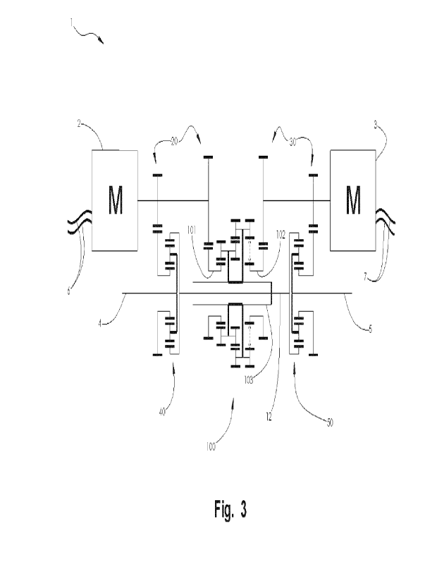
Referring to Figs. 3 to 5, the drive device 1 includes left hand (LH) 2 and
right hand
(RH) 3 motors, respectively. A center differential 100 is provided with a LH
input
5 shaft 101, a RH input shaft 102 and center differential output shaft
103.
Additionally, LH transfer gear assembly 20 and RH transfer gear assembly 30
are
also provided. Furthermore, LH output planetary gear set 40 and RH output
planetary gear set 50 are provided with each gear set having at least 3
6
CA 03187550 2023- 1- 27
WO 2022/020941
PCT/CA2021/051024
components. The device 1 also includes a mainshaft 12, LH output shaft 4 and
RH output shaft 5. A housing 19 supports the above components.
Additional details of LH and RH output planetary gear sets 40 and 50 are shown
in Figs. 6 and 7.
LH motor 2 is mechanically connected to a first component of the LH output
planetary gear set 40 with LH transfer gear assembly 20. In the preferred
embodiment, the first component of the LH output planetary gear set 40 is a
sun
gear 41. In a similar manner, RH motor 3 is mechanically connected to a first
component of the RH output planetary gear set 50 with RH transfer gear
assembly
30. In the preferred embodiment, the first component of the RH output
planetary
gear set 50 is a sun gear 51.
LH and RH motors 2 and 3 are also connected to the LH and RH input shafts 101
and 102 respectively of center differential 100 with LH and RH transfer gear
assemblies 20 and 30.
The center differential 100 is connected to a second component of the LH
output
planetary gear set 40 with mainshaft 12 and to a second component of the RH
output planetary gear set 50 also with mainshaft 12. In the preferred
embodiment,
the second components of the LH and RH output planetary gear sets 40 and 50
are ring gears 42 and 52 respectively.
A third component of the LH output planetary gear set 40 is connected to the
LH
output shaft 4. A third component of the RH output planetary gear set 50 is
connected to the RH Output Shaft 5. In the preferred embodiment, the third
components of the LH and RH output planetary gear sets 40 and 50 are carrier
assemblies 43 and 53 respectively.
7
CA 03187550 2023- 1- 27
WO 2022/020941
PCT/CA2021/051024
In an alternate embodiment shown in Fig. 8, the LH and RH 2a and 2b motors are
located coaxially with the LH and RH output shafts 4 and 5 and are directly
connected to the output planetary gear sets 40 and 50. The motors 2a and 2h of
the alternate embodiment are constructed in a manner to allow the LH and RH
output shafts 4 and 5 to pass freely through the rotational axes of the
motors.
In yet another alternate embodiment (not shown) the first second and third
components of the LH and RH output planetary gear sets 40 and 50 could be any
of the suns, rings or carriers of the LH and RH Output Planetary Gear Sets 40
and
50.
By conditioning the speeds of the motors to equal values, the speed ratios
between
left hand and right-hand outputs of the drive unit are both 1:1 and the
vehicle
moves in a straight line; torques are adjusted as required to maintain
straight line
operation.
By conditioning the speeds of the motors to unequal values, steering
capability is
enabled; torques are adjusted and may be negative (braking) at one output
while
positive (driving) at the other output. The steering is said to be
regenerative since
braking energy is transferred from the braking side to the driving side rather
than
being dissipated as heat through a conventional brake-steer system.
The mode described here is known as Cross Steer Mode meaning that mechanical
power from the LH and RH Motors 2 and 3 interact before arriving at the LH and
RH output shafts 4 and 5.
In a further alternative embodiment, the LH and RH motors are variable
displacement hydraulic motors accepting fluid pressure and flow from one or
more
hydraulic pumps and/or accumulators.
8
CA 03187550 2023- 1- 27
WO 2022/020941
PCT/CA2021/051024
Referring back to Figs. 6 and 7, the LH output planetary gear set 40 includes
three
components, a sun gear 41, a ring gear 42, and a carrier assembly 43. Carrier
assembly 43 includes a carrier 44, a plurality of planet gears 44a, 44b, etc.
mounted in the carrier assembly with each planet gear meshing with sun gear 41
and ring gear 42.
The LH output planetary gear set 40 has one component connected to the LH
motor 2, a second component connected to the LH output shaft 4 and a third
component connected to the mainshaft 12. The LH output planetary gear set 40
combines torque, speed and power from the LH motor 2 and the mainshaft 12 and
transfers the combined torque, speed and power to the LH output shaft 4.
Likewise, the RH output planetary gear set 50 includes three components in an
analogous arrangement to the LH output planetary gear set 40, a sun gear 51, a
ring gear 52, and a carrier assembly 53. Carrier assembly 53 also includes a
carrier 54, plurality of planet gears 54a, 54b, etc. mounted in the carrier
assembly
with each planet gear meshing with sun gear 51 and ring gear 52. The RH output
planetary gear Set 50 has one component connected to the RH motor 3, a second
component connected to the RH output shaft 5 and a third component connected
to the mainshaft 12. Analogous to the LH output planetary gear set 40, the RH
output planetary gear set 50 combines torque, speed and power from the RH
motor
3 and the mainshaft 12 and transfers the combined torque, speed and power to
the RH output shaft 5.
As those skilled in the art will appreciate, the LH and RH output planetary
gear sets
40 and 50 may also include are compound planetaries each with more than three
components.
Referring back to Figs. 4 and 5, the center differential 100 includes a
planetary
which includes at least three components, a LH sun gear 105, a RH sun gear
106,
and a carrier assembly 120. Carrier assembly 120 includes a carrier 107, a
9
CA 03187550 2023- 1- 27
WO 2022/020941
PCT/CA2021/051024
plurality of LH compound planet gears 109a, 109b, etc. mounted in the carrier
assembly with each planet gear meshing with LH sun gear 105. A plurality of RH
compound planet gears 110a, 110b, etc. mounted in the carrier assembly 120
with
each planet gear meshing (as shown in dotted line 200) with RH sun gear 106.
The LH compound planet gears 109a, 109b, etc. mesh with the corresponding RH
compound planet gears 110a, 110b, etc.
The center differential 100 has one component connected to the LH motor 2, a
second component connected to the RH motor 3 and a third component connected
to at least one output shaft. In the preferred embodiment, the center
differential
100 has the LH sun gear 105 connected to the LH motor 2, the RH sun gear 106
connected to the RH motor 3 and the carrier assembly 120 connected to center
differential output shaft 103.
The speed of center differential output shaft 103 is the average of the LH and
RH
input shafts 101 and 102. When both inputs to the center differential 100 are
turning at the same speed the output(s) from the center differential turns at
that
speed. When one input to the center differential 100 turns slower than the
other
input, the output(s) from the center differential turns at the average of the
two input
speeds. When one input to the center differential 100 turns at the same but
opposite speed as the other input, the output(s) from the center differential
do not
turn.
The function of the center differential 100 is similar to a differential in a
passenger
car i.e. to balance the torque between LH and RH output shafts and while
allowing
a speed differential between LH and RH output shafts when required such as
making a turn. As utilized in this invention and installed in a tracked
vehicle (such
as used in construction equipment or in a military tank), the center
differential 100
works in concert with LH and RH output planetary gear sets and separate LH and
RH motors and, to introduce steering into the vehicle motion. With respect to
the
three speed input cases above for the center differential 100:
CA 03187550 2023- 1- 27
WO 2022/020941
PCT/CA2021/051024
1. The LH and RH output planetary gear sets and both see the same input
speeds from the motors and and the center differential:
LH and RH outputs 104 and 105 turn at the same speed and the vehicle
moves in a straight line.
2. The LH and RH Output Planetary Gear Sets see different input speeds from
the motors and the center differential:
LH and RH outputs 104 and 105 turn at different speeds and the vehicle
moves in an circular path (i.e. turns).
3. The LH and RH Output Planetary Gear Sets both see the same but opposite
input speeds from the motors and zero speed from the center differential:
LH and RH outputs 104 and 105 turn at the same but opposite speeds
and the vehicle pivots about its center.
Referring to Fig. 9, clutch 11 is introduced between the center differential
100 and
the mainshaft 12 and first brake 9 is introduced between the mainshaft 12 and
the
housing 19. With clutch 11 engaged and first brake 9 disengaged, the drive
device
1 operates as described above.
By disengaging clutch 11 and engaging first brake 9 a second mode of operation
is enabled and hence a second speed/torque range is also enabled. The mode
described here is known as Direct Steer Mode. In this mode, center
differential
100 is not active and mainshaft 12 with LH and RH ring gears 42 and 52 are
prevented from turning. Power from the LH motor 2 only flows through the LH
output planetary to the LH output shaft and likewise power from the RH Motor 3
only flows through the RH output planetary to the RH output shaft. Steering is
enabled by adjusting the speed ratio between LH and RH motors 2 and 3 but
mechanical regenerative steering is not enabled.
Referring to Fig. 10, intermediate gearset 60 is introduced between the center
differential output shaft 103 and mainshaft 12. In the preferred embodiment,
11
CA 03187550 2023- 1- 27
WO 2022/020941
PCT/CA2021/051024
intermediate gearset 60 is a planetary gearset with a first component
connected to
the center differential output shaft 103 and a second component connected to
the
mainshaft 12 and a third component. Second brake 10 is introduced between the
third component of intermediate gearset 60 and the housing 19. With second
brake 10 activated while first brake 9 and clutch 11 are deactivated, second
brake
prevents the third component of intermediate gearset 60 from turning and
enables a change in speed and torque between center differential output shaft
103
and mainshaft 12.
10 In the preferred embodiment, the first component of intermediate gearset
60 is a
sun gear, the second component is a carrier assembly and the third component
is
a ring gear. As those skilled in the art will appreciate, any of the sun, ring
or carrier
assembly is any of the first, second or third components. As those skilled in
the
art will also appreciate, the intermediate gearset 60 may be a compound
planetary
with additional clutches and/or brakes capable of one or more speed ranges, or
a
spur gear set with a clutch to engage the gear set. One or more gearsets
similar
to intermediate gearset 60 may also be introduced between center differential
output shaft 103 and mainshaft 12 along with means to individually engage each
gearset to allow more than one speed/torque ratio change between center
differential output shaft 103.
The following table illustrates which clutches/brakes must be applied to
achieve
any of the 3 drive device ranges of the embodiment shown in Fig. 10:
RANGE MODE FIRST SECOND CLUTCH 11
BRAKE 9 BRAKE 10
1ST DIRECT ENGAGED
STEER
2ND CROSS ENGAGED
STEER
3RD CROSS ENGAGED
STEER
12
CA 03187550 2023- 1- 27
WO 2022/020941
PCT/CA2021/051024
As noted previously, more ranges are possible by adding additional gearsets
between the center differential 100 and the mainshaft 12.
As shown in Fig. lithe LH and RH motors 2 and 3 may be mechanically coupled
together with [H/RH motor coupling clutch 80. In the event of the failure of a
component directing power and torque to one side or the situation where the
track
or wheel has no traction (eg on ice), power and torque from both LH and RH
motors
may be directed to the side which is still operational and has traction.
Further, in
the event of one track being frozen, all power and torque may be directed to
breaking that track loose. Fig. 12 illustrates the example of loss of traction
on the
LH side in 1st range with the power flow from the LH Motor 2 to the coupling
clutch
80 shown by slashed line 202 and the power flow from the RH Motor 3 to the
coupling clutch 80 shown by slashed line 204. A similar example (not shown)
applies to the RH side.
Referrng back to Fig. 11, the center differential 100 may be mechanically
prevented from rotating by connecting it to the drive housing 19 by engaging
the
differential brake 170 allowing for steering control while coasting using a
single
motor.
In a preferred embodiment of the invention as shown in Fig. 13, a Dual Mode /
three Range Drive Device is depicted. Here, the drive device 1 can switch
between
two configurations or modes in conjunction with two geared ranges to attain
three
output speed ranges along with regenerative steering in two of the three
ranges.
The gear ratios of the gear sets are such that the following table
qualitatively
describes the torque and speed ratios in each range:
RANGE MODE FIRST SECOND CLUTCH Torque Speed Loaded
BRAKE 9 BRAKE 10 11 Ratio Ratio
Elements
13
CA 03187550 2023- 1- 27
WO 2022/020941
PCT/CA2021/051024
1ST DIRECT ENGAGED - Greatest Least
_________ Fig. 14
STEER
2ND CROSS - ENGAGED -
Medium Medium Fig. 15
STEER
3RD CROSS - ENGAGED Least
Greatest Fig. 16
STEER
Torque Ratio is defined here as the combined torque at the LH and RH Output
Shafts 4 and 5 divided by the combined torque provided by the LH and RH Motors
2 and 3.
Speed Ratio is defined here as the average speed at the LH and RH Output
Shafts
4 and 5 divided by the average speed of the LH and RH Motors 2 and 3.
While embodiments of the invention have been described and illustrated, such
embodiments should be considered illustrative of the invention only. The
invention
may include variants not described or illustrated herein in detail. Thus, the
embodiments described and illustrated herein should not be considered to limit
the
invention as construed in accordance with the accompanying claims.
The invention is susceptible to many variations, including scaling for
capacity, in so
long as design and process parameters are maintained. Accordingly, the
drawings
and description of the preferred embodiments are to be regarded as
illustrative in
nature, and not as restrictive.
The terms "an aspect", "an embodiment", "embodiment", "embodiments", "the
embodiment", "the embodiments", "one or more embodiments", "some
embodiments", "certain embodiments", "one embodiment", "another embodiment"
and the like mean "one or more (but not all) embodiments of the disclosed
invention(s)", unless expressly specified otherwise.
14
CA 03187550 2023- 1- 27
WO 2022/020941
PCT/CA2021/051024
A reference to "another embodiment" or "another aspect" in describing an
embodiment does not imply that the referenced embodiment is mutually exclusive
with another embodiment (e.g., an embodiment described before the referenced
embodiment), unless expressly specified otherwise.
The terms "including", "comprising" and variations thereof mean "including but
not
limited to", unless expressly specified otherwise.
The terms "a", "an" and "the" mean "one or more", unless expressly specified
otherwise. The term "plurality" means "two or more", unless expressly
specified
otherwise.
The phrase "at least one of", when such phrase modifies a plurality of things
(such
as an enumerated list of things) means any combination of one or more of those
things, unless expressly specified otherwise. For example, the phrase "at
least one
of a widget, a car and a wheel" means either (i) a widget, (ii) a car, (iii) a
wheel, (iv)
a widget and a car, (v) a widget and a wheel, (vi) a car and a wheel, or (vii)
a widget,
a car and a wheel. The phrase "at least one of", when such phrase modifies a
plurality of things does not mean "one of each of" the plurality of things.
Numerical terms such as "one", "two", etc. when used as cardinal numbers to
indicate quantity of something (e.g., one widget, two widgets), mean the
quantity
indicated by that numerical term, but do not mean at least the quantity
indicated by
that numerical term. For example, the phrase "one widget" does not mean "at
least
one widget", and therefore the phrase "one widget" does not cover, e.g., two
widgets.
This description of preferred embodiments is to be read in connection with the
accompanying drawings, which are part of the entire written description of
this
invention. In the description, corresponding reference numbers are used
throughout to identify the same or functionally similar elements. Relative
terms
CA 03187550 2023- 1- 27
WO 2022/020941
PCT/CA2021/051024
such as "left", "right", "horizontal," "vertical," "up," "down," "top" and
"bottom" as well
as derivatives thereof (e.g., "horizontally," "downwardly," "upwardly," etc.)
should
be construed to refer to the orientation as then described or as shown in the
drawing
figure under discussion. These relative terms are for convenience of
description and
are not intended to require a particular orientation unless specifically
stated as
such. Terms including "inwardly" versus "outwardly," "longitudinal" versus
"lateral"
and the like are to be interpreted relative to one another or relative to an
axis of
elongation, or an axis or center of rotation, as appropriate. Terms concerning
attachments, coupling and the like, such as "connected" and "interconnected,"
refer
to a relationship wherein structures are secured or attached to one another
either
directly or indirectly through intervening structures, as well as both movable
or rigid
attachments or relationships, unless expressly described otherwise. The term
"operatively connected" is such an attachment, coupling or connection that
allows
the pertinent structures to operate as intended by virtue of that
relationship.
Neither the Title (set forth at the beginning of the first page of the present
application) nor the Abstract (set forth at the end of the present
application) is to
be taken as limiting in any way as the scope of the disclosed invention(s).
The
title of the present application and headings of sections provided in the
present
application are for convenience only and are not to be taken as limiting the
disclosure in any way.
16
CA 03187550 2023- 1- 27