Note: Descriptions are shown in the official language in which they were submitted.
OPTHALMIC MEDICAL INSTRUMENT WITH ILLUMINATED SNARE
BACKGROUND OF THE INVENTION
1. Field of the Invention
This invention relates to an ophthalmic medical instrument containing a snare
for
bisecting a patient's lens to facilitate removal during cataract surgery. In
particular, the
invention relates to a medical instrument having a snare that is illuminated
via a light
conducting tube that surrounds the snare.
2. The Prior Art
Snare devices have been used to bisect a patient's lens during cataract
surgery, in
order to facilitate removal of the lens. The device has generally taken the
form of an
elongated shaft with a wire extending out or near a distal end of the shaft.
The wire is in
form of a loop that is placed around the lens and then contracted, so that the
wire severs
the lens and allows the severed lens to be removed from the surrounding lens
capsule
more easily. One of the problems with the traditional snare devices is that
the surgeon
cannot see the wire behind the lens, so accurate placement is difficult, and
can complicate
the surgery. One attempt to make the wire snare more visible is described in
United States
Patent No. 10,485,700 to Mackool, the disclosure of which his herein
incorporated by
reference. In that device, the wire is constructed to be hollow and a light
source is in
communication with the lumen of the wire. An aperture in the wire at a point
located behind
1
Date Recue/Date Received 2023-01-30
the lens allows the light to escape. The light can be seen through the lens to
identify the
location of the wire to the surgeon.
One drawback to this configuration is that manufacturing and assembling the
wire
with the light source is expensive and cumbersome. In addition, the wire must
be made
larger to accommodate the lumen, and is thus less effective in severing the
lens during use.
As these devices are generally not re-used, it would be desirable to provide a
device for
severing a lens that is simple and inexpensive to manufacture as well as
effective and
reliable during use.
SUMMARY OF THE INVENTION
It is therefore an object of the invention to provide an ophthalmic device for
severing
a lens, in which the wire forming the snare is not required to be hollow. This
object is
accomplished by an ophthalmic surgical instrument for severing a lens of an
eye,
comprising an elongated shaft having a distal end portion, and a snare formed
by a wire
extending along the elongated shaft and having a looped segment disposed
adjacent the
distal end portion and being configured to move between a contracted
configuration and a
dilated configuration, in which the looped segment assumes a diameter
approximating the
diameter and shape of a lens of an eye. When the elongated shaft is inserted
through the
pupil and the looped segment is placed around the lens, the bottom portion of
the looped
segment is configured to engage and sever a bottom portion of the lens upon
moving
toward the contracted configuration. This enables the surgeon to more easily
remove the
2
Date Recue/Date Received 2023-01-30
lens during surgery.
In order to enable the surgeon to visualize the looped segment after it is
placed
around the lens, the device according to the invention also comprise a light-
conducting
element adjacent at least a portion of a length of the looped segment, and a
light source in
communication with the light-conducting element, such that light from the
light source
travels through the element and illuminates at least a portion of the length
of the looped
segment. The light from the light source travels through the material of the
element and
exits out a distal end of the element, which can be located at any point along
the looped
segment but preferably at a place located behind the lens during surgery and
preferably at
a center of the lens. The point at which the light exits the end of the
element forms a bright
spot that can be seen through the lens during cataract surgery, so that proper
positioning of
the snare formed by the looped segment is ensured.
In one embodiment, the light-conducting element is in the form of a solid
filament
that runs adjacent the wire.
In another embodiment, the light-conducting element is in the form of a tube
that
surrounds the wire. The tubular structure surrounding the wire creates a
greater surface
area for light emission as compared to a single strand, thus increasing the
visibility of the
snare during use.
3
Date Recue/Date Received 2023-01-30
In a further embodiment, the entire light-conducting element is translucent or
transparent, so that the light exits along the length of the element as well,
illuminating the
entire extent of the looped segment. In this situation, the light-conducting
element may
extend along an entire length of the looped segment, so that the entire snare
is illuminated
during surgery. In this embodiment wherein the element tube, the tube is
constructed to
have a small enough diameter so it can still function to sever the lens during
contraction of
the wire.
The light-conducting element is preferably made of polyurethane, but any other
suitable transparent, translucent or opaque flexible material that scatters
light could be
used.
In another embodiment, the light conducting element and wire can be covered by
an
opaque covering so that light from the light source is only visible at an end
of the element.
In this embodiment, the end of the light-conducting element should be
positioned behind
the lens during surgery, as this the only area where the light is visible. It
is also possible to
provide openings along the length of the covering for additional bright spots
if desired.
The opaque covering can be made of metal, plastic or any other suitable
material.
The covering could be woven, braided, coiled, painted or laminated or in any
suitable
configuration that would allow for movement of the tube and wire during
contraction and
dilation.
4
Date Recue/Date Received 2023-01-30
The wire is preferably made of nitinol, which has shape memory capabilities so
that
an oval shape of the looped segment is maintained throughout use. Other
suitable
materials could also be used. In one embodiment, the looped portion of the
wire has a bend
at a bottom of the loop. If the light-conducting element terminates at the
bend, the end of
the light-conducting element faces toward the shaft, and thus light exiting
from the light-
conducing element is directed through the lens and back toward the surgeon for
maximum
visibility.
In a preferred embodiment, the instrument includes a housing connected to the
elongated shaft. The housing has an actuator connected to the wire and is
configured to
move the wire between the contracted and dilated configurations. Preferably,
the light
source is disposed in the housing and the light-conducting element extends
through the
elongated shaft into the housing where it is connected to the light source. In
another
embodiment, the light source is located external to the housing and the light-
conducting
element extends through the housing and out of the housing to the external
light source.
The actuator can take on any suitable form. In one embodiment, the actuator is
formed by a sliding element disposed in a slot in the housing. Sliding the
sliding element in
a direction away from the distal end of the elongated shaft moves the wire
into the
contracted position, causing the wire to sever the lens, and sliding the
sliding element
toward the distal end of the elongated shaft moves the wire into the dilated
position where it
Date Recue/Date Received 2023-01-30
is ready for use.
The light source could be formed by any suitable light source, such as a light-
emitting diode (LED). If the light source is disposed in the housing, it is
preferably powered
by a battery disposed in the housing, so that the instrument is portable and
does not
require a wired connection to a power source. Alternatively, the light source
could be
located remote from the surgical instrument, and the tube could extend through
the
instrument to the light source.
BRIEF DESCRIPTION OF THE DRAWINGS
Other objects and features of the present invention will become apparent from
the
following detailed description considered in connection with the accompanying
drawings. It
is to be understood, however, that the drawings are designed as an
illustration only and not
as a definition of the limits of the invention.
In the drawings, wherein similar reference characters denote similar elements
throughout the several views:
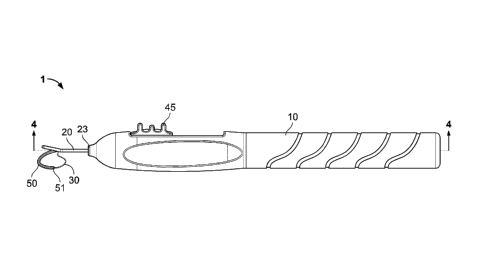
FIG. 1 shows a side view of the ophthalmic surgical instrument according to
the
invention;
FIG. 2 shows the instrument with the housing cover removed;
FIG. 3 shows an exploded view of the instrument;
6
Date Recue/Date Received 2023-01-30
FIG. 4 shows a cross-sectional view of the instrument along lines IV-IV of
FIG. 1;
FIG. 5 shows an alternative embodiment of the snare;
FIG. 6 shows an alternative embodiment of the instrument, with an external
light
source;
FIG. 7 shows another alternative embodiment of the invention;
FIG. 8 shows an enlarged view of circle 8 in FIG. 7;
FIG. 9 shows another alternative embodiment of the invention; and
FIG. 10 shows a further embodiment of the invention.
DETAILED DESCRIPTION OF THE PREFERRED EMBODIMENTS
Turning to the drawings, FIGS. 1-3 show an ophthalmic surgical instrument 1
that
has a housing 10, an elongated shaft in the form of a needle 20 having a
distal end 21, an
opening 22 in a side wall thereof, and a snare 30 formed by a wire, for
severing lenticular
tissue. The elongated shaft 20 is dimensioned for passage through a corneal
incision and
has a proximal end portion 23 that may be integrally formed with or attached
to the housing
or to a slider cartridge 40 shown in FIG. 2.
The snare 30 of the ophthalmic surgical instrument 1 is movable relative to
and
within the elongated shaft 20 via an actuation mechanism formed by slider
cartridge 40 and
slider button 45, which rests in channel 41 of slider cartridge 40. Slider
cartridge 40 is
accessible through an opening 15 in housing 10, A first end of snare 30 is
connected to
7
Date Recue/Date Received 2023-01-30
slider button 45, as shown in FIG. 4, and the second end of snare 30 is fixed
within the
housing, so that moving slider button 45 along channel 41 expands and retracts
looped
segment 33 formed by snare 30. Retracting looped segment 33 by sliding button
45 away
from distal end 22 allows snare 30 to bisect a lens that is disposed within
loop 33 during
surgery.
The snare 30 is fabricated from a pliable, metal material, such as, for
example,
nickel-titanium or any other suitable superelastic material. The snare may be
fabricated
from any suitable ductile material. Surrounding the snare 30 is a light-
conducting tube 50,
which extends at least partially around the looped segment 33. In the
embodiment of
FIGS. 1-4, tube 50 terminates at a distal end 51, which is located at a bottom
of the looped
segment 33. As shown in FIG. 4, tube 50 extends around the top portion of
looped
segment 33, enters the elongated shaft 20 with snare 30, extends through
slider cartridge
40, and connects to a light source 60, which is disposed in housing 10. Light
source 60
can be connected to power source 70, such as a battery, also disposed in
housing 10, so
that the ophthalmic surgical instrument 1 is completely portable and wireless.
The light source 60 may be a light-emitting diode (LED), a compact fluorescent
lamp, an incandescent light bulb, or any other suitable source of light. The
light source 60 is
in communication with the tube 50 so that the light from the light source is
emitted out of
the tube and out of distal end 51. Tube 50 is also preferably made of a
flexible, translucent
material such as polyurethane, so that the light is emitted along the length
of the tube 50
8
Date Recue/Date Received 2023-01-30
and is visible along the entire length. In this embodiment, the light would
appear as a bright
spot at the distal end 51 exit as well. In another embodiment, Tube 50 is made
of an
opaque material, or is covered by an opaque coating or covering, so that only
the light
exiting out of distal end 51 is visible. In one embodiment, tube 50 can be
covered by a
metal covering.
In use, the elongated shaft 20 is inserted through a corneal incision and a
capsulorhexis to position the distal end portion 21 around a surface of the
lens L. The
surgeon is able to use the light emitted from the tube 50 appropriately
position the snare
30 relative to the lens "L." With the looped segment 33 in the selected
position, which is
verified using the light transmitted out of the bottom 51 of tube 50, the
looped segment
33 is transitioned from the dilated configuration to the contracted
configuration, thereby
severing the lens "L."
FIG. 5 shows an alternative embodiment of the invention, where device 100 has
an
elongated shaft 200 with an opening 220 through which a snare 300 formed by
wire
extends in a looped segment 330. Snare 300 is completely encased in a light-
conducting
tube 500, which is connected to a light source 600, in the same manner as
described
above with respect to FIGS. 1-4. Tube 500 is transparent or translucent, so
that the light
from light source 600 is visible along the entire extent of the snare. Tube
500 is thin
enough so that snare 300 surrounded by tube 500 is still able to bisect a lens
when snare
300 is moved to the retracted position in the manner described above with
respect to FIGS.
9
Date Recue/Date Received 2023-01-30
1-4 (using the same slider mechanism as described above).
FIG. 6 shows another alternative embodiment, where light source 660 is located
outside the housing 10 of ophthalmic surgical instrument 1. Snare 350
surrounded by tube
550 extends entirely through the housing and out to remote light source 660,
which can be
located on a remote device or by itself. This embodiment allows for the use of
a larger,
more powerful light source and a larger power supply than may be available to
place inside
housing 10.
An alternative embodiment of the invention is shown in FIGS. 7 and 8. Here, a
light-
conducting element in the form of a solid filament 5500 extends parallel to
snare 3000, and
terminates at a mid-point of looped segment 3300 of snare 3000. A coiled cover
4400
surrounds the snare 3000 and filament 5500 to keep the two components
together. Cover
4400 can be formed of metal wire or any other suitable material, such as a
polymer, or any
other suitable mixture of materials. In this embodiment, the light from
filament 5500 exits
out of end 5510 and forms a bright spot behind the lens during surgery, in the
same
manner as explained above with respect to FIGS 1-4. Filament 5500 is connected
to a light
source that is disposed in the housing 10 or in a location remote from housing
10 in the
same manner as disclosed with the embodiments of FIGS. 1-6.
FIG. 9 shows a further embodiment of the invention, which is identical to the
embodiment of FIGS. 7 and 8, using the instrument of FIGS. 1-6, except that in
this
Date Recue/Date Received 2023-01-30
situation, cover 8000 is in the form of a woven material, typically a metallic
tape or thread,
but any other suitable materials could be used as well. It is also envisioned
that a cover
could be constructed of a solid tube or a molded material that covers both the
snare 3000
and the filament 5500.
A further embodiment is shown in FIG. 10, here the ophthalmic surgical
instrument 1
is identical to the instrument shown in FIGS. 1-4, except that here, snare 30
is bent in two
places in opposite directions at a bottom of looped portion 33, in the form of
a Z- or 5-
shape, so that an intermediate section 340 between bends 341 and 342 extends
upward
toward elongated shaft 20, obliquely to the extent of looped portion 33. Tube
50 terminates
in the intermediate section 340, so that distal end 51 is aimed toward
elongated shaft 20.
Thus, the bright spot formed by the light exiting tube 50 is aimed toward the
surgeon during
surgery (along arrow A), and is thus more visible, even when viewed through a
lens that is
substantially opaque with a cataract. The snare of FIG. 10 could also be used
in an
embodiment where the light-conducting element is in the form of a solid
filament such as
shown by filament 5500 in FIGS. 7-9. In either case, the end of the light-
conducting
element is aimed back toward the elongated shaft 20, so that the brightest
part of the
apparatus is aimed at the surgeon, thus making the snare more visible behind
the lens.
The light-conducting element could be covered or coated so that the light is
only visible at
end 51, such as shown in the embodiment of FIGS. 7-9, or can be uncovered so
that light
is visible along the extent of the light-conducting element, i.e., tube 50.
11
Date Recue/Date Received 2023-01-30
Accordingly, while only a few embodiments of the present invention have been
shown and described, it is obvious that many changes and modifications may be
made
thereunto without departing from the spirit and scope of the invention.
12
Date Recue/Date Received 2023-01-30