Note: Descriptions are shown in the official language in which they were submitted.
WO 2022/031889
PCT/US2021/044608
HANDLING POSITIONING REFERENCE SIGNALS IN WIRELESS SYSTEMS
CROSS-REFERENCE TO RELATED APPLICATIONS
[0001] This application claims the benefit of Provisional U.S.
Patent Application No. 63/061,651, filed
August 5, 2020, Provisional U.S. Patent No. 63/091,600, filed October 14,
2020, Provisional U.S. Patent
Application No. 63/168,018, filed March 30, 2021 and Provisional U.S. Patent
Application No. 63/185,432,
filed May 7, 2021, the disclosure of which is incorporated herein by reference
in its entirety.
BACKGROUND
[0002] Mobile communication technologies continue to evolve. A
fifth generation of mobile
communication radio access technologies (RAT) may be referred to as 5G or new
radio (NR). Previous
(e.g., legacy) generations of mobile communication RAT may include, for
example, fourth generation (4G)
or long term evolution (LTE). A mobile communication system such as a 5G/NR
communication system
may utilize reference signals such as a positioning reference signal (PRS)
and/or a sounding reference
signal (SRS) for positioning to provide positioning related services to a
wireless transmit receive unit
(WTRU). The transmission and/or reception of these reference signals may be
improved to decrease the
latency/overhead and increase the accuracy of the positioning related
services.
SUMMARY
[0003] Systems, methods, and instrumentalities are described herein
regarding positioning reference
siganls. In accordance with one or more embodiments, a wireless
transmit/receive unit (WTRU) may be
configured to receive information regarding a first muting pattern associated
with a set of positioning
reference signal (PRS) time resources and information regarding a second
muting pattern associated with
the set of PRS time resources. The WTRU may determine, while operating in
accordance with the first
muting pattern, that a PRS transmission is to collide with a non-PRS
transmission (e.g., a control channel
transmission or a data channel transmission) in a first time resource of the
set of PRS time resources. The
WTRU may determine that the PRS transmission has a lower priority than the non-
PRS transmission and
may, in response, receive the non-PRS transmission, select, based on the first
muting pattern and the
second muting pattern, a second time resource from the set of PRS time
resources that corresponds to an
1
CA 03188083 2023- 2- 1
WO 2022/031889
PCT/US2021/044608
earliest unmuted PRS transmission after the non-PRS transmission, and receive,
using the second time
resource, the earliest unmuted PRS transmission.
[0004] In embodiments, the WTRU may be configured to receive an
indication of a priority associated
with the first time resource and determine that the PRS transmission has the
lower priority than the non-
PRS transmission based on the indication. The indication may be included in a
radio resource control
(RRC) message, a media access control (MAC) control element (CE), or downlink
control information
(DCI). In embodiments, the earliest unmuted PRS transmission described above
may be received in
accordance with the second muting pattern after the WTRU dertermines that a
first unmuted PRS
transmission to be received after the non-PRS transmission in accordance with
the first muting pattern is
later in time than this earliest unmuted PRS transmission.
[0005] In embodiments, the WTRU may be configured to operate in accordance
with the second PRS
muting pattern after receiving the earliest unmuted PRS transmission using the
second time resource, or
the WTRU may be configured to switch back to operating in according with the
first muting pattern after
receiving the earliest unmuted PRS transmission using the second time
resource. In the latter case, the
WTRU may switch back to operating in according with the first muting pattern
based on an indication
received from a network (e.g., the WTRU may receive information from the
network that the first muting
pattern is the default muting pattern for the WTRU).
[0006] In embodiments, the WTRU may be configured to consider
priorities of positioning reference
signals in various aspects of the WTRU's operation including, for example,
measurement and reporting,
rate matching, puncturing, simultaneous transmission and/or reception of a
positioning reference signal
with other uplink/downlink transmissions and/or receptions, etc.
BRIEF DESCRIPTION OF THE DRAWINGS
[0007] FIG. 1A is a system diagram illustrating an example
communications system in which one or
more disclosed embodiments may be implemented.
[0008] FIG. 1B is a system diagram illustrating an example wireless
transmit/receive unit (WTRU) that
may be used within the communications system illustrated in FIG. 1A according
to an embodiment.
[0009] FIG. 1C is a system diagram illustrating an example radio
access network (RAN) and an example
core network (CN) that may be used within the communications system
illustrated in FIG. 1A according to
an embodiment.
[0010] FIG. 1D is a system diagram illustrating a further example
RAN and a further example CN that
may be used within the communications system illustrated in FIG. 1A according
to an embodiment.
2
CA 03188083 2023- 2- 1
WO 2022/031889
PCT/US2021/044608
[0011] FIG. 2 illustrates a first example configuration structure
associated with a positioning reference
signal.
[0012] FIG. 3 illustrates a second example configuration structure
associating a positioning reference
signal.
[0013] FIG. 4 illustrates an example of a WTRU changing a muting
pattern based on PRS reception
activities in a reference signal resource.
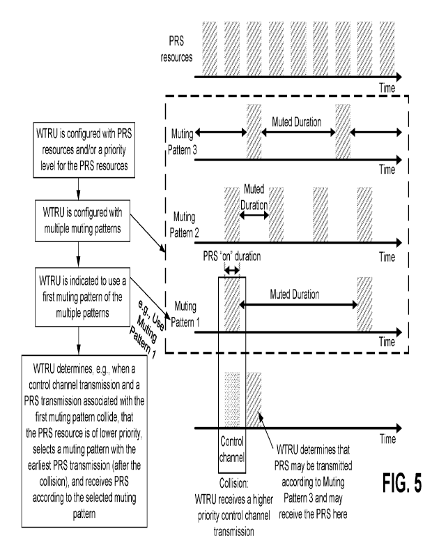
[0014] FIG. 5 illustrates an example of a WTRU changing a muting
pattern based on the deprioritization
of a positioning reference signal resource.
[0015] FIG. 6 illustrates a first example of determining and
reporting a transmission time difference
between a sounding reference signal for positioning (SRSp) transmission and a
positioning reference
signal (PRS) transmission.
[0016] FIG. 7 illustrates a second example of determining and
reporting a transmission time difference
between an SRSp transmission and a PRS transmission.
DETAILED DESCRIPTION
[0017] FIG. 1A is a diagram illustrating an example communications
system 100 in which one or more
disclosed embodiments may be implemented. The communications system 100 may be
a multiple access
system that provides content, such as voice, data, video, messaging,
broadcast, etc., to multiple wireless
users. The communications system 100 may enable multiple wireless users to
access such content
through the sharing of system resources, including wireless bandwidth. For
example, the communications
systems 100 may employ one or more channel access methods, such as code
division multiple access
(CDMA), time division multiple access (TDMA), frequency division multiple
access (FDMA), orthogonal
FDMA (OFDMA), single-carrier FDMA (SC-FDMA), zero-tail unique-word DFT-Spread
OFDM (ZT UW
DTS-s OFDM), unique word OFDM (UW-OFDM), resource block-filtered OFDM, filter
bank multicarrier
(FBMC), and the like.
[0018] As shown in FIG. 1A, the communications system 100 may
include wireless transmit/receive
units (WTRUs) 102a, 102b, 102c, 102d, a RAN 104/113, a CN 106/115, a public
switched telephone
network (PSTN) 108, the Internet 110, and other networks 112, though it will
be appreciated that the
disclosed embodiments contemplate any number of WTRUs, base stations,
networks, and/or network
elements. Each of the WTRUs 102a, 102b, 102c, 102d may be any type of device
configured to operate
and/or communicate in a wireless environment. By way of example, the WTRUs
102a, 102b, 102c, 102d,
any of which may be referred to as a "station" and/or a "STA", may be
configured to transmit and/or receive
wireless signals and may include a user equipment (UE), a mobile station, a
fixed or mobile subscriber unit,
3
CA 03188083 2023- 2- 1
WO 2022/031889
PCT/US2021/044608
a subscription-based unit, a pager, a cellular telephone, a personal digital
assistant (FDA), a smartphone, a
laptop, a netbook, a personal computer, a wireless sensor, a hotspot or Mi-Fi
device, an Internet of Things
(loT) device, a watch or other wearable, a head-mounted display (HMD), a
vehicle, a drone, a medical
device and applications (e.g., remote surgery), an industrial device and
applications (e.g., a robot and/or
other wireless devices operating in an industrial and/or an automated
processing chain contexts), a
consumer electronics device, a device operating on commercial and/or
industrial wireless networks, and
the like. Any of the WTRUs 102a, 102b, 102c and 102d may be interchangeably
referred to as a UE.
[0019] The communications systems 100 may also include a base
station 114a and/or a base station
114b. Each of the base stations 114a, 114b may be any type of device
configured to wirelessly interface
with at least one of the WTRUs 102a, 102b, 102c, 102d to facilitate access to
one or more communication
networks, such as the CN 106/115, the Internet 110, and/or the other networks
112. By way of example,
the base stations 114a, 114b may be a base transceiver station (BTS), a Node-
B, an eNode B, a Home
Node B, a Home eNode B, a gNB, a NR NodeB, a site controller, an access point
(AP), a wireless router,
and the like. While the base stations 114a, 114b are each depicted as a single
element, it will be
appreciated that the base stations 114a, 114b may include any number of
interconnected base stations
and/or network elements.
[0020] The base station 114a may be part of the RAN 104/113, which
may also include other base
stations and/or network elements (not shown), such as a base station
controller (BSC), a radio network
controller (RNC), relay nodes, etc. The base station 114a and/or the base
station 114b may be configured
to transmit and/or receive wireless signals on one or more carrier
frequencies, which may be referred to as
a cell (not shown). These frequencies may be in licensed spectrum, unlicensed
spectrum, or a
combination of licensed and unlicensed spectrum. A cell may provide coverage
for a wireless service to a
specific geographical area that may be relatively fixed or that may change
over time. The cell may further
be divided into cell sectors. For example, the cell associated with the base
station 114a may be divided
into three sectors. Thus, in one embodiment, the base station 114a may include
three transceivers, i.e.,
one for each sector of the cell. In an embodiment, the base station 114a may
employ multiple-input
multiple output (M IMO) technology and may utilize multiple transceivers for
each sector of the cell. For
example, beamforming may be used to transmit and/or receive signals in desired
spatial directions.
[0021] The base stations 114a, 114b may communicate with one or
more of the WTRUs 102a, 102b,
102c, 102d over an air interface 116, which may be any suitable wireless
communication link (e.g., radio
frequency (RF), microwave, centimeter wave, micrometer wave, infrared (IR),
ultraviolet (UV), visible light,
etc.). The air interface 116 may be established using any suitable radio
access technology (RAT).
4
CA 03188083 2023- 2- 1
WO 2022/031889
PCT/US2021/044608
[0022] More specifically, as noted above, the communications
system 100 may be a multiple access
system and may employ one or more channel access schemes, such as CD MA, TDMA,
FDMA, OFDMA,
SC-FDMA, and the like. For example, the base station 114a in the RAN 104/113
and the WTRUs 102a,
102b, 102c may implement a radio technology such as Universal Mobile
Telecommunications System
(UMTS) Terrestrial Radio Access (UTRA), which may establish the air interface
115/116/117 using
wideband CDMA (WCDMA). WCDMA may include communication protocols such as High-
Speed Packet
Access (HSPA) and/or Evolved HSPA (HSPA-F). HSPA may include High-Speed
Downlink (DL) Packet
Access (HSDPA) and/or High-Speed UL Packet Access (HSUPA).
[0023] In an embodiment, the base station 114a and the WTRUs 102a,
102b, 102c may implement a
radio technology such as Evolved UMTS Terrestrial Radio Access (E-UTRA), which
may establish the air
interface 116 using Long Term Evolution (LTE) and/or LTE-Advanced (LTE-A)
and/or LTE-Advanced Pro
(LTE-A Pro).
[0024] In an embodiment, the base station 114a and the WTRUs 102a,
102b, 102c may implement a
radio technology such as NR Radio Access , which may establish the air
interface 116 using New Radio
(NR).
[0025] In an embodiment, the base station 114a and the WTRUs 102a,
102b, 102c may implement
multiple radio access technologies. For example, the base station 114a and the
WTRUs 102a, 102b, 102c
may implement LTE radio access and NR radio access together, for instance
using dual connectivity (DC)
principles. Thus, the air interface utilized by WTRUs 102a, 102b, 102c may be
characterized by multiple
types of radio access technologies and/or transmissions sent to/from multiple
types of base stations (e.g., a
eNB and a gNB).
[0026] In other embodiments, the base station 114a and the WTRUs
102a, 102b, 102c may implement
radio technologies such as IEEE 802.11 (i.e., Wireless Fidelity (WiFi), IEEE
802.16 (i.e., Worldwide
lnteroperability for Microwave Access (WiMAX)), CDMA2000, CDMA2000 1X,
CDMA2000 EV-DO, Interim
Standard 2000 (IS-2000), Interim Standard 95 (IS-95), Interim Standard 856 (IS-
856), Global System for
Mobile communications (GSM), Enhanced Data rates for GSM Evolution (EDGE), GSM
EDGE (GERAN),
and the like.
[0027] The base station 114b in FIG. 1A may be a wireless router,
Home Node B, Home eNode B, or
access point, for example, and may utilize any suitable RAT for facilitating
wireless connectivity in a
localized area, such as a place of business, a home, a vehicle, a campus, an
industrial facility, an air
corridor (e.g., for use by drones), a roadway, and the like. In one
embodiment, the base station 114b and
the WTRUs 102c, 102d may implement a radio technology such as IEEE 802.11 to
establish a wireless
local area network (WLAN). In an embodiment, the base station 114b and the
WTRUs 102c, 102d may
CA 03188083 2023- 2- 1
WO 2022/031889
PCT/US2021/044608
implement a radio technology such as IEEE 802.15 to establish a wireless
personal area network (WPAN).
In yet another embodiment, the base station 114b and the WTRUs 102c, 102d may
utilize a cellular-based
RAT (e.g., WCDMA, CDMA2000, GSM, LTE, LTE-A, LTE-A Pro, NR etc.) to establish
a picocell or
femtocell. As shown in FIG. 1A, the base station 114b may have a direct
connection to the Internet 110.
Thus, the base station 114b may not be required to access the Internet 110 via
the CN 106/115.
[0028] The RAN 104/113 may be in communication with the ON
106/115, which may be any type of
network configured to provide voice, data, applications, and/or voice over
internet protocol (VolP) services
to one or more of the WTRUs 102a, 102b, 102c, 102d. The data may have varying
quality of service (QoS)
requirements, such as differing throughput requirements, latency requirements,
error tolerance
requirements, reliability requirements, data throughput requirements, mobility
requirements, and the like.
The CN 106/115 may provide call control, billing services, mobile location-
based services, pre-paid calling,
Internet connectivity, video distribution, etc., and/or perform high-level
security functions, such as user
authentication. Although not shown in FIG. 1A, it will be appreciated that the
RAN 104/113 and/or the ON
106/115 may be in direct or indirect communication with other RANs that employ
the same RAT as the
RAN 104/113 or a different RAT. For example, in addition to being connected to
the RAN 104/113, which
may be utilizing a NR radio technology, the CN 106/115 may also be in
communication with another RAN
(not shown) employing a GSM, UMTS, CDMA 2000, WiMAX, E-UTRA, or WiFi radio
technology.
[0029] The CN 106/115 may also serve as a gateway for the WTRUs
102a, 102b, 102c, 102d to access
the PSTN 108, the Internet 110, and/or the other networks 112. The PSTN 108
may include circuit-
switched telephone networks that provide plain old telephone service (POTS).
The Internet 110 may
include a global system of interconnected computer networks and devices that
use common
communication protocols, such as the transmission control protocol (TOP), user
datagram protocol (UDP)
and/or the internet protocol (IP) in the TCP/IP internet protocol suite. The
networks 112 may include wired
and/or wireless communications networks owned and/or operated by other service
providers. For example,
the networks 112 may include another ON connected to one or more RANs, which
may employ the same
RAT as the RAN 104/113 or a different RAT.
[0030] Some or all of the WTRUs 102a, 102b, 102c, 102d in the
communications system 100 may
include multi-mode capabilities (e.g., the WTRUs 102a, 102b, 102c, 102d may
include multiple transceivers
for communicating with different wireless networks over different wireless
links). For example, the VVTRU
102c shown in FIG. 1A may be configured to communicate with the base station
114a, which may employ a
cellular-based radio technology, and with the base station 114b, which may
employ an IEEE 802 radio
technology.
6
CA 03188083 2023- 2- 1
WO 2022/031889
PCT/US2021/044608
[0031] FIG. 1B is a system diagram illustrating an example WTRU
102. As shown in FIG. 1B, the
WTRU 102 may include a processor 118, a transceiver 120, a transmit/receive
element 122, a
speaker/microphone 124, a keypad 126, a display/touchpad 128, non-removable
memory 130, removable
memory 132, a power source 134, a global positioning system (GPS) chipset 136,
and/or other peripherals
138, among others. It will be appreciated that the WTRU 102 may include any
sub-combination of the
foregoing elements while remaining consistent with an embodiment.
[0032] The processor 118 may be a general purpose processor, a
special purpose processor, a
conventional processor, a digital signal processor (DSP), a plurality of
microprocessors, one or more
microprocessors in association with a DSP core, a controller, a
microcontroller, Application Specific
Integrated Circuits (ASICs), Field Programmable Gate Arrays (FPGAs) circuits,
any other type of integrated
circuit (IC), a state machine, and the like. The processor 118 may perform
signal coding, data processing,
power control, input/output processing, and/or any other functionality that
enables the WTRU 102 to
operate in a wireless environment. The processor 118 may be coupled to the
transceiver 120, which may
be coupled to the transmit/receive element 122. While FIG. 1B depicts the
processor 118 and the
transceiver 120 as separate components, it will be appreciated that the
processor 118 and the transceiver
120 may be integrated together in an electronic package or chip.
[0033] The transmit/receive element 122 may be configured to
transmit signals to, or receive signals
from, a base station (e.g., the base station 114a) over the air interface 116.
For example, in one
embodiment, the transmit/receive element 122 may be an antenna configured to
transmit and/or receive
RF signals. In an embodiment, the transmit/receive element 122 may be an
emitter/detector configured to
transmit and/or receive IR, UV, or visible light signals, for example. In yet
another embodiment, the
transmit/receive element 122 may be configured to transmit and/or receive both
RF and light signals. It will
be appreciated that the transmit/receive element 122 may be configured to
transmit and/or receive any
combination of wireless signals.
[0034] Although the transmit/receive element 122 is depicted in
FIG. 1B as a single element, the WTRU
102 may include any number of transmit/receive elements 122. More
specifically, the WTRU 102 may
employ MIMO technology. Thus, in one embodiment, the WTRU 102 may include two
or more
transmit/receive elements 122 (e.g., multiple antennas) for transmitting and
receiving wireless signals over
the air interface 116.
[0035] The transceiver 120 may be configured to modulate the
signals that are to be transmitted by the
transmit/receive element 122 and to demodulate the signals that are received
by the transmit/receive
element 122. As noted above, the WTRU 102 may have multi-mode capabilities.
Thus, the transceiver
7
CA 03188083 2023- 2- 1
WO 2022/031889
PCT/US2021/044608
120 may include multiple transceivers for enabling the WTRU 102 to communicate
via multiple RATs, such
as NR and IEEE 802.11, for example.
[0036] The processor 118 of the WTRU 102 may be coupled to, and
may receive user input data from,
the speaker/microphone 124, the keypad 126, and/or the display/touchpad 128
(e.g., a liquid crystal display
(LCD) display unit or organic light-emitting diode (OLED) display unit). The
processor 118 may also output
user data to the speaker/microphone 124, the keypad 126, and/or the
display/touchpad 128. In addition,
the processor 118 may access information from, and store data in, any type of
suitable memory, such as
the non-removable memory 130 and/or the removable memory 132. The non-
removable memory 130 may
include random-access memory (RAM), read-only memory (ROM), a hard disk, or
any other type of
memory storage device. The removable memory 132 may include a subscriber
identity module (SIM) card,
a memory stick, a secure digital (SD) memory card, and the like. In other
embodiments, the processor 118
may access information from, and store data in, memory that is not physically
located on the WTRU 102,
such as on a server or a home computer (not shown).
[0037] The processor 118 may receive power from the power source
134, and may be configured to
distribute and/or control the power to the other components in the WTRU 102.
The power source 134 may
be any suitable device for powering the WTRU 102. For example, the power
source 134 may include one
or more dry cell batteries (e.g., nickel-cadmium (NiCd), nickel-zinc (NiZn),
nickel metal hydride (NiMH),
lithium-ion (Li-ion), etc.), solar cells, fuel cells, and the like.
[0038] The processor 118 may also be coupled to the GPS chipset
136, which may be configured to
provide location information (e.g., longitude and latitude) regarding the
current location of the WTRU 102.
In addition to, or in lieu of, the information from the GPS chipset 136, the
WTRU 102 may receive location
information over the air interface 116 from a base station (e.g., base
stations 114a, 114b) and/or determine
its location based on the timing of the signals being received from two or
more nearby base stations. It will
be appreciated that the WTRU 102 may acquire location information by way of
any suitable location-
determination method while remaining consistent with an embodiment.
[0039] The processor 118 may further be coupled to other
peripherals 138, which may include one or
more software and/or hardware modules that provide additional features,
functionality and/or wired or
wireless connectivity. For example, the peripherals 138 may include an
accelerometer, an e-compass, a
satellite transceiver, a digital camera (for photographs and/or video), a
universal serial bus (USB) port, a
vibration device, a television transceiver, a hands free headset, a BluetoothO
module, a frequency
modulated (FM) radio unit, a digital music player, a media player, a video
game player module, an Internet
browser, a Virtual Reality and/or Augmented Reality (VR/AR) device, an
activity tracker, and the like. The
peripherals 138 may include one or more sensors, the sensors may be one or
more of a gyroscope, an
8
CA 03188083 2023- 2- 1
WO 2022/031889
PCT/US2021/044608
accelerometer, a hall effect sensor, a magnetometer, an orientation sensor, a
proximity sensor, a
temperature sensor, a time sensor; a geolocation sensor; an altimeter, a light
sensor, a touch sensor, a
magnetometer, a barometer, a gesture sensor, a biometric sensor, and/or a
humidity sensor.
[0040] The WTRU 102 may include a full duplex radio for which
transmission and reception of some or
all of the signals (e.g., associated with particular subframes for both the UL
(e.g., for transmission) and
downlink (e.g., for reception) may be concurrent and/or simultaneous. The full
duplex radio may include an
interference management unit to reduce and or substantially eliminate self-
interference via either hardware
(e.g., a choke) or signal processing via a processor (e.g., a separate
processor (not shown) or via
processor 118). In an embodiment, the WRTU 102 may include a half-duplex radio
for which transmission
and reception of some or all of the signals (e.g., associated with particular
subframes for either the UL
(e.g., for transmission) or the downlink (e.g., for reception)).
[0041] FIG. 10 is a system diagram illustrating the RAN 104 and the
ON 106 according to an
embodiment. As noted above, the RAN 104 may employ an E-UTRA radio technology
to communicate
with the WTRUs 102a, 102b, 102c over the air interface 116. The RAN 104 may
also be in communication
with the CN 106.
[0042] The RAN 104 may include eNode-Bs 160a, 160b, 160c, though it
will be appreciated that the
RAN 104 may include any number of eNode-Bs while remaining consistent with an
embodiment. The
eNode-Bs 160a, 160b, 160c may each include one or more transceivers for
communicating with the
WTRUs 102a, 102b, 102c over the air interface 116. In one embodiment, the
eNode-Bs 160a, 160b, 160c
may implement MIMO technology. Thus, the eNode-B 160a, for example, may use
multiple antennas to
transmit wireless signals to, and/or receive wireless signals from, the WTRU
102a.
[0043] Each of the eNode-Bs 160a, 160b, 160c may be associated with
a particular cell (not shown)
and may be configured to handle radio resource management decisions, handover
decisions, scheduling of
users in the UL and/or DL, and the like. As shown in FIG. 1C, the eNode-Bs
160a, 160b, 160c may
communicate with one another over an X2 interface.
[0044] The ON 106 shown in FIG. 10 may include a mobility
management entity (MME) 162, a serving
gateway (SGW) 164, and a packet data network (PDN) gateway (or PGW) 166. While
each of the
foregoing elements are depicted as part of the ON 106, it will be appreciated
that any of these elements
may be owned and/or operated by an entity other than the ON operator.
[0045] The MME 162 may be connected to each of the eNode-Bs 162a,
162b, 162c in the RAN 104 via
an Si interface and may serve as a control node. For example, the MME 162 may
be responsible for
authenticating users of the WTRUs 102a, 102b, 102c, bearer
activation/deactivation, selecting a particular
serving gateway during an initial attach of the WTRUs 102a, 102b, 102c, and
the like. The MME 162 may
9
CA 03188083 2023- 2- 1
WO 2022/031889
PCT/US2021/044608
provide a control plane function for switching between the RAN 104 and other
RANs (not shown) that
employ other radio technologies, such as GSM and/or WCDMA.
[0046] The SGW 164 may be connected to each of the eNode Bs 160a,
160b, 160c in the RAN 104 via
the Si interface. The SGW 164 may generally route and forward user data
packets to/from the WTRUs
102a, 102b, 102c, The SGW 164 may perform other functions, such as anchoring
user planes during inter-
eNode B handovers, triggering paging when DL data is available for the WTRUs
102a, 102b, 102c,
managing and storing contexts of the WTRUs 102a, 102b, 102c, and the like.
[0047] The SGW 164 may be connected to the PGW 166, which may
provide the WTRUs 102a, 102b,
102c with access to packet-switched networks, such as the Internet 110, to
facilitate communications
between the WTRUs 102a, 102b, 102c and IP-enabled devices.
[0048] The ON 106 may facilitate communications with other
networks. For example, the ON 106 may
provide the WTRUs 102a, 102b, 102c with access to circuit-switched networks,
such as the PSTN 108, to
facilitate communications between the WTRUs 102a, 102b, 102c and traditional
land-line communications
devices. For example, the ON 106 may include, or may communicate with, an IP
gateway (e.g., an IP
multimedia subsystem (IMS) server) that serves as an interface between the ON
106 and the PSTN 108.
In addition, the ON 106 may provide the WTRUs 102a, 102b, 102c with access to
the other networks 112,
which may include other wired and/or wireless networks that are owned and/or
operated by other service
providers.
[0049] Although the WTRU is described in FIGS. 1A-1D as a wireless
terminal, it is contemplated that in
certain representative embodiments that such a terminal may use (e.g.,
temporarily or permanently) wired
communication interfaces with the communication network.
[0050] In representative embodiments, the other network 112 may be
a WLAN.
[0051] A WLAN in Infrastructure Basic Service Set (BSS) mode may have an
Access Point (AP) for the
BSS and one or more stations (STAs) associated with the AP. The AP may have an
access or an interface
to a Distribution System (DS) or another type of wired/wireless network that
carries traffic in to and/or out of
the BSS. Traffic to STAs that originates from outside the BSS may arrive
through the AP and may be
delivered to the STAs. Traffic originating from STAs to destinations outside
the BSS may be sent to the AP
to be delivered to respective destinations. Traffic between STAs within the
BSS may be sent through the
AP, for example, where the source STA may send traffic to the AP and the AP
may deliver the traffic to the
destination STA. The traffic between STAs within a BSS may be considered
and/or referred to as peer-to-
peer traffic. The peer-to-peer traffic may be sent between (e.g., directly
between) the source and
destination STAs with a direct link setup (DLS). In certain representative
embodiments, the DLS may use
an 802.11e DLS or an 802.11z tunneled DLS (TDLS). A WLAN using an Independent
BSS (IBSS) mode
CA 03188083 2023- 2- 1
WO 2022/031889
PCT/US2021/044608
may not have an AP, and the STAs (e.g., all of the STAs) within or using the
IBSS may communicate
directly with each other. The IBSS mode of communication may sometimes be
referred to herein as an
"ad-hoc" mode of communication.
[0052] When using the 802.11ac infrastructure mode of operation or
a similar mode of operations, the
AP may transmit a beacon on a fixed channel, such as a primary channel. The
primary channel may be a
fixed width (e.g., 20 MHz wide bandwidth) or a dynamically set width via
signaling. The primary channel
may be the operating channel of the BSS and may be used by the STAs to
establish a connection with the
AP. In certain representative embodiments, Carrier Sense Multiple Access with
Collision Avoidance
(CSMA/CA) may be implemented, for example in in 802.11 systems. For CSMA/CA,
the STAs (e.g., every
STA), including the AP, may sense the primary channel. If the primary channel
is sensed/detected and/or
determined to be busy by a particular STA, the particular STA may back off.
One STA (e.g., only one
station) may transmit at any given time in a given BSS.
[0053] High Throughput (HT) STAs may use a 40 MHz wide channel for
communication, for example,
via a combination of the primary 20 MHz channel with an adjacent or
nonadjacent 20 MHz channel to form
a 40 MHz wide channel.
[0054] Very High Throughput (VHT) STAs may support 20MHz, 40 MHz, 80 MHz,
and/or 160 MHz wide
channels. The 40 MHz, and/or 80 MHz, channels may be formed by combining
contiguous 20 MHz
channels. A 160 MHz channel may be formed by combining 8 contiguous 20 MHz
channels, or by
combining two non-contiguous 80 MHz channels, which may be referred to as an
80+80 configuration. For
the 80+80 configuration, the data, after channel encoding, may be passed
through a segment parser that
may divide the data into two streams. Inverse Fast Fourier Transform (IFFT)
processing, and time domain
processing, may be done on each stream separately. The streams may be mapped
on to the two 80 MHz
channels, and the data may be transmitted by a transmitting STA. At the
receiver of the receiving STA, the
above described operation for the 80+80 configuration may be reversed, and the
combined data may be
sent to the Medium Access Control (MAC).
[0055] Sub 1 GHz modes of operation are supported by 802.11af and
802.11ah. The channel operating
bandwidths, and carriers, are reduced in 802.11af and 802.11ah relative to
those used in 802.11n, and
802.11ac. 802.11af supports 5 MHz, 10 MHz and 20 MHz bandwidths in the TV
White Space (TVWS)
spectrum, and 802.11ah supports 1 MHz, 2 MHz, 4 MHz, 8 MHz, and 16 MHz
bandwidths using non-
TVWS spectrum. According to a representative embodiment, 802.11ah may support
Meter Type
Control/Machine-Type Communications, such as MTC devices in a macro coverage
area. MTC devices
may have certain capabilities, for example, limited capabilities including
support for (e.g., only support for)
11
CA 03188083 2023- 2- 1
WO 2022/031889
PCT/US2021/044608
certain and/or limited bandwidths. The MTC devices may include a battery with
a battery life above a
threshold (e.g., to maintain a very long battery life).
[0056] WLAN systems, which may support multiple channels, and
channel bandwidths, such as
802.11n, 802.11ac, 802.11af, and 802.11ah, include a channel which may be
designated as the primary
channel. The primary channel may have a bandwidth equal to the largest common
operating bandwidth
supported by all STAs in the BSS. The bandwidth of the primary channel may be
set and/or limited by a
STA, from among all STAs in operating in a BSS, which supports the smallest
bandwidth operating mode.
In the example of 802.11ah, the primary channel may be 1 MHz wide for STAs
(e.g., MTC type devices)
that support (e.g., only support) a 1 MHz mode, even if the AP, and other STAs
in the BSS support 2 MHz,
4 MHz, 8 MHz, 16 MHz, and/or other channel bandwidth operating modes. Carrier
sensing and/or Network
Allocation Vector (NAV) settings may depend on the status of the primary
channel. If the primary channel
is busy, for example, due to a STA (which supports only a 1 MHz operating
mode), transmitting to the AP,
the entire available frequency bands may be considered busy even though a
majority of the frequency
bands remains idle and may be available.
[0057] In the United States, the available frequency bands, which
may be used by 802.11ah, are from
902 MHz to 928 MHz. In Korea, the available frequency bands are from 917.5 MHz
to 923.5 MHz. In
Japan, the available frequency bands are from 916.5 MHz to 927.5 MHz. The
total bandwidth available for
802.11ah is 6 MHz to 26 MHz depending on the country code.
[0058] FIG. 1D is a system diagram illustrating the RAN 113 and the
CN 115 according to an
embodiment. As noted above, the RAN 113 may employ an NR radio technology to
communicate with the
WTRUs 102a, 102b, 102c over the air interface 116. The RAN 113 may also be in
communication with the
ON 115.
[0059] The RAN 113 may include gNBs 180a, 180b, 180c, though it
will be appreciated that the RAN
113 may include any number of gNBs while remaining consistent with an
embodiment. The gNBs 180a,
180b, 180c may each include one or more transceivers for communicating with
the WTRUs 102a, 102b,
102c over the air interface 116. In one embodiment, the gNBs 180a, 180b, 180c
may implement MIMO
technology. For example, gNBs 180a, 108b may utilize beamforming to transmit
signals to and/or receive
signals from the gNBs 180a, 180b, 180c. Thus, the gNB 180a, for example, may
use multiple antennas to
transmit wireless signals to, and/or receive wireless signals from, the WTRU
102a. In an embodiment, the
gNBs 180a, 180b, 180c may implement carrier aggregation technology. For
example, the gNB 180a may
transmit multiple component carriers to the WTRU 102a (not shown). A subset of
these component
carriers may be on unlicensed spectrum while the remaining component carriers
may be on licensed
spectrum. In an embodiment, the gNBs 180a, 180b, 180c may implement
Coordinated Multi-Point (CoMP)
12
CA 03188083 2023- 2- 1
WO 2022/031889
PCT/US2021/044608
technology. For example, WTRU 102a may receive coordinated transmissions from
gNB 180a and gNB
180b (and/or gNB 180c).
[0060] The WTRUs 102a, 102b, 102c may communicate with gNBs 180a, 180b, 180c
using
transmissions associated with a scalable numerology. For example, the OFDM
symbol spacing and/or
OFDM subcarrier spacing may vary for different transmissions, different cells,
and/or different portions of
the wireless transmission spectrum. The WTRUs 102a, 102b, 102c may communicate
with gNBs 180a,
180b, 180c using subframe or transmission time intervals (TTIs) of various or
scalable lengths (e.g.,
containing varying number of OFDM symbols and/or lasting varying lengths of
absolute time).
[0061] The gNBs 180a, 180b, 180c may be configured to communicate with the
WTRUs 102a, 102b,
102c in a standalone configuration and/or a non-standalone configuration. In
the standalone configuration,
WTRUs 102a, 102b, 102c may communicate with gNBs 180a, 180b, 180c without also
accessing other
RANs (e.g., such as eNode-Bs 160a, 160b, 160c). In the standalone
configuration, WTRUs 102a, 102b,
102c may utilize one or more of gNBs 180a, 180b, 180c as a mobility anchor
point. In the standalone
configuration, WTRUs 102a, 102b, 102c may communicate with gNBs 180a, 180b,
180c using signals in an
unlicensed band. In a non-standalone configuration WTRUs 102a, 102b, 102c may
communicate
with/connect to gNBs 1802, 180b, 180c while also communicating with/connecting
to another RAN such as
eNode-Bs 160a, 160b, 160c. For example, WTRUs 102a, 102b, 102c may implement
DC principles to
communicate with one or more gNBs 180a, 180b, 180c and one or more eNode-Bs
160a, 160b, 160c
substantially simultaneously. In the non-standalone configuration, eNode-Bs
160a, 160b, 160c may serve
as a mobility anchor for WTRUs 102a, 102b, 102c and gNBs 180a, 180b, 180c may
provide additional
coverage and/or throughput for servicing WTRUs 102a, 102b, 102c.
[0062] Each of the gNBs 180a, 180b, 180c may be associated with a
particular cell (not shown) and
may be configured to handle radio resource management decisions, handover
decisions, scheduling of
users in the UL and/or DL, support of network slicing, dual connectivity,
interworking between NR and E-
UTRA, routing of user plane data towards User Plane Function (UPF) 184a, 184b,
routing of control plane
information towards Access and Mobility Management Function (AM F) 182a, 182b
and the like. As shown
in FIG. 1D, the gNBs 180a, 180b, 180c may communicate with one another over an
Xn interface.
[0063] The CN 115 shown in FIG. 1D may include at least one AMF
182a, 182b, at least one UPF
184a,184b, at least one Session Management Function (SMF) 183a, 183b, and
possibly a Data Network
(DN) 185a, 185b. While each of the foregoing elements are depicted as part of
the ON 115, it will be
appreciated that any of these elements may be owned and/or operated by an
entity other than the ON
operator.
13
CA 03188083 2023- 2- 1
WO 2022/031889
PCT/US2021/044608
[0064] The AMF 182a, 182b may be connected to one or more of the
gNBs 180a, 180b, 180c in the
RAN 113 via an N2 interface and may serve as a control node. For example, the
AMF 182a, 182b may be
responsible for authenticating users of the WTRUs 102a, 102b, 102c, support
for network slicing (e.g.,
handling of different PDU sessions with different requirements), selecting a
particular SMF 183a, 183b,
management of the registration area, termination of NAS signaling, mobility
management, and the like.
Network slicing may be used by the AMF 182a, 182b in order to customize ON
support for WTRUs 102a,
102b, 102c based on the types of services being utilized WTRUs 102a, 102b,
102c. For example, different
network slices may be established for different use cases such as services
relying on ultra-reliable low
latency (URLLC) access, services relying on enhanced massive mobile broadband
(eMBB) access,
services for machine type communication (MTC) access, and/or the like. The AMF
162 may provide a
control plane function for switching between the RAN 113 and other RANs (not
shown) that employ other
radio technologies, such as LTE, LTE-A, LTE-A Pro, and/or non-3GPP access
technologies such as VViFi.
[0065] The SMF 183a, 183b may be connected to an AMF 182a, 182b in
the ON 115 via an N11
interface. The SMF 183a, 183b may also be connected to a UPF 184a, 184b in the
ON 115 via an N4
interface. The SMF 183a, 183b may select and control the UPF 184a, 184b and
configure the routing of
traffic through the UPF 184a, 184b. The SMF 183a, 183b may perform other
functions, such as managing
and allocating UE IP address, managing PDU sessions, controlling policy
enforcement and QoS, providing
downlink data notifications, and the like. A PDU session type may be IP-based,
non-IP based, Ethernet-
based, and the like.
[0066] The UPF 184a, 184b may be connected to one or more of the
gNBs 180a, 180b, 180c in the
RAN 113 via an N3 interface, which may provide the WTRUs 102a, 102b, 102c with
access to packet-
switched networks, such as the Internet 110, to facilitate communications
between the WTRUs 102a, 102b,
102c and IP-enabled devices. The UPF 184, 184b may perform other functions,
such as routing and
forwarding packets, enforcing user plane policies, supporting multi-homed PDU
sessions, handling user
plane QoS, buffering downlink packets, providing mobility anchoring, and the
like.
[0067] The ON 115 may facilitate communications with other
networks. For example, the ON 115 may
include, or may communicate with, an IP gateway (e.g., an IP multimedia
subsystem (IMS) server) that
serves as an interface between the ON 115 and the PSTN 108. In addition, the
ON 115 may provide the
WTRUs 102a, 102b, 102c with access to the other networks 112, which may
include other wired and/or
wireless networks that are owned and/or operated by other service providers.
In one embodiment, the
WTRUs 102a, 102b, 102c may be connected to a local Data Network (DN) 185a,
185b through the UPF
184a, 184b via the N3 interface to the UPF 184a, 184b and an N6 interface
between the UPF 184a, 184b
and the DN 185a, 185b.
14
CA 03188083 2023- 2- 1
WO 2022/031889
PCT/US2021/044608
[0068] In view of Figures 1A-1D, and the corresponding description
of Figures 1A-1D, one or more, or
all, of the functions described herein with regard to one or more of: WTRU
102a-d, Base Station 114a-b,
eNode-B 160a-c, MME 162, SGW 164, PGW 166, gNB 180a-c, AMF 182a-b, UPF 184a-b,
SMF 183a-b,
DN 185a-b, and/or any other device(s) described herein, may be performed by
one or more emulation
devices (not shown). The emulation devices may be one or more devices
configured to emulate one or
more, or all, of the functions described herein. For example, the emulation
devices may be used to test
other devices and/or to simulate network and/or WTRU functions.
[0069] The emulation devices may be designed to implement one or
more tests of other devices in a lab
environment and/or in an operator network environment. For example, the one or
more emulation devices
may perform the one or more, or all, functions while being fully or partially
implemented and/or deployed as
part of a wired and/or wireless communication network in order to test other
devices within the
communication network. The one or more emulation devices may perform the one
or more, or all,
functions while being temporarily implemented/deployed as part of a wired
and/or wireless communication
network. The emulation device may be directly coupled to another device for
purposes of testing and/or
may performing testing using over-the-air wireless communications.
[0070] The one or more emulation devices may perform the one or
more, including all, functions while
not being implemented/deployed as part of a wired and/or wireless
communication network. For example,
the emulation devices may be utilized in a testing scenario in a testing
laboratory and/or a non-deployed
(e.g., testing) wired and/or wireless communication network in order to
implement testing of one or more
components. The one or more emulation devices may be test equipment. Direct RF
coupling and/or
wireless communications via RF circuitry (e.g., which may include one or more
antennas) may be used by
the emulation devices to transmit and/or receive data.
[0071] Reference signals such as a positioning reference signal
(PRS), a sounding reference signal
(SRS) for positioning (SRSp), etc., may be transmitted/received in a mobile
communication system (e.g.,
PRS for a downlink (DL) and SRSp for an uplink (UL)). In some example systems,
a PRS and/or an SRSp
may be given (e.g., by default) lower priorities compared to other types of
signals such as control signals.
This may lead to a PRS and/or SRSp being dropped from transmission and/or
reception if they overlap with
other (e.g., higher priority) signals (e.g., data and/or control channel
transmissions) in time and/or
frequency resources. In at least some situations (e.g., when a low or short
latency for positioning is
desired), giving low priority (e.g., by default) to PRS's and/or SRSp's may
prevent a communication system
from achieving low latency, for example, with respect to positioning related
services.
[0072] Priorities may be provided for (e.g., assigned to) reference
signals such as those used for
positioning, for example, to achieve low latency performance. A PRS may be
configured based on a
CA 03188083 2023- 2- 1
WO 2022/031889
PCT/US2021/044608
positioning protocol such as an LTE positioning protocol (LPP). An SRSp may be
configured via radio
resource control (RRC) signaling. In examples, the priority of a PRS and/or an
SRSp may be provided
(e.g., specified) as a part of the configuration information associated with
those reference signals such that
prioritization may be performed for the reference signals (e.g., without the
priority information, positioning
reference signals may receive lower priority by default compared to reference
signals and/or other
data/control transmssions).
[0073] Reference signals for positioning may not be
transmitted/received (e.g., may be dropped) or may
be partially transmitted/received when the reference signals collide with
other transmissions (e.g., data
and/or control channel transmissions) or other reference signals. The dropped
or partial
transmission/reception may result from a lower priority being assigned (e.g.,
by default) to the positioning
reference signals. For example, in some systems, a WTRU may not receive a PRS
where/when a
synchronization signal block (SSB) is being transmitted. Such collisions
(e.g., a DL collision between a
PRS and another signal) may be handled in a manner to lessen the impact of
dropped or partially
performed transmission/reception. Assigning or otherwise indicating priorities
(e.g., higher priorities) to
positioning reference signals (e.g., PRS's in the DL and/or SRSp's in the UL)
may allow for low latency
and/or high accuracy positioning related services (e.g., by allowing
positioning reference signals to
transmitted or received over other data/control channels or other reference
signals), reduced the overhead
associated with signaling and configuration, etc.
[0074] The priorities of positioning reference signals may be
indicated and/or determined directly or
indirectly, for example, based on one or more parameters associated with the
reference signals. A WTRU
may be configured with behaviors to accommodate the direct or indirect
priority indication. Such behaviors
may be related to, for example, the performance of measurement and reporting,
transmission interruption
handling, collision handling, rate matching, signal muting, power control,
and/or the like. Various network
entities may provide and/or support positioning related services. An location
management function (LMF)
is used herein a non-limiting example of such network nodes or entities. Other
nodes and/or entities may
be substituted for the LMF and still be consistent with this disclosure.
[0075] Priorities may be configured and/or determined for reference
signals that are associated with
positioning related services. An SRSs may refer to an SRS transmitted or
received for positioning
purposes (e.g., at least partially). Resources associated with an SRSp may be
defined (e.g., signaled or
scheduled), for example, via RRC signaling (e.g., using an RRC message). Such
resources may include,
for example, an SRS resource set and/or one or more SRS resources. When
referred to herein, an SRSp
or SRS may include, for example, an SRS configured by at least one of the
following information elements
in a standard specification: SRS-PosResourceSet-r16, SRS-PosResource-r16, SRS-
ResourceSet, or SRS-
16
CA 03188083 2023- 2- 1
WO 2022/031889
PCT/US2021/044608
Resource. When referred to herein, an SRSp or SRS may also include an SRS not
configured by or not
associated with the aforementioned information elements. When referred to
herein, an SRSp or SRS may
include, for example, a UL RS associated with positioning, a DM-RS for UL, a
phase tracking reference
signal (PTRS) for UL, and/or the like. When referred to herein, a positioning
reference signal or positioning
RS may include a DL RS such as a PRS, and/or a UL RS, such as a SRSp. The use
of a PRS, SRS, and
SRSp may not be limited to positioning, and may extend to other
functions/purposes as well. The
techniques disclosed herein may be applied to or used with other DL or UL
reference signals.
[0076] The priority of a reference signal such as a positioning
reference signal may be indicated and/or
determined based on a direct (e.g., explicit) indication. The priority may be
indicated through a higher layer
(e.g., RRC) or a lower layer (e.g., a medium access control (MAC) layer or a
physical layer) indication. In
some examples, a WTRU may be configured to receive a PRS, for example,
according to a priority
indicated by a higher layer (e.g., by RRC signaling including RRC
configuration). A WTRU may (e.g.,
additionally and/or alternatively) be configured to receive a PRS, for
example, according to a priority
indicated by lower layer signaling, which may provide a faster mechanism for
indicating the priority. The
lower layer indication may be provided by MAC signaling (e.g., a MAC CE) or by
downlink control
information (DCI) (e.g., received on a physical downlink control channel
(PDCCH)).
[0077] The priorities of reference signals (e.g., positioning
reference signals) may be indicated by higher
layer signaling such as through higher layer configuration information. One or
more priority levels may be
used, configured, or determined for a positioning reference signal(e.g., a
PRS, an SRSp, a channel state
information (CSI) ¨ reference signal (RS), an SSB, a tracking reference signal
(TRS), a global navigation
satellite system (GNSS) signal, and/or the like). A priority level may be used
interchangeably with a priority
index, a priority indicator, a quality of service (QoS) level, a QoS
indicator, a traffic type (e.g., eMBB,
URLLC), a Li priority, a priority, a priority type, a resource type, and/or
the like. A priority level for a
reference signal may be (e.g., commonly) used across physical channels and/or
signals. The priority level
may be used to determine the priority of a physical channel or signal, for
example, when one or more
physical channels and signals overlap (or collide) in a resource.
[0078] In some examples, a priority level for a positioning
reference signal may be configured or
indicated by a positioning service network component (e.g., a location
management function (LMF)) and/or
a gNB. For example, a configuration associated with a positioning reference
signal may include a priority
level associated with the positioning reference signal. The priority level for
a positioning reference signal
may be indicated, for example, based on a positioning protocol such as the LTE
positioning protocol (LPP).
[0079] In some examples, a WTRU may receive configuration
information (e.g., based on the LPP) that
indicates a priority level for a positioning reference signal (e.g., a PRS).
The priority level may be indicated,
17
CA 03188083 2023- 2- 1
WO 2022/031889
PCT/US2021/044608
for example, by numerical values or characters. For example, a value of "1"
may indicate (e.g., in a
resource set configuration and/or a resource configuration) a high(er)
priority level while a value of "0" may
indicate a low(er) priority level. Such a priority indication may be included,
for example, in a PRS resource
set configuration or a PRS resource configuration. A priority level indicated
in a PRS resource set
configuration may be applicable to one or more PRS resources that belong to
the PRS resource set. A
WTRU may be configured to receive a PRS according to a configured priority.
[0080] In some examples, a WTRU may receive RRC configuration
information that may indicate a
priority for a positioning reference signal (e.g., an SRSp). For instance, the
WTRU may receive an
indication of a priority level in an SRSp resource set configuration or an
SRSp resource configuration (e.g.,
similar to a priority indication mechanism based on the LPP). FIG. 2
illustrates an example of an SRS RRC
configuration structure (e.g., for an SRSp) that may include a parameter
(e.g., "Priority Level") in an SRS-
PosResourceSet that indicates a priority of one or more (e.g., all) SRS-
PosResources belonging to the
resource set. The WTRU may transmit an SRSp (e.g., with a corresponding
configured priority level) using
a configured SRSp resource that belongs to the resource set. In some examples,
a priority indicated in a
resource set configuration (e.g., SRS-PosResourceSet) may be overwritten by a
priority indicated in a
resource configuration (e.g., SRS-PosResource), and the WTRU may determine a
priority associated with
a resource based on the indication included in the resource configuration
(e.g., instead of the resource set
configuration). Such a resource configuration (e.g., from which the WTRU may
determine a priority
associated with the resource) may be received by the WTRU via RRC signaling,
DCI, or a MAC-CE.
[0081] FIG. 3 illustrates an example of a PRS LPP configuration
structure. As shown, a priority (e.g.,
"Priority Level") for one or more PRS's may be included in a source set
configuration such as NR-DL-PRS-
ResourceSet-r16. The priority level indicated therein may be applicable to one
or more resources (e.g.,
one or more NR-DL-PRS-Resource-r16) that belong to the resource set, for
example, as indicated by dl-
PRS-ResourceList-r16.
[0082] The priorities of reference signals (e.g., for positioning)
may be indicated through a lower layer
transmission. A WTRU may be (e.g., dynamically) configured with a priority
associated with a positioning
RS. Such configuration information may be provided, for example, using DCI
(e.g., included in a PDCCH
transmission), which may trigger the transmission of an SRSp and/or a report
of a measurement performed
on a PRS. The priority indication provided via the DCI may include, for
example, one or more of the
following: a (e.g., explicit) bitfield in the DCI; a radio network temporary
identifier (RNTI) used to trigger the
DCI; a control resource set (CORESET) and/or a search space set on which the
DCI is received; a
bandwidth part (BWP) on which the DCI is received; a component carrier on
which the DCI is received;
and/or the like. The (e.g., explicit) bitfield in the DCI may be an existing
(e.g., repurposed/reused) bitfield or
18
CA 03188083 2023- 2- 1
WO 2022/031889
PCT/US2021/044608
an additional bitfield. The RNTI used in the DCI triggering may be an RNTI
configured for a (e.g., high
priority) type of service. Such an (e.g., high priority) RNTI may be used to
schedule (e.g., high priority) data
and (e.g., high priority) control signalling (e.g., a HARQ
acknowledgement/negative-acknowledgement
report). Such an RNTI may be used to trigger an (e.g., a high priority) RS
transmission and/or
measurement report. The CORESET and/or search space (SS) set on which the DCI
is received may be
configured for a (e.g., high priority) type of service.
[0083] The techniques, procedures, and/or methods described herein
may reduce end-to-end latency for
positioning and configuration, improve positioning accuracy, reduce overhead
for configuration, etc. Other
benefits and advantages may also be obtained, which, for ease of description,
are not all listed or repeated
herein.
[0084] A WTRU may be configured to receive an implicit indication
of priorities associated with
positioning reference signals. The implicit indicator may be based on, for
example, one or more
parameters with which positioning is performed and/or an environment in which
positioning is performed.
In some examples, the WTRU may be configured to receive a PRS that is
prioritized over other data/control
channel transmissions, e.g., based on one or more parameters configured for
the PRS. In some examples,
a collision may occur between one or more other channels and an SRSp, and the
WTRU may be
configured to respond to the collision (e.g., to an indication of the
collision) by transmitting the SRSp or
dropping the SRSp, e.g. based on one or more parameters associated with the
SRSp.
[0085] A priority level for a reference signal may be (e.g.,
implicitly) determined, for example, based on a
DCI reception. A WTRU may determine a priority level for a positioning
reference signal based on (e.g., as
a function of) one or more characteristics of the DCI (e.g., the DCI may
trigger the transmission of an
aperiodic positioning reference signal). In some examples, such
characteristics may be associated with the
contents of the DCI. For instance, the WTRU may determine that a priority of a
positioning reference signal
is higher if the DCI does not allocate resources for transmission of data, and
lower if the DCI allocates
resources for transmission of data. In some examples, such characteristics may
be associated with a DCI
type and/or format. For instance, a WTRU may determine that a priority of a
positioning reference signal is
higher if the received DCI is of a first DCI format, and lower if the received
DCI is of a second DCI format.
In some examples, such characteristics may be associated with a resource on
which the WTRU (e.g.,
successfully) decoded the DCI. For instance, the WTRU may determine that a
priority of a positioning
reference signal is higher if the DCI is received on a first set of resources
(e.g., a first CORESET and/or
period thereof for URLLC scheduling), and lower if the DCI is received on a
second set of resources.
[0086] A priority level for a reference signal may be (e.g.,
implicitly) determined based on an indication
included in DCI that is transmitted on a downlink control channel. For
example, a DCI transmission may
19
CA 03188083 2023- 2- 1
WO 2022/031889
PCT/US2021/044608
trigger an aperiodic positioning reference signal (AP-PRS), and a priority
level associated with the AP-PRS
may be indicated in the DCI (e.g., explicitly or implicitly). For instance,
the priority level may be explicitly
indicated in the DCI via a priority level field. The priority level may be
implicitly indicated by an RNTI
associated with the DCI and/or a priority level associated with a physical
downlink shared channel
(PDSCH) or a physical uplink shared channel (PUSCH) associated with the DCI.
For example, a DCI
scheduling a PDSCH or a PUSCH may be used to trigger an AP-PRS and the
priority level of the AP-PRS
may be determined based on the priority level of the PDSCH or PUSCH.
[0087] A priority level for a reference signal may be (e.g.,
implicitly) determined based on an associated
physical channel. In some examples, a priority level of a positioning
reference signal may be determined
based on a configuration of an associated BWP and/or one or more parameters
associated with the BWP.
These parameters may include, for example, one or more of a subcarrier
spacing, a cyclic prefix (CP)
length, a DM-RS configuration, a number of resource blocks (RBs), and/or the
like. One or more of
following may apply to the determination of priority levels. For example, a
first priority level may be
determined for a positioning RS in a first BWP in accordance with a first
subcarrier spacing associated with
the first BWP, and a second priority level may be determined for a positioning
RS in a second BWP in
accordance with a second subcarrier spacing associated with the second BWP
(e.g., the first priority level
may be higher than the second priority level if the first subcarrier spacing
is wider or narrower than the
second subcarrier spacing).
[0088] A priority level for a positioning reference signal may be
(e.g., implicitly) determined based on a
configuration of an associated PDSCH or PUSCH (e.g., a PDSCH or PUSCH
scheduled in the same DCI
as the reference signal). For example, a DCI transmission that schedules a
PDSCH or PUSCH may trigger
an AP-PRS and the priority level of the AP-PRS may be determined based on a
configuration of the
PDSCH or PUSCH. Such a configuration may include, for example, a III length
(e.g., a number of
symbols for PDSCH or PUSCH scheduling, indicated HARQ timing, and/or the like.
A WTRU may
determine a first priority level for the positioning reference signal, for
example, if HARQ reporting timing for
an associated PDSCH is less than a threshold. The WTRU may determine a second
priority level for the
positioning reference signal, for example, if HARQ reporting timing for the
associated PDSCH is equal to or
larger than a threshold.
[0089] A priority level for a positioning reference signal may be
(e.g., implicitly) determined based on
one or more transmission parameters or characteristics (e.g., which may be
associated with the reference
signal). These parameters or characteristics may include, for example,
symbol(s), transmission time
intervals (e.g., frame, subframe, etc.), a window in time, a period, a set of
one or more PRB(s), a BWP,
and/or a specific cell associated with a WTRU. In exmaples, a priority level
for a positioning reference
CA 03188083 2023- 2- 1
WO 2022/031889
PCT/US2021/044608
signal may be determined based on (e.g., as a function of) the time and/or
frequency resources associated
with the reference signal. In examples, a WTRU may determine that a first
positioning reference signal has
a first priority if a corresponding transmission associated with the first
positioning reference signal is
associated with a first set of one or more transmission parameters or
characteristics described above, and
the WTRU may determine that a second positioning reference signal has a second
priority if a
corresponding transmission associated with the second positioning reference
signal is associated with a
second set of one or more transmission parameters or characteristics (e.g.,
different than the first set of
parameters or characteristics) described herein.
[0090] A priority level for a reference signal may be (e.g.,
implicitly) determined based on a timing of a
transmission. For example, a positioning reference signal may be determined to
have a high(er) priority if
the transmission of the reference signal is associated with a resource that is
associated with a first (e.g.,
periodically recurring) period, and the positioning reference signal may be
determined to have a low(er)
priority if the transmission of the reference signal is associated with a
resource that is associated with a
second (e.g., aperiodic and/or non-recurring) period.
[0091] A priority of a positioning RS may be determined by the
number of occasions that the
transmission of the positioning RS is interrupted (e.g., dropped, suspended,
etc). A priority level of a
positioning RS may be adapted and/or determined based on one or more
predefined conditions. A WTRU
may drop or suspend the transmission of a positioning RS (e.g., SRSp), for
example, if/when a scheduled
transmission of the positioning RS overlaps in time and/or frequency with
another transmission (e.g., a UL
transmission), and the priority level of the other transmission is higher than
the priority level of the
positioning RS transmission. In some examples, one or more of following (e.g.,
configured rules or
procedures) may apply. The WTRU may drop or suspend the transmission of a
positioning RS that collides
or overlaps with a higher priority transmission (e.g., UL data or control
transmission), for example, if/when
at least one of following conditions is met: an uplink transmission power is
limited (e.g., an allocated power
for the positioning RS transmission is less than a necessary or required power
for transmitting the
positioning RS due to simultaneous transmission of the positioning RS and the
higher priority
transmission); the positioning RS overlaps (e.g., fully overlaps) with the
higher priority transmission, for
example, in time and/or frequency; the higher priority transmission is of a UL
transmission type
characterized by short transmission time intervals (short-TTIs) or mini-slots
(e.g., the transmission may be
based on PUSCH mapping type A).
[0092] A priority level of a positioning RS may be changed,
updated, or adapted (e.g., increased or
decreased) based on one or more conditions. For example, a priority level of a
positioning RS may be
increased (e.g., with a certain offset) after the positioning RS has been
dropped N times (N>0). A WTRU
21
CA 03188083 2023- 2- 1
WO 2022/031889
PCT/US2021/044608
may increase the priority level of a positioning RS (e.g., by K) if the
positioning RS has been dropped N
consecutive times. N may be a predefined number (e.g., N=4), and may be
configured, e.g., via higher
layer signaling (e.g., an RRC message). N may be determined based on an
initial priority level of the
positioning RS, which may be a priority level configured together with other
configurations of the positioning
RS and/or a default priority level determined, indicated, or used for the
positioning RS. K may refer to a
priority level increment granularity (e.g., or offset) that may be determined,
for example, based on one or
more of a predefined number (e.g., K=1), higher layer signaling, an initial
priority level of the positioning
RS, and/or the like.
[0093] A WTRU may increase the priority level of a positioning RS
by K, for example, if the positioning
RS has not been transmitted during an amount of time tmax since the last
transmission of the positioning
RS. For example, the WTRU may be configured with a timer having a value of
tmax. The WTRU may start
(or restart) the timer when the WTRU transmits a positioning RS. The WTRU may
use a first priority for the
positioning RS while the timer tmax is running. The WTRU may use a second
priority (e.g., higher) when the
timer tmax is not running. The value of tmax may be configured (e.g., via
higher layer signaling), and/or
determined as a function of the WTRU's mobility state estimation (MSE) (e.g.,
the value of tmax may be
shorter for a higher MSE and longer for a lower MSE).
[0094] A WTRU may reset the priority level of a positioning RS to
an initial value (e.g., an initial priority
level), for example, after the WTRU sends a positioning RS (e.g., if the
priority level was increased from the
initial value for the transmission). Such an initial value may be the priority
level (e.g., initially) indicated or
configured (e.g., without any increment that may be caused by consecutive N
drops).
[0095] A WTRU may not increase or decrease a priority level of a
positioning RS if at least one of
following conditions is met: the initial priority level of the positioning RS
is less than a threshold; if the
WTRU is not configured to perform positioning based on an RS sent by the WTRU;
and/or if the WTRU is
configured with one or more of the following positioning schemes: network-
assisted GNSS; Observed time
difference of arrival (OTDOA); barometric pressure sensor positioning; WLAN
positioning; Bluetooth
positioning; terrestrial beacon system positioning; motion sensor positioning;
DL-time difference of arrival
(TDoA); UL-TDoA; multi-cell round trip time (RTT); DL-angle of departure
(AoD); UL-angle of arrival (AoA);
Enhanced cell ID (E-CID); and/or the like. For example, if the WTRU is
configured to use or determines to
use a network-assisted GNSS positioning scheme and/or a UL- TDoA, and an SRSp
for the UL-TDoA has
been dropped N times (e.g., consecutively), the WTRU may not increase the
priority level of SRSp since
the WTRU is also configured to use the network-assisted GNSS positioning
scheme.
[0096] A priority level associated with a positioning RS
transmission may be used interchangeably with a
priority level associated with a positioning RS reception (e.g., a priority
level configured for a positioning RS
22
CA 03188083 2023- 2- 1
WO 2022/031889
PCT/US2021/044608
transmission may also be used as a priority level for a positioning RS
reception). A priority level for
positioning RS reception may be used to determine which downlink signal (e.g.,
a positioning RS signal or
a control channel signal) is to be received by a WTRU (e.g., when there is a
conflict).
[0097] The priority of a reference signal such as a positioning RS
may be determined in accordance with
the positioning techniques (e.g., methods) employed by a network and/or a
WTRU. These positioning
techniques (e.g., methods) may include, for example, one or more of the
following: OTDOA, DL-TDoA, UL-
TDoA, Multi-cell RTT, DL-AoD, UL-AoA, E-CID, and/or the like. One or more of
these positioning
techniques may utilize a PRS and/or an SRSp, and a WTRU may determine the
priority of the PRS and/or
the SRSp based on which positioning technique(s) or method(s) is(are) used
(e.g., a positioning technique
may be used alone (e.g., in part or whole) or in combination with one or more
other technqiues). The
WTRU may receive an indication of the positioning technique(s) or method(s)
used by the network, and
may determine the priority of a PRS and/or SRSp accordingly. For example, a
multi-cell RTT positioning
technique may depend on a round trip time estimated based on the time of
arrival and departure of
reference signals. Thus, a WTRU may determine that a PRS and SRSp used for
multi-RTT determination
may have a higher priority than a data or control channel, such as the PUCCH,
PUSCH, PDSCH and/or
PDCCH. As another example, a OTDOA-based positioning technique may (e.g.,
solely) utilize a PRS, so a
WTRU may determine that the PRS used for OTDOA determination may have a higher
priority than one or
more other channels (e.g., data and/or control channels).
[0098] The priority of an RS (e.g., RS for positioning) may be
associated with one or more
measurements performed by a WTRU or a status of the WTRU. The priority of an
RS (e.g., RS for
positioning) may be configured for a WTRU based on the measurements or status
of the WTRU including,
for example, the velocity of the WTRU, an integrity measurement, an alert for
integrity, a response time, the
acceleration of the WTRU, traffic experienced by the WTRU, a Doppler shift, a
Doppler spread, a delay
spread, an average delay, a number of multipaths, the time of arrival of a
reference signal, the time of
departure of a reference signal, a difference between the arrival and/or
departure times of different signals,
a TDoA, a time stamp (e.g., based on an internal or global clock), an
integrity factor, an alert, a K-factor, a
traffic status, a discontinuous reception (DRX) status, a time duration of
inactivity, an RNTI, positioning-
specific information,and/or the like. For example, a WTRU may receive
configuration information indicating
a high priority for a PRS or SRSp to be received or transmitted by the WTRU,
respectively, if any of the
foregoing measurements or conditions of the WTRU is above a (e.g., respective)
threshold. A high priority
may be assigned to a PRS or SRSp, for example, so that positioning accuracy
may not degrade.
[0099] The priority of an RS (e.g., for positioning) may be
associated with one or more RS parameters.
These RS parameters may include, for example, one or more of the following: a
number of symbols for a
23
CA 03188083 2023- 2- 1
WO 2022/031889
PCT/US2021/044608
SRSp, a muting pattern for a PRS, muting options for a PRS, a periodicity for
a PRS or SRSp, a slot offset
for periodic transmission of a PRS or SRSp, a time gap between repetitions of
a PRS or SRSp, a repetition
factor for a PRS or SRSp, a resource element (RE) offset for a PRS or SRSp, a
comb pattern for a PRS or
SRSp, a spatial relation, and/or the like. A WTRU may determine the priority
of an RS (e.g., for positioning)
based on one or more of the foregoing parameters. For instance, the WTRU may
determine the priority of
a PRS or SRSp based on the number of symbols used to transmit/receive the
PRS/SRSp (e.g., a PRS or
SRSp with a higher number of symbols may be determined to have a higher
priority. The WTRU may
determine the priority of an RS (e.g., in comparison to other uplink channels
or RS's) based on the density
of the RS (e.g., the wi-Ru may prioritize an SRSp transmission over the PUSCH,
PUCCH, and/or other
uplink reference signals if the WTRU receives configuration information that
indicates a high density of the
SRSp). The WTRU may determine the priority of an RS based on the spatial
relation of the RS with
another RS. For example, an SRSp resource and a PRS resource may be related
spatially. If one of the
PRS or SRSp resource is indicated as having high priority, the WTRU may
determine that the other one of
the the PRS or SRSp resource also has high priority the PRS and SRSp resources
are spacially related.
[0100] The priority of an RS (e.g., for positioning) may be
associated with WTRU mobility. A WTRU
may determine the priority of an RS and/or select a prioritization mechanism
as a function of the WTRU's
mobility (e.g., speed, acceleration, and/or similar). The WTRU may determine
that a first positioning
reference signal has a first priority if the WTRU's estimated mobility is
above a certain threshold and has a
second priority if the WTRU's estimated mobility is below the threshold. The
WTRU may select (e.g., use)
a first prioritization mechanism (e.g., determining a priority based on time,
such as discussed herein) if the
WTRU's estimated mobility is above a certain threshold and may use a second
prioritization mechanism
(e.g., determinining a priority based on a configured and/or active bearer) if
the WTRU's estimated mobility
is below the threshold. The mobility of the WTRU may be estimated based on a
speed of the WTRU, an
acceleration such as sensor-based acceleration of the WTRU, a proximity
detection such as sensor-based
proximity detection performed by the WTRU, a distance between the WTRU another
WTRU and/or object,
a range such as communication range of the WTRU, the WTRU's time of stay in a
cell, a rate of handover,
and/or the like. The threshold may be an aspect of the WTRU's configuration.
For example, a WTRU with
higher mobility may be configured to transmit or receive a positioning
reference signal with a higher priority.
[0101] One or more aspects of a WTRU's operation may be configured in
accordance with reference
signal priorities. For example, a WTRU may be configured to determine the
priority of an RS as described
herein, a WTRU may be configured to perform measurements and/or reporting in
accordance with the
priority of an RS, etc. With respect to measurements and reporting, a WTRU may
be configured to send
reports, alerts, etc. that are related to positioning based on a priority
level associated with a positioning
24
CA 03188083 2023- 2- 1
WO 2022/031889
PCT/US2021/044608
reference signal. For example, the WTRU may send one or more reports
associated with a positioning
measurement (e.g., performed on a PRS) or may send an alert message (e.g., to
indicate a positioning
related integrity measure) using UL resources that the WTRU may obtain based
on a priority associated
with the report or alert. The WTRU may be triggered to perform the positioning
measurement by an LMF
and may send the one or more measurement reports to the LMF. The WTRU may be
configured to
generate and send the alert (or a warning message) to a network (e.g., to an
LMF) in response to detecting
an integrity event related to positioning measurement. For example, the WTRU
may be configured to send
the alert in response to determining that a positioning related error is
greater than a threshold. The alert
may indicate the detection of the error or event.
[0102] A WTRU may be configured to send a measurement report and/or an
alert/warning message to
an LMF via an NAS message. The WTRU may multiplex other data in an UL
transport block that may be
assigned the same priority as the priority of the LCH associated with the NAS
message. To reduce the
latency that may result from the multiplexing (e.g., to ensure that the
measurement report and/or
alert/warning message be sent on a timely basis such as within an
indicated/configured response time
duration), a priority level associated with a latency bound may be assigned
and applied to the report and/or
alert/warning message, for example, during logical channel prioritization
(LCP). For example, the WTRU
may be configured with a mapping between the priority level of a report or
report type (e.g., a
measurement, an alert, etc.) and the priority level of an LCH that may carry
the report (e.g., an NAS
message containing the report). It should be noted here that the priority
level associated with a report or
report type may be the same as or may be different from the priority level
assigned to a PRS measurement.
A WTRU may be configured with one or more LCHs associated with a signaling
radio bearer (SRB) or a
dedicated radio bearer (DRB) and the LCHs may be configured with respective
(e.g., different) priority
levels. The WTRU may assign an NAS message that includes a measurement report
to an LCH based on
a configured mapping between the priority of the report and the priority of
the LCH (e.g., based on the
report and LCH having matching priority levels). The assignment of priority
levels to NAS messages (e.g.,
which may include respective measurement reports) may be performed at a higher
layer in the WTRU
(e.g., an NAS layer). The mapping between the priority levels of an NAS
message and an LCH (e.g.,
associated with an SRB or a DRB) may be performed at a service data adaptation
protocol (SDAP) layer.
[0103] In examples, a WTRU may be configured (e.g., semi-
statically) with a measurement report
priority, for example, via higher layer signalling such as RRC or [PP
signaling from a base station (e.g., a
gNB) or an LMF, or via lower layer signaling such as DCI or a MAC CE. The WTRU
may use a priority
associated with a measurement report to determine an UL channel on which to
transmit the measurement
report. For exmaple,if another transmission (e.g., a PUSCH or PUCCH
transmission) overlaps with a
CA 03188083 2023- 2- 1
WO 2022/031889
PCT/US2021/044608
PUSCH transmission that includes a measurement report, and the WTRU determines
that the other
transmission has a lower priority than the PUSCH transmission carrying the
measurement report, the
WTRU may drop the low priority transmission and transmit the PUSCH with the
measurement report.
[0104] In examples, a WTRU may be configured to prioritize
measurement reports that are associated
with a specific cell ID or TRP ID, for example, on a condition that the WTRU
is configured to employ certain
positioning methods. The cell ID or TRP ID may be associated with a on-demand
PRS, or may be a cell ID
or TRP ID indicated by an LMF. For instance, on a condition that multi-RTT/AoD
is used for positioning,
the WTRU may prioritize measurement reports corresponding to a specific cell
ID and/or TRP ID. As
another example, an LMF may obtain measurement reports (e.g., may instruct a
WTRU to send the
reports) from a specific cell at a higher priority and/or at a faster report
timing.
[0105] In examples, a WTRU may determine the priority of a
measurement report based on the type of
PRSs associated with the measurement. For example, the WTRU may determine that
a measurement
report associated with an on-demand PRS is to have higher priority than a
measurement report associated
with a periodic PRS (e.g., a PRS not on demand). As another example, the WTRU
may determine the
priority of a measurement report based on whether a PRS associated with the
report is a periodic PRS, a
semi-persistent PRS, or an aperiodic PRS. The WTRU may determine to assign a
higher priority to a
measurement report associated with an aperiodic PRS compared to a measurement
report associated with
a periodic PRS. The WTRU may receive a priority indication for a measurement
reports as part of a grant
configuration (e.g., part of a configured grant or dynamic grant), for
example, via an RRC message, a
MAC-CE, or DCI from a network entity (e.g., an LMF, a gNB, a RAN, a TRP,
etc.).
[0106] In examples, a WTRU may determine the priority of a
measurement report based on the contents
of the report. For example, the WTRU may determine to assign a higher priority
to measurement reports
that include additional measurements (e.g., measurements per path in multiple
times of arrival observed for
a PRS resource) compared to measurement reports that include fewer
measurements (e.g., a single
measurement). In examples, the WTRU may determine to assign a higher priority
to measurement reports
that include N or more measurements, where N may be a threshold configured by
a network (e.g., an
LMF).
[0107] In examples, a WTRU may determine the priority of a
measurement report based on one of more
of the following conditions: whether a RSRP of a measured PRS is equal to,
greater than, or less than a
threshold configured by a network node (e.g., an LMF), whether the quality of
measurement (e.g., quality of
timing measurement or quality of RSRP) is equal to, greater than, or less than
a threshold configured by a
network node (e.g., a LMF), whether multiple measurements such as measurements
related to a first or
main path and/or additional paths, are made using the same Rx beam index
(e.g., when more than one
26
CA 03188083 2023- 2- 1
WO 2022/031889
PCT/US2021/044608
path is observed, the measurement report may have a higher priority since the
report may include multipath
measurements that may provide additional information to an LMF), whether the
measurement report
includes location information (e.g., for WTRU-based positioning), and/or the
like.
[0108] A WTRU may be configured (e.g., pre-configured) with
multiple PRS or SRSp configurations
(e.g., for low latency PRS's or SRSp's), and each PRS or SRSp configuration
may be associated with a
priority. The WTRU may select a PRS/SRSp configuration from the multiple
configurations based on an
associated priority level. The WTRU may be configured with one or more
resource pool configurations for
PRS reception and/or SRSp transmission, and the resource pool configurations
may be associated with
respective (e.g., different) priority levels. The WTRU may be configured with
one or more PRS and/or
SRSp resource pool configurations for each priority level. The WTRU may select
(e.g., based on
configured criteria) a configuration for performing measurement of a PRS
and/or transmission of an SRSp
based on a received indication of a priority level associated with the PRS/
SRSp configuration.
[0109] Using DL PRS reception and measurement as an example, the WTRU may
receive an indication
(e.g., in an [PP or NAS message, a dedicated RRC message, a SIB, a DL MAC CE,
etc.) from a network
entity (e.g., an LMF or a serving gNB (e.g.,) that the WTRU is to initiate a
PRS measurement. The WTRU
may also receive (e.g., in the same message) a priority level associated with
low latency PRS
measurement and/or reporting. The WTRU may select a PRS configuration (e.g.,
from a set of
configurations for measurement) with an associated priority level that matches
the priority level received by
the WTRU (e.g., for PRS low latency measurement and/or reporting). For UL SRSp
transmissions, the
WTRU may receive an indication from a network entity such as a serving gNB
that indicates that the WTRU
is to initiate the transmission of an SRSp. The WTRU may also receive (e.g.,
in the same message) a
priority level associated with low latency SRSp transmissions. The WTRU may
select an SRSp
configuration (e.g., from a set of configurations) with an associated priority
level that matches the priority
level received by the WTRU.
[0110] A WTRU may be configured to associate a different priority
level with a periodic PRS from the
priority associated with an on-demand PRS. In examples, the WTRU may be
configured with a higher
priority for an on-demand PRS and a lower priority level for a periodic PRS.
The WTRU may prioritize an
on-demand PRS and drop (e.g., not monitor) a periodic PRS, for example, if
there are overlapping PRS
transmissions. In examples, the WTRU may be configured to give a higher
priority to a periodic PRS and a
lower priority level to an on-demand PRS. In examples, an on-demand PRS may be
a periodic PRS, a
semi-persistent PRS, or an aperiodic PRS. If an on-demand PRS is also a
periodic PRS and the on-
demand periodic PRS collides with another period PRS such as a non-on-demand
periodic PRS, the
WTRU may be configured to prioritize the on-demand periodic PRS over the non-
on-demand periodic PRS.
27
CA 03188083 2023- 2- 1
WO 2022/031889
PCT/US2021/044608
In examples, a WTRU may request (e.g., from a network) an on-demand periodic
PRS that has a different
frequeny density (e.g., a comb value) than a (e.g., non-on-demand) periodic
PRS that the WTRU is
curently configured to receive. The WTRU may receive an indication from the
network that the on-demand
periodic PRS has a higher priority than the other periodic PRS. If the on-
demand periodic PRS and the
other periodic PRS collide (e.g., in a symbol or slot), the WTRU may
prioritize the reception of the on-
demand periodic PRS over the other periodic PRS, and may perform measurements
on the on-demand
periodic PRS. If the WTRU receives an indication from the network that the on-
demand periodic PRS has
a lower priority than a data or control channel transmission (e.g., a PDSCH or
PDCCH transmission) and
the on-demand periodic PRS and the data or control channel transmission
collide (e.g., in a symbol or slot),
the WTRU may prioritize the reception of the data or control channel
transmission over the on-demand
periodic PRS transmission, and may not perform measurements on the on-demand
periodic PRS.
[0111] A WTRU may be configured to perform an LOP procedure in association
with interrupting,
suspending, and/or resuming a transmission. The WTRU suspend or resume DL data
reception, for
example, when measuring a prioritized PRS. In examples, the WTRU may (e.g., be
triggered to) suspend
the reception of DL data in one or more LCHs for a duration (e.g., for a
period of time) such as when the
WTRU is performing measurement of a prioritized DL PRS. The WTRU may suspend
DL data reception
(e.g., during a measurement gap) during PRS reception and/or measurement, for
example, if the PRS is
associated with a priority level higher than the priority of the DL data
(e.g., one or more impacted LCHs
associated with the DL data). The WTRU may be provided with a resource
assignment and/or DL data
(e.g., PDCCH and/or PDSCH data) prior to performing reception and/or
measurement of a PRS, for
example, if one or more LCHs are associated with a higher priority than the
priority associated with the
PRS. The WTRU may suspend data reception for the duration of a PRS measurement
if an LCH
associated with the data reception has a priority level that is lower than or
equal to the priority level
associated with the PRS. The WTRU may receive (e.g., from a network) an
indication of a response time
for performing a PRS measurement and/or a positioning related measurement
reporting to the network,
and the WTRU may suspend DL data reception for a duration associated with the
response time (e.g.,
within the response time).
[0112] A WTRU may receive a trigger for performing a PRS measurement from a
network (e.g., a
serving gNB), for example, based on the serving gNB receiving a WTRU
positioning request message from
an LMF. The serving gNB may forward the positioning request message to the
WTRU and may indicate
the suspension of DL data reception and initialization of PRS measurement,
e.g., for a time duration
associated with the PRS measurement and reporting. The WTRU may receive a
resource assignment and
data prior to receiving the indication to initialize PRS measurement. The WTRU
may decode the data if the
28
CA 03188083 2023- 2- 1
WO 2022/031889
PCT/US2021/044608
priority associated with the data is greater than the priority of the PRS. The
WTRU may (e.g., directly)
transition to performing the PRS measurement (e.g., suspend the data reception
and/or decoding) if the
priority associated with the data is less than or equal to the priority of the
PRS.
[0113] A WTRU may receive a trigger (e.g., an indication) for
performing a PRS measurement in a
higher layer message. In response, the WTRU may send an indication to a
network indicating that the
WTRU is to initiate DL PRS reception and/or measurement, and to suspend DL
data reception. In
examples, the trigger may be received in an NAS message sent by an LMF, which
may inlude an LPP
request for location information. In examples, the trigger may be received
from a higher layer of the WTRU
based on an integrity related measurement threshold being met. For instance,
the WTRU may send an
indication to the network to request a PRS (e.g., for measurement) if the
priority level associated with the
PRS measurement is greater than or equal to a configured threshold. Such an
indication may be included,
for example, in UCI, in a UL MAC CE, or in an RRC message. The indication may
include a priority value,
which may be determined, for example, using a configured mapping between the
priority of the PRS
measurement and a priority level that triggers the transmission of the UCI
(e.g., SR) or the UL MAC CE.
The WTRU may indicate such a priority (e.g., the priority of the PRS or the
priority level that triggers the
transmission of the UCI or MAC CE) to the network (e.g., a gNB) since the
configuration(s) related to the
priority of the PRS may be provided by a network entity such as the LMF and
may thus be transparent to
the gNB. The WTRU may (e.g., after sending the indication to the network)
perform a PRS measurement
in accordance with a configured measurement procedure. The WTRU may (e.g.,
directly or in response to
receiving an indication from ae serving gNB) transition to receiving DL data
upon completion of the PRS
measurement and generation of the measurement report (e.g., within a certain
response time duration).
[0114] A WTRU may suspend and/or resume UL data transmission during a time
period when the
WTRU is sending a prioritized SRSp. The WTRU suspend tasks associated with
resource scheduling and
data transmission (e.g., for the data in one or more LCH buffers) during the
time period. The WTRU may
suspend the UL data transmission on a condition that an SRSp transmission is
associated with a priority
level higher than the priority of the UL data (e.g., the priority of one or
more impacted LCHs). The WTRU
may be configured (e.g., by a network) with a mapping between a priority
associated with an SRSp and a
priority associated with one or more LCHs. The WTRU may use the configured
priority mapping to
determine the LCH(s) (e.g., with data in a buffer) that are to be transmitted
prior to the transmission of a
SRSp or suspended during the transmission of the SRSp in the UL. The WTRU may
(e.g., for certain
LCHs with an assigned priority level higher than the priority associated with
a SRSp) apply an [CF
procedure for requesting UL grants. For example, the WTRU may send an SR
and/or BSR to a network,
and/or may transmit UL data prior to transmitting a SRSp. The WTRU may (e.g.,
for LCHs with a priority
29
CA 03188083 2023- 2- 1
WO 2022/031889
PCT/US2021/044608
level lower than or equal to the priority associated with a SRSp) suspend the
data transmission for the
duration of an SRSp transmission.
[0115] A WTRU may receive an indication for suspending UL data
transmission and/or for transmitting a
SRSp from a network (e.g., a serving gNB). The indication may be provided by
the serving gNB, for
example, based on a WTRU positioning request message received by the gNB from
an LMF. The WTRU
may receive the indication in DCI, in a DL MAC CE, in an RRC message, etc. The
indication may include
one or more of the following: an indication to activate a pre-configured SRSp
resource configuration (e.g.,
the activation indication may include an identifier associated with a pre-
configured SRSp resource
configuration), timing information associated with the transmission of a SRSp
(e.g., such timing information
may include a number of transmissions, a time duration for the SRSp
transmission, and/or a periodicity of
transmission for periodic SRSp transmission), and/or information associated
with UL data transmission
suspension. For example, the indication may include an instruction for
suspending UL data transmission
for the duration of an SRSp transmission or for one or more selected LCHs. The
indication may include the
identifiers of the LCHs that are to be suspended and/or the time duration
(e.g., per-LCH) in which data
transmission is to be suspended. The indication may include one or more
updated LCH parameters (e.g.,
priority, packet delay budget (PDB), etc.) that may be applied by the WTRU to
determine the LCHs that
may be suspended when the WTRU is transmitting an SRSp.
[0116] A WTRU may receive a trigger (e.g., an indication) for
suspending UL data transmission and/or
transmitting an SRSp from a higher layer (e.g., a higher layer component) in
the WTRU, for example,
based on the detection of an application level or integrity related
measurement threshold being met. The
WTRU may indicate to the network an initialization of an SRSp transmission,
for example, by sending an
indication to a serving gNB. The indication may be included in UCI (e.g.,
PUCCH), a UL MAC CE, or an
RRC message. The may include, for example, one or more of a request to
activate an SRSp resource
configuration, an indication that an SRSp resource configuration has been
activated, and/or an update to a
UL resource request. The WTRU may request an SRSp configuration (e.g. a new
SRSp configuration), for
example, if the WTRU is not configured with an SRSp resource configuration
and/or the WTRU detects
(e.g., the WTRU may be configured to do so) a higher layer trigger for
transmitting an SRSp that has an
associated priority above a certain priority threshold. The WTRU may be
configured with one or more
SRSp resource configurations, where the different configurations may be
associated with different priority
levels. The WTRU may request the activation of an SRSp configuration, for
example, based on the priority
associated with a detected higher layer trigger (e.g., for transmitting an
SRSp) and a configured mapping
between the priority and the SRSp configuration. For example, the WTRU may
receive information
regarding the association between a priority and an SRSp configuration from
the network (e.g., LMF). The
CA 03188083 2023- 2- 1
WO 2022/031889
PCT/US2021/044608
WTRU may receive a trigger from the network (e.g., LMF) to send an SRSp with a
certain priority (e.g., the
highest priority). The WTRU may (e.g., subsequently) send a request to the
network (e.g., to a base
station or gNB) to activate an SRSp that corresponds to the priority. In the
request, the WTRU may include
the configuration for the SRSp and/or may indicate the priority of the SRSp
configuration based on the
aforementioned mapping. With respect to the update to a UL resource request
that may be included in the
indication sent by the WTRU to the network, the WTRU may have already sent a
scheduling request(SR)
or a buffer status report (BSR) to the network, and may or may not have
received a UL grant associated
with the SR or BSR. Now, due to the suspension of UL data transmission for
purposes of transmitting an
SRSp, the WTRU may send an update to the network, for example, to cancel or
update the previously
transmitted SR and/or BSR.
[0117] A WTRU may resume a suspended LCH (e.g., which may have data in a
buffer ready for
transmission) if a criterion is satisfied, such as when a time duration of the
suspension (e.g., due to an
SRSp transmission) becomes less than or equal to a PDB associated with the
LCH. The WTRU may (e.g.,
upon completing an SRSp transmission within an SRSp transmission duration
and/or after a criterion for
the suspension has been satisfied) trigger (e.g., send) an SR and/or BSR to
request resources for
performing a UL data transmission, for example, in accordance with a pre-
suspension LCP procedure. The
WTRU may drop a data PDU in a buffer and/or indicate to a higher layer that
the data PDUs has been or is
to be dropped if a criterion (e.g., a PDB) for ending the UL data transmission
suspension is not satisfied.
[0118] The priority of a positioning reference signal may be
determined based on (e.g., as a function of)
the priority and/or QoS associated with a DRB. For example, a WTRU may
determine that a PRS has a
first priority if there is at least one radio bearer configured with a
priority equal to or above a certain value or
threshold, and that the PRS has a second priority if such a radio bearer does
not exist. When making this
detemination, the WTRU may consider (e.g., only) radio bearers (e.g., DRBs)
that have been active in
transmission within a certain time period. The time period and/or the
threshold may be aspects of the
WTRU's configuration. For example, the WTRU may determine that one or more
positioning reference
signals have a higher priority if the WTRU is configured with and/or is
actively transmitting information
using at least one DRB (e.g., for URLLC), and that the one or more positioning
reference signals have a
lower priority if the WTRU is not configured with or is not actively
transmitting using a DRB (e.g., for
URLLC).
[0119] A WTRU may be configured with rules for prioritizing (or de-
prioritizing) the transmission and/or
reception of a positioning RS over another transmission (e.g., a transmission
over an uplink channel), for
example, based on respective priorities associated with the positioning RS and
the other transmission (e.g.,
the other transmission may be scheduled with a specific priority). The
positioning RS may include a DL RS
31
CA 03188083 2023- 2- 1
WO 2022/031889
PCT/US2021/044608
(e.g., a PRS) or a UL RS (e.g., an SRSp). For example, the WTRU may be
configured to prioritize
between a PRS reception and a PUCCH transmission, or between an SRSp
transmission and a PDSCH
reception. Such prioritization may be performed for one or more symbols or
slots (e.g., flexible symbols or
slots) that allow uplink and downslink transmissions.
[0120] A WTRU may receive configuration information that indicates
the priority of a positioning RS.
The WTRU may receive the configuration information semi-statically, along with
an RRC configuration of
the positioning RS, or through another signaling mechanism such as a MAC CE or
DCI. A WTRU may
determine a priority associated with a positioning RS based on the
transmission time of the positioning RS
and/or the transmission time of a measurement report. For example, the WTRU
may be configured with a
set of one or more UL and/or DL slots or symbols, during which the
transmission or reception of a
positioning RS may be considered as having a high priority (e.g., or be
associated with a specific priority).
Such symbols or slots may be configured, for example, using a bitmap that
represents the symbols or slots
and/or a periodicity at which the symbols or slots are to repeat. For
instance, a value of 1 in the bitmap
may indicate a high priority positioning RS transmission/reception (e.g., or a
positioning RS
transmission/reception with a specific priority) in a symbol or slot. The WTRU
may be configured with a set
of priority configurations (e.g., bitmaps) and may later receive an indication
(e.g., via DCI) of which priority
configuration (e.g., bitmap) is applicable, for example, during a specific
time period. In some examples,
different priority configurations (e.g., bitmaps) may be associated with
different priority levels or values. For
instance, Table 1 below illustrates that a value of "1" may indicate a
priority level of p1 in some priority
configurations (e.g., first and second rows or configurations shown in Table
1) while the value of "1" may
indicate a different priority level (e.g., p2) in other priority
configurations (e.g., third row or configuration
shown in Table 1). Using the example mechanism in Table 1 for configuring
positioning RS priorities, the
priority of a positioning RS may be determined based on the reception or
transmission time of the
positioning RS (e.g., based on the slot(s) or symbol(s) in which the
positioning RS is received or
transmitted).
Table 1 ¨ Example configuration of positioning RS priorities
Slot number 0 1 2 3 4 5 6 7 8 9
First configuration with 1 0 0 1 1 1 0 0 0
1
priority p1
Second configuration 0 1 0 0 1 1 1 0 0
0
with priority p1
Third configuration with 1 1 1 0 0 0 1 1 1 1
priority p2
32
CA 03188083 2023- 2- 1
WO 2022/031889
PCT/US2021/044608
[0121] A WTRU may be configured to associate a high priority with a PRS or
SRSp measurement report
transmitted during a downlink reference (DRS) window. For example, the WTRU
may be configured (e.g.,
in unlicensed operation) with a DRS window, during which an SSB, PRS and/or
system information (SI)
may be broadcasted. A network (e.g., a gNB) may use a prioritized channel
access method or mechanism
(e.g., such as listen before talk (LBT)) to transmit a DRS signal (e.g., such
as a PRS), and the WTRU may
drop other transmission(s) and prioritize the reception of the DRS signal
(e.g., the PRS).
[0122] A WTRU may be configured to prioritize between a positioning RS and
another transmission
(e.g., a PUCCH or PUSCH transmission). For example, the WTRU may be configured
to prioritize between
a positioning RS transmission and a PUCCH transmission based on preconfigured
prioritization rules or
based on respective priorities associated with (e.g., indicated for) the
transmissions. The WTRU may
determine the priority of the positioning RS using one or more of the
techniques described herein. The
WTRU may determine the priority of the PUCCH (or PUSCH) transmission based on
configurations, rules
or policies provided by the network. The WTRU may compare the priorities
indicated for various
transmissions and drop/suspend/delay the transmission that has a lower
priority. The priority values of the
various transmissions may be configured in an ascending order (e.g., higher
values indicate higher
priorities) or in a descending order (e.g., higher values indicate lower
priorities). The WTRU may be
configured with different priority comparison scales for different types of
signals. For example, a first
comparison scale may be configured and used to compare the priorities of a
PUSCH transmission and a
positioning RS transmission, and a second comparisoin scale may be configured
and used to compare the
priorities of a PUCCH transmission and a positioning RS transmission. For
example, a PUSCH
transmission may have a potential priority value among pi, p2, p3, and p4 and
an SRSp transmission may
have a potential priority value among p'i, p'2, and p'3. The WTRU may be
configured with a mapping rule,
table, function, etc., f(.), that may map a priority from the first set of
priorities {pi, p2, p3, NI to a priority from
the second set of priorities {p'i, p'2, p'3} (e.g., to translate the values
from a first scale to a second scale).
The WTRU may (e.g., upon applying the mapping) compare the priority values
associated with the PUSCH
transmission and the SRSp transmission, and determine which transmission to
drop based on the
comparison. As another example, a PUCCH transmission may have a potential
priority of pi or p2, and an
SRSp transmission may have a potential priority of p'i, p'2, or p'3. The WTRU
may be configured with a
mapping rule, table, function, etc., g(.), that may map a priority from the
first set of priorities {pi, p2} to a
priority from the second set of priorities {p'i, p'2, p'3} (e.g., to translate
the values from a third scale to a
fourth scale). The WTRU may (e.g., upon applying the mapping) compare the
priority values of the
PUCCH transmission and the SRSp transmission, and determine which transmission
to drop based on the
comparision. The mapping rule, table, function, etc. may be configured for or
otherwise indicated to the
33
CA 03188083 2023- 2- 1
WO 2022/031889
PCT/US2021/044608
WTRU, for example, semi-statically (e.g., the rule, table, or function may be
updated) or statically (e.g., the
rule, table, or function may be fixed).
[0123] A WTRU may prioritize an SRSp transmission over other data
or control channel transmission(s)
or over other uplink reference signal transmission(s). These other data,
control, or reference signal
transmission(s) may include, for example, PUCCH, PUSCH, DMRS, PTRS, and/or SRS
transmissions that
may overlap with the SRSp transmission in time and/or frequency resources. In
an example scenario, the
WTRU may prioritize the transmission of the SRSp over the other
transmission(s) in response to
determining that the SRSp transmission has a higher priority than the other
transmission(s). The WTRU
may, in this example scenario, perform at least one of the following actions:
the WTRU may partially
perform the other transmission(s) and perform the SRSp transmission; the WTRU
may drop (e.g., entirely)
the other transmission(s) and perform the SRSp transmission; the WTRU may
perform the SRSp
transmission and delay the other transmission(s) (e.g., by a preconfigured
number of symbols, slots, or
frames).
[0124] A WTRU may prioritize a PRS reception over other data or
control channel reception(s) or over
other downlink reference signal reception(s). These other data, control, or
reference signal reception(s)
may include, for example, PDCCH, PDSCH, and/or CSI-RS reception(s), and may
overlap with the PRS
reception in time and/or frequency resources.ln an example scenario, the WTRU
may prioritize the PRS
reception over the other reception(s), for example, in response to determining
that the PRS reception has a
higher priority than the other reception(s). A WTRU may, in this example
scenario, perform at least one of
the following actions: the WTRU may receive the PRS and partially drop the
other reception(s); the WTRU
may receive only the PRS; the WTRU may receive the PRS and the other
signal(s), but may delay the
other receptions (e.g., by a preconfigured number of symbols, slots, or
frames).
[0125] In examples, a WTRU may be configured with a priority
associated with a measurement gap
(MG). If the WTRU is configured with an UL transmission or a DL reception that
overlaps with the
measurement gap, the WTRU may use the MG priority to determine whether to
measure a reference signal
such as a DL PRS during the configured MG or to perform the UL transmission or
DL reception. The
WTRU may compare the priority associated with the MG and the priority
associated with
ULtransmission/DL reception to determine whether to the measure the reference
signal (e.g., the DL PRS)
during the measurement gap or to perform the UL transmission or DL reception.
In examples, if the priority
associated with the MG is higher than the priority associated with the
overlapping ULtransmission/DL
reception, the WTRU may drop the UL transmission/DL reception.
[0126] A WTRU may determine (e.g., select) an applicable muting
pattern (e.g., of one or more
reference signals such as a PRS) based on a priority level. Muting (e.g., of a
reference signal) may be
34
CA 03188083 2023- 2- 1
WO 2022/031889
PCT/US2021/044608
performed statically or dynamically, and may be configured based on the
priority of the signal associated
with the muting. Muting may be defined or configured at a resource and/or
resource set level. A muting
configuration or multiple muting configurations may be defined for an RS
transmitted or received in different
resources at a same priority level. For example, multiple muting
configurations may be defined for a PRS
of a certain priority in accordance with the periodicity of unmuted PRS
transmissions. Under a first muting
pattern, the WTRU may receive an unmuted PRS transmission associated with a
high priority every 10ms.
Under a second muting pattern, the WTRU may receive unmuted PRS transmissions
associated with the
high priority every lms.
[0127] Muting may be applied to the transmission of an SRSp and/or
a PRS, and a pattern of the muting
may be defined, for example, using a bitmap, which may indicate whether an
SRSp or a PRS is transmitted
in a resource or resource set during periodic transmissions of the SRSp or
PRS. For example, a bitmap of
[1101] may indicate that a third instance of the PRS or SRSp is not
transmitted (e.g., is muted). Periodic
transmissions of a PRS or an SRSp may have one or more of the following
characteristics: the PRS or
SRSp transmissions may be repeated on a resource set basis (e.g., the PRS or
SRSp may be transmitted
in all resources of a resource set at a configured repetition factor or
periodicity; and/or the PRS or SRSp
transmissions may be repeated on an individual resource basis (e.g., the PRS
or SRSp may be transmitted
in multiple resources based on a configured repetition factor or periodicity).
The repetition periodicity
and/or repetition factor may be configured, for example, by a higher layer
entity. For example, the
repetition periodicity and/or repetition factor may be configured by an LPP
and/or via RRC signaling for the
PRS and/or SRSp transmissions. A parameter, such as a time gap, may be
configured to separate the
repetitions of transmission in the time domain. The periodicity, repetition
factor, and/or time gap may be
configured as a part of a PRS or SRSp resource configuration.
[0128] A muting pattern for an SRSp or a PRS may be defined or determined in
various (e.g., two) ways
or using various (e.g., two) options. For example, in a first way (e.g.,
option A), muting may be applied to
preconfigured (e.g., consecutive) instances of a resource set, and in a second
way (option B), muting may
be applied based on the repetition indices of resources (e.g., DL-PRS
resources) within a resource set
(e.g., a DL-PRS resource set). The various ways or options (e.g., option A and
option B) for applying
muting may be combined, for example, by performing a logical AND operation on
the options.
[0129] A WTRU may (e.g., dynamically) determine a muting pattern of
a reference signal (e.g., an SRSp
and/or a PRS). In some examples, the WTRU may determine a muting pattern of
reference signal
transmissions or receptions (e.g., SRSp transmissions and/or PRS receptions)
based on one or more (e.g.,
any combination) of the following: the transmission/reception of the reference
signal in the last one or
multiple reference signal resources; the priority level associated with a
reference signal resource or a
CA 03188083 2023- 2- 1
WO 2022/031889
PCT/US2021/044608
resource set to which the reference signal resource belongs; the integrity of
a corresponding positioning
service; the latency of a corresponding positioning service; and/or the like.
[0130] A WTRU may determine a muting pattern of a referecen signal such as a
positioning reference
signal based on the transmission/reception of the reference signal in one or
more previously scheduled
reference signal resources (e.g., positioning referenence signal resources).
For example, the WTRU may
determine a muting pattern of a PRS based on the WTRU's reception of a PRS or
the WTRU's
transmission of an SRSp in one or multiple previous reference signal
resources. For example, the WTRU
may determine that an SRSp transmisison was cancelled or postponed in a
previous transmission resource
due to interference or conflict with a scheduled uplink data or control
channel transmission. The SRSp
transmission may (e.g., at least when the RTT method is used) be associated
with a PRS transmission and
may be transmitted within a preconfigured time interval since the reception of
the PRS, for example, in
order to calculate an RTT. Thus, the WTRU may determine the muting pattern of
the PRS such that the
WTRU may transmit the SRSp within the preconfigured time window from the
reception of the PRS. The
WTRU may change (e.g., from a current muting pattern) to another muting
pattern that provides a PRS
transmission sooner (e.g., at the earliest time) if the WTRU detects that a
PRS is deprioritized in the current
PRS resource. The WTRU may determine a muting pattern of an SRSp based on the
WTRU's reception of
a PRS and/or the WTRU's transmission of an SRSp in one or more previous
reference signal resources.
For example, the WTRU may determine that the reception quality of a PRS is
below a preconfigured
threshold (e.g., an RSRP is below a preconfigured threshold). Based on the
reception quality of the PRS,
the WTRU may determine (e.g., select) a muting pattern for SRSp's such that
unmuted SRSp
transmissions are performed less frequently to avoid unnecessary computation
of the difference between
the reception time of the PRS and the transmission time of the SRSp at the
WTRU. The WTRU may
change a present muting pattern to a default pattern (e.g., no muting) if the
reception quality of the PRS is
above the preconfigured threshold (e.g., the RSRP is above a preconfigured
threshold). The WTRU may
change (e.g., from a current SRSp muting pattern) to another SRSp pattern that
may not provide an SRSp
resource in a time period, for example, if the PRS in that time period is de-
prioritized. This approach may
support an RTT-based positioning operation, where the WTRU may not transmit an
SRSp if an associated
PRS is de-prioritized. The WTRU may be configured to not transmit an SRSp in a
muted SRSp resource.
The WTRU may be configured to assume that no PRS is transmitted in a muted PRS
resource.
[0131] A WTRU may determine a muting pattern of a reference signal (e.g., an
SRSp and/or a PRS)
based on a priority of the reference signal and/or the reception activity of
the reference signal in a previous
time period (e.g., using a previous time resource). FIG. 4 illustrates an
example of a WTRU changing a
muting pattern based on the reception activity of a PRS in a previous
reference signal resource (e.g., time
36
CA 03188083 2023- 2- 1
WO 2022/031889
PCT/US2021/044608
resource). The different shades in FIG. 4 may indicate different PRS resources
(e.g., PRS beams). For
example, a base station (e.g., a gNB) or a TRP may transmit two different PRS
beams over two
consecutive symbols, e.g., a first beam in a first symbol (e.g., PRS resource
A) and a second beam in a
second symbol (e.g., PRS resource B). As shown in the figure, the WTRU may be
configured to use
muting pattern 1 (e.g., by default), and a PRS transmission according to
muting pattern 1 may be de-
prioritized in a time period (e.g., a time resource), for example, due to the
prioritization of another
transmission/reception over the PRS transmission. In response, the WTRU may
switch to muting pattern 2
or muting pattern 3 based on a priority associated with the PRS. For example,
the WTRU may decide to
use muting pattern 2 if the priority associated with the PRS is higher than a
threshold and use muting
pattern 3 if the priority associated with the PRS is lower than or equal to
the threshold. Similar approaches
or techniques may be applied to SRSp muting. For example, the WTRU may
determine a muting
configuration (e.g., a muting pattern) of an SRSp based on the priority level
of the SRSp. Such a priority
level may be indicated, for example, by RRC signaling, via a MAC-CE or DCI, or
implicitly using one or
more techniques disclosed herein. In some examples, the WTRU may determine a
muting configuration
(e.g., a muting pattern) of an SRSp based on the priority level of a PRS,
which may be spatially associated
with the SRSp.
[0132] FIG. 5 illustrates an example of a WTRU changing a present
muting pattern of a reference signal
(e.g., a PRS) to a different muting pattern in response to deprioritization of
the reference signal (e.g.,
deprioritization of one or more PRS resources such as DL-PRS resources). As
shown, a WTRU may be
configured with multiple muting patterns (e.g., muting patterns 1-3), PRS
resources, and/or respective
priority levels associated with the PRS resources. The WTRU may be indicated
(e.g., via an RRC
configuration message, a DCI command, etc.) to use a first muting pattern
(e.g., muting pattern 1). While
operating in according with the first muting pattern, the WTRU may determine
that one or more PRS
transmissions (e.g., DL-PRS resources) associated with the first muting
pattern may be deprioritized (e.g.,
due to a collision with another DL reception or UL transmission). In response,
the WTRU may determine to
switch to a second muting pattern (e.g., muting pattern 3), for example, based
on a determination that the
second muting pattern may be associated with (e.g., may provide) the earliest
PRS transmission (e.g.,
earliest scheduled DL-PRS transmission resource) among the multiple configured
muting patterns (e.g.,
including the first muting pattern) after the de-prioritization of the PRS
(e.g., due to collision).
[0133] In the example of FIG. 5, the WTRU may determine that the
PRS transmission associated with
the first muting pattern (e.g., muting pattern 1) is to collide with a control
channel (e.g., PDCCH)
transmission in a first time resource, and the WTRU may decide to receive the
control channel
transmission instead of the PRS transmission in response to determining that
the control channel
37
CA 03188083 2023- 2- 1
WO 2022/031889
PCT/US2021/044608
transmission has a higher priority than the PRS transmission. The WTRU may
make this determination, for
example, based on respective priorities associated with the control channel
transmission and the PRS
transmission or based on a configured collision avoidance rule/policy. The
WTRU may select, based on
the configured muting patterns (e.g., muting patterns 1-3), a second time
resource that corresponds to the
earliest unmuted PRS transmission after the control channel transmission. For
example, the WTRU may
select the second time resource according to the second muting pattern (e.g.,
muting pattern 3) upon
determining that this time resource may correspond to the earliest unmuted PRS
transmission among all
configured muting patterns (e.g., muting patterns 1, 2 and 3). The WTRU may
use the second time
resource to receive the unmuted PRS transmission and may continue to use the
second muting pattern
afterwards.
[0134] Muting patterns of reference signals may be dynamically
configured, for example, by DCI or an
MAC-CE. Each muting pattern may be associated with a respective priority
level. A WTRU may determine
a muting pattern based on a received DCI or MAC-CE. The DCI or MAC-CE may
include an indication of
which muting pattern is applicable (e.g., configured and/or activated). Such
an indication may be, for
example, a priority level associated with a muting pattern and/or an index
associated with a muting pattern.
The indication may include a flag (e.g., 1 or 0) indicating whether muting or
a muting pattern is turned on or
off (e.g., if only one muting pattern is configured for PRS or SRSp
transmissions).
[0135] A muting configuration or muting pattern may be associated
with a priority level. In some
examples, a WTRU may be configured to apply a muting pattern of a reference
signal depending on a
priority level associated with the reference signal (e.g., a PRS or SRSp). The
WTRU may apply a
configured muting pattern to an SRSp, for example, if the WTRU receives
configuration information
indicating that the priority level of the SRSp (e.g., configured for the WTRU)
is low. Such a priority level
may be configured for a PRS/SRSp resource, a PRS/SRSp resource set, a TRP,
and/or a frequency layer.
The priority level (e.g., indicated for the PRS/SRSp resource, resource set,
TRP, or frequency layer) may
imply that a muting pattern associated with the priority level is applicable
to the PRS/SRSp resource,
resource(s) in the resource set, resource set(s) associated with the TRP, or
TRP(s) associated with the
frequency layer. In examples, the WTRU may be configured with multiple muting
patterns and each muting
pattern may correspond to a respective (e.g., different) priority level (e.g.,
high, medium or low) and/or
index (e.g., 0, 1, ... 9). For example, the WTRU may receive a priority
indication from a gNB or LMF for a
TRP and the WTRU may assume that a muting pattern corresponding to the
priority indication is applicable
to PRS resource(s) or PRS resource set(s) (e.g., all the PRS resources and PRS
resource sets) associated
with the TRP.
38
CA 03188083 2023- 2- 1
WO 2022/031889
PCT/US2021/044608
[0136] In some examples, a WTRU may receive a configuration
indicating that the priority level of a PRS
configured for the WTRU is low, and may determine that a specific muting
pattern is applicable to the PRS.
In some examples, a WTRU may determine a muting pattern for a PRS based on
PUSCH, SRSp, and/or
SRS configuration information. The WTRU may determine a muting pattern for
SRSp, for example, based
on PDSCH or downlink RS configuration information.
[0137] In some examples, a WTRU may be configured by the network
(e.g., by an LMF, a gNB, etc.)
with a measurement gap during which the WTRU may receive a PRS transmission
(e.g., using a PRS
resource) with or without a muting pattern associated with the PRS. If the
WTRU operates with a same
muting pattern (e.g., such as a default or initial muting pattern), the WTRU
may not need to request the
network to reconfigure a previously configured measurement gap. If the WRU
determines to change a
present muting pattern (e.g., when a PRS associated with the muting pattern is
de-prioritized, as described
herein), and the waiting period for the WTRU to receive the next earliest PRS
transmission (e.g., according
to a new muting pattern) exceeds a threshold (e.g., a preconfigured
threshold), the WTRU may send a
request to the network to reconfigure a previously configured measurement gap
or to remove the
previously configured measurement gap such that the WTRU may receive other
transmission(s) (e.g.,
PDCCH and/or PDSCH transmission) while waiting for the next earliest PRS
transmission. The
reconfiguration may be related to, for example, a duration of the measurement
gap, a periodicity of the
measurement gap, a repetition period associated with the measurement gap, etc.
The WTRU may send
such a reconfiguration or removal request to the network via LPP or RRC
signaling, through an MAC-CE or
UCI, etc. The WTRU may request the network to restore (e.g., reactivate) a
measurement gap that was
configured for the WTRU before the WTRU sent the reconfiguration or removal
request, or the WTRU may
request the network to provide the WTRU with a default measurement gap, for
example, once the WTRU
expects to receive a PRS transmission (e.g., when the waiting period for the
next earliest PRS transmission
falls below the preconfigured threshold).
[0138] In some examples, a WTRU may not receive a measurement gap
configuration from the network
(e.g., an LMF, a gNB, etc.). The WTRU may receive a PRS configuration from the
network indicating that
the WTRU is to receive a PRS without a measurement gap. This may (e.g.,
implicitly) indicate that the
WTRU may change muting patterns dynamically and/or may receive other
transmission(s) (e.g., PDCCH
and/or PDSCH transmsision) and PRS tranmsision(s) in one or more non-
overlapping time resources (e.g.,
symbols, slots, etc.). In some examples, the WTRU may receive an explicit
indication from the network
indicating that the WTRU is not configured with a measurement gap and that the
WTRU may determine to
change muting patterns dynamically and/or may receive other transmission(s)
(e.g., PDCCH and/or
PDSCH transmissions) and PRS transmission(s) in non-overlapping time resources
(e.g., symbols, slots,
39
CA 03188083 2023- 2- 1
WO 2022/031889
PCT/US2021/044608
etc.). The WTRU may (e.g., subsequently) receive a measurement gap
configuration from the network,
after which the WTRU may receive PRS transmission(s) but not other
transmssion(s) (e.g., PDCCH and/or
PDSCH transmissions) during the configured measurement gap.
[0139] A WTRU may be configured with one or more of the following behaviors
after switching muting
patterns. The WTRU may receive reference signal (e.g., PRS) transmissions
(e.g., including muted PRS
transmissions and unmuted PRS transmissions) in accordance with a muting
pattern. During a muted
transmission time period or interval, the WTRU may not expect to receive
scheduled resources (e.g., PRS
symbols) from the network (e.g., from a TRP or gNB) for the reference signal.
During an unmuted
transmission time period or interval, the WTRU may expect to receive scheduled
resources (e.g., PRS
symbols) from the network (e.g., a TRP or gNB) for the reference signal. The
muted and/or unmuted (e.g.,
not muted) time period or interval may be indicated by a pattern (e.g., using
a bit string or bit map pattern
such as "1001"). For example, a pattern (e.g., a bit map pattern) of "1001"
may indicate that a first slot and
a fourth slot are unmuted slots while a second and a third slots are muted
slots. With such a pattern,
reference signals (e.g., a sequence of PRS symbols in a slot, which may be
defined by a resource element
mapping pattern) may be transmitted during the first and fourth slots and not
transmitted in the second and
third slots. As another example, the WTRU may receive PRS's in accordance with
repetitions of a muting
pattern such as "10011001." It should be noted that even though the examples
given herein associate
each bit in the bit map or bit string with a slot, those bits may also
represent frames, subframes, symbols,
and/or the like.
[0140] In examples, a WTRU may be configured with multiple muting
patterns and may receive an
indication from the network (e.g., a gNB, LMF, etc.) to use a first muting
pattern (e.g., muting pattern 1
shown in FIG. 5). The WTRU may switch to a second muting pattern (e.g., muting
pattern 3 shown in FIG.
5), for example, in response to determining that the second muting pattern is
associated with an earliest
subsequent unmuted reference signal (e.g., PRS) transmission. The WTRU may
perform the switching, for
example, if the WTRU determines that one or more reference signal (e.g., PRS)
symbols (e.g., time
resources) indicated by the first muting pattern are to be canceled (e.g., due
to collision with other
transmission/reception symbols or time resources). In examples, the WTRU may
determine that one or
more PRS time resources (e.g., symbols) indicated by a first muting pattern
are to be canceled due to an
overlap (e.g., in time) between the PRS time resources and other DL
transmission (e.g., PDCCH, PDSCH,
etc.) time resources. In examples, the WTRU may determine that one or more PRS
time resources
indicated by a first muting pattern are to be canceled because the priority
level associated with the PRS
time resources (e.g., PRS symbols is lower than the priority level of another
DL transmission (e.g., a control
channel transmission such as a PDCCH transmission that is prioritized over the
PRS transmission, as
CA 03188083 2023- 2- 1
WO 2022/031889
PCT/US2021/044608
illustrated by FIG. 5). As illustrated in FIG. 5, the WTRU may determine that
a PRS is to be transmitted
sooner acording to a second muting pattern (e.g., muting pattern 3), and may
receive the PRS using a time
resource indicated by the second muting pattern.
[0141] In examples (e.g., after a WTRU switches to a second muting
pattern from a first muting pattern
and/or receives a PRS indicated by the second muting pattern), a WTRU may be
configured to perform at
least one of the following: the WTRU may switch back to the first muting
pattern to receive reference
signals (e.g., PRS's) indicated by the first muting pattern; the WTRU may
switch back to a default muting
pattern to receive reference signals (e.g., PRS's) indicated by the default
muting pattern, for example, if
such a default muting pattern is configured by the network (e.g., by an LMF or
gNB); the WTRU may
prepare to receive reference signals (e.g., PRS's) assuming a muting pattern
is not applied to the reference
signals.
[0142] A WTRU may be configured to switch back to a first muting
pattern (e.g., after switching away
from the first muting pattern to a second muting pattern) if at least one of
the following conditions is
satisfied. The WTRU may switch back to the first muting pattern if reference
signal resources (e.g., one or
more PRS symbols) indicated by the second muting pattern collide with another
DL transmission having a
higher priority level, and if the first muting pattern provides the earliest
reference signal (e.g., PRS)
transmission (e.g., after the collision). The WTRU may switch back to the
first muting pattern if the default
action of the WTRU (e.g., as configured by the network) is to switch back to
the first muting pattern after
the WTRU receives a PRS symbol associated with the second muting pattern
(e.g., after a collision). The
WTRU may switch back to the first muting pattern if the WTRU receives an
indication from the network
(e.g., from a gNB or LMF, and/or via DCI, a MAC-CE, an RRC or LPP message) to
switch back to the first
muting pattern.
[0143] In examples, a WTRU may determine to continue to operate in
accordance with a second muting
pattern (e.g., after switching to the second muting pattern from a first
muting pattern) if at least one of the
following conditions is satisfied. The WTRU may determine to keep the second
muting pattern if the default
action of the WTRU (e.g., as configured by the network) is to keep the second
muting pattern and not
switch back to the first muting pattern. The WTRU may determine to keep the
second muting pattern if
reference signal (e.g., PRS) transmissions associated with the first muting
pattern would (e.g., periodically)
collide with other transmissions (e.g., periodic transmissions on the PDCCH or
PDSCH) that have higher
priorities than the reference signal transmissions. The WTRU may determine to
keep the second muting
pattern if the WTRU receives an indication from the network (e.g., from a gNB
or LMF, and/or via DCI, a
MAC-CE, an RRC or LPP message) to use the second muting pattern.
41
CA 03188083 2023- 2- 1
WO 2022/031889
PCT/US2021/044608
[0144] When referred to herein, a PRS resource may correspond to a
collection of time resources such
as subframes, symbols, or slots. The term "PRS resource" and "PRS symbol" may
be used
interchangeably herein.
[0145] Rate matching may be applied for PDSCH/PUSCH with or without a zero-
powered PRS or SRSp.
Puncturing or rate-matching of PDSCH and/or PUSCH may be applied. Puncturing
of an RE for PDSCH or
PUSCH may be referred to as not sending or not receiving information in the RE
in which a PDSCH symbol
or a PUSCH symbol is allocated. Rate-matching of an RE for PDSCH or PUSCH may
be referred to as not
allocating PDSCH or PUSCH resources (e.g., symbols) in the RE.
[0146] In some examples, a WTRU may be configured with a set of zero-power
(ZP) PRS's or SRSp's.
The WTRU may puncture or rate-match around PDSCH/PUSCH REs that may overlap
with one or more
determined zero-power PRS's or SRSp's. One or more of following may apply. A
WTRU may not send
any signal on the REs that are configured or indicated as ZP PRS or SRSp
resources, for example, if/when
the RE is scheduled for a PUSCH transmission. The ZP-PRS or ZP-SRSp resources
may overlap with
non-zero-power (NZP)-PRS and NZP-SRSp resources, which may be used for
positioning related
measurements. ZP-PRS or ZP-SRSp resources may be determined, for example,
based on an indication
of NZP-PRS and/or NZP-SRSp resources. The WTRU may determine ZP-PRS
transmissions, which may
have the same pattern as indicated NZP-PRS transmissions, for example, if/when
the WTRU is indicated to
measure the NZP-PRS transmissions. The WTRU may determine ZP-SRSp
transmissions, which may
have the same pattern as indicated NZP-SRSp transmssions, for example, if/when
the WTRU is indicated
to send NZP-SRSp's. One or more ZP-PRS and/or ZP-SRSp transmissions may be
indicated, for
example, in a DCI that schedules PDSCH or PUSCH transmissions.
[0147] In some examples, a WTRU may puncture or rate-match around a PDSCH or
PUSCH resource,
for example, if a scheduled PDSCH RE or a scheduled PUSCH RE collides or
overlaps with an RE for a
positioning RS. One or more of following may apply. Puncturing of a PDSCH or
PUSCH resource (e.g.,
RE) may be used, for example, if/when positioning RS overheads are less than a
threshold (e.g., number of
REs in an RB for positioning RS is less than a threshold), and rate-matching
of PDSCH or PUSCH RE may
be used otherwise (or vice-versa). Puncturing of a PDSCH or PUSCH RE may be
used, for example,
if/when the positioning RS that overlaps with the RE is a positioning RS
targeted for another WTRU, and
rate-matching of a PDSCH or PUSCH RE may be used otherwise (or vice-versa).
Puncturing of a PDSCH
or PUSCH RE may be used, for example, if/when the positioning RS that overlaps
with the RE is
configured or indicated in DCI, and rate-matching of PDSCH or PUSCH RE may be
used otherwise (or
vice-versa).
42
CA 03188083 2023- 2- 1
WO 2022/031889
PCT/US2021/044608
[0148] The techniques, methods, and/or procedures described herein
may be applicable in multiple
(e.g., opposite) communication directions (e.g., an uplink and/or a downlink).
For example, puncturing or
rate-matching of the PDSCH due to a collision with a downlink reference signal
(e.g., a positioning
reference signal such as a PRS) may be applicable to or interchangeably used
with puncturing or rate-
matching of the PUSCH due to a collision with an uplink reference signal
(e.g., a positioning reference
signal such as a SRSp). For example, the PDSCH may be punctured or rate-
matched based on an SRSp,
or the PUSCH may be punctured or rate-matched based on a PRS.
[0149] Positioning reference signal prioritization (e.g., as
described herein) may be applied to power
control for uplink and/or downlink transmissions, for example, if/when a WTRU
determines that one or more
transmissions may overlap in time with the transmission of a positioning
reference signal, and if/when the
WTRU determines that it is power-limited. The WTRU may receive configuration
information from a
network (e.g., gNB, LMF, etc.) regarding the priority of a positioning
reference signal with respect to a data
or control channel signal (e.g., PDCCH, PDSCH, etc.). For example, as
described herein, a WTRU may
assign (or be configured with) a priority for a positioning reference signal
transmission (e.g., an SRSp
transmitted to a neighboring cell). If the WTRU determines that the priority
associated with the positioning
reference signal is low (e.g., the positioning reference signal may, by
default, be given a low priority by a
legacy system), the WTRU may apply power scaling to the positioning reference
signal first (e.g., before
other transmissions that may overlap with the positioning reference signal in
time). If the WTRU
determines that the priority of the positioning reference signal is high, the
WTRU may apply power scaling
to the other transmissions first (e.g., before the positioning reference
signal).
[0150] A WTRU may be configured to receive a positioning reference signal such
as a PRS outside of a
measurement gap (for reference signals). If the positioning reference signal
overlaps (e.g., in the time
doman) with the transmission of other reference signal(s) and/or channel(s),
the WTRU may determine
whether to receive the positioning reference signal based on a priority
associated with the positioning
reference signal and priorities associated with the other transmission(s). For
example, the WTRU may
determine to receive the other transmission(s) if their priorities are higher
than the priority of the positioning
reference sign a, e.g., by comparing the priorities of the other
transmission(s) with the priority of the
positioning reference signal. In examples, if a PDSCH transmission and a
positioning reference signal are
scheduled in overlapping time resources (e.g., symbol(s) or slot(s)) outside
of a measurement gap, the
WTRU may be configured to receive the PDSCH transmission (e.g., the PDSCH
transmission may be
deemed to have a higher priority than the positioning reference signal at
least outside of a measurement
gap).
43
CA 03188083 2023- 2- 1
WO 2022/031889
PCT/US2021/044608
[0151] A WTRU may be configured to receive a positioning reference signal such
as a PRS outside of a
measurement gap if a validity timer for the measurement gap associated the
positioning reference signal
expires. A WTRU may be configured to receive a a positioning reference signal
such as a PRS outside of
a measurement gap if the WTRU is not configured with a measurement gap
associated with the positioning
reference signal. A WTRU may be configured to receive a positioning reference
signal such as a PRS
outside of a measurement gap for a period of time (e.g., as configured or
indicated by a network). This
may be the case if the WTRU requests a reconfiguration of measurement gap
parameter(s) and is waiting
for the network to reconfigure the measurement gap parameter(s). The WTRU may
receive an indication
from the network about the duration that the WTRU is to wait for the
reconfiguration to complete. The
WTRU may receive the indication via a DCI, a MAC-CE, an RRC message, etc. In
examples, the WTRU
may wait for a predefined time period if the WTRU requests the network to
provide a reconfiguration.
[0152] A WTRU may be configured to receive various types of
positioning reference signals (e.g., PRSs)
outside of a measurement gap. For example, the WTRU may receive aperiodic
PRS's outside of a
measurement gap. The aperiodic PRS receptions may be triggered by a DCI. The
network may configure
transmission of the aperiodic PRS'd to determine measurement(s) for
positioning. A measurement gap
may not be configured in time for such aperiodic PRS transmissions. If other
channel(s) and an aperiodic
PRS are scheduled in overlapping time with one or more downlink time resources
(e.g., symbols) outside of
a measurement gap, a WTRU may determine to receive the aperiodic PRS based on
the prioritization
techniques described herein. Giving higher priority to aperiodic PRS's may
provide the network with
flexibility to schedule the aperiodic PRS's and allow for shortened end-to-end
latency. If an aperiodic PRS
overlaps with other reference signal(s) and/or channel(s) in time, the WTRU
may determine to receive the
other signal(s) and/or channel(s) (e.g., instead of the PRS's including semi-
persistent PRS's) based the
contents or types of the other channel(s) or reference signal(s).
[0153] A WTRU may be configured to receive a semi-persistent PRS outside of a
measurement gap.
The semi-persistent PRS may be transmitted from the network at predefined
periodicities. The semi-
persistent PRS may be transmitted during a duration (e.g., a duration
specified or configured by the
network). The WTRU may receive an indication (e.g., a MAC-CE) indicating at
least one of the following:
when the semi-persistent PRS may be transmitted; periodicities of the
transmission(s); how long the semi-
persistent PRS transmission(s) may last; muting pattern(s) associated with the
semi-persistent PRS
transmission(s); comb pattern(s) associated with the semi-persistent PRS
transmission(s); number of
symbol(s) and/or location(s) of the semi-persistent PRS in the frequency
domain; frequency hopping
pattern(s) associated with the semi-persistent PRS transmission(s); a PRS
sequence ID; a PRS resource
ID; a PRS resource set ID; and/or the like. TheWTRU may determine to receive
the semi-persistent PRS
44
CA 03188083 2023- 2- 1
WO 2022/031889
PCT/US2021/044608
according to the priorities of transmissions, e.g., as described herein.
Giving higher priority of the semi-
persistent PRS may provide the network with flexibility to schedule the semi-
persistent PRS and may allow
for shortened end-to-end latency. If the semi-persistent PRS overlaps with
other reference signal(s) or
channel(s) in time, the WTRU may determine to receive the other reference
signal(s) or channel(s) (e.g.,
instead of the semi-persistent PRS) based on the content(s) or type(s) of the
other channel(s) or reference
signal(s).
[0154] A WTRU may be configured to receive periodic PRS's outside of a
measurement gap. The
WTRU may receive a RRC transmission indicating parameter(s) for the periodic
PRS transmission(s). The
WTRU may determine to receive the periodic PRS's according to the priorities
of transmissions, e.g., as
described herein. If the periodic PRS's overlap with other reference signal(s)
or channel(s) in time, the
WTRU may determine to receive the other reference signal(s) or channel(s)
(e.g., instead of the periodic
PRS's) based on the content(s) or type(s) of the other channel(s) or reference
signal(s).
[0155] A WTRU may be configured to skip a measurement configuration procedure
and transition (e.g.,
directly transition) to receiving a PRS, for example, in response to receiving
a PRS configuration and/or
location request message from the network. The WTRU may determine whether to
skip the measurement
gap procedure or to send a RRC request for a measurement gap configuration
based on a priority
indication provided in PRS configuration information and/or a location
request. If the WTRU determines to
skip the measurement gap procedure, the WTRU may use a default measurement gap
configuration, e.g.,
possibly associated with a PRS configuration, for determining the timing for
when to transition to
receiving/measuring a PRS and when to leave the default measurement gap for
normal reception of data
and other RS(s).
[0156] A WTRU may be configured (e.g., by a RAN) with one or more measurement
gap configurations
associated with positioning reference signals (e.g., PRS's) and the WTRU may
select a measurement gap
configuration based on the priorities associated with the positioning
reference signals. In examples, the
different measurement gap configurations may be associated with respective
identifiers and a mapping
may be provided between the priorities of PRS's and the the priorities of the
measurement gap
configurations. For example, a PRS configuration with a high priority may be
mapped to a measurement
gap with a short start duration (e.g., a number of time slots after which the
WTRU may transition to
measuring the PRS), a long measurement duration (e.g., a number of time slots
during which the WTRU
may perform PRS measurements), and/or a high periodicity of the measurement
gap, e.g., such that the
measurement of the PRS may be performed with a higher priority than the
reception of other RS(s) or
data. A PRS configuration with a low priority may be mapped to a measurement
gap with a long start
duration, a short measurement duration, and/or a low periodicity. In examples,
in response to receiving a
CA 03188083 2023- 2- 1
WO 2022/031889
PCT/US2021/044608
PRS configuration and/or a location request from the network, the WTRU may
determine and/or select a
measurement gap configuration. The WTRU may send an indication to the network
(e.g., a RAN)
indicating the identifier of the selected measurement gap configuration (e.g.,
in a UL MAC CE or UCI
(PUCCH)). In examples, the WTRU may send a request (e.g., to the RAN) for a
measurement gap
configuration (e.g., in a UL MAC CE or UCI) for certain PRS configuration(s)
with a priority above a certain
threshold. The WTRU may receive from the RAN, (e.g., in a DL MAC CE or DCI
(PDCCH)), an indication
to activate a measurement gap configuration. The activation message received
by the WTRU may include
the identifier of a measurement gap configuration and/or parameter(s)
associated with a measurement gap,
which the WTRU may apply during PRS reception and measurement.
[0157] A WTRU may be configured to transmit or receive a positioning reference
signal such as a PRS
and/or a SRSp simultaneously with other DL/UL signals. These overlapping DL/UL
transmissions may be
configured (including dynamically configured) DL/UL transmissions such as
those performed using a
configured UL grant, a configured PUCCH transmissions, or a DL SPS, etc. For
example, the WTRU may
be configured to simultaneously (e.g., in the same slot or symbol) receive a
DL PRS and one or more other
DL transmissions (e.g., a PDSCH transmission) instead of dropping the DL PRS
or the DL transmissions.
The DL PRS transmission and the other DL transmission(s) may overlap partially
or completely in the time
domain and/or the frequency domain. The WTRU may be configured to
simultaneously (e.g., in the same
slot or symbol) transmit an SRSp and one or more other UL transmissions (e.g.,
a PUSCH transmission)
instead of dropping the SRSp or the other UL transmission(s). The WTRU may
determine whether to
simultaneously receive a DL PRS and another DL signal, or to simultaneously
transmit an SRSp and
another UL signal, based on one or a combination of the following: a priority
associated with the DL
PRS/SRSp and a priority associated with the DL/UL signal; a latency
requirement associated with the DL
PRS/SRSp and a latency requirement associated with the DL/UL signal; WTRU
capabilities; a bandwidth
part (BWP) on which the DL PRS/SRSp and the DL/UL transmission is configured;
a measurement gap
configuration of the DL PRS, etc.
[0158] In examples, a WTRU may simultaneously receive or transmit a
positioning reference signal with
another DL/UL signal if the priority associated with the positioning reference
signal (e.g., DL PRS or SRSp)
is equal to the priority associated with the DL/UL signal. In examples, if a
DL PRS overlaps with a PDSCH
transmission and both DL transmissions have the same priority, the WTRU may be
configured to receive
both DL transmissions (e.g., without dropping either signal). In examples, the
WTRU may be configured to
receive both a DL PRS transmission and a PDSCH transmission if the priority of
the DL PRS is above a
first threshold and the priority of the PDSCH transmission is above a second
threshold. Such thresholds
may be pre-configured or fixed. In examples, if a DL PRS is associated with a
positioning service that
46
CA 03188083 2023- 2- 1
WO 2022/031889
PCT/US2021/044608
includes short latency and another DL transmission is associated with a URLLC
type of services, the
WTRU may simultaneously receive both transmission (e.g., without dropping
either signal). The WTRU
may be configured to determine the latency associated with a DL PRS based on a
configured periodicity of
the DL PRS. In examples, the WTRU may report to the network the WTRU's
capability for simultaneously
receiving a DL PRS and another DL signal. The network (e.g., a gNB) may then
(e.g., semi-statically)
enable the WTRU to simultaneously receive the DL signal and the DL PRS. In
examples, the network
(e.g., a gNB) may enable simultaneous transmission of a DL PRS and another DL
signal on a BWP basis
(e.g., per BWP).
[0159] A measurement gap (MG) configuration may include a priority configured
for a MG of a DL PRS
and/or an indication of whether a MG is configured for a DL PRS. If an overlap
or collision occurs between
a DL PRS and another DL transmission, a WTRU may use the priority associated
with the MG of the DL
PRS and the priority associated with other DL transmission to determine if
simultaneous reception of the
DL PRS and the other DL transmission is to be performed. In examples, if the
priority associated with the
MG is equal to (e.g., substantially similar to) the priority associated with
the overlapping DL transmission,
the WTRU may simultaneously receive both transmissions. In examples, if the
priority of the MG is above
a first configured threshold and the priority of the DL transmission is above
a second configured threshold,
the WTRU may simultaneously receive both transmissions. In examples, if the MG
configuration indicates
that the WTRU is not configured with a MG for a DL PRS, the WTRU may assume
that it may
simultaneously receive a DL PRS transmission and another DL transmission if
those transmission overlap
with each other.
[0160] A WTRU may report to a network (e.g., a gNB) that the WTRU is capable
of receiving a DL PRS
and another overlapping DL transmission. The network may (e.g., in response)
enable and/or instruct
(e.g., via RRC signaling) the WTRU to simultaneously receive a DL PRS and
another DL transmission. If
an overlap occurs between a DL PRS and another DL transmission, the WTRU may
determine the priority
of the DL PRS and/or the priority of a MG for the DL PRS, and compare the
priority (or priorities) to the
priority of the overlapping DL transmission. The WTRU may determine whether to
drop the DL PRS or the
overlapping DL transmission based on the determination and/or comparison.
[0161] A WTRU may be configured to assume that a DL PRS transmission is rate
matched or punctured
around one or more resources that are also used to transmit another DL
transmission (e.g., an overlapping
DL transmission). A WTRU may be configured to assume that a DL transmission
(e.g., data or control
transmission) is rate matched or punctured around one or more resources that
are also used to transmit a
DL PRS. The WTRU may be informed by a network (e.g., dynamically via DCI)
about which one or more of
the overlapping transmissions are rate matched or punctured, or the WTRU may
autonomously determine
47
CA 03188083 2023- 2- 1
WO 2022/031889
PCT/US2021/044608
which one or more of the overlapping transmissions are rate matched or
punctured. In examples, the
WTRU may be configured to determine whether an overlapping DL transmission is
rate matched if the
number of overlapped symbols is below a configured threshold. In examples, if
a PDSCH transmission is
overlapping with a DL PRS and the number of overlapping symbols is below a
configured threshold, the
WTRU may assume that the PDSCH is rate matched around the DL PRS. In examples,
the WTRU may be
configured to determine which one or more transmissions are rate matched based
on the number of
overlapped resource elements (REs) over a total allocation of REs. In
examples, the WTRU may assume
that a PDSCH is rate matched if (Number of overlapped REs)/(Total number of
allocated REs) is above a
configured threshold, where the "Total number of allocated REs" may represent
the total number of REs
configured for a PDSCH and the "Number of overlapped REs" may represent the
number of REs in which
the PDSCH overlaps with a DL PRS. In examples, the WTRU may assume that a DL
PRS may be rate
matched or punctured if (e.g., only if) the DL PRS is associated with a cell
serving the WTRU.
[0162] A WTRU may be configured to receive an indication of
puncturing and/or interruption for a DL
PRS transmission via a group common DCI. For example, a WTRU that is not
receiving an overlapping DL
transmission may not be aware of whether a DL PRS transmission is punctured or
not. Such a WTRU may
be configured with a common search space to monitor for a specific DCI format
that may indicate whether
a DL PRS resource will be punctured or was punctured. The WTRU may receive
(e.g., via the DCI format)
such a puncturing or interreption indication prior to receiving a DL PRS. In
examples, the WTRU may
receive the puncturing/interruption indication after processing a DL PRS
(e.g., in a buffer) and the WTRU
may process the buffered DL PRS reception again based on the
puncturing/interruption indication.
[0163] A WTRU may be re-configured with a different positioning RS
resource, for example, such that
the WTRU may be able to receive or transmit a positioning RS simultaneously
with another DL/UL signal.
In examples, the WTRU may be re-configured using dynamic signaling, such as
via DCI or a MAC CE. In
examples, the DCI that schedules an overlapping DL/UL transmission may be used
to reconfigure a DL
PRS and/or an SRSp transmission (e.g., using a bitfield in the DCI). In
examples, the WTRU may receive
a separate DCI that reconfigures a DL PRS and/or an SRSp. In examples, RS
signals such as a DL PRS
or an SRSp may be shifted in the time and/or the frequency domain. In
examples, the WTRU may be pre-
configured with shifting parameters such as an RB offset and/or a time offset
that may be applies if
simultaneous transmission or reception of a positioning reference signa and
another DL/UL signal is
enabled. For instance, the WTRU may be configured with an RB offset associated
with an SRSp resource
that starts at RB x. If no UL transmission overlaps with the SRSp, the WTRU
may transmit the SRSp using
RB x. If the SRSp overlaps with an UL transmission and the WTRU determines
that simultaneous
transmission is enabled, the WTRU may transmit the SRSp using (RB x+ RB
offset).
48
CA 03188083 2023- 2- 1
WO 2022/031889
PCT/US2021/044608
[0164] A WTRU may be configured (e.g., semi-statically) with a second SRSp
resource that may be
used if a first SRSp resource is dropped due to an overlap or conflict with
another UL transmission
resource. The first SRSp resource in this scenario may be referred to as the
active SRSp resource or the
SRSp resource configured for positioning. The second SRSp resource may be
referred to as the
alternative SRSp resource (e.g., a resource that is used if (e.g., only if) an
overlap occurs between the
active SRSp resource and another UL transmission resource). In examples, the
second SRSp resource
(e.g., the alternative SRSp resource) may be offset by a value in time and/or
frequency domains from the
first SRSp resource (e.g., the active SRSp resource). In examples, the second
SRSp resource (e.g., the
alternative SRSp resource) may be associated with a different start position,
a different number of symbols,
a different frequency domain position, a different frequency hopping pattern,
and/or a different power
control configuration compared to the first SRSp resource (e.g., the active
SRSp resource).
[0165] A WTRU may be configured to exclude certain DL PRS configurations from
the WTRU's
positioning estimation or the WTRU's measurement reporting to a network. For
example, the WTRU may
exclude a DL PRS configuration from measurement reporting and/or position
estimation if the number of
DL PRS transmissions that was punctured or interrupted is above a configured
threshold (e.g., configured
by an LMF). The WTRU may be configured to track the number of punctured or
interrupted DL PRS
resources (e.g., using a counter), and report to a network (e.g., an LMF) the
set of DL PRS resources (e.g.,
resource configurations) that are excluded due to the puncturing or
interruption. In examples, the WTRU
may report to the LMF the set of DL PRS resources that is punctured or
interrupted along with
measurement results of the punctured or interrupted DL PRS.
[0166] FIG. 6 illustrates an example use of a transmission time
difference between a second SRSp
transmission 602 (e.g., an alternative SRSp transmission) and a first PRS
transmission 604 (e.g., a
previous PRS transmission). If a WTRU is configured to use a multi-RRT
positioning method, the WTRU
may not report the time difference between a first SRSp 606 (e.g., a cancelled
SRSp) and the first PRS 604
and may instead report the timing difference between the second SRSp
transmission 602 and the first PRS
604. As shown in the figure, the WTRU may be configured to transmit the second
SRSp 602 at time t5 due
to the first SRSp being cancelled at t1. As such, the WTRU may report (t5-t4)
to an LMF.
[0167] FIG. 7 illustrates an example use of a transmission time
difference between a second SRSp
transmission 702 (e.g., an alternative SRSp transmission) and a second PRS
transmission 704 (e.g., a
next PRS transmission). The WTRU may be configured to report the time
difference between the second
SRSp 702 and the second PRS 704 instead of a first PRS 706 (e.g., a previously
received PRS). As
shown in the figure, the WTRU may be configured to report the time difference
(t8-t5) to an LMF. In
examples, the WTRU may be configured to select between reporting the time
difference between the
49
CA 03188083 2023- 2- 1
WO 2022/031889
PCT/US2021/044608
second SRSp 702 and the first PRS 706 or reporting the time difference between
the second SRSp 702
and the second PRS 704 based on the latency requirement of the positioning
service. The WTRU may
report the time difference between the second SRSp 702 and the first PRS 706
for a low latency type of
service.
[0168] Although features and elements described above are described
in particular combinations, each
feature or element may be used alone without the other features and elements
of the preferred
embodiments, or in various combinations with or without other features and
elements.
[0169] Although the implementations described herein may consider
3GPP specific protocols, it is
understood that the implementations described herein are not restricted to
this scenario and may be
applicable to other wireless systems. For example, although the solutions
described herein consider LTE,
LTE-A, New Radio (NR) or 5G specific protocols, it is understood that the
solutions described herein are
not restricted to this scenario and are applicable to other wireless systems
as well.
[0170] The processes described above may be implemented in a computer program,
software, and/or
firmware incorporated in a computer-readable medium for execution by a
computer and/or processor.
Examples of computer-readable media include, but are not limited to,
electronic signals (transmitted over
wired and/or wireless connections) and/or computer-readable storage media.
Examples of computer-
readable storage media include, but are not limited to, a read only memory
(ROM), a random access
memory (RAM), a register, cache memory, semiconductor memory devices, magnetic
media such as, but
not limited to, internal hard disks and removable disks, magneto-optical
media, and/or optical media such
as compact disc (CD)-ROM disks, and/or digital versatile disks (DVDs). A
processor in association with
software may be used to implement a radio frequency transceiver for use in a
WTRU, terminal, base
station, RNC, and/or any host computer.
CA 03188083 2023- 2- 1