Note: Descriptions are shown in the official language in which they were submitted.
CA 03188445 2022-12-28
Docket No. PMDA-22130-US,EP,CA,CN, Status: Final
1
DESCRIPTION
TITLE OF THE INVENTION:
HEAT-EXCHANGE ELEMENT AND HEAT-EXCHANGE VENTILATION
APPARATUS
Field
[0001] The present disclosure relates to a heat-exchange
element that performs heat exchange by allowing two fluids
to pass through between stacked plates and a heat-exchange
ventilation apparatus.
Background
[0002] Flow forms of two-fluid heat exchange used in
heat-exchange elements of this type include a cross-flow
form in which two fluids flow perpendicularly to each other
and a counter-flow form in which two fluids flow in
opposite directions, facing each other. Under the same
conditions of pressure loss, the amount of heat exchange
per unit volume is theoretically larger in the counter-flow
form.
[0003] A counter-flow heat-exchange element typically
includes a counter-flow portion that performs heat
exchange, and header portions that change the directions of
a supply air current and an exhaust air current to opposite
directions in the counter-flow portion between inlet and
outlet ports and the counter-flow portion. Patent
Literature 1 includes a central portion corresponding to
the counter-flow portion and end portions corresponding to
the header portions. The end portions include a plurality
of equidistant parallel flow paths from the inlet and
outlet ports toward the central portion.
Date Recue/Date Received 2022-12-28
CA 03188445 2022-12-28
Docket No. PMDA-22130-US,EP,CA,CN, Status: Final
2
Citation List
Patent Literature
[0004] Patent Literature 1: US 2017/0370609 A
Summary
Technical Problem
[0005] In Patent Literature 1, since the end portions
have the plurality of equidistant parallel flow paths from
the inlet and outlet ports toward the central portion, air
currents in the end portions are not uniform flows,
resulting in large pressure loss and causing flow
stagnation.
[0006] The present disclosure has been made in view of
the above. It is an object of the present disclosure to
provide a heat-exchange element that can reduce pressure
loss in header portions and allows air currents to
uniformly flow into a counter-flow portion, and a heat-
exchange ventilation apparatus.
Solution to Problem
[0007] To solve the above-described problem and achieve
the object, a heat-exchange element of the present
disclosure includes hexagonal first partition plates and
hexagonal second partition plates stacked alternately, a
plurality of first flow paths that are each formed between
a front surface of one of the first partition plates and a
back surface of an adjacent one of the second partition
plates and through each of which air flows from a first
inlet to a first outlet, and a plurality of second flow
paths that are each formed between a back surface of one of
the first partition plates and a front surface of an
adjacent one of the second partition plates and through
each of which air flows from a second inlet to a second
Date Recue/Date Received 2022-12-28
CA 03188445 2022-12-28
Docket No. PMDA-22130-US,EP,CA,CN, Status: Final
3
outlet. Each of the first partition plates includes a
first counter-flow portion disposed in a region sandwiched
between a first edge and a second edge that are opposite
edges of a hexagon, the first counter-flow portion
including a plurality of third flow paths extending in
parallel to the first edge and the second edge, a first
header portion disposed in a region enclosed by a third
edge and a fourth edge of the hexagon disposed on one side
of the first edge and the second edge and the first
counter-flow portion, the first header portion including a
plurality of first ribs extending from the third edge that
is an edge adjacent to the first edge, of the third edge
and the fourth edge, along the fourth edge toward the first
counter-flow portion, and a second header portion disposed
in a region enclosed by a fifth edge and a sixth edge of
the hexagon disposed on the opposite side of the first edge
and the second edge and the first counter-flow portion, the
second header portion including a plurality of second ribs
extending from the fifth edge that is an edge adjacent to
the second edge, of the fifth edge and the sixth edge,
along the sixth edge toward the first counter-flow portion.
Each of the second partition plates includes a second
counter-flow portion disposed in a region sandwiched
between a seventh edge and an eighth edge that are opposite
edges of a hexagon, the second counter-flow portion
including a plurality of fourth flow paths extending in
parallel to the seventh edge and the eighth edge, a third
header portion disposed in a region enclosed by a ninth
edge and a tenth edge of the hexagon disposed on one side
of the seventh edge and the eighth edge and the second
counter-flow portion, the third header portion including a
plurality of third ribs extending from the tenth edge that
is an edge adjacent to the eighth edge, of the ninth edge
Date Recue/Date Received 2022-12-28
CA 03188445 2022-12-28
Docket No. PMDA-22130-US,EP,CA,CN, Status: Final
4
and the tenth edge, along the ninth edge toward the second
counter-flow portion, and a fourth header portion disposed
in a region enclosed by an eleventh edge and a twelfth edge
of the hexagon disposed on the opposite side of the seventh
edge and the eighth edge and the second counter-flow
portion, the fourth header portion including a plurality of
fourth ribs extending from the twelfth edge that is an edge
adjacent to the seventh edge, of the eleventh edge and the
twelfth edge, along the eleventh edge toward the second
counter-flow portion. The first partition plates and the
second partition plates are stacked alternately such that
the first edge is placed on the seventh edge, and the third
edge is placed on the ninth edge. The first inlet is a
space between the third edge and the ninth edge. The first
outlet is a space between the fifth edge and the eleventh
edge. The second inlet is a space between the twelfth edge
and the sixth edge, the second outlet is a space between
the tenth edge and the fourth edge, and the first flow
paths are formed by the first ribs, the third flow paths,
and the second ribs. The second flow paths are formed by
the fourth ribs, the fourth flow paths, and the third ribs.
The extending direction of a fifth rib that is one of the
plurality of first ribs of the first header portion is
closer to the extending direction of the third flow paths
than the extending direction of a sixth rib that is a rib
of the plurality of first ribs closer to the fourth edge
than the fifth rib. The extending direction of a seventh
rib that is one of the plurality of second ribs of the
second header portion is closer to the extending direction
of the third flow paths than the extending direction of an
eighth rib that is a rib of the plurality of second ribs
closer to the sixth edge than the seventh rib. The
extending direction of a ninth rib that is one of the
Date Recue/Date Received 2022-12-28
CA 03188445 2022-12-28
Docket No. PMDA-22130-US,EP,CA,CN, Status: Final
plurality of third ribs of the third header portion is
closer to the extending direction of the fourth flow paths
than the extending direction of a tenth rib that is a rib
of the plurality of third ribs closer to the ninth edge
5 than the ninth rib. The extending direction of an eleventh
rib that is one of the plurality of fourth ribs of the
fourth header portion is closer to the extending direction
of the fourth flow paths than the extending direction of a
twelfth rib that is a rib of the plurality of fourth ribs
closer to the eleventh edge than the eleventh rib.
Advantageous Effects of Invention
[0008] The present disclosure can reduce pressure loss
in the header portions and allows air currents to uniformly
flow into the counter-flow portion.
Brief Description of Drawings
[0009] FIG. 1 is an external perspective view
illustrating a schematic configuration of a heat-exchange
element according to an embodiment.
FIG. 2 is a perspective view illustrating a first
partition plate of the heat-exchange element according to
the embodiment.
FIG. 3 is a perspective view illustrating a second
partition plate of the heat-exchange element according to
the embodiment.
FIG. 4 is a cross-sectional view illustrating a
stacked state of a first counter-flow portion and a second
counter-flow portion of the heat-exchange element according
to the embodiment.
FIG. 5 is a plan view illustrating an arrangement of a
plurality of first ribs of a first header portion of the
heat-exchange element according to the embodiment.
Date Recue/Date Received 2022-12-28
CA 03188445 2022-12-28
Docket No. PMDA-22130-US,EP,CA,CN, Status: Final
6
FIG. 6 is a plan view for explaining, in more detail,
end shapes and others of the plurality of first ribs of the
first header portion of the heat-exchange element according
to the embodiment.
FIG. 7 is a plan view illustrating a positional
relationship between a downstream rib and flow paths in the
first counter-flow portion of the heat-exchange element
according to the embodiment.
FIG. 8 is a plan view illustrating an arrangement of a
plurality of second ribs of a second header portion of the
heat-exchange element according to the embodiment.
FIG. 9 is a plan view for explaining, in more detail,
end shapes and others of the plurality of second ribs of
the second header portion of the heat-exchange element
according to the embodiment.
FIG. 10 is a diagram illustrating an air velocity
distribution in a header portion with a rib arrangement
according to a comparative example.
FIG. 11 is a diagram illustrating an air velocity
distribution in the first header portion with the rib
arrangement according to the present embodiment.
FIG. 12 is a diagram illustrating an air velocity
distribution in the first header portion with the rib
arrangement according to the present embodiment.
FIG. 13 is a conceptual diagram illustrating a heat-
exchange ventilation apparatus in which the heat-exchange
element of the present embodiment is installed.
Description of Embodiments
[0010] Hereinafter, a heat-exchange element and a heat-
exchange ventilation apparatus according to an embodiment
will be described in detail with reference to the drawings.
[0011] Embodiment.
Date Recue/Date Received 2022-12-28
CA 03188445 2022-12-28
Docket No. PMDA-22130-US,EP,CA,CN, Status: Final
7
FIG. 1 is an external perspective view illustrating a
schematic configuration of a counter-flow heat-exchange
element 100 according to the present embodiment. The heat-
exchange element 100 is formed in a hexagonal column shape.
The heat-exchange element 100 includes a plurality of first
partition plates 1 and a plurality of second partition
plates 2. The first partition plates 1 and the second
partition plates 2 are stacked alternately. The first
partition plates 1 and the second partition plates 2 are
each formed of a hexagonal sheet of resin, metal, or the
like.
[0012] FIG. 1, in which one of the first partition
plates 1 is disposed in the top layer, illustrates only the
structure of the first partition plates 1 and does not
illustrate the structure of the second partition plates 2.
The structure of the first partition plates 1 and the
structure of the second partition plates 2 will be
described later with reference to FIGS. 2 and 3. As
illustrated in FIG. 1, first flow paths for which a flow of
air is indicated by solid arrows Fl, F2, F3, F4, and F5 are
formed between the front surface of each first partition
plate 1 and the back surface of the adjacent second
partition plate 2. Second flow paths for which a flow of
air is indicated by dashed arrows Gl, G2, G3, G4, and G5
are formed between the back surface of each first partition
plate 1 and the front surface of the adjacent second
partition plate 2. The front surface of the first
partition plate 1 refers to a surface on which ribs
(described later) for forming the first flow paths are
formed. The back surface of the first partition plate 1
refers to a surface opposite to the front surface. The
front surface of the second partition plate 2 refers to a
surface on which ribs (described later) for forming the
Date Recue/Date Received 2022-12-28
CA 03188445 2022-12-28
Docket No. PMDA-22130-US,EP,CA,CN, Status: Final
8
second flow paths are formed. The back surface of the
second partition plate 2 refers to a surface opposite to
the front surface.
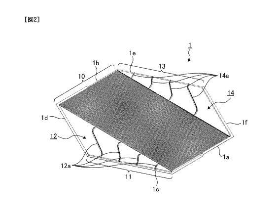
[0013] FIG. 2 is a perspective view illustrating one of
the first partition plates 1 of the heat-exchange element
100 according to the present embodiment. FIG. 2
illustrates a state where the heat-exchange element 100 is
viewed from the same direction as in FIG. 1. The first
partition plate 1 includes a first counter-flow portion 10
as a heat-exchange portion, a first inlet 11, a first
header portion 12 that is a portion connecting the first
inlet 11 and the first counter-flow portion 10, a first
outlet 13, and a second header portion 14 that is a portion
connecting the first outlet 13 and the first counter-flow
portion 10. The first partition plate 1 includes six edges
la, lb, lc, id, le, and if. The first counter-flow portion
10 is formed in a region sandwiched between the first edge
la and the second edge lb. The third edge lc and the
fourth edge id are disposed, for example, on one side of
the first edge la and the second edge lb. The fifth edge
le and the sixth edge lf are disposed, for example, on the
opposite side of the first edge la and the second edge lb.
The first header portion 12 in a triangular shape is
disposed in a region enclosed by the third edge lc, the
fourth edge id, and the first counter-flow portion 10. The
second header portion 14 in a triangular shape is disposed
in a region enclosed by the fifth edge le, the sixth edge
if, and the first counter-flow portion 10.
[0014] Six edge portions of the first partition plate 1
are formed such that openings are formed only at the
portion of the third edge lc corresponding to the first
inlet 11 and the portion of the fifth edge le corresponding
to the first outlet 13, and the portions of the first edge
Date Recue/Date Received 2022-12-28
CA 03188445 2022-12-28
Docket No. PMDA-22130-US,EP,CA,CN, Status: Final
9
la, the second edge lb, the fourth edge id, and the sixth
edge if are closed when the second partition plate 2 is
placed thereon. That is, the portions of the first edge
la, the second edge lb, the fourth edge id, and the sixth
edge if are formed, for example, in a rising shape to be
closed. In the first partition plate 1 illustrated in FIG.
2, a part (about a half in the illustration) of the first
edge is adjacent to the third edge lc is not formed in the
rising shape to form an opening. Likewise, a part (about a
half in the illustration) of the second edge lb adjacent to
the fifth edge le is not formed in the rising shape to form
an opening. Furthermore, in a corner area of the first
counter-flow portion 10 with the point of intersection of
the first edge la and the third edge lc as the corner, a
corrugated body 10a as the heat-exchange portion to be
described later is not formed. Likewise, in a corner area
of the first counter-flow portion 10 with the point of
intersection of the second edge lb and the fifth edge le as
the corner, the corrugated body 10a as the heat-exchange
portion to be described later is not formed.
[0015] The first counter-flow portion 10 includes a
plurality of flow paths extending in parallel to the first
edge la and the second edge lb. The plurality of flow
paths formed in the first counter-flow portion 10
correspond to third flow paths in the claims. FIG. 4 is a
partial cross-sectional view illustrating an example of the
first counter-flow portion 10. FIG. 4 illustrates a cross-
sectional view with the first edge la and the second edge
lb cut perpendicularly. The first counter-flow portion 10
includes the corrugated body 10a having a corrugated shape
in which recesses and protrusions are formed alternately
and continuously. The plurality of flow paths in the first
counter-flow portion 10 as the heat-exchange portion is not
Date Recue/Date Received 2022-12-28
CA 03188445 2022-12-28
Docket No. PMDA-22130-US,EP,CA,CN, Status: Final
limited to the structure of FIG. 4 and may adopt other
structures as long as a plurality of flow paths extending
in parallel to the first edge la and the second edge lb are
formed.
5 [0016] As illustrated in FIG. 2, a plurality of
protruded first ribs 12a are formed at intervals on the
first header portion 12. A plurality of protruded second
ribs 14a are formed at intervals on the second header
portion 14. The first ribs 12a and the second ribs 14a are
10 formed by press working, vacuum forming, or the like.
[0017] The plurality of first ribs 12a extend from the
third edge lc along the fourth edge id toward the first
counter-flow portion 10. Each of the plurality of first
ribs 12a has an S shape. The closer to the fourth edge id
the first ribs 12a are, the longer their lengths are. The
plurality of second ribs 14a extend from the fifth edge le
along the sixth edge if toward the first counter-flow
portion 10. Each of the plurality of second ribs 14a has
an S shape. The closer to the sixth edge if the second
ribs 14a are, the longer their lengths are. Details of the
first ribs 12a and the second ribs 14a will be described
later.
[0018] FIG. 3 is a perspective view illustrating one of
the second partition plates 2 of the heat-exchange element
100 according to the embodiment. FIG. 3 illustrates a
state where the heat-exchange element 100 is viewed from
the same direction as in FIG. 1. The second partition
plate 2 includes a second counter-flow portion 20 as a
heat-exchange portion, a second inlet 21, a fourth header
portion 22 that is a portion connecting the second inlet 21
and the second counter-flow portion 20, a second outlet 23,
and a third header portion 24 that is a portion connecting
the second outlet 23 and the second counter-flow portion
Date Recue/Date Received 2022-12-28
CA 03188445 2022-12-28
Docket No. PMDA-22130-US,EP,CA,CN, Status: Final
11
20. The second partition plate 2 includes six edges 2a,
2b, 2c, 2d, 2e, and 2f. The second counter-flow portion 20
is formed in a region sandwiched between the seventh edge
2a and the eighth edge 2b. The ninth edge 2c and the tenth
edge 2d are disposed, for example, on one side of the
seventh edge 2a and the eighth edge 2b. The eleventh edge
2e and the twelfth edge 2f are disposed, for example, on
the opposite side of the seventh edge 2a and the eighth
edge 2b. The third header portion 24 in a triangular shape
is disposed in a region enclosed by the ninth edge 2c, the
tenth edge 2d, and the second counter-flow portion 20. The
fourth header portion 22 in a triangular shape is disposed
in a region enclosed by the eleventh edge 2e, the twelfth
edge 2f, and the second counter-flow portion 20.
[0019] Six edge
portions of the second partition plate 2
are formed such that openings are formed only at the
portion of the twelfth edge 2f corresponding to the second
inlet 21 and the portion of the tenth edge 2d corresponding
to the second outlet 23, and the portions of the seventh
edge 2a, the eighth edge 2b, the ninth edge 2c, and the
eleventh edge 2e are closed when the first partition plate
1 is placed thereon. That is, the portions of the seventh
edge 2a, the eighth edge 2b, the ninth edge 2c, and the
eleventh edge 2e are formed, for example, in a rising shape
to be closed. In the second partition plate 2 illustrated
in FIG. 3, a part (about a half in the illustration) of the
seventh edge 2a adjacent to the twelfth edge 2f is not
formed in the rising shape to form an opening. Likewise, a
part (about a half in the illustration) of the eighth edge
2b adjacent to the tenth edge 2d is not formed in the
rising shape to form an opening. Furthermore, in a corner
area of the second counter-flow portion 20 with the point
of intersection of the seventh edge 2a and the twelfth edge
Date Recue/Date Received 2022-12-28
CA 03188445 2022-12-28
Docket No. PMDA-22130-US,EP,CA,CN, Status: Final
12
2f as the corner, a corrugated body 20a as the heat-
exchange portion to be described later is not formed.
Likewise, in a corner area of the second counter-flow
portion 20 with the point of intersection of the eighth
edge 2b and the tenth edge 2d as the corner, the corrugated
body 20a as the heat-exchange portion to be described later
is not formed.
[0020] The second counter-flow portion 20 includes a
plurality of flow paths extending in parallel to the
seventh edge 2a and the eighth edge 2b. The plurality of
flow paths formed in the second counter-flow portion 20
correspond to fourth flow paths in the claims. As
illustrated in FIG. 4, the second counter-flow portion 20
includes the corrugated body 20a having a corrugated shape
in which recesses and protrusions are formed alternately
and continuously. The plurality of flow paths in the
second counter-flow portion 20 as the heat-exchange portion
is not limited to the structure of FIG. 4 and may adopt
other structures as long as a plurality of flow paths
extending in parallel to the seventh edge 2a and the eighth
edge 2b are formed.
[0021] As illustrated in FIG. 3, a plurality of
protruded third ribs 24a are formed at intervals on the
third header portion 24. A plurality of protruded fourth
ribs 22a are formed at intervals on the fourth header
portion 22. The third ribs 24a and the fourth ribs 22a are
formed by press working, vacuum forming, or the like.
[0022] The plurality of third ribs 24a extend from the
tenth edge 2d along the ninth edge 2c toward the second
counter-flow portion 20. Each of the plurality of third
ribs 24a has an inverted S shape. The closer to the ninth
edge 2c the third ribs 24a are, the longer their lengths
are. The plurality of fourth ribs 22a extend from the
Date Recue/Date Received 2022-12-28
CA 03188445 2022-12-28
Docket No. PMDA-22130-US,EP,CA,CN, Status: Final
13
twelfth edge 2f along the eleventh edge 2e toward the
second counter-flow portion 20. Each of the plurality of
fourth ribs 22a has an inverted S shape. The closer to the
eleventh edge 2e the fourth ribs 22a are, the longer their
lengths are. Details of the third ribs 24a and the fourth
ribs 22a will be described later.
[0023] In the heat-exchange element 100 according to the
embodiment, the first partition plates 1 and the second
partition plates 2 are stacked alternately such that the
first edge la is placed on the seventh edge 2a, and the
third edge lc is placed on the ninth edge 2c. More
specifically, furthermore, the second edge lb is placed on
the eighth edge 2b, the fourth edge id is placed on the
tenth edge 2d, the fifth edge le is placed on the eleventh
edge 2e, and the sixth edge if is placed on the twelfth
edge 2f.
[0024] By placing the first partition plates 1 and the
second partition plates 2 on top of each other, the first
inlet 11 is formed between the third edge lc of the first
partition plate 1 and the ninth edge 2c of the second
partition plate 2. The first outlet 13 is formed between
the fifth edge le of the first partition plate 1 and the
eleventh edge 2e of the second partition plate 2. The
second inlet 21 is formed between the twelfth edge 2f of
the second partition plate 2 and the sixth edge if of the
first partition plate 1. The second outlet 23 is formed
between the tenth edge 2d of the second partition plate 2
and the fourth edge id of the first partition plate 1.
[0025] Further, by placing the first partition plates 1
and the second partition plates 2 on top of each other, the
first flow paths indicated by the arrows Fl, F2, F3, F4,
and F5 illustrated in FIG. 1 are formed by the first ribs
12a, the plurality of flow paths in the first counter-flow
Date Recue/Date Received 2022-12-28
CA 03188445 2022-12-28
Docket No. PMDA-22130-US,EP,CA,CN, Status: Final
14
portion 10, and the second ribs 14a. Furthermore, the
second flow paths indicated by the arrows Gl, G2, G3, G4,
and G5 illustrated in FIG. 1 are formed by the fourth ribs
22a, the plurality of flow paths in the second counter-flow
portion 20, and the third ribs 24a.
[0026] As indicated by the arrows Fl, F2, F3, F4, and F5
illustrated in FIG. 1, air flown into the first inlet 11 is
changed in flow direction to the first counter-flow portion
in the first header portion 12 and passes through the
10 first counter-flow portion 10, and is changed in flow
direction to the first outlet 13 in the second header
portion 14 and is discharged from the first outlet 13. As
indicated by the arrows G1, G2, G3, G4, and G5 illustrated
in FIG. 1, air flown into the second inlet 21 is changed in
flow direction to the second counter-flow portion 20 in the
fourth header portion 22 and passes through the second
counter-flow portion 20, and is changed in flow direction
to the second outlet 23 in the third header portion 24 and
is discharged from the second outlet 23. In a portion
where the first counter-flow portion 10 is placed on the
second counter-flow portion 20, air flows in opposite
directions, facing each other, and heat exchange is
performed between two fluids.
[0027] The first inlet 11, the plurality of first ribs
12a, the plurality of flow paths in the first counter-flow
portion 10, the plurality of second ribs 14a, and the first
outlet 13, and the second outlet 23, the plurality of third
ribs 24a, the plurality of flow paths in the second
counter-flow portion 20, the plurality of fourth ribs 22a,
and the second inlet 21 are arranged such that the first
flow paths indicated by the arrows Fl, F2, F3, F4, and F5
and the second flow paths indicated by the arrows Gl, G2,
G3, G4, and G5 illustrated in FIG. 1 are symmetrical about
Date Recue/Date Received 2022-12-28
CA 03188445 2022-12-28
Docket No. PMDA-22130-US,EP,CA,CN, Status: Final
an axis that connects the point of intersection of the
fifth edge le and the sixth edge if of the first partition
plate 1 and the point of intersection of the third edge lc
and the fourth edge id of the first partition plate 1.
5 [0028] FIG. 5 is a plan view illustrating an arrangement
of the plurality of first ribs 12a of the first header
portion 12 that is an inlet-side header. The fourth header
portion 22 has the same arrangement. The plurality of
first ribs 12a extend in different directions. Of the
10 plurality of first ribs 12a, the extending direction of a
rib far from the fourth edge id adjacent to the first inlet
11 is closer to the extending direction F3 of the flow
paths in the first counter-flow portion 10 than the
extending direction of a rib close to the fourth edge ld.
15 That is, the angle formed by the extending direction of the
first rib 12a close to the fourth edge id and the extending
direction F3 of the flow paths in the first counter-flow
portion 10 is smaller than the angle formed by the
extending direction of the first rib 12a far from the
fourth edge id and the extending direction F3 of the flow
paths in the first counter-flow portion 10. In other
words, the extending directions of the plurality of first
ribs 12a of the first header portion 12 become closer to
the extending direction F3 of the flow paths in the first
counter-flow portion 10 with increasing distance from the
fourth edge id. Consequently, in the first header portion
12, the flow path widths of the plurality of flow paths
formed by the plurality of first ribs 12a are larger near
the first counter-flow portion 10 than near the first inlet
11.
[0029] The extending directions of the four first ribs
12a illustrated in FIG. 5 are represented by angles 01 to
04 with respect to the fourth edge id. 81 is the angle of
Date Recue/Date Received 2022-12-28
CA 03188445 2022-12-28
Docket No. PMDA-22130-US,EP,CA,CN, Status: Final
16
the first rib 12a closest to the fourth edge ld, 02 is the
angle of the first rib 12a second closest to the fourth
edge id, e3 is the angle of the first rib 12a third closest
to the fourth edge 1d, and 04 is the angle of the first rib
12a farthest from the fourth edge 1d. The relationship
01<02<03<04 is established among the plurality of first
ribs 12a.
[0030] FIG. 6 is a plan view for explaining, in more
detail, end shapes and others of the plurality of first
ribs 12a of the first header portion 12. Each first rib
12a is composed of an upstream rib 120, a middle rib 121,
and a downstream rib 122. The middle rib 121 has a linear
shape. The upstream rib 120 has a curved shape that is a
single-R shape formed by one arc. The single-R shapes of
the upstream ribs 120 of the plurality of first ribs 12a
all have the same radius.
[0031] Each downstream rib 122 has a curved shape that
is a single-R shape formed by one arc. The single-R shapes
of the downstream ribs 122 of the plurality of first ribs
12a individually have different radii. The radii of the
downstream ribs 122 of the plurality of first ribs 12a
increase in curvature with increasing distance from the
fourth edge id.
[0032] When attention is paid to the upstream rib 120
and the downstream rib 122 of one of the first ribs 12a,
the curvature of the upstream rib 120 is set to be larger
than the curvature of the downstream rib 122.
[0033] As described above, the overall shape of the
first ribs 12a is almost an S shape including a straight
line, in other words, the shape of a letter S elongated
lengthwise. The extending directions of the first ribs 12a
described above are represented by the extending directions
of the middle ribs 121.
Date Recue/Date Received 2022-12-28
CA 03188445 2022-12-28
Docket No. PMDA-22130-US,EP,CA,CN, Status: Final
17
[ 0 0 3 4 ] The angular differences between the direction of
the upstream ends of the upstream ribs 120 and the
direction of the downstream ends of the downstream ribs 122
and the extending direction F3 of the flow paths in the
first counter-flow portion 10 are smaller than the angular
differences between the directions of the middle ribs 121
and the extending direction F3. Specifically, the upstream
ends of the upstream ribs 120 are almost perpendicular to
the third edge lc constituting the first inlet 11.
[0035] The direction of the downstream end of each
downstream rib 122 is at an angle nearly parallel to the
extending direction F3 of the flow paths in the first
counter-flow portion 10. The relationship between each
downstream rib 122 and the flow paths in the first counter-
flow portion 10 will be described in more detail with
reference to FIG. 7. FIG. 7 is a plan view illustrating a
positional relationship between the downstream rib 122 and
the flow paths in the first counter-flow portion 10. As
illustrated in FIG. 7, the downstream end of the downstream
rib 122 does not extend to the first counter-flow portion
10, and faces the upstream edge of the first counter-flow
portion 10 across a gap L.-L. A virtual extension line 125
of the single-R shape of the downstream rib 122 touches a
straight line indicating the extending direction F3 of the
flow paths in the first counter-flow portion 10.
[0036] The upstream ribs 120 and the downstream ribs
122, which have been illustrated with the examples of the
single-R arc shapes, may each have a curved shape that
combines arcs having different radii R. The middle ribs
121, which have been illustrated with the example of the
linear shape, may each have a slight curve as long as they
are almost linear as a whole.
[0037] Next, the plurality of second ribs 14a of the
Date Recue/Date Received 2022-12-28
CA 03188445 2022-12-28
Docket No. PMDA-22130-US,EP,CA,CN, Status: Final
18
second header portion 14 that is an outlet-side header will
be described with reference to FIGS. 8 and 9. FIG. 8 is a
plan view illustrating an arrangement of the plurality of
second ribs 14a of the second header portion 14. The third
header portion 24 has the same arrangement. The plurality
of second ribs 14a extend in different directions. Of the
plurality of second ribs 14a, the extending direction of a
rib far from the sixth edge if adjacent to the first outlet
13 is closer to the extending direction F3 of the flow
paths in the first counter-flow portion 10 than the
extending direction of a rib close to the sixth edge if.
That is, the angle formed by the extending direction of the
second rib 14a close to the sixth edge if and the extending
direction F3 of the flow paths in the first counter-flow
portion 10 is smaller than the angle formed by the
extending direction of the second rib 14a far from the
sixth edge if and the extending direction F3 of the flow
paths in the first counter-flow portion 10. In other
words, the extending directions of the plurality of second
ribs 14a of the second header portion 14 become closer to
the extending direction F3 of the flow paths in the first
counter-flow portion 10 with increasing distance from the
sixth edge if. Consequently, in the second header portion
14, the flow path widths of the plurality of flow paths
formed by the plurality of second ribs 14a are larger near
the first counter-flow portion 10 than near the first
outlet 13.
[0038] The extending directions of the four second ribs
14a illustrated in FIG. 8 are represented by angles p1 to
p4 with respect to the sixth edge if. p1 is the angle of
the second rib 14a closest to the sixth edge if, 92 is the
angle of the second rib 14a second closest to the sixth
edge if, p3 is the angle of the second rib 14a third
Date Recue/Date Received 2022-12-28
CA 03188445 2022-12-28
Docket No. PMDA-22130-US,EP,CA,CN, Status: Final
19
closest to the sixth edge if, and (p4 is the angle of the
second rib 14a farthest from the sixth edge if. The
relationship p1<p2<93<p4 is established among the plurality
of second ribs 14a.
[0039] FIG. 9 is a plan view for explaining, in more
detail, end shapes and others of the plurality of second
ribs 14a of the second header portion 14. Each second rib
14a is composed of a downstream rib 140, a middle rib 141,
and an upstream rib 142. The middle rib 141 has a linear
shape. The downstream rib 140 has a curved shape that is a
single-R shape formed by one arc. The single-R shapes of
the downstream ribs 140 of the plurality of second ribs 14a
all have the same radius.
[0040] Each upstream rib 142 has a curved shape that is
a single-R shape formed by one arc. The single-R shapes of
the upstream ribs 142 of the plurality of second ribs 14a
individually have different radii. The radii of the
upstream ribs 142 of the plurality of second ribs 14a
increase in curvature with increasing distance from the
sixth edge if.
[0041] When attention is paid to the downstream rib 140
and the upstream rib 142 of one second rib 14a, the
curvature of the downstream rib 140 is set to be larger
than the curvature of the upstream rib 142.
[0042] Thus, the overall shape of the second ribs 14a is
almost an S shape including a straight line, in other
words, the shape of a letter S elongated lengthwise. The
extending directions of the second ribs 14a described above
are represented by the extending directions of the middle
ribs 141.
[0043] The angular differences between the direction of
the downstream ends of the downstream ribs 140 and the
direction of the upstream ends of the upstream ribs 142 and
Date Recue/Date Received 2022-12-28
CA 03188445 2022-12-28
Docket No. PMDA-22130-US,EP,CA,CN, Status: Final
the extending direction F3 of the flow paths in the first
counter-flow portion 10 are smaller than the angular
differences between the directions of the middle ribs 141
and the extending direction F3. Specifically, the
5 downstream ends of the downstream ribs 140 are almost
perpendicular to the fifth edge le constituting the first
outlet 13.
[0044] The direction of the upstream end of each
upstream rib 142 is at an angle nearly parallel to the
10 extending direction F3 of the flow paths in the first
counter-flow portion 10. Like the downstream rib 122 of
the first rib 12a illustrated in FIG. 7, the upstream end
of each upstream rib 142 does not extend to the first
counter-flow portion 10, and faces the downstream edge of
15 the first counter-flow portion 10 across a gap. A virtual
extension line of the single-R shape of each upstream rib
142 touches a straight line indicating the extending
direction F3 of the flow paths in the first counter-flow
portion 10.
20 [0045] The downstream ribs 140 and the upstream ribs
142, which have been illustrated with the examples of the
single-R arc shapes, may each have a curved shape that
combines arcs having different radii R. The middle ribs
141, which have been illustrated with the example of the
linear shape, may each have a slight curve as long as they
are almost linear as a whole.
[0046] FIG. 10 is a diagram illustrating an air velocity
distribution in a header portion with a rib arrangement
according to a comparative example. In the comparative
example, an air velocity distribution in a portion
corresponding to the first header portion 12 is
illustrated. A plurality of ribs 50 are arranged in
parallel to each other. The flow path widths between the
Date Recue/Date Received 2022-12-28
CA 03188445 2022-12-28
Docket No. PMDA-22130-US,EP,CA,CN, Status: Final
21
ribs 50 are equal intervals along the entire lengths of the
ribs 50. In the comparative example, portions of the ribs
50 corresponding to the upstream ribs are not formed in an
arc shape. In the comparative example, flow stagnation 43
occurs at each rib 50, which is a cause of pressure loss.
[0047] FIG. 11 is a diagram illustrating an air velocity
distribution in the first header portion 12 with the rib
arrangement according to the present embodiment. In FIG.
11, in order to confirm the respective effects of the angle
and the end shape of each rib, the upstream rib 120 of each
first rib 12a is not formed in an arc shape, and the rib
angles of the first ribs 12a are set such that the above-
described relationship el<02<03<04 is established. In the
case of FIG. 11, stagnation 44 occurs only at the first rib
12a closest to the fourth edge 1d due to the small rib
collision angle of an inflow air current, but stagnation
disappears at the other first ribs 12a. Furthermore, by
setting 01<02<03<04, the air velocity distribution in the
vicinity of the first counter-flow portion 10 is not
affected, and heat-exchange efficiency is not hindered.
[0048] FIG. 12 is a diagram illustrating an air velocity
distribution in the first header portion 12 with the rib
arrangement according to the present embodiment. In FIG.
12, in order to confirm the respective effects of the angle
and the end shape of each rib, the first ribs 12a are made
the same in rib angle as in the comparative example, and
the upstream rib 120 of each first rib 12a is formed in an
arc shape. In the case of FIG. 12, air flows along the
ribs at all the first ribs 12a, and stagnation disappears.
However, at the two first ribs 12a far from the fourth edge
ld, stagnation 45 occurs in flow, compared to the
distribution around the ribs at the same places in FIG. 11.
The stagnation 45 can be eliminated by setting the rib
Date Recue/Date Received 2022-12-28
CA 03188445 2022-12-28
Docket No. PMDA-22130-US,EP,CA,CN, Status: Final
22
angles to 01<e2<03<04 as illustrated in FIG. 11.
[0049] Thus, according to the embodiment, the plurality
of ribs on each header portion are formed to establish the
relationship e1<02<e3<e4 or the relationship p1<p2<93<94.
Consequently, in the header portion, the flow path widths
of the plurality of flow paths formed by the plurality of
ribs are larger near the counter-flow portion than near the
inlet. This can reduce pressure loss in the header portion
and allows air currents to uniformly flow into the counter-
flow portion.
[0050] In this embodiment, the upstream ribs of the
inlet-side header are formed in an arc shape so that the
upstream ends of the upstream ribs are perpendicular to the
edge constituting the inlet. Consequently, the inflow
direction of an air current at the inlet agrees with the
direction of the upstream ribs of the inlet-side header,
reducing pressure loss at the inlet. The downstream ribs
of the outlet-side header are formed in an arc shape so
that the downstream ends of the downstream ribs are
perpendicular to the edge constituting the outlet.
Consequently, the outflow direction of an air current at
the outlet agrees with the direction of the downstream ribs
of the outlet-side header, reducing pressure loss at the
outlet.
[0051] In this embodiment, the extending directions of
the upstream ribs are made closer to the extending
direction of the flow paths in the counter-flow portion
than the extending directions of the middle ribs, and the
extending directions of the downstream ribs are made closer
to the extending direction of the flow paths in the
counter-flow portion than the extending directions of the
middle ribs. This can reduce pressure loss in the header
portions.
Date Recue/Date Received 2022-12-28
CA 03188445 2022-12-28
Docket No. PMDA-22130-US,EP,CA,CN, Status: Final
23
[ 0052] In this embodiment, the downstream end of the
downstream rib 122 of each first rib 12a faces the upstream
edge of the first counter-flow portion 10 across the gap
At, the downstream rib 122 of each first rib 12a has an arc
shape, the virtual extension line 125 of the downstream rib
122 of each first rib 12a touches the extending direction
F3 of the flow paths in the first counter-flow portion 10,
the upstream end of the upstream rib 142 of each second rib
14a faces the downstream edge of the first counter-flow
portion 10 across the gap, the upstream rib 142 of each
second rib 14a has an arc shape, and the virtual extension
line of the upstream rib 142 of each second rib 14a touches
the extending direction F3 of the flow paths in the first
counter-flow portion 10. This can reduce pressure loss in
flows from the first ribs 12a to the first counter-flow
portion 10 and flows from the first counter-flow portion 10
to the second ribs 14a.
[0053] The downstream ribs 122 of the plurality of first
ribs 12a of the first header portion 12 have arc shapes of
different radii and increase in curvature with increasing
distance from the fourth edge id, and the upstream ribs 142
of the plurality of second ribs 14a of the second header
portion 14 have arc shapes of different radii and increase
in curvature with increasing distance from the sixth edge
if. This achieves uniform flows from the first ribs 12a to
the first counter-flow portion 10 and achieves uniform
flows from the first counter-flow portion 10 to the second
ribs 14a.
[0054] When the heat-exchange element 100 in FIG. 1 is
viewed as a plan view, in the heat-exchange element 100 in
FIG. 1, the first partition plates 1 form the first flow
paths from the lower left to the upper right, and the
second partition plates 2 form the second flow paths from
Date Recue/Date Received 2022-12-28
CA 03188445 2022-12-28
Docket No. PMDA-22130-US,EP,CA,CN, Status: Final
24
the lower right to the upper left. In another embodiment,
the first partition plates 1 may form the first flow paths
from the upper left to the lower right, and the second
partition plates 2 may form the second flow paths from the
upper right to the lower left, or the first partition
plates 1 may form the first flow paths from the lower right
to the upper left, and the second partition plates 2 may
form the second flow paths from the lower left to the upper
right, or the first partition plates I may form the first
flow paths from the upper right to the lower left, and the
second partition plates 2 may form the second flow paths
from the upper left to the lower right.
[0055] Next, a heat-exchange ventilation apparatus 200
including the heat-exchange element 100 will be described.
FIG. 13 is a conceptual diagram illustrating the heat-
exchange ventilation apparatus 200 in which the heat-
exchange element 100 is installed.
[0056] The heat-exchange ventilation apparatus 200
includes an air supply fan 214, an air exhaust fan 215, the
heat-exchange element 100, and a casing 213.
[0057] The casing 213 is a box-shaped member that houses
the air supply fan 214, the air exhaust fan 215, and the
heat-exchange element 100. A supply air passage 216
through which a first air current 207 passes and an exhaust
air passage 217 through which a second air current 208
passes are provided in the casing 213. The first air
current 207 is a supply air current from the outside to the
inside of a room. The second air current 208 is an exhaust
air current from the inside to the outside of the room. A
supply air outlet 220 and an exhaust air inlet 219 are
provided in an interior-side side surface of the casing
213. A supply air inlet 218 and an exhaust air outlet 221
are provided in an exterior-side side surface of the casing
Date Recue/Date Received 2022-12-28
CA 03188445 2022-12-28
Docket No. PMDA-22130-US,EP,CA,CN, Status: Final
213.
[0058] The air supply fan 214 is disposed in the supply
air passage 216. The air supply fan 214 takes outside air
from the supply air inlet 218 into the supply air passage
5 216, generating the first air current 207. The first air
current 207 flows through the supply air passage 216 and is
blown into the room from the supply air outlet 220. The
air supply fan 214 generates the first air current 207 from
the outside to the inside of the room.
10 [0059] The air exhaust fan 215 is disposed in the
exhaust air passage 217. The air exhaust fan 215 takes
inside air from the exhaust air inlet 219 into the exhaust
air passage 217, generating the second air current 208.
The second air current 208 flows through the exhaust air
15 passage 217 and is blown to the outside of the room from
the exhaust air outlet 221. The air exhaust fan 215
generates the second air current 208 from the inside to the
outside of the room.
[0060] The heat-exchange element 100 is provided at the
20 position of the intersection of the supply air passage 216
and the exhaust air passage 217. The heat-exchange element
100 performs total heat exchange between the first air
current 207 flowing through the supply air passage 216 and
the second air current 208 flowing through the exhaust air
25 passage 217. The heat-exchange ventilation apparatus 200
recovers sensible heat and latent heat of an exhaust air
current from inside the room by total heat exchange in the
heat-exchange element 100, and transfers the recovered
sensible heat and latent heat to a supply air current.
Further, the heat-exchange ventilation apparatus 200
recovers sensible heat and latent heat of a supply air
current from outside the room by total heat exchange in the
heat-exchange element 100, and transfers the recovered
Date Recue/Date Received 2022-12-28
CA 03188445 2022-12-28
90247809
26
sensible heat and latent heat to an exhaust air current.
The heat-exchange ventilation apparatus 200 can improve
cooling and heating efficiency and dehumidification and
humidification efficiency in the room, reducing energy used
for air conditioning in the room. The heat-exchange element
100 may be configured to transfer only sensible heat between
an exhaust air current and a supply air current.
[0061] The configuration described in the above
embodiment illustrates an example of the subject matter of
the present disclosure, and can be combined with another
known art, and can be partly omitted or changed without
departing from the scope of the present disclosure.
Reference Signs List
[0062] 1 first partition plate; la first edge; lb
second edge; lc third edge; id fourth edge; le fifth
edge; if sixth edge; 2 second partition plate; 2a seventh
edge; 2b eighth edge; 2c ninth edge; 2d tenth edge; 2e
eleventh edge; 2f twelfth edge; 10 first counter-flow
portion; 11 first inlet; 12 first header portion; 12a
first rib; 13 first outlet; 14 second header portion; 14a
second rib; 20 second counter-flow portion; 21 second
inlet; 22 fourth header portion; 22a fourth rib; 23
second outlet; 24 third header portion; 24a third rib; 100
heat-exchange element; 120, 142 upstream rib; 121, 141
middle rib; 122, 140 downstream rib; 200 heat-exchange
ventilation apparatus.
Date Recue/Date Received 2022-12-28