Note: Descriptions are shown in the official language in which they were submitted.
SKATE
FIELD
The invention generally relates to skates (e.g., ice skates), such as for
playing
hockey and/or for other activities.
BACKGROUND
Skates are used by users in various sports such as ice hockey, roller hockey,
etc.
and other skating activities.
A skate comprises a skate boot that typically comprises a number of components
that are assembled together to form the skate boot. This can include a shell,
a toe
cap, a tongue, a tendon guard, etc. In some cases, this may entail numerous
operations to make the skate boot, which may be impractical, inefficient
and/or
costly.
For these and/or other reasons, there is a need for improvements directed to
skates.
SUMMARY
In accordance with various aspects of the invention, there is provided a skate
(e.g.,
an ice skate) for a user. The skate comprises a skate boot for receiving a
foot of the
user and a skating device (e.g., a blade and a blade holder) disposed beneath
the
skate boot to engage a skating surface. The skate boot may be constructed by
molding (e.g., injection molding) so as to have useful performance and/or
other
characteristics (e.g., reduced weight; enhanced fit, comfort and range of
motion;
enhanced appearance; etc.) while being cost-effectively manufactured.
Date Recue/Date Received 2023-02-06
For example, in accordance with an aspect of the invention, there is provided
a
skate. The skate comprises a skate boot defining a cavity to receive a foot of
a user.
The skate boot comprises a monolithic body comprising an ankle portion to
receive
an ankle of the user, a heel portion to receive a heel of the user's foot, a
medial side
portion to face a medial side of the user's foot, a lateral side portion to
face a lateral
side of the user's foot, a sole portion to face a plantar surface of the
user's foot, and
a toe portion to enclose toes of the user's foot. The monolithic body is
injection
molded such that the ankle portion, the heel portion, the medial side portion,
the
lateral side portion, the sole portion, and the toe portion are injection
molded
together and integral with one another. The skate boot also comprises lacing
holes
to receive a lace and extending through the monolithic body. The skate also
comprises a skating device disposed beneath the skate boot to engage a skating
surface.
In accordance with another aspect of the invention, there is provided a skate.
The
skate comprises a skate boot defining a cavity to receive a foot of a user.
The skate
boot comprises a monolithic body comprising an ankle portion to receive an
ankle of
the user, a heel portion to receive a heel of the user's foot, a medial side
portion to
face a medial side of the user's foot, a lateral side portion to face a
lateral side of the
user's foot, a sole portion to face a plantar surface of the user's foot, and
a toe
portion to enclose toes of the user's foot. The monolithic body is injection
molded
such that the ankle portion, the heel portion, the medial side portion, the
lateral side
portion, the sole portion, and the toe portion are injection molded together
and
integral with one another. An upper part of the monolithic body is stiffer
than a lower
part of the monolithic body to facilitate forward flex of the user's ankle and
facilitate
tightening of the medial side portion and lateral side portion about an instep
of the
user's foot. The skate boot also comprises lacing holes to receive a lace and
extending through the monolithic body. The skate also comprises a skating
device
disposed beneath the skate boot to engage a skating surface.
2
Date Regue/Date Received 2023-02-06
In accordance with another aspect of the invention, there is provided an ice
skate.
The ice skate comprises a skate boot defining a cavity to receive a foot of a
user.
The skate boot comprises a monolithic body comprising an ankle portion to
receive
an ankle of the user, a heel portion to receive a heel of the user's foot, a
medial side
portion to face a medial side of the user's foot, a lateral side portion to
face a lateral
side of the user's foot, a sole portion to face a plantar surface of the
user's foot, and
a toe portion to enclose toes of the user's foot. The monolithic body is
injection
molded such that the ankle portion, the heel portion, the medial side portion,
the
lateral side portion, the sole portion, and the toe portion are injection
molded
together and integral with one another. A thickness of the monolithic body
varies.
The skate boot also comprises lacing holes to receive a lace and extending
through
the monolithic body. The ice skate also comprises a blade holder and a blade
held
by the blade holder to engage ice.
In accordance with another aspect of the invention, there is provided a skate
boot for
a skate. The skate comprises a skating device disposed beneath the skate boot
to
engage a skating surface. The skate boot defines a cavity to receive a foot of
a user
and comprises a monolithic body comprising an ankle portion to receive an
ankle of
the user, a heel portion to receive a heel of the user's foot, a medial side
portion to
zo face a medial side of the user's foot, a lateral side portion to face a
lateral side of the
user's foot, a sole portion to face a plantar surface of the user's foot, and
a toe
portion to enclose toes of the user's foot. The monolithic body is injection
molded
such that the ankle portion, the heel portion, the medial side portion, the
lateral side
portion, the sole portion, and the toe portion are injection molded together
and
integral with one another. The skate boot also comprises lacing holes to
receive a
lace and extending through the monolithic body.
In accordance with another aspect of the invention, there is provided a skate
boot for
a skate. The skate comprises a skating device disposed beneath the skate boot
to
engage a skating surface. The skate boot defines a cavity to receive a foot of
a user
and comprises a body comprising an ankle portion to receive an ankle of the
user, a
3
Date Regue/Date Received 2023-02-06
heel portion to receive a heel of the user's foot, a medial side portion to
face a
medial side of the user's foot, and a lateral side portion to face a lateral
side of the
user's foot. The skate boot comprises a texture molded during molding of at
least
part of the body and simulating an appearance of a composite material.
These and other aspects of the invention will now become apparent to those of
ordinary skill in the art upon review of the following description of
embodiments of
the invention in conjunction with the accompanying drawings.
BRIEF DESCRIPTION OF DRAWINGS
A detailed description of embodiments of the invention is provided below, by
way of
example only, with reference to drawings annexed hereto, in which:
Figure 1 is an example of a skate for a user in accordance with an embodiment
of the
invention;
Figure 2 is an exploded view of the skate;
Figures 3 to 5 are perspective views of a body of a skate boot of the skate;
Figure 6 is a block diagram showing a molding process implementing a molding
apparatus to form the body of the skate boot;
Figure 7A is an example of a male mold element of the molding apparatus;
Figure 7B is an example of a variant of the male mold element of the molding
apparatus in accordance with an embodiment of the invention;
Figure 8 is a cross-sectional view of the male mold element and a female mold
element of the molding apparatus;
4
Date Regue/Date Received 2023-02-06
Figure 9 is a lateral side plan view of the body of the skate boot;
Figure 10A is a cross-sectional view of the body of the skate boot taken along
lin IA-
10A of Figure 9;
Figure 10B is a cross-sectional view of the body of the skate boot taken along
lin 13-
10B of Figure 9;
Figure 10C is a cross-sectional view of the body of the skate boot taken along
line
10C-10C of Figure 9;
Figure Ills a side elevation view of the skate;
Figure 12 is a perspective view of part of the body of the skate boot
illustrating part of a
mark;
Figure 13A is a bottom plan view of the body of the skate boot illustrating
positional
markers;
Figures 13B to 13E are bottom plan views of the body of the skate boot
illustrating
variants of the positional markers in accordance with embodiments of the
invention;
Figure 14 is a side elevation view of the skate illustrating various
ornamental elements;
Figure 15 is a perspective view of a tongue of the skate boot;
Figure 16 is a side view of a blade of a skating device of the skate;
Figures 17 to 20 show different examples of embodiments in which the blade is
affixed
to a blade holder of the skating device of the skate;
5
Date Regue/Date Received 2023-02-06
Figure 21 is a cross-sectional view of the blade holder in an embodiment in
which the
blade holder comprises a blade-detachment mechanism;
Figure 22 is a side view of the blade of the skating device;
Figure 23 is a cross-sectional view of the blade taken along line 23-23 of
Figure 22;
Figure 24 is a perspective view of the blade holder; and
Figures 25 and 26 are side and front views of a right foot of the user with an
integument of the foot shown in dotted lines and bones shown in solid lines.
In the drawings, embodiments of the invention are illustrated by way of
example. It is
to be expressly understood that the description and drawings are only for
purposes of
illustration and as an aid to understanding, and are not intended to be a
definition of
the limits of the invention.
DETAILED DESCRIPTION OF EMBODIMENTS
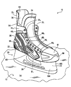
Figure 1 shows an example of a skate 10 for a user to skate on a skating
surface 12, in
accordance with an embodiment of the invention. In this embodiment, the skate
10 is a
hockey skate for the user who is a hockey player playing hockey. In this
example, the
skate 10 is an ice skate, a type of hockey played is ice hockey, and the
skating surface
26 .. 12 is ice 14.
The skate 10 comprises a skate boot 22 for receiving a foot 11 of the player
and a
skating device 28 disposed beneath the skate boot 22 to engage the skating
surface
12. In this embodiment, the skating device 28 comprises a blade 26 for
contacting the
ice 14 and a blade holder 24 between the skate boot 22 and the blade 26. The
skate
10 has a longitudinal direction, a widthwise direction, and a heightwise
direction.
6
Date Regue/Date Received 2023-02-06
In this embodiment, as further discussed below, the skate boot 22 is
constructed by
injection molding so as to have useful performance and/or other
characteristics (e.g.,
reduced weight; enhanced fit, comfort and range of motion; enhanced
appearance;
etc.) while being cost-effectively manufactured.
The skate boot 22 defines a cavity 54 for receiving the player's foot 11. With
additional
reference to Figures 25 and 26, the player's foot 11 includes toes T, a ball
B, an arch
ARC, a plantar surface PS, a top surface TS including an instep IN, a medial
side MS,
and a lateral side LS. The top surface TS of the player's foot 11 is
continuous with a
lower portion of a shin S of the player. In addition, the player has a heel
HL, an Achilles
tendon AT, and an ankle A having a medial malleolus MM and a lateral malleolus
LM
that is at a lower position than the medial malleolus MM. The Achilles tendon
AT has
an upper part UP and a lower part LP projecting outwardly with relation to the
upper
part UP and merging with the heel HL. A forefoot of the player includes the
toes T and
the ball B, a hindfoot of the player includes the heel HL, and a midfoot of
the player is
between the forefoot and the hindfoot.
The skate boot 22 comprises a front portion 56 for receiving the toes T of the
player, a
rear portion 58 for receiving the heel HL and at least part of the Achilles
tendon AT and
the ankle A of the player, and an intermediate portion 60 between the front
portion 56
and the rear portion 58.
More particularly, in this embodiment, with additional reference to Figures 2
to 5, the
skate boot 22 comprises a body 30 and a plurality of components affixed to or
otherwise supported by the body 30, which in this embodiment includes overlays
31 1-
31 N, a tongue 34, a liner 36 and a footbed 38. The skate boot 22 also
comprises lacing
holes 451-45L to receive a lace 47 (shown in Figure 11) and extending through
the
body 30, the liner 36, and the overlays 311, 312 which are medial and lateral
facings,
respectively. In this example, eyelets 461-46E are provided in respective ones
of the
lacing holes 451-45L to engage the lace 47.
7
Date Regue/Date Received 2023-02-06
The body 30 imparts strength and structural integrity to the skate 10 to
support the
player's foot 11. In this embodiment, the body 30 comprises a heel portion 62
for
receiving the heel HL of the player, an ankle portion 64 for receiving the
ankle A of the
player, and medial and lateral side portions 66, 68 for respectively facing
the medial
and lateral sides MS, LS of the player's foot 11. The body 30 thus includes a
quarter 75
which comprises a medial quarter part 77, a lateral quarter part 79, and a
heel quarter
81. The heel portion 62 may be formed such that it is substantially cup-shaped
for
following a contour of the heel HL of the player. The ankle portion 64
comprises medial
and lateral ankle sides 74, 76. The medial ankle side 74 has a medial
depression 78
for receiving the medial malleolus MM of the player and the lateral ankle side
76 has a
lateral depression 80 for receiving the lateral malleolus LM of the player.
The lateral
depression 80 is located slightly lower than the medial depression 78 for
conforming to
the morphology of the player's foot 11. In this example, the body 30 also
comprises a
sole portion 69 for facing the plantar surface PS of the player's foot 11, a
toe portion 61
for enclosing the toes T of the player, and a tendon guard portion 63 for
facing the
upper part UP of the Achilles tendon AT of the player.
In this embodiment, the body 30 is a monolithic body, i.e., a one-piece body
made by
molding (e.g. injection molding), as discussed later.
More particularly, in this embodiment, the monolithic body 30 is injection
molded such
that the ankle portion 64, the heel portion 62, the medial side portion 66,
the lateral side
portion 68, the sole portion 69, the toe portion 61, and the tendon guard
portion 63 are
injection molded together and integral with one another. That is, the ankle
portion 64,
the heel portion 62, the medial side portion 66, the lateral side portion 68,
the sole
portion 69, the toe portion 61, and the tendon guard portion 63 are injection
molded
together as a single piece.
To that end, the monolithic body 30 comprises one or more materials M
injection
molded into a shape of the monolithic body 30 by flowing the one or more
materials in
8
Date Regue/Date Received 2023-02-06
a molding apparatus 150 during an injection molding process, as shown in
Figure 6.
Any suitable material M may be used to make the monolithic body 30. For
example, in
this embodiment, a polymeric material such as polyethylene, polypropylene,
polyurethane (PU), ethylene-vinyl acetate (EVA), nylon, polyester, vinyl,
polyvinyl
chloride, polycarbonate, an ionomer resin (e.g.,.Surlyne), styrene-butadiene
copolymer
(e.g., K-Resin ) etc.), self-reinforced polypropylene composite (e.g., Curve),
glass
reinforced materials and/or any other thermoplastic or thermosetting polymer
may be
used.
Referring additionally to Figures 6, 7A and 8, in this embodiment, the molding
apparatus 150 comprises a mold 151 including a male mold element 152 (which
may
also be referred to as a male form or "last") and a female mold element 154
between
which the one or more materials M are molded to form the monolithic body 30,
with the
female mold element 154 containing the male mold element 152 during the
molding
process. In this embodiment, the female mold element 154 comprises first and
second
portions 155, 157 that are secured together to contain the male mold element
152.
An example of a method for molding the monolithic body 30 by injecting the one
or
more materials M into the molding apparatus 150 will now be described. In
order to
mold the monolithic body 30, the male mold element 152 is secured within the
female
mold element 154 to form a mold cavity 156 between the male mold element 152
and
the female mold element 154. The mold cavity 156 has a shape corresponding to
a
desired shape of the monolithic body 30. The mold cavity 156 is then filled
with one or
more materials M via a sprue, runner and gate system (not shown) of the female
mold
element 154 and left to cure. Upon curing of the one or more materials M for a
sufficient amount of time to form the monolithic body 30, the female mold
element 154
is opened (i.e., its first and second portions 155, 157 are separated from one
another)
and removed from the molding apparatus 150 while the = male mold element 152
remains on the molding apparatus 150 with the monolithic body 30 still on it.
The
monolithic body 30 may then be demolded from (i.e., removed from) the male
mold
element 152. This may be achieved in various ways. For instance, in some
cases, the
9
Date Regue/Date Received 2023-02-06
one or more materials M may have sufficient elasticity to allow an operator of
the
molding apparatus 150 to remove the monolithic body 30 from the male mold
element
152 by flexing the monolithic body 30. In other cases, the monolithic body 30
may be
removed from the male mold element 152 while at least part of the monolithic
body 30
.. has not fully cured such that the monolithic body 30 has some flexibility
that it would
not have if it had fully cured. Moreover, in some cases, the male mold element
152
may be inflatable such that it can be expanded and retracted by controlling a
fluid _
pressure within it. For instance, the inflatable male mold element 152 may be
filled with
air (or any other fluid) to expand it to a "molding" size at which the molding
process is
o .. carried out, and then emptied of air to contract it to a "demolding" size
that is less than
the molding size and at which the demolding of the monolithic body 30 from the
male
, molding element 152 can be carried out. In some cases, the male mold element
152
may comprise a plurality of pieces that may be disassembled to facilitate
removal of
the monolithic body 30 from the male mold element 152.
The monolithic body 30 may be manufactured by injection molding in various
other
ways and other techniques may be used in other embodiments.
In this embodiment, different parts of the monolithic body 30 may vary in
stiffness for fit,
.. comfort, performance, and/or other reasons.
For example, in this embodiment, with additional reference to Figure 9, an
upper part
302 of the monolithic body 30 is stiffer than a lower part 304 of the
monolithic body 30.
In this case, the upper part 302 of the monolithic body 30 is stiffer than the
lower part
.. 304 of the monolithic body 30 to facilitate forward flex of the player's
ankle by opposing
overtightening of the ankle portion 64 about the user's ankle A and facilitate
tightening
of the medial side portion 66 and lateral side portion 68 about the instep IN
of the
player.
.. To that end, in this example, the upper part 302 of the monolithic body 30
includes a
part 73 of the ankle portion 64 and the lower part 304 of the monolithic body
30
Date Regue/Date Received 2023-02-06
includes respective parts 53, 55 of the medial side portion 66 and the lateral
side
portion 68. For instance, the part 73 of the ankle portion 64 that is stiffer
may include
the medial and lateral ankle sides 74 76 of a collar of the ankle portion 64
that
comprises upper ones of the lacing holes 451-45L, and the parts 53, 55 of the
medial
side portion 66 and lateral side portion 68 of the monolithic body 30 are
configured to
overlie the instep IN of the player's foot and include lower ones of the
lacing holes 45i-
45L so that they can be moved more easily closer to the instep IN of the
player's foot
when donning the skate 10.
More particularly, with additional reference to Figures 10A, 10B and 10C, in
this
embodiment, a thickness T of the monolithic body 30 varies to achieve
variations in
stiffness of the monolithic body 30. In this example, the thickness T of the
upper part
302 of the monolithic body 30, which is also denoted TA, is greater than the
thickness T
of the lower part 304 of the monolithic body 30, which is also denoted Tc. For
example,
in some embodiments, a ratio of the thickness TA of the upper part 302 of the
monolithic body 30 over the thickness Tc of the lower part 304 of the
monolithic body
30 may be at least 1.2, in some cases at least 1.3, in some cases at least
1.4, in some
cases at least 1.5, and in some cases even more.
Also, in this embodiment, the thickness TA of the upper part 302 of the
monolithic body
is greater than the thickness T of an intermediate part 306 of the monolithic
body
30, denoted TB, where the intermediate part 306 is located between the upper
part 302
and the lower part 304 of the monolithic body 30 in the heightwise direction
of the skate
10. In this embodiment, the intermediate part 306 of the monolithic body 30 is
located
25 about an upper area of the medial side portion 66 and the lateral side
portion 68
proximate to the ankle portion 64 and the lower part 304 of the monolithic
body 30 is
located about a lower area of the medial side portion 66 and the lateral side
portion 68
proximate to the toe portion 61. In this embodiment, the thickness TB of the
intermediate part 306 of the monolithic body 30 is greater than the thickness
Tc of the
30 lower part 304 of the monolithic body 30.
11
Date Regue/Date Received 2023-02-06
To that end, in this embodiment, both the intermediate part 306 and the lower
part 304
of the monolithic body 30 include respective parts of the medial side portion
66 and the
lateral side portion 68 about the instep IN of the player's foot and the
monolithic body
30 is arranged such that the thickness T of the monolithic body 30 decreases
from the
intermediate part 306 towards the lower part 304 of the monolithic body 30
along the
medial side portion 66 and the lateral side portion 68 about the instep IN of
the player's
foot. In this case, the intermediate part 308 of the monolithic body 30 is
stiffer than the "
lower part 304 of the monolithic body 30. In other embodiments, thickness T of
the
monolithic body 30 may be substantially identical at the intermediate part 306
and the
lower part 304 of the monolithic body 30, resulting in substantially identical
stiffness in
both the lower and intermediate parts 304, 306 of the monolithic body 30.
Although it is illustrated in the embodiments in Figures 10A, 10B and 10C that
the
thickness T of the monolithic body 30 on both the medial and lateral side
portions 66 68
is the same (or similar), in other embodiments, the thickness T of the
monolithic body
30 on the medial side portion 66 of the upper part 302 of the monolithic body
30 may
be different from the thickness T of the monolithic body 30 on the lateral
side portion 68
of the upper part 302 of the monolithic body 30. Likewise, the thickness T of
the
monolithic body 30 on the medial side portion 66 of the lower part 304 of the
monolithic
body 30 may be different from the thickness T of the monolithic body 30 on the
lateral
side portion 68 of the lower part 304 of the monolithic body 30. Similarly,
the thickness
T of the monolithic body 30 on the medial side portion 66 of the intermediate
part 306
of the monolithic body 30 may be different from the thickness T of the
monolithic body
on the lateral side portion 68 of the intermediate part 306 of the monolithic
body 30.
For example, in some embodiments, the thickness T of the monolithic body 30 on
the
medial side portion 66 of the upper part 302 may be greater than the thickness
T of the
monolithic body 30 on the lateral side portion 68 of the upper part 302; the
thickness T
of the monolithic body 30 on the medial side portion 66 of the lower part 304
may be
greater than the thickness T of the monolithic body 30 on the lateral side
portion 68 of
the lower part 304; and/or the thickness T of the monolithic body 30 on the
medial side
12
Date Regue/Date Received 2023-02-06
portion 66 of the intermediate part 306 may be greater than the thickness T of
the
monolithic body 30 on the lateral side portion 68 of the intermediate part
306.
Conversely, in other embodiments, the thickness T of the monolithic body 30 on
the
medial side portion 66 of the upper part 302 may be less than the thickness T
of the
monolithic body 30 on the lateral side portion 68 of the upper part 302; the
thickness T
of the monolithic body 30 on the medial side portion 66 of the lower part 304
may be
less than the thickness T of the monolithic body 30 on the lateral side
portion 68 of the
lower part 304; and/or the thickness T of the monolithic body 30 on the medial
side
portion 66 of the intermediate part 306 may be less than the thickness T of
the
monolithic body 30 on the lateral side portion 68 of the intermediate part
306.
In this embodiment, the thickness T of the upper part 302 of the monolithic
body 30 on
the medial side portion 66 is greater than the thickness T of the lower part
304 of the
monolithic body 30 on the medial side portion 66. Likewise, in this
embodiment, the
thickness T of the upper part 302 of the monolithic body 30 on the lateral
side portion
68 is greater than the thickness T of the lower part 304 of the monolithic
body 30 on
the later side portion 68.
In this example, the thickness T of the upper part 302 of the monolithic body
30 on the
medial side portion 66 is greater than the thickness T of the intermediate
part 306 of
the monolithic body 30 on the medial side portion 66 and the thickness T of
the
intermediate part 306 of the monolithic body 30 on the medial side portion 66
is greater
than the thickness T of the lower part 304 of the monolithic body 30 on the
medial side
portion 66; and/or the thickness T of the upper part 302 of the monolithic
body 30 on
the lateral side portion 68 is greater than the thickness T of the
intermediate part 306 of
= the monolithic body 30 .on the lateral side portion 68 and the thickness
T of the
intermediate part 306 of the monolithic body 30 on the lateral side portion 68
is greater
than the thickness T of the lower part 304 of the monolithic body 30 on the
lateral side
portion 68.
With additional reference to Figure 11, the overlays 311-31N may be provided
on the
13
Date Regue/Date Received 2023-02-06
monolithic body 30 for functional and/or aesthetic purposes. In this
embodiment, the
overlays 311-31 N are provided on an external surface 65 of the monolithic
body 30. The
overlays 311-31N may be made of one or more overlay materials, which may
include
thermoplastic polyurethane (TPU), polyvinyl chloride (PVC), NYLON ,
polyurethane,
leather, any synthetic material that resembles leather, and/or any other
suitable
material.
More particularly, in this embodiment, the medial and lateral facings 311, 312
are
provided on the external surface 65 of the monolithic body 30 along the medial
and
lateral side portions 66, 68, respectively. In this embodiment, the overlay
313 is a collar
facing on the external surface 65 of the ankle portion 64 of the monolithic
body 30, and
the overlay 314 is a tendon guard overlay on the external surface 65 of the
tendon
guard portion 63 of the monolithic body 30. In some cases, the collar facing
overlay 313
and the tendon guard overlay 314 may be a single one-piece overlay member. In
other
cases, the collar facing overlay 313 and the tendon guard overlay 314 may be
separate
overlay members.
The overlays 311-31N may be affixed to the monolithic body 30 in various ways.
For
instance, in some embodiments, each of the overlays 311-31N may be fastened to
the
external surface 65 of the monolithic body 30 (e.g., via stitching, staples,
etc.), glued or
otherwise adhesively bonded thereto via an adhesive, or ultrasonically bonded.
The
overlays 311-31N may be affixed to the external surface 65 of the monolithic
body 30 in
any other suitable way.
With additional reference to Figures 12 and 13A, in this embodiment, the
monolithic
body 30 comprises marks 911-91m created while the monolithic body 30 is
injection
molded. That is, the marks 911-91m are molded marks integrally formed when
molding
the monolithic body 30.
In this embodiment, the mark 911 is a logo that is defined by one or more
recesses
3101-310D (which include lowered surfaces) of the monolithic body 30 and/or
one or
14
Date Regue/Date Received 2023-02-06
more projections 3121-312E (which include raised surfaces) of the monolithic
body 30.
In other words, the mark 911 is provided in the monolithic body 30 by varying
the
thickness T of the monolithic body 30 to define a shape of the logo.
Also, in this embodiment, each of the marks 912, 913 and 914 is a positional
marker
which may be used to position a component of the skate boot 22 on the
monolithic
body 30. For instance, each of the positional markers 912, 913 and 914 may
include
one or more recesses and/or one or more projections molded with the monolithic
body
30 for aligning a component of the skate boot 22 on the monolithic body 30.
The
positional markers 912, 913 and 914 may help to eliminate guess work and human
error
in positioning components of the skate boot 22 on the monolithic body 30
during
manufacturing, which may lead to increase in quality and/or productivity.
For example, in this embodiment, the positional markers 912 and 913 are
disposed on
the sole portion 69 for positioning the skating device 28 on the skate boot
22. In this
embodiment, the positional marker 912 is a front positional marker located at
a front 85
of the sole portion 69 for positioning a front parting line 81 of the skating
device 28 on
the sole portion 69 and the positional marker 913 is a back positional marker
located at
a back 87 of the sole portion 69 for positioning a back parting line 83 of the
skating
device 28 on the sole portion 69. Although in this embodiment the positional
markers
912 and 913 are shown as curved lines, the shape of the positional markers 912
and
913 may vary from the shape shown in the drawings. In other embodiments, for
example with reference to Figure 13B, the positional markers 912 and 913 may
be
markings that substantially correspond with shapes of respective outlines 92,
94 of
respective connecting portions 98, 99 of the skating device 28. Any other
suitable
shape may be used for the positional markers 912 and 913 in other embodiments.
The
positional markers 912 and 913 may be thus be disposed on the sole portion 69
for
positioning the blade holder 24 on to the skate boot 22.
In other embodiments, there may be any other number of positional markers such
as
the positional markers 912 and 913 disposed on the sole portion 69 for
positioning the
Date Regue/Date Received 2023-02-06
skating device 28 on to the skate boot 22, such as less than two (i.e., a
single
positional marker) or more than two.
For example, in other embodiments, as shown in Figure 13C, the sole portion 69
may
have a single positional marker 915 that substantially corresponds with a
shape of an
outline of an interface of the skating device 28 with the sole portion 69. In
other
embodiments, a single positional marker located at any suitable position on
the sole
portion 69 may be used for positioning the skating device 28 on the sole
portion 69.
In other embodiments, for example with reference to Figure 13D, the front
positional
marker 912, the back positional marker 913 and one or more side positional
markers
916, 917, 918, 919 located on one or more of the medial or lateral sides 88,
89 of the
sole portion 69 may be used for positioning the skating device 28 on the sole
portion
69.
In other embodiments, with reference to Figure 13E, the marks 911-91m created
while
the monolithic body 30 is injection molded may include positional markers that
respectively comprise openings 971-97R that are preformed in the sole portion
69 of the
monolithic body 30 for respectively aligning with respective openings 2181-
218F of the
skating device 28 to mount the skating device 28 to the sole portion 69. In
other words,
the openings 971-97R of the monolithic body 30 may be formed in the monolithic
body
while the monolithic body 30 is injection molded. To this end, the molding
apparatus
150 and in particular the male mold element 152 and the female mold element
154
may be configured such that, while the monolithic body 30 is injection molded,
the
25 openings 971-97R are formed. As shown in the embodiment in Figure 7B, a
male mold
element 152' (which is a variant of the male mold element 152) may include a
plurality
of projections 1581-158, for abutting against the female mold element 154
while the
monolithic body 30 is injection molded to form the openings 971-97R to create
the
openings 971-97R. Fasteners such as rivets, screws, bolts, or any other
suitable
30 mechanical fastener may then be used to attach the skating device 28 to the
sole
portion 69 of the monolithic body 30, where respective ones of the fasteners
pass
16
Date Regue/Date Received 2023-02-06
through respective ones of the openings 2181-218F of the skating device 28 and
through respective ones of the openings 971-97R of sole portion 69 of the
monolithic
body 30. Preforming the openings 971-97R may eliminate the need to drill the
openings
971-97R during the assembly process.
As another example, in this embodiment, the positional marker 914 is disposed
on the
ankle portion 64 to position an ankle pad 33 of the skate boot 22 for
providing comfort
around the ankle A of the player's foot 11 and/or for providing a certain
amount of heel
lock. The ankle pad 33 may be affixed (e.g., by stitching, staples, an
adhesive, etc.) to
the monolithic body 30 and/or the liner 36.
The marks 911-91m described herein are examples of positional markers and that
other
positional markers may be used to position any component of the skate boot 22
on the
monolithic body 30.
With additional reference to Figure 14, in some embodiments, the monolithic
body 30
comprises ornamental elements 931-930 created while the monolithic body 30 is
injection molded. That is, the ornamental elements 931-93o are molded
ornamental
elements integrally formed when molding the monolithic body 30.
In this embodiment, respective ones of the ornamental elements 931-93o
constitute
textures of the monolithic body 30 that are different from one another. For
instance, in
this example, each of the ornamental elements 931 and 934 constitutes a first
texture,
the ornamental element 932 constitutes a second texture, and the ornamental
elements
' 933 and 935 respectively constitute a third texture and a fourth texture,
whereby all
these textures are different from one another. Examples of different textures
may
include one or more of a gloss texture, a semi-rough texture, a matte texture,
raised
texture, a dotted/bumped texture, a multi-square texture, a texture simulating
a
composite material (e.g., carbon fiber composite), and/or any other suitable
texture.
The texture of each of the ornamental elements 931-93o is created while the
monolithic
body 30 is injection molded to have a desired appearance of that texture.
17
Date Regue/Date Received 2023-02-06
In this example, the texture of the ornamental element 932 simulates a
composite
material. That is, an appearance of the texture of the ornamental element 932
simulates an appearance of the composite material. For instance, in this case,
the
composite material simulated by the texture of the ornamental element 932 is a
fiber-
matrix composite material comprising fibers disposed in a matrix. The matrix
of the
composite material simulated by the texture of the ornamental element 932 may
include
any suitable substance. In this example, the matrix of the composite material
simulated
by the texture of the ornamental element 932 is a polymeric matrix, such that
the
composite material simulated by the texture of the ornamental element 932 is a
fiber-
reinforced plastic (FRP ¨ a.k.a., fiber-reinforced polymer). The polymeric
matrix may
include any suitable polymeric resin, such as a thermoplastic or thermosetting
resin,
like epoxy, polyethylene, polypropylene, acrylic, thermoplastic polyurethane
(TPU),
polyether ether ketone (PEEK) or other polyaryletherketone (PAEK),
polyethylene
terephthalate (PET), polyvinyl chloride (PVC), poly(methyl methacrylate)
(PMMA),
polycarbonate, acrylonitrile butadiene styrene (ABS), nylon, polyimide,
polysulfone,
polyamide-imide, self-reinforcing polyphenylene, polyester, vinyl ester, vinyl
ether,
polyurethane, cyanate ester, phenolic resin, etc., a hybrid thermosetting-
thermoplastic
resin, or any other suitable resin. The fibers of the composite material
simulated by the
texture of the ornamental element 932 may be made of any suitable fibers, such
as
carbon fibers, glass fibers, polymeric fibers such as aramid fibers (e.g.,
Kevlar fibers),
boron fibers, silicon carbide fibers, metallic fibers, ceramic fibers, etc..
In this example,
the fibers of the composite material simulated by the texture of the
ornamental element
932 are carbon fibers, such that the composite material simulated by the
texture of the
ornamental element 932 is a carbon-fiber-reinforced plastic. In this
embodiment, the
fibers of the composite material simulated by the texture of the ornamental
element 932
are continuous such that they constitute a continuous fiber reinforcement of
the
composite material. For example, the fibers of the composite material
simulated by the
texture of the ornamental element 932 may be provided as layers of continuous
fibers
(e.g. pre-preg (i.e., pre-impregnated) layers of fibers held together by an
amount of
matrix).
18
Date Regue/Date Received 2023-02-06
In this embodiment, the texture of the ornamental element 932 is created while
the
monolithic body 30 is injection molded such that the ornamental element 932
includes a
plurality of parallel (e.g., oblique) lines and/or squares imitating a woven
configuration
of the carbon-fiber-reinforced plastic that it simulates.
Also, in this embodiment, the texture of the ornamental elements 931 934 is a
matte
base texture with raised bumps. In this embodiment, the texture of the
ornamental
element 933 is a high gloss texture. In this embodiment, the texture of the
ornamental
element 935 is a semi-rough matte texture. Various other configurations of the
textures
are possible in other embodiments.
The molding apparatus 150, including the male mold element 152 and the female
mold
element 154, is configured such that the thickness T of the monolithic body 30
varies to
achieve variations in stiffness of the monolithic body 30, the marks 911-91m,
the
ornamental elements 931-930 and the like. For example, inside surfaces of the
first and
second portions 155 157 of the female mold element 154 may comprises one or
more
reduced and/or raised surfaces for creating the marks 911-91,õ and/or the
ornamental
elements 931-930 of the monolithic body 30.
In this embodiment, the skate boot 22 comprises graphical elements 951-95G
applied to
the monolithic body 30.
More particularly, in this embodiment, the graphical elements 951-95G are pad
printed
on to the monolithic body 30. Pad printing, which may also be known as
tampography,
is a process in which a 2-dimensional image is transferred onto a 3-
dimensional object.
For example, the graphical element 951 is applied onto the mark 911 as a pad
print
printed onto the mark 911. The graphical element 951 may include one or more
colours
and/or graphical designs applied onto the mark gli.
In other embodiments, the graphical elements 951-95o may be fused into the
19
Date Regue/Date Received 2023-02-06
monolithic body 30. For example, the graphical element 951 may be applied onto
the
mark 911 as a print fused into the mark 911. In these embodiments, the
graphical
element 951 may include one or more colours and/or graphical designs fused
into the
mark 911. An example of technology that may be used to fuse the graphical
elements
951-95G into the monolithic body 30 is that provided by Polyfuze GraphicsTM
Corporation, a Division of Mold In Graphic Systems .
In other embodiments, other techniques may be used to apply the graphical
elements
951-95G onto the monolithic body 30, such as heat transfer, hot stamp foil, in-
mold
labels, other techniques that use inks, substrates and/or clear coats, and/or
any other
suitable technique.
In this embodiment, the liner 36 of the skate boot 22 is affixed to an inner
surface 37 of
the monolithic body 30 and comprises an inner surface 96 for facing the heel
HL and
medial and lateral sides MS, LS of the player's foot 11 and ankle A. The liner
36 may
be affixed to the monolithic body 30 by stitching or stapling the liner 36 to
the
monolithic body 30, gluing with an adhesive and/or any other suitable
technique. The
inner lining 36 may be made of a soft material (e.g., a fabric made of NYLON
fibers,
polyester fibers or any other suitable fabric). The footbed 38 may include a
foam layer,
which may be made of a polymeric material. For example, the footbed 38, in
some
embodiments, may include a foam-backed fabric. The footbed 38 is mounted
inside the
monolithic body 30 and comprises an upper surface 106 for receiving the
plantar
surface PS of the player's foot 11. In this embodiment, the footbed 38 affixed
to the
sole portion 69 of the monolithic body 30 by an adhesive and/or any other
suitable
technique. In other embodiments, the footbed 38 may be removable. In some
embodiments, the footbed 38 may also comprise a wall projecting upwardly from
the
upper surface 106 to partially cup the heel HL and extend up to a medial line
of the
player's foot 11.
The lacing holes 451-45L are configured to receive the lace 47. In this
embodiment, the
lacing holes 451-45L extend through the monolithic body 30, the liner 36, and
the
Date Regue/Date Received 2023-02-06
medial and lateral facings 311, 312. Thus, in this case, each lacing hole 45õ
comprises
an opening 48x in the monolithic body 30, an opening 49, in the liner 36, and
an
opening 43x in a given one of the medial and lateral facings 311, 312 that are
aligned
with one another to create the lacing hole 45õ. In this embodiment, respective
ones of
the lacing holes 451-45L are disposed in the medial side portion 66, the
lateral side
portion 68 and the ankle portion 64. In this embodiment, upper ones of the
lacing holes
451-45L extend through the upper part 302 of the monolithic body 30 and lower
ones of
the lacing holes 451-45L extend through the lower part 304 of the monolithic
body 30.
In this embodiment, the lacing holes 451-45L are formed after the monolithic
body 30 is
injection molded. For example, the lacing holes 451-45L may be created by
punching
and/or any other hole-forming technique for creating each opening 48 of the
monolithic
body 30. For instance, in some embodiments, each lacing hole 45, may be formed
(e.g., punched) during an assembly process after the overlays 311-31N and
liner 36 are
attached to the monolithic body 30, such that the opening 48 in the monolithic
body
30, the opening 49 in the liner 36, and the opening 43 in a given one of the
medial
and lateral facings 311, 312 of that lacing hole 45õ are formed (e.g.,
punched)
simultaneously. Then, the eyelets 461-46E may then be pushed through the
lacing
holes 451-45L.
In other embodiments, the openings 481-48y of the lacing holes 451-45L may be
preformed. In other words, the openings 481-48y of the monolithic body 30 may
be
formed in the monolithic body 30 while the monolithic body 30 is injection
molded. To
this end, the molding apparatus 150 and in particular the male mold element
152 and
the female mold element 154 may be configured such that, while the monolithic
body
is injection molded, the openings 481-48y to create the lacing holes 451-45L
are
formed. As shown in the embodiment in Figure 7B, the male mold element 152'
may
include a plurality of projections 1591-159j for abutting against the female
mold
element 154 while the monolithic body 30 is injection molded to form the
openings 48i-
30 48y to create the lacing holes 451-45i.. In such embodiment, the liner
36 may be formed
with openings 491-49z and the medial and lateral facings 311, 312 may be
formed with
21
Date Regue/Date Received 2023-02-06
opening 431-43w. The liner 36 may then be affixed to the monolithic body 30
while
aligning the opening 491-492 in the liner 36 with that of the openings 481-48y
in the
monolithic body 30. Similarly, the medial and lateral facings 311, 312 may
then be
affixed to the monolithic body 30 while aligning the opening 431-43w in a
given one of
the medial and lateral facings 311, 312 with that of the openings 481-48y in
the
monolithic body 30.
The tongue 34 extends upwardly and rearwardly from the toe portion 61 for
overlapping the top surface TS of the player's foot 11. In this embodiment,
the tongue
34 is affixed to the monolithic body 30. In particular, in this embodiment,
the tongue 34
is fastened to the toe portion 61. With additional reference to Figure 15, in
some
embodiments, the tongue 34 comprises a core 140 defining a section of the
tongue 34
with increased rigidity, a padding member (not shown) for absorbing impacts to
the
tongue 34, a peripheral member 144 for at least partially defining a periphery
145 of
the tongue 34, and a cover member 146 configured to at least partially define
a front
surface of the tongue 34. The tongue 34 defines a lateral portion 147
overlying a lateral
portion of the player's foot 11 and a medial portion 149 overlying a medial
portion of
the player's foot 11. The tongue 34 also defines a distal end portion 151 for
affixing to
the toe portion 61 (e.g., via stitching or riveting) and a proximal end
portion 153 that is
nearest to the player's shin S. The core 140 may be made of foam or similar
materials
to that of the monolithic body 30 and may be formed by injection molding in a
similar
manner to that of the monolithic body 30, as described herein.
The skate boot 22 may be constructed in any other suitable way in other
embodiments. For example, in other embodiments, various components of the
skate
boot 22 mentioned above may be configured differently or omitted and/or the
skate
boot 22 may comprise any other components that may be made of any other
suitable materials and/or using any other suitable processes.
For example, in some embodiments, the body 30 of the skate boot 22 may not be
monolithic, but may rather have two or more of the ankle portion 64, the heel
portion
22
Date Regue/Date Received 2023-02-06
62, the medial side portion 66, the lateral side portion 68, the sole portion
69, the toe
portion 61, and the tendon guard portion 63 formed separately and assembled
together
afterwards. For instance, in some embodiments, only the ankle portion 64, the
heel
portion 62, the medial side portion 66, and the lateral side portion 68 may be
injection
molded together as a single piece, while the sole portion 69, the toe portion
61, and the
tendon guard portion 63 may be formed separately from that single piece and
assembled with that single piece afterwards. In this embodiment, the tendon
guard
portion 63 extends upwardly from the rear portion 82 of the ankle portion 64
of the
monolithic body 30 in order to protect the player's Achilles tendon AT.
As another example, in some embodiments, the tendon guard 63 may be a separate
component from the monolithic body 30 such that the tendon guard 63 is
fastened to
the monolithic body 30, such as via a mechanical fastener (e.g., via
stitching, stapling,
a screw, etc.) or in any other suitable way. For instance, in other
embodiments, the
ankle portion 64, the heel portion 62, the medial side portion 66, the lateral
side portion
68, the sole portion 69, and the toe portion 61 may be injection molded
together and
integral with one another and the tendon guard portion 63 is formed separately
and
attached to the monolithic body 30 after it has been molded.
With additional reference to Figure 16, the blade 26 comprises an ice-
contacting
material 220 including an ice-contacting surface 222 for sliding on the ice
surface 14
while the player skates. In this embodiment, the ice-contacting material 220
is a
metallic material (e.g., stainless steel). The ice-contacting material 220 may
be any
other suitable material in other embodiments.
The blade holder 24 comprises a lower portion 162 comprising a blade-retaining
base 164 that retains the blade 26 and an upper portion 166 comprising a
support
168 that extends upwardly from the blade-retaining base 164 towards the skate
boot
22 to interconnect the blade holder 24 and the skate boot 22. A front portion
170 of
the blade holder 24 and a rear portion 172 of the blade holder 24 define a
longitudinal axis 174 of the blade holder 24. The front portion 170 of the
blade holder
23
Date Regue/Date Received 2023-02-06
24 includes a frontmost point 176 of the blade holder 24 and extends beneath
and
along the player's forefoot in use, while the rear portion 172 of the blade
holder 24
includes a rearmost point 178 of the blade holder 24 and extends beneath and
along
the player's hindfoot in use. An intermediate portion 180 of the blade holder
24 is
between the front and rear portions 170, 172 of the blade holder 24 and
extends
beneath and along the player's midfoot in use. The blade holder 24 comprises a
medial side 182 and a lateral side 184 that are opposite one another.
The blade-retaining base 164 is elongated in the longitudinal direction of the
blade
holder 24 and is configured to retain the blade 26 such that the blade 26
extends
along a bottom portion 186 of the blade-retaining base 164 to contact the ice
surface
12. To that end, the blade-retaining base 164 comprises a blade-retention
portion
188 to face and retain the blade 26. In this embodiment, as shown in Figure
17, the
blade-retention portion 188 comprises a recess 190 in which an upper portion
of the
blade 26 is disposed.
The blade holder 24 can retain the blade 26 in any suitable way. For instance,
in this
embodiment, the blade 26 may be permanently affixed to the blade holder 24
(i.e.,
not intended to be detached and removed from the blade holder 24). For
example,
as shown in Figure 18, the blade 26 and the blade-retaining base 164 of the
blade
holder 24 may be mechanically interlocked via an interlocking portion 234 of
one of
the blade-retaining base 164 and the blade 26 that extends into an
interlocking void
236 of the other one of the blade-retaining base 164 and the blade 26. For
instance,
in some cases, the blade 26 can be positioned in a mold used for molding the
blade
holder 24 such that, during molding, the interlocking portion 234 of the blade-
retaining base 164 flows into the interlocking void 236 of the blade 26 (i.e.,
the blade
holder 24 is overmolded onto the blade 26). In some embodiments, as shown in
Figures 17, 19 and 20, the blade holder 24 may retain the blade 26 using an
adhesive 226 and/or one or more fasteners 228. For instance, in some
embodiments, as shown in Figure 17, the recess 190 of the blade holder 24 may
receive the upper portion of the blade 26 that is retained by the adhesive
226. The
24
Date Regue/Date Received 2023-02-06
adhesive 226 may be an epoxy-based adhesive, a polyurethane-based adhesive, or
any suitable adhesive. In some embodiments, instead of or in addition to using
an
adhesive, as shown in Figure 20, the recess 190 of the blade holder 24 may
receive
the upper part of the blade 26, that is retained by the one or more fasteners
228.
Each fastener 228 may be a rivet, a screw, a bolt, or any other suitable
mechanical
fastener. Alternatively or additionally, in some embodiments, as shown in
Figure 19,
the blade-retention portion 188 of the blade holder 24 may extend into a
recess 230
of the upper part of the blade 26 to retain the blade 26 using the adhesive
226
and/or the one or more fasteners 228. For instance, in some cases, the blade-
retention portion 188 of the blade holder 24 may comprise a projection 232
extending into the recess 230 of the blade 26.
In this embodiment, the blade-retaining base 164 comprises a plurality of
apertures
2081-2084 distributed in the longitudinal direction of the blade holder 24 and
extending from the medial side 182 to the lateral side 184 of the blade holder
24. In
this example, respective ones of the apertures 2081-2084 differ in size. The
apertures 2081-2084 may have any other suitable configuration, or may be
omitted,
in other embodiments.
The blade-retaining base 164 may be configured in any other suitable way in
other
embodiments.
The support 168 is configured for supporting the skate boot 22 above the blade-
retaining base 164 and transmit forces to and from the blade-retaining base
164
during skating. In this embodiment, the support 168 comprises a front pillar
210 and
a rear pillar 212 which extend upwardly from the blade-retaining base 164
towards
the skate boot 22. The front pillar 210 extends towards the front portion 66
of the
skate boot 22 and the rear pillar 212 extends towards the rear portion 58 of
the skate
boot 22. The blade-retaining base 164 extends from the front pillar 210 to the
rear
pillar 212. More particularly, in this embodiment, the blade-retaining base
164
comprises a bridge 214 interconnecting the front and rear pillars 210, 212.
Date Regue/Date Received 2023-02-06
The skate 10 may be implemented in any other suitable manner in other
embodiments.
For instance, in some embodiments, the blade holder 24 may retain the blade 26
in
any other suitable way. For example, in other embodiments, as shown in Figure
21,
the blade holder 24 comprises a blade-detachment mechanism. 192 such that the
blade 26 is selectively detachable and removable from, and attachable to, the
blade
holder 24 (e.g., when the blade 26 is worn out or otherwise needs to be
replaced or
.. removed from the blade holder 24).
More particularly, in this embodiment, the blade 26 includes a plurality of
projections
194, 196. The blade-detachment mechanism 192 includes an actuator 198 and a
biasing element 200 which biases the actuator 198 in a direction towards the
front
portion 170 of the blade holder 24. In this embodiment, the actuator 198
comprises a
trigger. To attach the blade 26 to the blade holder 24, the front projection
194 is first
positioned within a hollow space 202 (e.g., a recess or hole) of the blade
holder 24.
The rear projection 196 can then be pushed upwardly into a hollow space 204
(e.g.,
a recess or hole) of the blade holder 24, thereby causing the biasing element
200 to
bend and the actuator 198 to move in a rearward direction. In this embodiment,
the
rear projection 196 will eventually reach a position which will allow the
biasing
element 200 to force the actuator 198 towards the front portion 170 of the
blade
holder 24, thereby locking the blade 26 in place. The blade 26 can then be
removed
by pushing against a finger-actuating surface 206 of the actuator 198 to
release the
rear projection 196 from the hollow space 204 of the blade holder 24. Thus, in
this
embodiment, the blade-detachment mechanism 192 is free of any threaded
fastener
(e.g., a screw or bolt) to be manipulated to detach and remove the blade 26
from the
blade holder 24 or to attach the blade 26 to the blade holder 24.
Further information on examples of implementation of the blade-detachment
mechanism 192 in some embodiments .may be obtained from U.S. Patent 8,454,030
26
Date Regue/Date Received 2023-02-06
hereby incorporated by reference herein. The blade-detachment mechanism 192
may be configured in any other suitable way in other embodiments.
The blade 26 may be implemented in any other suitable way in other
embodiments.
For example, in some embodiments, as shown in Figures 22 and 23, the blade 26
may comprise a lower member 238 that is made of the ice-contacting material
220
and includes the ice-contacting surface 222 and an upper member 240 connected
to
the lower member 238 and made of a material 242 different from the ice-
contacting
material 220. The lower member 238 and the upper member 240 of the blade 26
may be retained together in any suitable way. For example, in some cases, the
lower member 238 may be adhesively bonded to the upper member 240 using an
adhesive. As another example, in addition to or instead of being adhesively
bonded,
the lower member 238 and the upper member 240 may be fastened using one or
more fasteners (e.g., rivets, screws, bolts, etc.). As yet another example,
the lower
member 238 and the upper member 240 may be mechanically interlocked by an
interlocking portion of one of the lower member 238 and the upper member 240
that
extends into an interlocking space (e.g., one or more holes, one or more
recesses,
and/or one or more other hollow areas) of the other one of the lower member
238
and the upper member 240 (e.g., the upper member 240 may be overmolded onto
the lower member 238).
Although in embodiments considered above the skate 10 is designed for playing
ice
hockey on the skating surface 12 which is ice 14, in other embodiments, the
skate
10 may be constructed using principles described herein for playing roller
hockey or
another type of hockey (e.g., field or street hockey) on the skating surface
12 which
is a dry surface (e.g., a polymeric, concrete, wooden, or turf playing surface
or any
other dry surface on which roller hockey or field or street hockey is played).
Thus, in
other embodiments, instead of comprising the blade 26, the skating device 28
may
comprise a set of wheels to roll on the dry skating surface 12 (i.e., the
skate 10 may
be an inline skate or other roller skate).
27
Date Regue/Date Received 2023-02-06
In some embodiments, any feature of any embodiment described herein may be
used in combination with any feature of any other embodiment described herein.
Certain additional elements that may be needed for operation of certain
embodiments have not been described or illustrated as they are assumed to be
within the purview of those of ordinary skill in the art. Moreover, certain
embodiments may be free of, may lack and/or may function without any element
that
is not specifically disclosed herein.
To facilitate the description, any reference numeral designating an element in
one
figure designates the same element if used in any other figures. In describing
the
embodiments, specific terminology has been resorted to for the sake of
description
but the invention is not intended to be limited to the specific terms so
selected, and it
is understood that each specific term comprises all equivalents.
In case of any discrepancy, inconsistency, or other difference between terms
used
herein and terms used in any document incorporated by reference herein,
meanings
of the terms used herein are to prevail and be used.
Although various embodiments have been illustrated, this was for the purpose
of
describing, but not limiting, the invention. Various modifications will become
apparent to those skilled in the art and are within the scope of this
invention, which is
defined more particularly by the attached claims.
28
Date Regue/Date Received 2023-02-06