Note: Descriptions are shown in the official language in which they were submitted.
METHOD OF USING AN ULTRAHIGH RESOLUTION NANOPARTICLE TRACER
ADDITIVE IN A WELLBORE, HYDRAULIC FRACTURES AND
SUBSURFACE RESERVOIR
BACKGROUND
Field of the Disclosure
loom This disclosure generally relates to the use of an innovative type of
chemical additive
known as a 'tracer' in a wellbore, or other formations such as a subsurface
reservoir. The
tracer may be pumped into the wellbore with existing multistage hydraulic
fracturing or
subsurface injection process and flown out from the targeted wellbore or at
the offset wells,
with a resultant produced fluid then tested in manner that facilitates
determination of flow
performance, inter-well communication, or a model of one or more production
parameters
associated with the wellbore, created hydraulic fractures, and reservoir
production
performance. The disclosure relates to subsurface flow mapping and (A.I.-
assisted)
completion optimization using ultrahigh resolution nano particle tracer
technology in oil and
gas wells, subsurface injection for production enhancement and disposal, and
geothermal
proj ects.
Background of the Disclosure
[0002] A hydrocarbon-based economy and an emerging geothermal power supply
continue to
be dominant force in the modern world. As such, locating and producing
hydrocarbons
continues, along with understanding the flow performance of subsurface
formations, demand
attention from the oil and gas (O&G) industry. A well or wellbore is generally
drilled in order
to recover valuable hydrocarbons and other desirable materials trapped in
geological
formations in the Earth, which are later refined into commercial products,
such as gasoline or
natural gas.
[0003] A wellbore is typically drilled using a drill bit attached to the lower
end of a "drill
string." Once the drilling is finished, a production string is typically
placed all the way into
the wellbore. To gain access to hydrocarbons, selected portions of the
production string (and
formation) are often perforated. Common today to increase or enhance
production in the tight
or unconventional reservoirs is the use of multistage hydraulic fracturing
(i.e., "fracing") in
the surrounding formations.
1
Date Recue/Date Received 2023-02-09
[0004] Fracing entails the pumping of fracturing fluids with sand into a
formation in an open-
hole or via perforations in a cased wellbore or other openings in the casing
to form a
fracture(s) in the formation. Fracing routinely requires very high fluid
pressure and pumping
rate and can occur in a multistage fracing manner. The well construction
design may entail an
open hole, cased hole, lined hole, etc.
[0005] The modern design of shale well with multi-stage hydraulic fracturing
operations
involve pumping from 20 to 100 fracing stages with a cumulative volume of 5 to
20 million
gallons of water and from 5 to 20 million pounds of sand per well. This
represents the total
cost ranging from 4.0 million to 9.5 million U.S. dollars per well.
[0006] Approximately 7,000 horizontal wells were drilled, and 250,000 stages
completed in
North America alone in 2020. Additionally, current multi-stage fracing
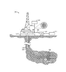
operations are still
expensive, increasingly environmentally challenging and emissions intensive.
Multi-stage
fracing operations already represent up to 70% of the total cost for each
well. If current trends
of increasing horizontal lateral length and adding more stages per well
continue using current
brute force approach, it is estimated that up to 25% of new wells will be
uneconomical.
[0007] Fracing or other forms of production stimulation methods such as
Improved Oil
Recovery (IOR) and Enhanced Oil Recovery (EOR) are typically used in either
conventional
or unconventional wellbores. The difference between what is commonly
understood as
conventional or unconventional relates to rock permeability, or rather, how
tight the
rock/formation is. Unconventional wells also tend to have vast and
unpredictable formation
variation (reservoir quality), and receive less attention, as profitability is
often reduced or
limited as a result of higher costs associated with well construction,
fracing, and fast
production decline.
[0008] In the event of dealing with an unconventional (or even conventional)
well,
production diagnostic tools may be used in order to predict well performance,
improve well
design, or aid in future well development. Typically, diagnostic or
surveillance tools include
fiber, PLT (production logging), fiber-optic, and liquid chemical tracers.
[0009] Use of fiber optic systems that include distributed acoustic sensing
(DAS) and
distributed temperature surveys (DTS) is known to provide high-end diagnostic
results.
However, fiber is known to be excessive in cost and deployment complexities,
and the time
to obtain useful data may be in the realm of weeks or longer. Depending on the
complexity,
the installation of fiber optic DAS and DTS systems can add as much as $1
million/well to
the completed total costs.
2
Date Recue/Date Received 2023-02-09
loom PLT also has its favored uses and is a historically well accepted
approach, but while
perhaps slightly lower in cost, it is known to provide a very short snapshot
view and
information compared to fiber and requires well shut-in and costly wireline
intervention.
[0011] Conventional chemical liquid tracers that are dissolvable in oil or
water have enjoyed
success but are also known to have limitations. These tracers are dissolvable
in oil and water
phases, and typically have fluorescent properties, DNA and ionic, organic
materials, or
radioactive diagnostic isotopes. Such tracers are used to evaluate fracturing
performance,
ostensibly to control the effectiveness of multi-stage hydraulic fracturing
stimulation. Owing
to obvious environmental deficiencies, tracers incorporating radioactive
isotopes have largely
fallen out of favor. Given their soluble characteristics, conventional
chemical tracers must be
tailored for individual fluid types, thereby requiring more, and often exotic,
formulations for
a single stage, increasing the chemical tracer costs appreciably.
[0012] Given the inherent heterogeneity of the rock along a typical horizontal
lateral (i.e.,
horizontal wellbore) and the assorted fluid streams, the different types of
liquid chemical
tracers required could add up significantly in incremental costs/well.
Furthermore, once
liquid-based tracers have been pumped, they disseminate quickly and flush from
the proppant
pack, shortening the effective monitoring period significantly. Thus, between
occasionally
inconclusive accuracy, cross-well contamination, and downhole temperature
restrictions
(limited to 400 F), the use of contemporary liquid tracers is limited.
[0013] In the same vein, conventional tracer testing is severely restricted by
the time required
to obtain a comprehensive interpretation of the test results. This is normally
accomplished
from an offsite lab with a minimum three-week turnaround on average, given the
longer
sample preparation time, very expensive instrumentation, sensitive samples
dissolution
process and specialized argon gas and reagents needed for analysis
[0014] Perhaps one of the more glaring drawbacks with liquid tracers is the
limitation to only
chemical measurement techniques at a molecular level, and the frequent
instigation of
unnecessary signals to what is erroneously perceived as "frac-hits". A frac
hit is typically
described as a fracture-driven inter-well communication event where an offset
well, often
termed a parent well in this setting, is affected by the pumping of a frac
treatment in a new
well, called the child well.
[0015] Each of the aforementioned techniques: fiber, PLT, and liquid chemical
tracer tools
have temperature limitations (i.e., for use in < 700 F) that make their use
problematic at best
in unconventional reservoirs as well as geothermal formations, where
temperatures may be as
high as 800 F.
3
Date Recue/Date Received 2023-02-09
[0016] The industry needs a low-cost, stage-by-stage flow profiling method
that can be used
for assessing unconventional reservoirs quality, the completion designs, and
to advance the
multi-stage fracing diagnostics to the next level.
[0017] Moreover, reducing emissions and environmental footprint from multi-
stage hydraulic
fracturing operations is a high-priority metric in oil and gas, as operators
staunchly embraced
environmental, social and governance (ESG) initiatives. In addition, fracture-
driven
interactions between fractures of the new wells (i.e., child wells) with
adjacent horizontal
wells (i.e., parent wells) and their costly negative effects have become the
focus of much
discussion and debate within the technical community. The negative impact of
these frac-to-
frac interactions on well productivity, including a rapid drop in production,
poor well
economics and the mechanical integrity of these parent wells, was the driving
force behind
such attention.
[0018] The need for a novel ultrahigh resolution nanoparticle tracer that is
versatile,
affordable, highly accurate, non-radioactive, non-intrusive and quick to test
is increasing as
never before for all subsurface, production and injection applications.
[0019] Thus, there is an urgent need to have accurate, affordable, timely data
on the
performance of individual stages, measured intra-well and frac-to-frac
communication. What
is needed is a new and improved way of forming and using a fast, cost-
favorable, effective,
and reliable way of predicting and validating wellbore performance.
SUMMARY
[0020] Embodiments of the disclosure pertain to a method of using a tracer
additive in a
wellbore that may include one or more steps described herein.
[0021] The method may include forming a utility fluid mixture comprising the
tracer
additive. Another step may be disposing the utility fluid into the wellbore.
This may occur
or be accomplished at a sufficient flow rate and pressure so that the utility
fluid comes into
contact with a target formation. The target formation may be in (fluid)
communication with
the wellbore.
[0022] Upon contacting the utility fluid with the target formation for an
amount of time, the
method may include returning a remnant fluid to a surface or surface facility.
The produced
remnant fluid may include a portion of the utility fluid (or some of its
initial constituents,
such as the first tracer).
[0023] The method may include taking a sample of the remnant fluid. In that
event, the
method may include testing the sample in order to analyze the remnant fluid.
At this point
4
Date Recue/Date Received 2023-02-09
this may result in obtaining or otherwise providing a set of fluid data
associated therewith.
The method may include integrating the set of fluid data with other wellbore
data in order to
determine a parameter associated with performance of the wellbore.
[0024] In aspects, the tracer additive may have a first tracer composition. In
other aspects,
the tracer additive may be in a solid powder form. The powder may have an
average particle
diameter of at least 0.1 gm to no more than 10 gm.
[0025] The tracer additive may have been an average bulk specific gravity of
at least 0.6
g/cm3 to no more than 1.2 g/cm3.
[0026] The wellbore or target formation may have various parameters associated
with it. For
example, the wellbore or target formation may be associated with a formation
temperature of
at least 1000 F to no more than 2000 F. In other aspects, the wellbore or
target formation
may have an average permeability of 0.1 nanodarcy to 1000 nanodarcy.
[0027] The target formation may be part of a geothermal well, EOR process, or
horizontal
drilled well associated with hydraulic fracturing. In aspects, the remnant
fluid may be used in
an energy generation process. For example, a fluid may be injected into the
geothermal well,
energy (such as heat) added thereto, and then the fluid is produced to the
surface, where the
added energy may be converted in the energy generation process.
[0028] In some embodiments, the method may include disposing a second tracer
additive into
the wellbore. This may be done in a manner so that the second tracer additive
comes into
contact with one or more of the target formation, another target formation
proximate to the
wellbore, or combinations thereof.
[0029] The second tracer additive may have a different composition from the
chemical
additive (or first tracer additive). The second tracer may be in powder form.
The second
tracer additive may have an average particle diameter of at least 0.1 gm to no
more than 10
gm. The second tracer additive may have an average bulk specific gravity of at
least 0.6
g/cm3 to no more than 1.2 g/cm3.
[0030] The target formation may be associated with a frac stage. The wellbore
or target
formation may be associated with a formation temperature of at least 450 F.
The formation
temperature may be no more than 2000 F.
[0031] In aspects, the testing the sample step comprises using a fluorescence
response-based
analysis. The fluorescence response-based analysis may include EDXRF. The
fluorescence
response-based analysis may include XRD.
[0032] These and other embodiments, features and advantages will be apparent
in the
following detailed description and drawings.
Date Recue/Date Received 2023-02-09
BRIEF DESCRIPTION OF THE DRAWINGS
[0033] A full understanding of embodiments disclosed herein is obtained from
the detailed
description of the disclosure presented herein below, and the accompanying
drawings, which
are given by way of illustration only and are not intended to be limitative of
the present
embodiments, and wherein:
[0034] Figure 1 shows a side view of a system for using a tracer additive in a
wellbore
according to embodiments of the disclosure;
[0035] Figure 2 is a side view of the system of Figure 1 where a remnant fluid
with the tracer
additive is produced from the wellbore according to embodiments of the
disclosure;
[0036] Figure 3 is a simplified block diagram of an analytical unit used to
test a sample
having a tracer additive according to embodiments of the disclosure;
[0037] Figure 4 is a side view of the system of Figure 1 for using a second
tracer additive in
a wellbore according to embodiments of the disclosure;
[0038] Figure 5 is a side view of a system for using a tracer additive in a
formation having
multiple wellbores according to embodiments of the disclosure;
[0039] Figure 6A shows a side view of a system for using a tracer additive in
a geothermal
well according to embodiments of the disclosure;
[0040] Figure 6B shows a side view of the system of Figure 6A where a remnant
fluid with
the tracer additive is produced from the wellbore according to embodiments of
the disclosure;
and
[0041] Figure 6C shows a side view of the system of Figure 6A where a remnant
fluid with
the tracer additive is produced from a proximate wellbore according to
embodiments of the
disclosure.
DETAILED DESCRIPTION
[0042] Regardless of whether presently claimed herein or in another
application related to or
from this application, herein disclosed are novel apparatuses, units, systems,
and methods that
pertain to use of solid tracer additives, details of which are described
herein.
[0043] Embodiments of the present disclosure are described in detail with
reference to the
accompanying Figures. In the following discussion and in the claims, the terms
"including"
and "comprising" are used in an open-ended fashion, such as to mean, for
example,
"including, but not limited to...". While the disclosure may be described with
reference to
relevant apparatuses, systems, and methods, it should be understood that the
disclosure is not
limited to the specific embodiments shown or described. Rather, one skilled in
the art will
6
Date Recue/Date Received 2023-02-09
appreciate that a variety of configurations may be implemented in accordance
with
embodiments herein.
[0044] Although not necessary, like elements in the various figures may be
denoted by like
reference numerals for consistency and ease of understanding. Numerous
specific details are
set forth in order to provide a more thorough understanding of the disclosure;
however, it will
be apparent to one of ordinary skill in the art that the embodiments disclosed
herein may be
practiced without these specific details. In other instances, well-known
features have not been
described in detail to avoid unnecessarily complicating the description.
Directional terms,
such as "above," "below," "upper," "lower," "front," "back," etc., are used
for convenience
and to refer to general direction and/or orientation, and are only intended
for illustrative
purposes only, and not to limit the disclosure.
[0045] Connection(s), couplings, or other forms of contact between parts,
components, and
so forth may include conventional items, such as lubricant, additional sealing
materials, such
as a gasket between flanges, PTFE between threads, and the like. The make and
manufacture
of any particular component, subcomponent, etc., may be as would be apparent
to one of skill
in the art, such as molding, forming, press extrusion, machining, or additive
manufacturing.
Embodiments of the disclosure provide for one or more components to be new,
used, and/or
retrofitted to existing machines and systems.
[0046] Various equipment may be in fluid communication directly or indirectly
with other
equipment. Fluid communication may occur via one or more transfer lines and
respective
connectors, couplings, valving, piping, and so forth. Fluid movers, such as
pumps, may be
utilized as would be apparent to one of skill in the art.
[0047] Numerical ranges in this disclosure may be approximate, and thus may
include values
outside of the range unless otherwise indicated. Numerical ranges include all
values from and
including the expressed lower and the upper values, in increments of smaller
units. As an
example, if a compositional, physical or other property, such as, for example,
molecular
weight, viscosity, melt index, etc., is from 100 to 1,000. it is intended that
all individual
values, such as 100, 101, 102, etc., and sub ranges, such as 100 to 144, 155
to 170, 197 to
200, etc., are expressly enumerated. It is intended that decimals or fractions
thereof be
included. For ranges containing values which are less than one or containing
fractional
numbers greater than one (e.g., 1.1, 1.5, etc.), smaller units may be
considered to be 0.0001,
0.001, 0.01, 0.1, etc. as appropriate. These are only examples of what is
specifically intended,
and all possible combinations of numerical values between the lowest value and
the highest
value enumerated, are to be considered to be expressly stated in this
disclosure. Numerical
7
Date Recue/Date Received 2023-02-09
ranges are provided within this disclosure for, among other things, the
relative amount of
reactants, surfactants, catalysts, etc. by itself or in a mixture or mass, and
various temperature
and other process parameters.
Terms
[0048] The term "connected" as used herein may refer to a connection between a
respective
component (or subcomponent) and another component (or another subcomponent),
which can
be fixed, movable, direct, indirect, and analogous to engaged, coupled,
disposed, etc., and can
be by screw, nut/bolt, weld, and so forth. Any use of any form of the terms
"connect",
"engage", "couple", "attach", "mount", etc. or any other term describing an
interaction
between elements is not meant to limit the interaction to direct interaction
between the
elements and may also include indirect interaction between the elements
described.
[0049] The term "fluid" as used herein may refer to a liquid, gas, slurry,
single phase, multi-
phase, pure, impure, etc. and is not limited to any particular type of fluid
such as
hydrocarbons.
[0050] The term "utility fluid" as used herein may refer to a fluid used in
connection with
any fluid disposed into a wellbore (akin to an injection fluid). The utility
fluid may be
pressurized, and may be used to carry an additive into the wellbore. 'Utility
fluid' may also
be referred to and interchangeable with 'service fluid' or comparable.
[0051] The term "fluid connection", "fluid communication," "fluidly
communicable," and
the like, as used herein may refer to two or more components, systems, etc.
being coupled
whereby fluid from one may flow or otherwise be transferrable to the other.
The coupling
may be direct, indirect, selective, alternative, and so forth. For example,
valves, flow meters,
pumps, mixing tanks, holding tanks, tubulars, separation systems, and the like
may be
disposed between two or more components that are in fluid communication.
[0052] The term "pipe", "conduit", "line", "tubular", or the like as used
herein may refer to
any fluid transmission means, and may be tubular in nature.
[0053] The term "tubestring" or the like (such as `workstring') as used herein
may refer to a
tubular (or other shape) that may be run into a wellbore. The tubestring may
be casing, a
liner, production tubing, combinations, and so forth. The tubestring may be
multiple pipes
(and the like) coupled together. The tubestring may be used for transfer of
fluids, or used with
some other kind of action, such as drilling, running a tool, or any other kind
of downhole
action, and combinations thereof.
8
Date Recue/Date Received 2023-02-09
[0054] The term "composition" or "composition of matter" as used herein may
refer to one or
more ingredients, components, constituents, etc. that make up a material (or
material of
construction). Composition may refer to a flow stream of one or more chemical
components.
[0055] The term "chemical" as used herein may analogously mean or be
interchangeable to
material, chemical material, ingredient, component, chemical component,
element, substance,
compound, chemical compound, molecule(s), constituent, and so forth and vice
versa. Any
'chemical' discussed in the present disclosure need not refer to a 100% pure
chemical. For
example, although 'water' may be thought of as H20, one of skill would
appreciate various
ions, salts, minerals, impurities, and other substances (including at the ppb
level) may be present
in 'water'. A chemical may include all isomeric forms and vice versa (for
example, "hexane",
includes all isomers of hexane individually or collectively).
[0056] The term "water" as used herein may refer to a pure, substantially
pure, and impure
water-based stream, and may include wastewater, process water, fresh water,
seawater, produced
water, slop water, treated variations thereof, mixes thereof, etc., and may
further include
impurities, dissolved solids, ions, salts, minerals, and so forth. Water for a
frac fluid can also be
referred to as 'frac water'.
[0057] The term "impurity" as used herein may refer to an undesired component,
contaminant, etc. of a composition. For example, a mineral or an organic
compound may be
an impurity of a water stream.
[0058] The term "frac fluid" as used herein may refer to a fluid injected into
a well as part of a
frac operation. Frac fluid is often characterized as being largely water, but
with other
constituents such as proppant, friction reducers, and other additives or
compounds.
[0059] The term "produced fluid", "production fluid", and the like as used
herein may refer to
water, gas, mixtures, and the like recovered from a subterranean formation or
other area near the
wellbore. Produced fluid may include hydrocarbons or aqueous, such as flowback
water, brine,
salt water, or formation water. Produced water may include water having
dissolved and/or
free organic materials. Produced fluid may be akin to `wellbore fluid', in
that the fluid may
be returned from the wellbore. Produced fluid may include utility fluids and
formation fluids.
[0060] The term "frac operation" as used herein may refer to fractionation of
a downhole
well that has already been drilled. 'Frac operation' can also be referred to
and
interchangeable with the terms fractionation, hydraulic fracturing, well
stimulation,
production enhancement, hydrofracturing, hydrofracking, fracking, fracing, and
frac. A frac
operation can be land or water based. Generally, the term `fracing' or 'frac'
is used herein,
but meant to be inclusive to other related terms of industry art.
9
Date Recue/Date Received 2023-02-09
[0061] The phrase "processing a fluid" as used herein may refer to some kind
of active step
or action, such as man-made or by machine, imparted on the fluid (or fluids).
For example, a
fluid may be received into a device (such as a mixer) and upon processing, may
leave as a
'processed fluid'. 'Processed' is not meant be limited, as this may include
reference to
transferred, treated, tested, measured, mixed, sensed, separated,
combinations, etc. in whatever
manner may be desired or applicable for embodiments herein. It is noted that
while various
steps or operations of any embodiment herein may be described in a sequential
manner, such
steps or operations may be operated in batch or continuous fashion.
[0062] The term "conventional well" as used herein may refer to a subterranean
formation
having an average permeability in the magnitude range of a millidarcy or
higher.
[0063] The term "unconventional well" as used herein may refer to a
subterranean formation
having an average permeability in the magnitude range of a nanodarcy or
smaller.
[0064] The term "tracer" as used herein may refer to an identifiable
substance, such as a
liquid dye, liquid chemical or a particles powder, which may be followed
through the course
of a mechanical, chemical, or biological process. In the present disclosure, a
tracer may be
used in a well, and the resultant process impact on the tracer evaluated. In
this respect, the
tracer may help evaluate, determine, and otherwise model well production and
performance.
The tracer may be added (and thus may be referred to as a 'tracer additive' or
'additive') to a
utility (or service, injection, etc.) fluid disposed into the well.
[0065] The term "nanoparticle" as used herein may refer to a small particle
that ranges
between 1 to 1000 nanometers in size diameter, and is undetectable by the
human eye. A
tracer in powder form may be nanoparticles. A tracer additive of the present
disclosure may
be in powder form with an average bulk diameter in a range of about 0.1 gm to
about 10 gm.
[0066] The term "EDXRF" (Non-destructive Energy Dispersive X-Ray Fluorescence)
as
used herein may refer to a type of spectroscopy process (and may thus include
use of a
spectrometer) where a sample of material (such as a portion of produced fluid)
is 'excited' in
order to collect emitted fluorescence radiation, which may then be evaluated
for different
energies of the characteristic radiation from each of the different
constituents (or elements) in
the sample. The EDXRF process may be referred to as a fluorescence response-
based
analytical process.
[0067] EDXRF may be considered a non-destructive analytical technique used to
determine
the elemental composition of materials. EDXRF analyzers determine the
elemental
composition of a sample by measuring the fluorescent (or secondary detectable
energy) X-ray
emitted from a sample when it is excited by a primary X-ray source. EDXRF is
designed to
Date Recue/Date Received 2023-02-09
analyze groups of elements simultaneously to determine those elements presence
in the
sample and their relative concentrations - in other words, the elemental
composition of the
sample. Each of the elements present in a sample produces a unique set of
characteristic X-
rays that is a "fingerprint" for that specific element. X-rays have a very
short wavelength,
which corresponds to very high energy. All atoms have several electron
orbitals (K shell, L
shell, M shell, for example). When X-ray energy causes electrons to transfer
in and out of
these shell levels, X-ray fluorescence peaks with varying intensities are
created and will be
present in the spectrum. The peak energy identifies the element, and the peak
height or
intensity is indicative of its concentration.
[0068] The term "XRD" may refer to X-ray diffraction, which is a technique for
analyzing
the atomic or molecular structure of materials. It is non-destructive, and
works most
effectively with materials that are wholly, or part, crystalline. The
technique is often known
as x-ray powder diffraction because the material being analyzed typically is a
finely ground
down to a uniform state. Diffraction is when light bends slightly as it passes
around the edge
of an object or encounters an obstacle or aperture. The degree to which it
occurs depends on
the relative size of a wavelength compared to the dimensions of the obstacle
or aperture it
encounters.
[0069] All diffraction methods start with the emission of x-rays from a
cathode tube or
rotating target, which is then focused at a sample. By collecting the
diffracted x-rays, the
sample's structure can be analyzed. This is possible because each mineral has
a unique set of
d-spacings. D-spacings are the distances between planes of atoms, which cause
diffraction
peaks.
[0070] Referring now to Figure 1, Figure 2, Figure 3, Figure 4, and Figure 5
together, a side
view of a system (and related method) for using a tracer additive in a
wellbore; a side view of
the system of Figure 1 where a remnant fluid with the tracer additive is
produced from the
wellbore; a simplified block diagram of an analytical testing unit used to
test a sample having
a tracer additive; a side view of the system of Figure 1 for using a second
tracer additive in a
wellbore; and a side view of a system for using a tracer additive in a
formation having
multiple wellbores, respectively, according to embodiments disclosed herein,
are shown.
[0071] System 100 may include one or more components (or subcomponents)
coupled with
new, existing, or retrofitted equipment. System 100 may include one or more
units that are
skid mounted or may be a collection of skid units, and the system 100 may be
suitable for
onshore and offshore environments.
11
Date Recue/Date Received 2023-02-09
[0072] The system 100 may have various valves, flanges, pipes, pumps,
utilities, monitors,
sensors, controllers, flow meters, safety devices, etc., for accommodating
sufficient universal
coupling between system components and any applicable feedline/feed source of
a material to
be processed, any resultant product material to be discharged or transferred
therefrom, and
anything in between.
[0073] Figure 1 is meant to show in a simplistic manner embodiments herein,
and may not be
to scale. The system 100 may include a subterranean or earthen formation 101
having a
wellbore 103 drilled or otherwise formed therein. The formation 101 may be a
type of
conventional or unconventional reservoir. The formation 101 may contain
hydrocarbonaceous fluids, such as oil, natural gas, and/or other materials,
generally
designated as F. The formation 101 may include porous and permeable rock
containing liquid
and/or gaseous hydrocarbons. The formation may include a conventional
reservoir, an
unconventional reservoir, a tight gas reservoir, and/or other types of
reservoirs. Moreover, the
illustration of a mover (pump) 107 is not meant to infer other equipment is
not present, of
which one of ordinary skill in the art is well versed.
[0074] The system 100 may include one or more additional wellbores, production
wells, etc.
The example wellbore 103 shown in Figure 1 illustrates the wellbore 103 may
have at least a
partial horizontal trajectory. However, any wellbore of the system 100 may
include any
combination of horizontal, vertical, slant, curved, directional-drilled,
and/or other well
geometries.
[0075] The wellbore 103 may be open, closed, cased, uncased, etc. Although not
shown in
detail here, the wellbore 103 may have a tubestring 119 disposed therein, such
as for
deploying tools or fluids into the wellbore 103. In other aspects, the
tubestring 119 may be a
production tubing, whereby formation and wellbore fluids may be readily
transported to a
surface or surface facility 102.
[0076] The formation 101 may include a target formation 101a, which may be
believed to be
a hydrocarbon-rich area of the formation 101. The target formation 101a may be
a stage or
zone, which may be part of or associated with a fracing operation. Just the
same, the target
formation 101a may just be part of the formation 101 without the need for
enhanced oil
recovery (EOR) or other type of treatment.
[0077] In the event of EOR, and although not limited to any particular type of
EOR/IOR or
comparable operation, in multistage fracturing, the wellbore 103 may require
the stimulation
and production of one or more zones of a formation. Conventionally, a liner,
casing, or other
type of tubestring 119 may be used downhole, in which the tubestring 119
includes one or
12
Date Recue/Date Received 2023-02-09
more downhole frac valves (any may further include, but not be limited to,
ported sleeves or
collars) at spaced intervals along the wellbore. Just the same, the target
formation 101a may
be fractured with a plug-and-perf operation.
[0078] It may be the case that the target formation 101a has perforations 106.
The
perforations may result from a fracing operation or may naturally exist. The
perforations 106
shown here are exaggerated in scale for ease of understanding to the reader,
but may in
reality be small in scale.
[0079] In the event of tight formation characteristics, such as in the case of
an
unconventional reservoir, the target formation 101a may have an average
permeability of
about 0.1 nanodarcy to about 1000 nanodarcy. By way of comparison, the target
formation
101a may be disposed in a conventional reservoir, and thus may have an average
permeability in a range of about 0.1 millidarcy to about 1 darcy (or more).
[0080] The formation 101 might have other geologic characteristics, including
hot formation
temperatures. For example, the target formation 101a may have an average
formation
temperature T of about 450 F. In embodiments, the average formation
temperature T may be
in a range of about 100 F to about 800 F. The formation temperature T may
have a
relationship to the depth, geological environment, and tightness of the
formation 101.
[0081] Diagnostic information about the performance of the wellbore 103 may be
determined
by utilizing a first tracer additive 105a. The first tracer additive 105a (or
other tracer additives
described herein) may be of a suitable material for use with any type of
formation 101. Just
the same, the first tracer additive 105a may have a (predetermined) first
composition A,
which results in characteristics (or traits) suitable for use in the event the
formation 101 has
conditions normally undesirable for the use of tracers, namely, liquid
tracers.
[0082] As a first characteristic, the first tracer 105a may be a solid tracer
in the form of a
powder. The use of powder form makes the first tracer 105a attractive for use
in high
temperature conditions. The first tracer 105a may comprise powder
nanoparticles. In
embodiments, the particles of the first tracer 105a may have an average
particle diameter of
about 0.1 gm to about 10 gm. The first tracer 105a may have a first tracer
specific gravity. In
embodiments, the first tracer 105a may have an average bulk specific gravity
of about 0.6
g/cm3 to about 1.2 g/cm3.
[0083] The first tracer 105a may be transferred (e.g., a blower, pump, gravity
feed, etc.) from
a tracer feed source 110 (such as a hopper or the like), and mixed with a
carrier fluid 104.
The carrier fluid 104 may be or include water. Other materials may be mixed
with the carrier
fluid, such as sand, proppant, etc. The carrier fluid 104 may be transferred
toward mixer or
13
Date Recue/Date Received 2023-02-09
mixing point 108 from a carrier fluid source 111. For example, a pump 107 may
be used to
pump the carrier fluid 104 from the source 111 toward a wellhead (injection
point) 117, and
through the tubestring 119.
[0084] The mixer 108 may be any device suitable to form an injection or
utility fluid mixture
104a. The first tracer 105a may be completely miscible with the carrier fluid
104. The first
tracer 105a may be inert in the respect that there is no effect by the first
tracer 105a on the
carrier fluid 104 and/or the formation 101 (or target formation 101a) and/or
vice versa.
[0085] Suitable equipment such as the pump 107 may be used for the transfer
and disposing
of the utility mixture 104a into the wellbore 103. Sufficient pressure and
flowrate may be
selected and used in order to adequately provide the utility mixture 104a to
the target
formation 101a. The first tracer 105a may exit the tubestring 119, and
eventually come into
contact with the target formation 101a and/or the perforations 106. The tracer
105a may be
provided to the target formation 101a through standard flow configurations,
such as
ports/sleeves within the tubestring 119, or out of a toe, and vice versa for
production to the
surface 102.
[0086] The tracer 105a (or at least a portion thereof) may have an average
residence time in
the target formation 101a and/or the perforations 106. In the event the system
100 uses a
fracing operation for a stage or a zone, the first tracer additive 105a may be
selected for its
particular uniqueness, and thus preferably has a different tracer
characteristic (fingerprint)
from other tracer additives used in the fracing operation so that fluid
returned from each
particular stage may be identified. The tracer characteristic may be the
chemical identity of
the tracer additive used, such as composition or specific gravity. The tracer
characteristic may
be distinguishable from the tracer characteristic(s) of any other tracer
additives used.
[0087] Figures 2 and 3 illustrate whereby the first tracer 105a may be brought
back to the
surface 102 for testing. For example, after the predetermined time period, a
remnant fluid
104b may be produced. The remnant fluid 104b may include, at least partially,
(some of) the
first tracer 105a, the carrier fluid, and formation fluids F. A sample of the
remnant fluid 104b
may be produced on a desired frequency, such as daily. The sampling can occur
during the
desired frequency over a predetermined timeframe, which may be days or months
(e.g., 6
months).
[0088] Once the remnant fluid 104b is produced from the wellbore 103, a sample
113 may be
taken or extracted from sample point 112. The rest of the remnant fluid 104b
may be
transferred to a desired destination 114, which may be a tank, a pond, another
well, or other
suitable storage.
14
Date Recue/Date Received 2023-02-09
10089] The sample 113 may now be tested via test unit 120. The test unit 120
may include
analysis equipment 115, which may be in operable communication with computing
system
118. The computing system 118 may be configured for use in using analytical
data associated
with use of the test equipment 115. The test equipment 115 may provide a
fluorescence
response-based process, such as EDXRF and XRD.
[0090] The computing system 118 may be useful to further analyze data and
other
information in order to provide an indication related to performance of the
wellbore 103. This
may pertain to, for example, the time the tracer additive was detected, the
location where the
tracer additive was use, the type and composition of the tracer additive
detected, the amount
or concentration of tracer additive detected, and/or other measurements
provided by the
equipment 115 and the system 118.
[0091] The computing system 118 may have Artificial intelligence (A.I.) based
diagnostics.
The computing system 118 may access input data 121, which may be related to
other aspects
of the formation 101, such as geological information, fractures, and the like.
The computing
system 118 may include programs, scripts, and/or other types of computer
instructions that
generate output data 122, which may be based on the input data 121. The output
data 122
may include descriptions of fluid flow patterns in the formation 101, which
may identify
paths of fluid flow in the wellbore 101, wellbore breaches or cross-
communication (such as
to a proximate offset well), fracture locations, fluid flow rates, and/or
other information.
[0092] Figure 4 illustrates an analogous manner of disposing a second tracer
additive 105b
into the wellbore 103. The second tracer additive 105b may be like that of the
first tracer
additive 105b, and thus have similar composition and characteristics; however,
the second
tracer additive may have a second composition B different from that of the
first composition
A. The use of a different composition B provides a unique identifier and
fingerprint as
compared to that of the composition A.
[0093] The second composition B may be different from the first composition A,
yet the
second tracer 105b may have characteristics similar to that of the first
tracer 105a. For
example, the second tracer 105b may be an inert solid (in powder form) having
a respective
average particle diameter of about 0.1 gm to about 10 gm. The second tracer
105b may have
a respective average bulk specific gravity of about 0.6 g/cm3 to about 1.2
g/cm3.
[0094] The second tracer 105b may be transferred from the tracer feed source
110, and mixed
with the carrier fluid 104 at mixer or mixing point 108 to form the utility
mixture 104a. The
utility mixture in this instance may thus include the carrier fluid 104 and
the second tracer
105b. Sufficient pressure and flowrate may be selected and used in order to
adequately
Date Recue/Date Received 2023-02-09
provide the utility mixture 104a to a new or second target formation 101b. The
second target
formation 101b may be associated with a stage or zone of a frac operation.
Just the same the
second target formation 101b may just be part of the formation 101. The second
target
formation 101b may have its own respective perforations 106.
[0095] As before with the first tracer 105a, after the predetermined time
period, a remnant
fluid 104b may be produced. The remnant fluid 104b may include, at least
partially, (some
of) the first tracer 105a, the second tracer 105b, the carrier fluid, and
formation fluids F.
[0096] Once the remnant fluid 104b is produced from the wellbore 103, a sample
113 may be
taken or extracted from sample point 112.
[0097] The system 100 may be modified or adjusted based on the detection of
tracers
released from the formation 101. For example, well system tools, and/or other
subsystems
may be installed, adjusted, activated, terminated, or otherwise modified based
on the
information provided by the tracers. Additional fractures can be formed in the
formation 101,
and/or other modifications can be made based on information provided by the
tracers. In
some embodiments, modifications of the system 100 may be selected and/or
parameterized to
improve production from the formation 101. For example, the modifications may
improve the
sweep efficiency. Modifications of well system 100 may be selected and/or
parameterized by
the computing system based on data analysis performed by the computing system.
[0098] Briefly, Figure 5 illustrates an embodiment where a utility fluid 104a
may disposed
into a wellbore 103 in a suitable manner to provide a first tracer additive
105a to a first target
formation 101a, and subsequently a second tracer additive 105b to a second
target formation
101b. Other tracers may be added for other areas of the formation 101. The
tracer additives
105a, 105b may be like that as described herein.
[0099] As shown here, there may be a plurality of wellbores, such as first
offset wellbore
103a and second offset wellbore 103b. In some embodiments, it may be desirous
to establish
far-field analysis or otherwise detect cross-communication 116 or breakthrough
between the
wellbores 103, 103a, 103b. As shown here, the first tracer additive 105a may
pass from the
wellbore 103 into any of the offset wellbores via flowpath 116. Similarlily,
the second tracer
additive 105b may pass from the wellbore 103 to any of the offset wellbores
via flowpath
116. Other tracer additives may be used and passed, as well.
loom] Remnant fluids 104b1, 104b2 may be produced from the respective
wellbores and
have samples taken and tested in accordance with embodiments herein.
16
Date Recue/Date Received 2023-02-09
pow Briefly, Figure 6C illustrates a side view of a system for using a tracer
additive in a
geothermal well, and a side view where a remnant fluid with the tracer
additive is produced
from another nearby well. For example, cross-communication 116 may exist
between the
wellbore 103 and the nearby wellbore 103a. As such, the remnant fluid 104b may
be
produced from the nearby wellbore 103a.
Example
[00102] Embodiments herein provide for a method of subsurface flow mapping
using ultrahigh
resolution nanoparticle tracer technology. Methods of the disclosure may
provide for a tracer
portfolio that integrates advanced computational methods using Artificial
Intelligence (A.I.).
Such use may provide accurate, actionable, near real-time performance-flow-
profile data.
This may allow oil and gas operators to: optimize completion strategies;
achieve the best
production per foot; reduce completion and fracturing cost; and/or reduce
environmental
footprint.
[00103] Tracer technology described herein may be based on proprietary inert
submicron
particles and other environmentally friendly and cost-effective additives that
are used to
manufacture the right composition of each tracer. This tracer technology may
utilize special
inert particles fingerprinting with certain atoms as special indicators that
enhance the
properties of each tracer. These may then detected at the sub-atomic structure
level using
robust capabilities of EDXRF-type spectroscopy measurements, and therefore
ensuring
superior accuracy for each tracer's detection and characterization from
different subsurface
environments.
[00104] The tracer additives may be injected at the parts per million (PPM)
concentrations via
mixer or blender equipment, and pumped (injected) downhole into well using
high-pressure
pumps for any given fracturing stage. The mixer equipment may be designed to
integrate a
slurry of water, sand, dry chemicals, and liquid chemicals to provide the
desired fracing
components and fluid rheology for any target formation.
[00105] After a completion process is completed and the well flown back, the
deployed tracers
are then recovered with production flowback or produced fluids from treatment
or/and
adjacent wells.
[00106] During the back flowing of the well, reservoir oil/gas samples are
taken on a regular
basis, such as for the first 10 to 40 days. The number of days may as desired,
such as up to
180 days. A small amount of the sample is analyzed using appropriate methods
to detect the
presence and concentration of tracer compound. Samples from traced and/or
offset wells may
17
Date Recue/Date Received 2023-02-09
be collected on a predetermined basis (such as daily) from production flowback
at the
wellhead or other suitable sample point. The sample may then be tested via a
fluorescence
response-based process, such as EDXRF and XRD. Such analytical techniques may
be used
to determine the elemental composition and crystallinity of the samples.
[00107] EDXRF is designed to analyze groups of elements simultaneously to
determine those
elements presence in the sample and their relative concentrations - in other
words, the
elemental composition of the sample. Each of the elements present in a sample
produces a
unique set of characteristic X-rays that is a "fingerprint" for that specific
element. X-rays
have a very short wavelength, which corresponds to very high energy.
[00108] Due to sub-atomic accuracy of both detection methods, it is possible
to precisely
determine the elemental composition, crystallographic structure, and the
various
combinations of hyperfine interactions in the samples, which enables very
accurate
identification of the tracer additives on the sub-atomic or quantum level.
[00109] Laboratory analysis that may include or incorporate advanced
computational methods
and proprietary diagnostics capabilities for each stage or target formation
provides accurate,
calibrated, actionable and cost-effective production diagnostics results. This
enables
operators to reduce operational cost and increase the production in oil and
gas wells.
loom] Embodiments herein may produce and achieve an extensive and long-term
dataset
from tracer additives during production flow profile analysis at each target
formation. This
information may be used together with advanced computational methods using
Artificial
Intelligence (A.I.) coupled with artificial neural network may provide precise
completion
optimization workflows for oil and gas wells.
[00111] Embodiments herein pertain to a method(s) of using a tracer additive
in a wellbore. The
method may include one or more steps, which may vary in sequence and scope.
The method
may include forming a utility fluid mixture comprising the tracer additive.
Forming may
occur from inline mixing of the like. The utility fluid may then be disposed
or otherwise
transferred into the wellbore.
[00112] The utility fluid may be disposed at a sufficient flow rate and
pressure so that the
utility fluid comes into contact with a target formation in communication with
the wellbore.
A such, the flow rate and pressure may be adequate to transfer the utility
fluid through a
tubestring, into the wellbore, and then into contact with the target formation
(such as through
sleeve ports, a toe sleeve, or the like).
[00113] Upon contacting the utility fluid with the target formation for an
amount of time
(which may be predetermined or as otherwise desired), the method may include
returning
18
Date Recue/Date Received 2023-02-09
(producing, etc.) a remnant fluid to a surface. One of skill would appreciate
the surface refers
to above-ground production equipment, facilities, and so forth, being common
in fracing
operations.
[00114] The method may include taking a sample of the remnant fluid, and then
testing the
sample in order to analyze the remnant fluid in order to provide a set of
fluid data. The
method may include integrating (or otherwise analyzing, comparing, etc.) the
set of fluid data
with other wellbore data in order to determine a parameter associated with
performance of the
wellbore.
[00115] The method may utilize the tracer additive having a first tracer
composition. The
tracer additive may be in powder (i.e., solid) form having an average particle
diameter of at
least 0.1 gm to no more than 10 gm. The tracer additive may have an average
bulk specific
gravity. For example, the average bulk specific gravity may be in a range of
at least 0.6
g/cm3 to no more than 1.2 g/cm3.
[00116] The wellbore may be associated with extreme conditions, such as
formation
temperature of at least 1000 F to no more than 2000 F. The formation (or the
target
formation) may have an average permeability of 0.1 nanodarcy to 1000
nanodarcy. In
aspects, the target formation may be part of a geothermal well. In this
respect, the remnant
fluid may be used in an energy generation process.
[00117] The method may include additional steps, such as disposing a second
tracer additive
into the wellbore. The disposing step may be done in such a manner that the
second tracer
additive may come into contact with one or more of the target formation,
another target
formation proximate to the wellbore, or combinations thereof.
[00118] The second tracer additive may have a different composition from the
first chemical
tracer, but otherwise may also be in powder form, may have an average particle
diameter of
at least 0.1 gm to no more than 10 gm, and may have average bulk specific
gravity of at least
0.6 g/cm3 to no more than 1.2 g/cm3.
[00119] The target formation may be associated with a frac stage, wherein the
wellbore is
associated with a formation temperature of at least 450 F to no more than
2000 F, and
wherein the target formation has an average permeability of 0.1 nanodarcy to
1000
nanodarcy. The testing the sample step may include using a fluorescence
response-based
analysis. In aspects, the fluorescence response-based analysis comprises
EDXRF. In aspects,
the fluorescence response-based analysis comprises XDR.
19
Date Recue/Date Received 2023-02-09
Advanta2es
[00120] Embodiments herein may provide for a new and improved method and
system related to
the use of chemical tracers in various settings associated with an earthen
formation, such as an
oil and gas well or a geothermal well.
[00121] The tracer may be cost-effective and inert, stable at (excessively)
high temperatures,
compatible with formation fluids, non-intrusive to completion design, easy to
use, and quickly
tested. Other advantages may include use of tracers that are of a cost-
effective material, inert
and lightweight, easily deployed, non-hazardous and non-radioactive, a single
tracer for water
and oil phases, and precise sub-atomic accuracy.
[00122] While preferred embodiments of the disclosure have been shown and
described,
modifications thereof may be made by one skilled in the art without departing
from the spirit
and teachings of the disclosure. The embodiments described herein are
exemplary only and
are not intended to be limiting. Many variations and modifications of the
embodiments
disclosed herein are possible and are within the scope of the disclosure.
Where numerical
ranges or limitations are expressly stated, such express ranges or limitations
should be
understood to include iterative ranges or limitations of like magnitude
falling within the
expressly stated ranges or limitations. The use of the term "optionally" with
respect to any
element of a claim is intended to mean that the subject element is required,
or alternatively, is
not required. Both alternatives are intended to be within the scope of the
claim. Use of
broader terms such as comprises, includes, having, etc. should be understood
to provide
support for narrower terms such as consisting of, consisting essentially of,
comprised
substantially of, and the like.
[00123] Accordingly, the scope of protection is not limited by the description
set out above
but is only limited by the claims which follow, that scope including all
equivalents of the
subject matter of the claims. Each and every claim is incorporated into the
specification as an
embodiment of the present disclosure. Thus, the claims are a further
description and are an
addition to the preferred embodiments of the present disclosure. The inclusion
or discussion
of a reference is not an admission that it is prior art to the present
disclosure, especially any
reference that may have a publication date after the priority date of this
application. The
disclosures of all patents, patent applications, and publications cited herein
are hereby
incorporated by reference, to the extent they provide background knowledge; or
exemplary,
procedural or other details supplementary to those set forth herein.
Date Recue/Date Received 2023-02-09