Note: Descriptions are shown in the official language in which they were submitted.
CA 03189118 2023-01-06
WO 2022/031689 PCT/US2021/044321
ELECTRIC VEHICLE (EV) FAST RECHARGE STATION AND SYSTEM
FIELD
The present invention is directed to a fast or high speed electric vehicle
recharge
station and system, for example, for high speed recharging of electric
vehicles (EVs).
The fast or high speed electrical vehicle station and system can be configured
to
provide both high speed recharging of electric vehicles and filling of fuel
powered
vehicles.
BACKGROUND
Electric vehicles (EVs) have grown in use around the world with a strong
interest
in clean emissions, quiet driving, and low maintenance. Advancements in
battery
technology have supported improvements in vehicle speed as well as driving
distance.
Battery charging has improved to help support this growth and provide
recharging times
as low as two hours for a complete charge of large EV batteries (e.g. as in
Chevrolet
Volt or Tesla Model S). The push to improve recharge times has driven battery
manufacturers to improve technology and provide "fast charge" capability in
their
batteries. The goal is to allow EV cars to recharge in close to the same time
as refueling
a gasoline vehicle (e.g. 10-15 minutes).
A problem arises with fast recharging of large vehicle batteries because of
the
large amount of AC Power required from the utility power grid for each (or
multiple)
vehicle(s) during recharge. For example, a normal size sedan such as a
Chevrolet Volt
1
CA 03189118 2023-01-06
WO 2022/031689 PCT/US2021/044321
could require power as high as 350KW during the recharge process to achieve
targeted
recharge times. This power requirement when multiplied by several vehicles
being
charged simultaneously would require a huge AC Power source (such as utility
power
grid infrastructure to support a large industrial load, followed by AC/DC
conversion) at
the recharging site. This type of AC Power source is not available in most
locations. The
power surges during recharging also cause problems with the utility companies'
ability
to predict power requirements in specific locations. Adding to this particular
problem is
the sparse locations of recharge stations. EV recharge pumps must be available
at gas
stations to allow the EV market to grow.
SUMMARY
To provide sufficient power at most locations, power must be stored in a
controlled, even manner using a large "electric reservoir" or "battery
reservoir" or
"energy reservoir" or "power reservoir." This electric reservoir can then be
used as the
main recharge energy source for recharging the electric vehicles. Battery
technology
already exists to support the "reservoir" requirement. Several different
electric power
storage technologies can be used including flow batteries, lithium-ion
batteries, power
storage capacitors (e.g. ultra capacitors) and/or fuel cells. Other
electromechanical
technologies such as flywheel energy storage can also be used. The electric
reservoir
can be placed underground in a similar fashion currently used for storing fuel
(e.g.
gasoline, diesel) in a gas station or it can be placed above ground.
2
CA 03189118 2023-01-06
WO 2022/031689 PCT/US2021/044321
The electric reservoir can be charged (e.g. constantly charged in an even
manner) using power that already exists at a normal gas station. Using this
method
allows the utility company to predict the power usage and avoid power surges.
For
example, the electric reservoir can be recharged continuously, intermittently,
variable
current, variable charging rate, or in a programmed manner from an electrical
power
source (e.g. existing power source(s), new power source(s), electrical power
grid, power
transmission line(s), power distribution system, power station, electrical
generator, fuel
type electrical generator, solar panels, wind power generators).
The energy stored in the electric reservoir can be used as the power source
for
recharging the electric vehicle. A recharge pump, very similar (in physical
size and form)
to a regular gas pump can be used to make the proper conversion of power
required for
charging the EV. Since the power source for an EV is a DC battery and the
electric
reservoir can be a DC electric reservoir (e.g. DC flow battery, DC Li-ion
battery), the
power conversion required can simply be direct or a DC to DC conversion,
avoiding the
power losses with AC to DC conversions used in most battery chargers today.
The operator of the recharging station can charge customers for recharging
their
EVs in a manner similar to gasoline customers. They will be able to work with
the utility
company on the costs for keeping the reservoir charged as well as amortize the
costs
for adding/ supporting the reservoir and EV Chargers or EV Pumps (e.g.
electric
chargers or outlets). The operator can build in profits required and charge
the EV
customers accordingly. This removes the burden for utility companies of having
to
provide industrial sized power grid infrastructure, such as additional towers,
power lines,
substations, which might be impractical for most locations.
3
CA 03189118 2023-01-06
WO 2022/031689 PCT/US2021/044321
Using a reservoir approach allows a normal gas station to be converted by
simply
adding an EV Pump (e.g. refueling EV pump) or multiple pumps to provide fast
charging
of EV(s). This fast charging will allow EV(s) to easily travel across country
just like a
gasoline fueled vehicle does today, which will allow EV(s) to become more
mainstream.
The presently described subject matter is directed to a station for refueling
fuel
vehicles and/or recharging electric vehicles.
The presently described subject matter is directed to an electric recharge
station.
The presently described subject matter is directed to an electric/fuel
station.
The presently described subject matter is directed to an improved gas station
comprising or consisting of both gas pumps and electric pumps or EV chargers.
The presently described subject matter is directed to an electric
recharge/fuel
station comprising or consisting of at least one fuel pump and at least one
electric pump
or EV charger.
The presently described subject matter is directed to an electric
recharge/fuel
station comprising or consisting of at least one fuel pump and at least one
electric pump
or EV charger.
The presently described subject matter is directed to an electric
recharge/fuel
station comprising or consisting of at least one fuel pump and at least one
electric pump
or charger, wherein the at least one fuel pump is spaced apart a predetermined
distance from the at least one electric pump or charger.
The presently described subject matter is directed to an electric
recharge/fuel
station comprising or consisting of at least one fuel pump and at least one
electric pump
4
CA 03189118 2023-01-06
WO 2022/031689 PCT/US2021/044321
or charger, wherein the at least one fuel pump and at least one electric pump
or charger
are provided in a single unit.
The presently described subject matter is directed to a fuel/electric station
comprising or consisting of at least one fuel pump and at least one electric
pump or
charger, wherein the at least one fuel pump and at least one electric pump or
charger
are separate units.
The presently described subject matter is directed to a fuel/electiric station
comprising or consisting of multiple fuel pumps and multiple electric pumps or
EV
chargers.
The presently described subject matter is directed to a fuel/electric station
comprising or consisting of multiple fuel pumps locate and multiple electric
pumps or
chargers, wherein the fuel pumps are located in at least one row and the
electric pumps
or chargers are located in at least one another row.
The presently described subject matter is directed to a fuel/electric station
comprising or consisting of at least one electric reservoir.
The presently described subject matter is directed to a fuel/electric station
comprising or consisting of multiple electric reservoirs.
The presently described subject matter is directed to a fuel/electric station
comprising or consisting of at least one onsite electric reservoir.
The presently described subject matter is directed to a fuel/electric station
comprising or consisting of at least one electric reservoir located below
ground level.
The presently described subject matter is directed to a fuel/electric station
comprising or consisting of multiple electric reservoirs located below ground
level.
CA 03189118 2023-01-06
WO 2022/031689
PCT/US2021/044321
The presently described subject matter is directed to a fuel/electric station
comprising or consisting of at least one electric reservoir located above
ground level.
The presently described subject matter is directed to a fuel/electric station
comprising or consisting of multiple electric reservoirs located above ground
level.
The presently described subject matter is directed to a fuel/electric station
comprising or consisting of at least one electric reservoir.
The presently described subject matter is directed to a fuel/electric station
comprising or consisting of multiple electric reservoirs.
The presently described subject matter is directed to a fuel/electric station
comprising or consisting of at least one onsite electrical reservoir.
The presently described subject matter is directed to a fuel/electric station
comprising or consisting of multiple onsite electric reservoirs.
The presently described subject matter is directed to a fuel/electric station
comprising or consisting of at least one electrical reservoir located below
ground level.
The presently described subject matter is directed to a fuel/electric station
comprising or consisting of multiple electric reservoirs located below ground
level.
The presently described subject matter is directed to a fuel/electric station
comprising or consisting of at least one electric reservoir located above
ground level.
The presently described subject matter is directed to a fuel/electric station
comprising or consisting of multiple electric reservoirs located above ground
level.
6
CA 03189118 2023-01-06
WO 2022/031689 PCT/US2021/044321
The presently described subject matter is directed to a fuel/electric station
comprising or consisting of at least one fuel tank and at least one electrical
reservoir
located below ground level.
The presently described subject matter is directed to a fuel/electric station
comprising or consisting of multiple fuel tanks and multiple electric
reservoirs located
below ground level.
The presently described subject matter is directed to a fuel/electric station
comprising or consisting of at least one gas tank and at least one electric
reservoir
located below ground level, wherein the at least one gas tank and at least one
electric
reservoir are spaced apart at least a predetermined distance.
The presently described subject matter is directed to an electric vehicle (EV)
charging station for charging an electric vehicle (EV), the EV charging
station
comprising or consisting of: a power source; an electrical service receiving
power from
the power source; a primary electric reservoir receiving power from the
electrical
service; a secondary electric reservoir receiving power from the primary
electric
reservoir; and a first EV charger receiving power from the secondary electric
reservoir.
The presently described subject matter is directed to an electric vehicle (EV)
charging station for charging an electric vehicle (EV), the EV charging
station
comprising or consisting of: a power source; an electrical service receiving
power from
the power source; a primary electric reservoir receiving power from the
electrical
service; a secondary electric reservoir receiving power from the primary
electric
reservoir; a tertiary electric reservoir receiving power from the secondary
electric
reservoir; and a first EV charger receiving power from the tertiary electric
reservoir.
7
CA 03189118 2023-01-06
WO 2022/031689 PCT/US2021/044321
The presently described subject matter is directed to an electric vehicle (EV)
charging station for charging an electric vehicle (EV), the EV charging
station
comprising or consisting of at least one power source; a plurality of
electrical services
receiving power from the at least one power source; a plurality of primary
electric
reservoirs receiving power, respectively, from the plurality of electrical
services; a
plurality of secondary electric reservoirs receiving power, respectively, from
the first
primary electric reservoirs; and a plurality of EV chargers receiving power,
respectively,
from the plurality of secondary electric reservoirs.
The presently described subject matter is directed to an electric vehicle (EV)
charging station for charging an electric vehicle (EV), the EV charging
station
comprising or consisting of: a power source; an electrical service receiving
power from
the power source; a primary electric reservoir receiving power from the
electrical
service; a secondary electric reservoir receiving power from the primary
electric
reservoir; and a first EV charger receiving power from the secondary electric
reservoir,
further comprising a tertiary electric reservoir receiving power from the
secondary
electric reservoir.
The presently described subject matter is directed to an electric vehicle (EV)
charging station for charging an electric vehicle (EV), the EV charging
station
comprising or consisting of: a power source; an electrical service receiving
power from
the power source; a primary electric reservoir receiving power from the
electrical
service; a secondary electric reservoir receiving power from the primary
electric
reservoir; and a first EV charger receiving power from the secondary electric
reservoir,
wherein the electrical service is a plurality of electrical services, the
primary electric
8
CA 03189118 2023-01-06
WO 2022/031689 PCT/US2021/044321
reservoir is a plurality of primary electric reservoirs receiving power,
respectively, from
the plurality of electrical services, the secondary electric reservoir is a
plurality of
secondary electric reservoirs receiving power, respectively, from the
plurality of primary
electric reservoirs, and the EV charger is a plurality of EV chargers
receiving power,
respectively, from the plurality of secondary electric reservoirs.
The presently described subject matter is directed to an electric vehicle (EV)
charging station for charging an electric vehicle (EV), the EV charging
station
comprising or consisting of: a power source; an electrical service receiving
power from
the power source; a primary electric reservoir receiving power from the
electrical
service; a secondary electric reservoir receiving power from the primary
electric
reservoir; a tertiary electric reservoir receiving power from the secondary
electric
reservoir; and a first EV charger receiving power from the tertiary electric
reservoir,
wherein the electrical service is a plurality of electrical services, the
primary electric
reservoir is a plurality of primary electric reservoirs receiving power,
respectively, from
the plurality of electrical services, the secondary electric reservoir is a
plurality of
secondary electric reservoirs receiving power, respectively, from the
plurality of electric
primary electric reservoirs, the tertiary electric reservoir is a plurality of
tertiary electric
reservoirs receiving power, respectively, from the plurality of secondary
electric
reservoirs, and the EV charger is a plurality of EV chargers receiving power,
respectively, from the plurality of tertiary electric reservoirs.
The presently described subject matter is directed to an electric vehicle (EV)
charging station for charging an electric vehicle (EV), the EV charging
station
comprising or consisting of: a power source; an electrical service receiving
power from
9
CA 03189118 2023-01-06
WO 2022/031689 PCT/US2021/044321
the power source; a primary electric reservoir receiving power from the
electrical
service; a secondary electric reservoir receiving power from the primary
electric
reservoir; and a first EV charger receiving power from the secondary electric
reservoir,
further comprising an AC to DC power converter receiving AC power from the
electrical
service and converting the AC power to DC power.
The presently described subject matter is directed to an electric vehicle (EV)
charging station for charging an electric vehicle (EV), the EV charging
station
comprising or consisting of: a power source; an electrical service receiving
power from
the power source; a primary electric reservoir receiving power from the
electrical
service; a secondary electric reservoir receiving power from the primary
electric
reservoir; and a first EV charger receiving power from the secondary electric
reservoir,
further comprising an AC to DC power converter receiving AC power from the
electrical
service and converting the AC power to DC power, further comprising a first DC
to DC
power converter receiving DC power from the AC to DC converter and converting
the
DC power to DC power for supplying DC power to the primary electric reservoir.
The presently described subject matter is directed to an electric vehicle (EV)
charging station for charging an electric vehicle (EV), the EV charging
station
comprising or consisting of: a power source; an electrical service receiving
power from
the power source; a primary electric reservoir receiving power from the
electrical
service; a secondary electric reservoir receiving power from the primary
electric
reservoir; and a first EV charger receiving power from the secondary electric
reservoir,
further comprising an AC to DC power converter receiving AC power from the
electrical
service and converting the AC power to DC power, further comprising a first DC
to DC
CA 03189118 2023-01-06
WO 2022/031689 PCT/US2021/044321
power converter receiving DC power from the AC to DC converter and converting
the
DC power to DC power for supplying DC power to the primary electric reservoir,
further
comprising a second DC to DC power converter receiving DC power from the
primary
electric reservoir and converting the DC power to DC power for supplying DC
power to
the secondary electric reservoir.
The presently described subject matter is directed to an electric vehicle (EV)
charging station for charging an electric vehicle (EV), the EV charging
station
comprising or consisting of: a power source; an electrical service receiving
power from
the power source; a primary electric reservoir receiving power from the
electrical
service; a secondary electric reservoir receiving power from the primary
electric
reservoir; and a first EV charger receiving power from the secondary electric
reservoir,
further comprising an AC to DC power converter receiving AC power from the
electrical
service and converting the AC power to DC power, further comprising a first DC
to DC
power converter receiving DC power from the AC to DC converter and converting
the
DC power to DC power for supplying DC power to the primary electric reservoir,
further
comprising a second DC to DC power converter receiving DC power from the
primary
electric reservoir and converting the DC power to DC power for supplying DC
power to
the secondary electric reservoir, further comprising a third DC to DC power
converter
receiving DC power from the secondary electric reservoir and converting the DC
power
to DC power for supplying DC power to the EV charger.
The presently described subject matter is directed to an electric vehicle (EV)
charging station for charging an electric vehicle (EV), the EV charging
station
comprising or consisting of: a power source; an electrical service receiving
power from
11
CA 03189118 2023-01-06
WO 2022/031689 PCT/US2021/044321
the power source; a primary electric reservoir receiving power from the
electrical
service; a secondary electric reservoir receiving power from the primary
electric
reservoir; and a first EV charger receiving power from the secondary electric
reservoir,
further comprising an AC to DC power converter receiving AC power from the
electrical
service and converting the AC power to DC power, further comprising a first DC
to DC
power converter receiving DC power from the AC to DC converter and converting
the
DC power to DC power for supplying DC power to the primary electric reservoir,
further
comprising a second DC to DC power converter receiving DC power from the
primary
electric reservoir and converting the DC power to DC power for supplying DC
power to
the secondary electric reservoir, further comprising a third DC to DC power
converter
receiving DC power from the secondary electric reservoir and converting the DC
power
to DC power for supplying DC power to the EV charger, wherein the EV charger
comprises a fourth DC to DC power converter for converting DC power to DC
power for
supplying DC power to the EV.
The presently described subject matter is directed to an electric vehicle (EV)
charging station for charging an electric vehicle (EV), the EV charging
station
comprising or consisting of: a power source; an electrical service receiving
power from
the power source; a primary electric reservoir receiving power from the
electrical
service; a secondary electric reservoir receiving power from the primary
electric
reservoir; a tertiary electric reservoir receiving power from the secondary
electric
reservoir; and a first EV charger receiving power from the tertiary electric
reservoir,
further comprising an AC to DC power converter receiving AC power from the
electrical
service and converting the AC power to DC power.
12
CA 03189118 2023-01-06
WO 2022/031689 PCT/US2021/044321
The presently described subject matter is directed to an electric vehicle (EV)
charging station for charging an electric vehicle (EV), the EV charging
station
comprising or consisting of: a power source; an electrical service receiving
power from
the power source; a primary electric reservoir receiving power from the
electrical
service; a secondary electric reservoir receiving power from the primary
electric
reservoir; a tertiary electric reservoir receiving power from the secondary
electric
reservoir; and a first EV charger receiving power from the tertiary electric
reservoir,
further comprising an AC to DC power converter receiving AC power from the
electrical
service and converting the AC power to DC power, further comprising a first DC
to DC
power converter receiving DC power from the AC to DC converter and converting
the
DC power to DC power for supplying DC power to the primary electric reservoir.
The presently described subject matter is directed to an electric vehicle (EV)
charging station for charging an electric vehicle (EV), the EV charging
station
comprising or consisting of: a power source; an electrical service receiving
power from
the power source; a primary electric reservoir receiving power from the
electrical
service; a secondary electric reservoir receiving power from the primary
electric
reservoir; a tertiary electric reservoir receiving power from the secondary
electric
reservoir; and a first EV charger receiving power from the tertiary electric
reservoir,
further comprising an AC to DC power converter receiving AC power from the
electrical
service and converting the AC power to DC power, further comprising a first DC
to DC
power converter receiving DC power from the AC to DC converter and converting
the
DC power to DC power for supplying DC power to the primary electric reservoir,
further
comprising a second DC to DC power converter receiving DC power from the
primary
13
CA 03189118 2023-01-06
WO 2022/031689 PCT/US2021/044321
electric reservoir and converting the DC power to DC power for supplying DC
power to
the secondary electric reservoir.
The presently described subject matter is directed to an electric vehicle (EV)
charging station for charging an electric vehicle (EV), the EV charging
station
comprising or consisting of: a power source; an electrical service receiving
power from
the power source; a primary electric reservoir receiving power from the
electrical
service; a secondary electric reservoir receiving power from the primary
electric
reservoir; a tertiary electric reservoir receiving power from the secondary
electric
reservoir; and a first EV charger receiving power from the tertiary electric
reservoir,
further comprising an AC to DC power converter receiving AC power from the
electrical
service and converting the AC power to DC power, further comprising a first DC
to DC
power converter receiving DC power from the AC to DC converter and converting
the
DC power to DC power for supplying DC power to the primary electric reservoir,
further
comprising a second DC to DC power converter receiving DC power from the
primary
electric reservoir and converting the DC power to DC power for supplying DC
power to
the secondary electric reservoir, further comprising a third DC to DC power
converter
receiving DC power from the secondary electric reservoir and converting the DC
power
to DC power for supplying DC power to the tertiary electric reservoir.
The presently described subject matter is directed to an electric vehicle (EV)
charging station for charging an electric vehicle (EV), the EV charging
station
comprising or consisting of: a power source; an electrical service receiving
power from
the power source; a primary electric reservoir receiving power from the
electrical
service; a secondary electric reservoir receiving power from the primary
electric
14
CA 03189118 2023-01-06
WO 2022/031689 PCT/US2021/044321
reservoir; a tertiary electric reservoir receiving power from the secondary
electric
reservoir; and a first EV charger receiving power from the tertiary electric
reservoir,
further comprising an AC to DC power converter receiving AC power from the
electrical
service and converting the AC power to DC power, further comprising a first DC
to DC
power converter receiving DC power from the AC to DC converter and converting
the
DC power to DC power for supplying DC power to the primary electric reservoir,
further
comprising a second DC to DC power converter receiving DC power from the
primary
electric reservoir and converting the DC power to DC power for supplying DC
power to
the secondary electric reservoir, further comprising a third DC to DC power
converter
receiving DC power from the secondary electric reservoir and converting the DC
power
to DC power for supplying DC power to the tertiary electric reservoir, further
comprising
a third DC to DC power converter receiving DC power from the tertiary electric
reservoir
and converting the DC power to DC power for supplying DC power to the EV
charger.
The presently described subject matter is directed to an electric vehicle (EV)
charging station for charging an electric vehicle (EV), the EV charging
station
comprising or consisting of: a power source; an electrical service receiving
power from
the power source; a primary electric reservoir receiving power from the
electrical
service; a secondary electric reservoir receiving power from the primary
electric
reservoir; a tertiary electric reservoir receiving power from the secondary
electric
reservoir; and a first EV charger receiving power from the tertiary electric
reservoir,
further comprising an AC to DC power converter receiving AC power from the
electrical
service and converting the AC power to DC power, further comprising a first DC
to DC
power converter receiving DC power from the AC to DC converter and converting
the
CA 03189118 2023-01-06
WO 2022/031689 PCT/US2021/044321
DC power to DC power for supplying DC power to the primary electric reservoir,
further
comprising a second DC to DC power converter receiving DC power from the
primary
electric reservoir and converting the DC power to DC power for supplying DC
power to
the secondary electric reservoir, further comprising a third DC to DC power
converter
receiving DC power from the secondary electric reservoir and converting the DC
power
to DC power for supplying DC power to the tertiary electric reservoir, further
comprising
a third DC to DC power converter receiving DC power from the tertiary electric
reservoir
and converting the DC power to DC power for supplying DC power to the EV
charger,
wherein the EV charger comprises a fifth DC to DC power converter for
converting DC
power to DC power for supplying DC power to the EV.
The presently described subject matter is directed to an electric vehicle (EV)
charging station for charging an electric vehicle (EV), the EV charging
station
comprising or consisting of: a power source; an electrical service receiving
power from
the power source; a primary electric reservoir receiving power from the
electrical
service; a secondary electric reservoir receiving power from the primary
electric
reservoir; and a first EV charger receiving power from the secondary electric
reservoir.
The presently described subject matter is directed to an electric vehicle (EV)
charging station for charging an electric vehicle (EV), the EV charging
station
comprising or consisting of: a power source; an electrical service receiving
power from
the power source; a primary electric reservoir receiving power from the
electrical
service; a secondary electric reservoir receiving power from the primary
electric
reservoir; a tertiary electric reservoir receiving power from the secondary
electric
16
CA 03189118 2023-01-06
WO 2022/031689 PCT/US2021/044321
reservoir; and a first EV charger receiving power from the tertiary electric
reservoir,
wherein the primary electric reservoir comprises a flow battery.
The presently described subject matter is directed to an electric vehicle (EV)
charging station for charging an electric vehicle (EV), the EV charging
station
comprising or consisting of: a power source; an electrical service receiving
power from
the power source; a primary electric reservoir receiving power from the
electrical
service; a secondary electric reservoir receiving power from the primary
electric
reservoir; and a first EV charger receiving power from the secondary electric
reservoir.
The presently described subject matter is directed to an electric vehicle (EV)
charging station for charging an electric vehicle (EV), the EV charging
station
comprising or consisting of: a power source; an electrical service receiving
power from
the power source; a primary electric reservoir receiving power from the
electrical
service; a secondary electric reservoir receiving power from the primary
electric
reservoir; a tertiary electric reservoir receiving power from the secondary
electric
reservoir; and a first EV charger receiving power from the tertiary electric
reservoir,
wherein the primary electric reservoir comprises a Li-ion battery.
The presently described subject matter is directed to an electric vehicle
(EV) charging station for charging an electric vehicle (EV), the EV charging
station
comprising or consisting of: a power source; an electrical service receiving
power from
the power source; a primary electric reservoir receiving power from the
electrical
service; a secondary electric reservoir receiving power from the primary
electric
reservoir; and a first EV charger receiving power from the secondary electric
reservoir.
17
CA 03189118 2023-01-06
WO 2022/031689 PCT/US2021/044321
The presently described subject matter is directed to an electric vehicle (EV)
charging station for charging an electric vehicle (EV), the EV charging
station
comprising or consisting of: a power source; an electrical service receiving
power from
the power source; a primary electric reservoir receiving power from the
electrical
service; a secondary electric reservoir receiving power from the primary
electric
reservoir; a tertiary electric reservoir receiving power from the secondary
electric
reservoir; and a first EV charger receiving power from the tertiary electric
reservoir,
wherein the primary electric reservoir comprises an electrical storage
capacitor.
The presently described subject matter is directed to an electric vehicle (EV)
charging station for charging an electric vehicle (EV), the EV charging
station
comprising or consisting of: a power source; an electrical service receiving
power from
the power source; a primary electric reservoir receiving power from the
electrical
service; a secondary electric reservoir receiving power from the primary
electric
reservoir; and a first EV charger receiving power from the secondary electric
reservoir.
The presently described subject matter is directed to an electric vehicle (EV)
charging station for charging an electric vehicle (EV), the EV charging
station
comprising or consisting of: a power source; an electrical service receiving
power from
the power source; a primary electric reservoir receiving power from the
electrical
service; a secondary electric reservoir receiving power from the primary
electric
reservoir; a tertiary electric reservoir receiving power from the secondary
electric
reservoir; and a first EV charger receiving power from the tertiary electric
reservoir,
wherein the EV charging station is configured to selectively or simultaneously
provide
18
CA 03189118 2023-01-06
WO 2022/031689 PCT/US2021/044321
power for charging the EV from the electrical source, primary electric
reservoir and/or
the secondary electric reservoir.
The presently described subject matter is directed to an electric vehicle (EV)
charging station for charging an electric vehicle (EV), the EV charging
station
comprising or consisting of: a power source; an electrical service receiving
power from
the power source; a primary electric reservoir receiving power from the
electrical
service; a secondary electric reservoir receiving power from the primary
electric
reservoir; a tertiary electric reservoir receiving power from the secondary
electric
reservoir; and a first EV charger receiving power from the tertiary electric
reservoir,
wherein the EV charging station is configured to selectively or simultaneously
provide
power for charging the EV from the electrical source, the primary electric
reservoir,
second electric reservoir and/or the tertiary electric reservoir.
BRIEF DESCRIPTION OF DRAWINGS
FIG. 1 is a diagrammatic view of a fuel/electric station according to the
present
invention.
FIG. 2 is another diagrammatic view of the fuel/electric station shown in FIG.
1.
FIG. 3 is a diagrammatic view of the structure and arrangement of the
fuel/electric
station shown in FIG. 1.
19
CA 03189118 2023-01-06
WO 2022/031689 PCT/US2021/044321
FIG. 4 is a diagrammatic view of the structure and arrangement of a
fuel/electric station,
for example, a portable fuel/electric station for use with the fuel/electric
station shown in
FIG. 1, or for use on a lot, for example, at a remote location.
FIG. 5 is a diagrammatic view of a flow battery for use in the fuel/electric
stations shown
in FIGS. 1-3.
FIG. 6 is a flow chart showing power flow from the electric reservoir (e.g.
flow battery,
Li-ion battery, power storage capacitors, fuel cells) to the fuel/electric
pump (e.g. EV
pump, EV charger, and/or fuel pump).
FIG. 7 is a side elevation view of a fuel/electric pump according to the
present invention.
FIG. 8 is a diagrammatic view showing power sharing of the charging of an EV
from the
power source and the electric reservoir.
FIG. 9 is a diagrammatic view showing power sharing of the charging an EV from
the
electric reservoir and/or Li-ion battery of the fuel/electric pump.
FIG. 10 is a flow chart showing power flow from the electric reservoir (e.g.
flow battery,
Li-ion battery, power storage capacitors, fuel cells) to the fuel/electric
pump comprising
a fuel pump and an EV charger.
CA 03189118 2023-01-06
WO 2022/031689 PCT/US2021/044321
FIG. 11 is a side elevational view of a fuel/electric pump according to the
present
invention comprising a fuel pump and EV charger.
FIG. 12 is a diagrammatic view showing power sharing of the charging of an EV
from a
power source (e.g. power grid) and electric reservoir.
FIG. 13 is a diagrammatic view showing power sharing of the charging an EV
from the
electric reservoir and the Li-ion battery of the fuel/electric pump.
FIG. 14 is a diagrammatic view showing a fuel/electric station comprising of
multiple
(e.g. four (4)) modular power subunits.
FIG. 15 is a diagrammatic view of the fuel/electric station shown in FIG. 1
enhanced
with additional electric reservoirs.
FIG. 16 is a flow chart showing power flow from the electric reservoir (e.g.
flow battery,
Li-ion battery, power storage capacitors, fuel cells) to the secondary
electric reservoir
(e.g. battery, Li-ion battery, power storage capacitors, fuel cells) to the
tertiary electric
reservoir (e.g. battery, Li-ion battery, power storage capacitors, fuel cells)
of the
fuel/electric pump (e.g. EV pump, EV charger, and/or fuel pump).
FIG. 17 is a block diagram of a communication system for the fuel/electric
station
according to the present invention for communicating with electric vehicles
being
recharged.
21
CA 03189118 2023-01-06
WO 2022/031689 PCT/US2021/044321
FIG. 18 is a diagram of the communication interface of the communication
system
shown in FIG. 16.
DETAILED DESCRIPTION
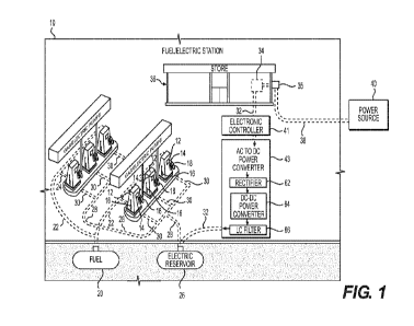
A fuel/electric station 10 (e.g. gasoline/electric station) according to the
present
invention is shown in FIGS. 1 and 2. The fuel/electric station 10 is
structured, arranged,
and designed to both dispense fuel (e.g. gas, diesel, propane, liquid propane,
hydrogen)
and recharge electric vehicles (EVs).
The fuel/electric station 10 comprises multiple fuel/electric pumps 12 (e.g.
gasoline pumps). The fuel/electric pumps 12 each comprise an electric vehicle
charger
or EV charger for recharging EVs and a fuel pump for refueling fuel type
vehicles with
fuel (e.g. gasoline, diesel, gas, propane, liquid propane, hydrogen). The
fuel/electric
pumps 12 each can comprise electrical components such as electrical components
for
charging EVs (e.g. EV charger, DC-DC converter, battery, Li-ion battery, power
storage
capacitors, fuel cells) and for refueling conventional fuel type vehicles, for
example,
having internal combustion engines (e.g. fuel pump, fuel meter, fuel filter,
electrical
control), for example, within a housing or compartment(s) of the fuel/electric
pumps 12.
The fuel/electric pumps 12 can include cooling equipment (e.g. fan,
refrigeration,
cooling circulation system), for example, to remove heat from housing,
compartments,
and electrical components.
22
CA 03189118 2023-01-06
WO 2022/031689 PCT/US2021/044321
The fuel/electric pumps 12 are shown in FIG. 1 as three (3) fuel/electric
pumps
12 per row with two (2) rows. However, more or less fuel/electric pumps 12 can
be
provided in the rows, or more or less rows can exist.
As shown in FIG. 7, the fuel/electric pumps 12 each have a display 14,
electric
charging cable 16A with an electrical connector 16B configured for EV hook up
and
recharging, a gas hose 18A fitted with a gas nozzle 18B, a DC-DC converter 60,
a
current limiter 61, and an internal Li-ion battery 19 (e.g. battery,
batteries, power storage
capacitors, fuel cells). Alternatively, the fuel/electric pumps 12 can be
structured or
configured as electric pumps configured to only charge EVs (i.e. "electric
charging only"
pumps) or structured or configured as fuel pumps configured to only pump fuel
(i.e. "fuel
filling only" pumps). The fuel pumps (e.g. gasoline pumps) can be spaced apart
from the
electric pumps comprising or consisting of EV chargers in various arrangements
and/or
locations on the premises of the fuel/electric station 10.
Again, the fuel/electric pumps 12 shown comprise the components or parts for
both pumping gas and EV charging. For example, the fuel/electrical pumps 12
can
comprise the Li-ion battery 19, power storage capacitors, fuel cells,
electronic controller
configured to control voltage and current supplied by the Li-ion battery 19 to
the electric
vehicle (EV), fuel pump components, and/or safety electronics (e.g. stop all
dispensing,
stop EV charging, stop fuel pumping, trigger HaIon fire system, electrical
spark
suppression, operational lock out detection and controls for "fuel filling
only" filling mode
or "electric charging only" charging mode).
Again, the arrangement shown in FIGS. 1 and 2, can be modified with the rows
of fuel/electric pumps 12 shown replaced with one or more rows of "fuel
filling only"
23
CA 03189118 2023-01-06
WO 2022/031689 PCT/US2021/044321
pumps and one or more rows of "electric charging only" pumps physically spaced
apart
and separate same for safety reasons (e.g. to prevent fuel vapor in proximity
to electric
equipment and potential electrical sparks). However, the fuel/electric pumps
12 can be
configured or designed to provide electric spark suppression, high level of
electrical
grounding, redundant electrical grounding, separate compartments or
containment
structures for separate gas and electric operations, air venting or air or gas
(e.g.
nitrogen) circulation pumps, fans, and/or refrigeration to allow both gas and
electric
operations within the same fuel/electric pumps 12. Again, the fuel/electric
pumps 12
can be configured or designed to only allow one mode of operation at a time,
for
example, with a time pause in-between operations to allow air venting or
circulations
pumps to remove any remaining fuel or fuel vapor to atmosphere after gas
operation
mode.
The fuel/electric station 10 comprises an underground fuel storage tank 20
connected to the individual fuel/electric pumps 12 via a main fuel supply line
22
connected to and supplying individual fuel lines 24 (i.e. fuel distribution
arrangement
and system). The fuel/electric station 10 further comprises an underground
electric
reservoir 26 connected to the individual fuel/electric pumps 12 via a main
power line 28
connected to and supplying individual electric lines 30 (i.e. electric
distribution
arrangement and system). The fuel/electric station 10 is anticipated to
provide high
speed recharging of electric vehicles (e.g. configured to recharge electrical
vehicles
(EVs) in 5 to 15 minutes) in a similar time frame to filling up a vehicle with
fuel.
As an alternative to the fuel/electric station 10 shown in FIGS. 1 and 2,
multiple
fuel tanks 20 and/or multiple electric reservoirs 26 can be provided at the
fuel/electric
24
CA 03189118 2023-01-06
WO 2022/031689 PCT/US2021/044321
station 10 to meet greater and/or peak demands. For example, the fuel/electric
station
can comprise or consist of multiple power subunits each comprising an
electrical
reservoir and multiple fuel/electric pumps 12.
The electric reservoir 26 can be an apparatus or device configured to store a
large amount of electric power. For example, the electric reservoir 26 can be
a battery,
flow battery, Li-ion battery, Li-ion battery array (e.g. banks of batteries),
power storage
capacitors (e.g. ultra capacitors) and/or fuel cells. For example, the
electric reservoir 26
can be a large flow battery or multiple Li-ion batteries (e.g. located
adjacent to the
fuel/electric pumps 12, located internally within fuel/electric pumps, and
configured to
fast charge EVs). The electric reservoir 26 can be designed, constructed, and
sized to
accommodate demand based upon the forecasted number of EVs to be recharged
hourly, daily, weekly, monthly, and yearly schedules.
The electric reservoir 26 is supplied power via underground power line 32
connected to an electric service 34 (e.g. electrical service panel), for
example, located
in store 36. A high power service line 38 supplies power from a power source
40 (e.g.
power grid, power station, transmission line, transmission station,
generator(s), fuel
generator(s), solar panel(s), wind power generator(s)). A power meter 35 (e.g.
located
on side of store 36) can be provided to meter the incoming power from the
power
source 40.
Further, an electronic controller 41 can be provided in the power line 32 for
controlling the charging of the electric reservoir 26 via the power line 32.
For example,
the electronic controller 41 can be a component or part of the electric
reservoir 26 or a
CA 03189118 2023-01-06
WO 2022/031689 PCT/US2021/044321
separate component or part (e.g. located on the premises of the fuel/electric
station 10).
The electronic controller 41, for example, can be a programmable electronic
controller.
In addition, an AC/DC converter 43 can be provided in the power line 32 for
converting the incoming AC power into DC power for charging of the electric
reservoir
26 via the power line 32, as shown in FIGS. 1 and 3. For example, the AC/DC
converter
43 can be a component or part of the electric reservoir 26 or a separate
component or
part (e.g. located on the premises of the fuel/electric station 10).
The electric reservoir 26 can be recharged in various manners. For example,
the
electric reservoir 26 is continuously charged, intermittently charge, variably
charged,
charged on demand, and/or charged according to a program or algorithm. For
example,
the charging strategy can be to charge the electric reservoir 26 in a manner
reducing or
minimizing the demand (e.g. avoiding peak demand on the power source 40) while
meeting the demand for charging the forecasted number of electric vehicles
throughout
the daily schedule. The program or algorithm can be configured to learn and
store data
on the amount of demand at a given time during each particular day throughout
the
year, season (e.g. summer, fall, winter, and spring), and holidays to update
and improve
the forecast for demand in the future.
The charging of the electric reservoir 26 can involve continuous charging the
electric reservoir 26 at an even or varying rate. Alternatively, the electric
reservoir 26
can be intermittently recharged at a fixed rate, and/or charged at different
rates at
different period of time. In any event, the intent is to structure and arrange
the
fuel/electric station 10 to provide enough power availability to always meet
peak
26
CA 03189118 2023-01-06
WO 2022/031689 PCT/US2021/044321
demands for recharging EVs at the fuel/electric station 10 while minimizing
peak power
demands on the power source 40.
The fuel/electric station 10 is shown in FIGS. 1-3, and/or another operation
(e.g.
a lot located at a different location, for example, a remote location) can be
fitted with
electrical power units 126, 226, as shown in FIG. 4. The electrical power
units 126, 226
shown are structured and arranged for providing electric recharging only;
however, the
units 126, 226 can be modify to provide both fuel refueling for conventional
fuel type
vehicles or electric recharging for EVs. The electric power units 126, 226 can
be
connected to and powered, for example, by electric panel 34 of the
fuel/electric station
10.
The portable version of electric power units 126, 226 can be portable electric
power units. For example, a 20 foot mobile storage container can be fitted
with an
electric charging only pump 12, and a 40 foot mobile storage container can be
fitted with
two (2) electric charging only pumps 12. The portable power units 126, 226 can
be
transported to a site (e.g. new station site, local station site, remote
station site), and
connected up to start operations. The portable version of the electric power
units 126,
226 can be particularly useful for providing temporary operation, remote
operation, and
provide inexpensive, reusable, or repositionable operation.
The electric reservoir 26 shown in FIGS. 1-3, for example, can be a flow
battery
50 shown in FIG. 5. Specifically, the flow battery 50 can be structured,
configured, and
or designed for use as the electric reservoir 26 in the fuel/electric station
10 shown in
FIGS. 1-3 or the portable versions of the electric power units 126 and 226
shown in FIG.
3.
27
CA 03189118 2023-01-06
WO 2022/031689 PCT/US2021/044321
The flow battery 50, for example, comprises an AQDS/AQDSH electrolyte
storage tank having a circulating pump, and an HBr/Br2 electrolyte storage
tank having
another circulating pump along with a pair of spaced apart porous carbon
electrodes
separated by a proton exchange membrane. The flow battery 50 is connected to
the
electrical supply cable 32 (electric source) and the main power supply cables
22 leading
to the fuel/electric pumps 12 to supply same.
As shown in FIG. 6, at least one DC to DC converter 60 can receive power from
the electric reservoir 26 and then supply power to the fuel/electric pumps 12.
The
converter 60 can be a component or part of the electric reservoir 26 and/or a
component or part of the fuel/electric pumps 12.
FLOW BATTERY
Again, the electric reservoir 26 can be a one or more flow batteries 50. The
open
circuit voltage of a redox flow battery cell stack is directly proportional to
the number of
stacks in series, like any other battery.
For charging an EV battery, the voltage provided by the flow battery 50 must
be
adjustable to the level to which the EV battery needs to be charged to (e.g.
may assume
several different intermediate levels during the charge process). A properly
designed
DC-DC converter 60 (e.g. housed in the fuel/electric pump 12, as shown in FIG.
7) with
appropriate sensing and feedback mechanisms, following the flow battery,
provides for
the desired voltage to charge the EV battery. For example, Tesla Model S has a
battery
voltage of approximately 350Vdc.
28
CA 03189118 2023-01-06
WO 2022/031689 PCT/US2021/044321
The voltage available from the electric reservoir 26 (e.g. flow battery 50)
itself will
depend on its configuration (i.e. number of cells in a stack, number of stacks
in series).
For instance, the following has been demonstrated with Vanadium flow batteries
installed in 2009, including 3 cell stacks with 40 cells in each stack. The
stacks are
electrically connected in series, which gives a potential of about 165 V
(Rises National
Laboratory for Sustainable Energy Report, Rises-R-1753(EN), Feb. 2011,
Technical
University of Denmark).
This voltage may be increased by adding more cell stacks in series. Another
way to increase the voltage to the desired charge level is to use a power
electronic
boost converter in the DC-DC converter 60 present at the fuel/electric pump
12. The
choice of topology to get to the desired charge voltage will depend on the
economics of
each option and the physical space (real estate) required by each option.
The output voltage of the DC-DC converter 60 will depend on the EV model
being charged, which may have vastly different battery voltages or charge port
form
factor. It is conceivable that the DC-DC converter power electronics may be
able to
provide the required voltage level for a certain range of battery voltages. If
the EV
battery voltage requirement is beyond what a single DC-DC converter 60 design
can
provide or an entirely different charge port form factor, then a different
pump type 212
will need to be provided, interfacing the same electric reservoir 26 (e.g.
flow battery 50).
Any EV battery will need to be charged at a current level recommended by its
manufacturer, which must not exceed a maximum current level to protect the EV
battery
and to limit the voltage drop in the cables connecting to the charge inlet
port on the EV.
The current limit function in the DC-DC converter 60 will provide that
protection.
29
CA 03189118 2023-01-06
WO 2022/031689 PCT/US2021/044321
If the output voltage of the electric reservoir 26 (e.g. flow battery 50) is
higher
than the EV battery voltage, then the DC-DC converter 60 will be of the "buck"
type,
consisting of either MOSFET or IGBT type power electronic switches. Due to the
high
current involved during fast charging, it would be preferred to operate the
switches with
a low loss switching approach, such as "zero-voltage switching" and
synchronous
rectification. The DC-DC converter 60 would then simply consist of the power
electronic
switches arranged in a "half-bridge" followed by a current limiter 61 (e.g. LC
filter) to
reduce the voltage ripple caused by the power electronic switching mechanism.
If the output voltage of the electric reservoir 26 (e.g. flow battery 50) is
lower than
or close to the EV battery voltage, then the DC-DC converter 60 will have a
first "boost"
stage, followed by a "DC link" capacitor, followed by a "buck" stage and the
LC filter.
The "boost" stage steps up voltage available from the flow battery to a higher
voltage,
which is then down-converted to the EV battery voltage as required during the
charge
process. The operation of both the boost and buck stage would again be done
while
minimizing the losses in the converter.
The AC-DC power converter 43 located after the AC power source 40 supplying
the electrical panel 40 or the cable 32 can incorporate a rectifier 62 stage
followed by a
DC-DC converter 64 stage. The rectifier 62 stage is needed to convert the AC
voltage to
a DC voltage. The DC-DC converter 64 or converter stage is required to convert
the
rectified (DC) voltage to the electric reservoir 26 voltage, as required
during its charging
process. The rectifier stage is typically of the full bridge "controlled
rectifier" type
implemented using MOSFET or IGBT type switches. The rectifier stage will be
controlled to achieve "power factor correction" on its AC side to meet the
power quality
CA 03189118 2023-01-06
WO 2022/031689 PCT/US2021/044321
requirement set by the utility. The DC-DC converter 64 stage may be a "buck"
type or a
"boost" followed by a "buck" type, depending on whether the flow battery
voltage is
lower or higher, respectively, than the rectified voltage. The DC-DC converter
64 stage
can include an LC filter 66 to remove the voltage ripple caused by the power
electronic
switching mechanism. Again, the power electronic switches will need to be
operated to
minimize the losses.
EV POWER PUMP HIGH ENERGY CABLE
The high energy cable16A of the fuel/electric pump 12 (FIG. 7) will be capable
of
safely delivering 350KW of power to recharge the electric vehicles. Large
copper
cables must be used to manage this much power. The power will be a combination
of
voltage and current. Electric vehicles today are being built using batteries
as high as
350-400VDC. In the future, this voltage is going to be higher to support
longer driving
distances as well as faster speeds. The charge currents are expected to be 400-
500amp5 to provide Fast Charge success.
The charge cable must be made using 0000AWG (approximately 0.5" diameter)
or larger diameter to handle the charge currents required. The interface to
the vehicle
must be large conductors also. One large cable or two smaller cables can be
used to
provide the necessary power delivery. The advantage of two cables is they
would make
it easier to handle between the EV power pump and the EV. The two cables
connection
can also be used as a safety key for the charging process. More specifically,
the EV
power pump must detect solid connections of both conductors to enable the
charge
31
CA 03189118 2023-01-06
WO 2022/031689 PCT/US2021/044321
process to begin. An "electronic safety key/lock" will also be used to insure
that the
connection to the pump is a valid EV ready to be charged. This safety key can
be part
of the pumps safety software and the EV must provide a valid response in order
for the
pump to be enabled. In this way, the pump will never turn high power on to the
cables
unless it safely and clearly determines that a valid EV is connected and ready
to charge.
The conductors between the EV power pump and the EV must be made of highly
conductive heavy gauge metal such as copper or silver and must be a low
corrosion
type. The connectors at the end of the high energy cable16A must not have any
exposed metal parts for safety purposes, and if two cables are used the cables
must be
either interchangeable or must be keyed so they cannot be improperly inserted
or
connected.
Using high conductive cables and contacts will insure minimum energy losses
during the critical charge process. It is very important that maximum energy
(i.e. power
times time) is delivered during the charge process.
Charge interruption safety will also be provided to protect against accidents
such
as a person trying to drive away during the charge process or even
environmental
accidents such as earthquakes. An Inhibit signal will be provided from the
pump that
the EV manufacturer can use to disable the EV from driving during the charge
process. But just in case the cable is accidentally pulled out of the pump
during the
charge process, the pump will detect this condition and shut power off so that
it is not
available to the outside world.
A master shut off lever will also be provided that turns power off from the
Battery
Reservoir for safety purposes.
32
CA 03189118 2023-01-06
WO 2022/031689 PCT/US2021/044321
MAXIMUM POWER SHARING
The high speed electric vehicle recharge station and system according to the
present invention can include a maximum power sharing function between
charging the
energy reservoir and charging the EV, as shown in FIG. 8.
If the electric reservoir 26 used is a Redox Flow Battery 50, it cannot be
charged
while delivering power to the output. This is because the pump flow changes
direction
accordingly. Because of this limitation, it is possible to utilize the extra
power normally
being used for charging the Redox Flow Battery to assist in charging the
actual EV.
This feature allows for relay switching for selecting a charging target.
During the
time that there is no EV at the pump, the Redox Battery can be selected and
continually
charged. As soon as the EV is ready to be charged, the system can switch the
selection over to provide maximum charge to the EV by delivering the power
that was
going to the energy reservoir to the EV.
It is noted that the charger 43' (FIG. 8) can comprise the AC TO DC POWER
CONVERTER 43 shown in FIG. 1 along with other electrical components or parts
to
configure the charger 43' for charging the electric reservoir 26.
Alternatively, the charge
43' can be a different type of charger compared to the AC TO POWER CONVERTER
43.
This type of feature can be similarly applied to the fuel/electric pump 12, as
shown in FIG. 9. The DC power from the electric reservoir 26 is directed to
the DC-DC
converter 60. The DC-DC power from the DC-DC converter 60 can be selectively
used
33
CA 03189118 2023-01-06
WO 2022/031689 PCT/US2021/044321
to charge the Li-ion battery 19 or can be used to charge the EV being charged
by the
fuel/electric pump 12. Alternatively, power from the DC-DC converter 60 and
the Li-ion
battery 19 can simultaneously be used to charge the EV due to the switching
arrangement shown in FIG. 9.
The features of FIGS. 8 and 9 can be separate or combined together into the
fuel/electric station 10.
FUEL/ELECTRIC PUMP
The fuel/electric station 10 comprises a plurality of fuel/electric pumps 12.
The
fuel/electric pumps 12 can be configured in at least three (3) basic modes,
including 1)
configured for both EV charging and fuel filling; 2) configured for EV
charging only; and
3) configured for fuel filling only.
The fuel/electric pumps 12 comprises an EV charger 12A, as shown in FIGS. 10-
13. The EV charger 12A comprises electrical components for charging an EV, for
example, a DC-DC converter.
MODULAR POWER SUBUNITS
The fuel/electric station 10 comprise one or more modular power subunits. For
example, the fuel/electric station 10 comprises four (4) modular power
subunits 2A, 2B,
2C, 2D, as shown in FIG. 14. The modular power subunits are configured to
allow one or
more addition modular power subunits to be added and installed in the
fuel/electric station
34
CA 03189118 2023-01-06
WO 2022/031689 PCT/US2021/044321
to increase the charging capacity of the fuel/electric station. For example,
the
fuel/electric station 10 can comprise one or more modular power subunits (e.g.
one (1) to
one-hundred (100) modular power subunits 2 installed at one or more
fuel/electric stations
10 located at one or more interconnected sites. For example, many modular
power
subunits can be supplied to a parking garage or interconnected parking garages
to
accommodate charging a large number or fleet of electrical vehicles.
The modular power subunits 2A, 2B, 2C, 2D can be supplied power from one or
more power sources (e.g. one or more power supply lines from power grid, power
stations, power generators, solar panels, wind power generators, power storage
facilities
or devices). For example, the modular power subunits 2A, 2B, 2C, 2D are
provided power
from four power sources 40A, 40B, 40C, 40D, as shown in FIG. 14 that are the
same
power source or different power sources.
The four (4) modular power subunits 2A, 2B, 2C, 2D, as shown in FIG. 14, are
each provided with separate electrical services 34A, 34B, 34C, 34D.
The modular power subunits 2A, 2B, 2C, 2D, for example, comprise or consist of
one or more electric reservoirs. In FIG. 14, the modular power subunits 2A,
2B, 2C, 2D
comprise, respectively, electric reservoirs 26A, 26B, 26C, 26D. The
fuel/electric pumps
12A, 12B, 12C, 12D, for example, each comprise a Li-ion battery 19 (FIG. 11).
The modular subunits, for example, are provided with various AC to DC and DC
to
DC converters to tailor power to particular components or parts of the
fuel/electric station
10. For example, a DC to DC converter is provided upstream of each electric
reservoir to
tailor charging power for the particular electric reservoirs.
CA 03189118 2023-01-06
WO 2022/031689 PCT/US2021/044321
MULTIPLE LEVELS OF ELECTRIC RESERVOIRS
The fuel/electric station 10 comprises one or more electric reservoirs. For
example,
the fuel/electric station 10 comprises, for example, a primary electric
reservoir 26-1, and
a secondary electric reservoir 26-2, as shown in FIGS. 15 and 16. As a further
example,
the fuel/electric station 10 comprises a primary electric reservoir 26-1, a
secondary
electric reservoir 26-2, and a tertiary electric reservoir 26-3, as shown in
FIGS. 15 and
16. An additional layer(s) of electric reservoirs (e.g. four or more) can be
provided at the
fuel/electric station 10 to provide the fuel/electric station 10 with
additional electric power
storage capacity, power redundancy, and power switching of one or more
electric
reservoirs to a particular fuel/electric pump 12. For example, the various
electric
reservoirs alone or in combination can be switched on to a particular
fuel/electric pump
12 to meet charging demand at the particular fuel/electric pump 12 and all
other
fuel/electric pumps in use. A computer control system is provided to monitor
the demand
at each fuel/electric pump 12 and switch appropriate power to meet the demand
of each
fuel/electric pump 12, for example, at programmed times or in real time.
COMMUNICATIONS
Communications is required between the EV Charger and the
vehicle. Communications standards have been already created for the EV
industry
such as IEC 61851-21, IEC 61851-23, IEC 61851-24, ISO 15118, PLC and more.
Hardware and software will be integrated to support one or more of these
36
CA 03189118 2023-01-06
WO 2022/031689 PCT/US2021/044321
standards to allow for proper handshaking between the EV Charger and the
vehicle. This hardware/software will support Digital communication, digitally
encoded
information exchanged between a d.c. EV charging station and an EV, as well as
the
method by which it is exchanged.
The Digital communication between the d.c. EV charging station (e.g.
fuel/electric
station 10) and an electric vehicle for control of d.c. charging is shown in
FIG. 17.
A schematic block diagram example of system A is shown in FIG. 18. The
interface circuit between the station and the electric vehicle for charging
control is
provided for digital communication with the vehicle.
37