Note: Descriptions are shown in the official language in which they were submitted.
CA 03189466 2023-01-13
WO 2022/015321
PCT/US2020/042489
PREMIXER INJECTOR ASSEMBLY IN GAS TURBINE ENGINE
BACKGROUND
[0001] An industrial gas turbine engine typically includes a compressor
section, a
turbine section, and a combustion section disposed therebetween. The
compressor
section includes multiple stages of rotating compressor blades and stationary
compressor vanes. The combustion section typically includes a plurality of
combustors. The turbine section includes multiple stages of rotating turbine
blades
and stationary turbine vanes.
[0002] The gas turbine engine may include premixer injectors for providing a
mixture of air and fuel for the combustors. The premixer injectors need to
effectively
mix the air and fuel. The premixer injectors may also need to damp out thermo-
acoustic instability. Design of premixer injectors is a challenging task that
needs to
balance among the design criteria.
BRIEF SUMMARY
[0003] In one construction, a premixer injector assembly in a gas turbine
engine,
the premixer injector assembly comprising: a premixer injector having a first
end and
a second end opposite to the first end; a fuel tube having a first plate
disposed at the
first end, a second plate disposed at the second end, and a fuel feed passage
enclosed
by an outer surface and extending between the first plate and the second
plate; a
plurality of fins coupled to the fuel tube, the plurality of fins extending
from the
outer surface of the fuel feed passage and extending between the first plate
and the
second plate, the outer surface of the fuel feed passage between adjacent fins
of the
plurality of fins comprising a concave shape; a plurality of mixing channels,
each
mixing channel of the plurality of mixing channels defined between a pair of
adjacent fins of the plurality of fins; a plurality of fuel injection
apertures disposed
along the fuel feed passage between the first plate and the second plate to
direct fuel
from the fuel feed passage to at least one mixing channel of the plurality of
mixing
channels; an air tube coupled to the fuel tube to at least partially enclose
the fuel tube
1
CA 03189466 2023-01-13
WO 2022/015321
PCT/US2020/042489
between the first end and the second end; and a plurality of air injection
openings
arranged along the air tube to inject air to the at least one mixing channel
of the
plurality of mixing channels.
[0004] In another construction, a premixer injector assembly in a gas turbine
engine, the premixer injector assembly comprising: a plurality of premixer
injectors
assembled in at least one block, each premixer injector of the plurality of
premixer
injectors comprising: a fuel tube having a first plate, a second plate, and a
fuel feed
passage enclosed by an outer surface and extending between the first plate and
the
second plate; a plurality of fins coupled to the fuel tube, the plurality of
fins
extending from the outer surface of the fuel feed passage and extending
between the
first plate and the second plate, the outer surface of the fuel feed passage
between
adjacent fins of the plurality of fins comprising a concave shape, wherein at
least a
portion of each fin of the plurality of fins is twisted along the fuel tube
forming a
helical shape; a plurality of mixing channels, each mixing channel of the
plurality of
mixing channels defined between a pair of adjacent fins of the plurality of
fins; a
plurality of fuel injection apertures disposed along the fuel feed passage
between the
first plate and the second plate to direct fuel from the fuel feed passage to
at least
one mixing channel of the plurality of mixing channels; an air tube coupled to
the
fuel tube to at least partially enclose the fuel tube; and a plurality of air
injection
openings arranged along the air tube to inject air to the at least one mixing
channel of
the plurality of mixing channels.
BRIEF DESCRIPTION OF THE DRAWINGS
[0005] To easily identify the discussion of any particular element or act, the
most
significant digit or digits in a reference number refer to the figure number
in which
that element is first introduced.
[0006] FIG. 1 is a longitudinal cross-sectional view of a gas turbine engine
taken
along a plane that contains a longitudinal axis or central axis.
[0007] FIG. 2 illustrates a section view of a combustor in a combustion
section.
[0008] FIG. 3 illustrates a perspective view of a premixer injector assembly.
2
CA 03189466 2023-01-13
WO 2022/015321
PCT/US2020/042489
[0009] FIG. 4 illustrates a perspective view of a premixer injector.
[0010] FIG. 5 illustrates a cutaway view of a fuel tube in accordance with
FIG. 4.
[0011] FIG. 6 illustrates a cutaway view of the premixer injector in
accordance with
FIG. 4.
[0012] FIG. 7 illustrates a perspective view of a premixer injector in
accordance
with one embodiment.
[0013] FIG. 8 illustrates a cutaway view of the premixer injector in
accordance with
FIG. 7.
[0014] FIG. 9 illustrates a section view of a premixer injector in accordance
with
one embodiment.
[0015] FIG. 10 illustrates a section view of a premixer injector in accordance
with
one embodiment.
[0016] FIG. 11 illustrates a section view of a premixer injector in accordance
with
one embodiment.
[0017] FIG. 12 illustrates a section view of a premixer injector in accordance
with
one embodiment.
DETAILED DESCRIPTION
[0018] Before any embodiments of the invention are explained in detail, it is
to be
understood that the invention is not limited in its application to the details
of
construction and the arrangement of components set forth in this description
or
illustrated in the following drawings. The invention is capable of other
embodiments
and of being practiced or of being carried out in various ways. Also, it is to
be
understood that the phraseology and terminology used herein is for the purpose
of
description and should not be regarded as limiting.
[0019] Various technologies that pertain to systems and methods will now be
described with reference to the drawings, where like reference numerals
represent
like elements throughout. The drawings discussed below, and the various
embodiments used to describe the principles of the present disclosure in this
patent
document are by way of illustration only and should not be construed in any
way to
3
CA 03189466 2023-01-13
WO 2022/015321
PCT/US2020/042489
limit the scope of the disclosure. Those skilled in the art will understand
that the
principles of the present disclosure may be implemented in any suitably
arranged
apparatus. It is to be understood that functionality that is described as
being carried
out by certain system elements may be performed by multiple elements.
Similarly,
for instance, an element may be configured to perform functionality that is
described
as being carried out by multiple elements. The numerous innovative teachings
of the
present application will be described with reference to exemplary non-limiting
embodiments.
[0020] Also, it should be understood that the words or phrases used herein
should
be construed broadly, unless expressly limited in some examples. For example,
the
terms "including," "having," and "comprising," as well as derivatives thereof,
mean
inclusion without limitation. The singular forms "a", "an" and "the" are
intended to
include the plural forms as well, unless the context clearly indicates
otherwise.
Further, the term "and/or" as used herein refers to and encompasses any and
all
possible combinations of one or more of the associated listed items. The term
"or" is
inclusive, meaning and/or, unless the context clearly indicates otherwise. The
phrases "associated with" and "associated therewith," as well as derivatives
thereof,
may mean to include, be included within, interconnect with, contain, be
contained
within, connect to or with, couple to or with, be communicable with, cooperate
with,
interleave, juxtapose, be proximate to, be bound to or with, have, have a
property of,
or the like. Furthermore, while multiple embodiments or constructions may be
described herein, any features, methods, steps, components, etc. described
with
regard to one embodiment are equally applicable to other embodiments absent a
specific statement to the contrary.
[0021] Also, although the terms "first", "second", "third" and so forth may be
used
herein to refer to various elements, information, functions, or acts, these
elements,
information, functions, or acts should not be limited by these terms. Rather
these
numeral adjectives are used to distinguish different elements, information,
functions
or acts from each other. For example, a first element, information, function,
or act
could be termed a second element, information, function, or act, and,
similarly, a
4
CA 03189466 2023-01-13
WO 2022/015321
PCT/US2020/042489
second element, information, function, or act could be termed a first element,
information, function, or act, without departing from the scope of the present
disclosure.
[0022] In addition, the term "adjacent to" may mean: that an element is
relatively
near to but not in contact with a further element; or that the element is in
contact
with the further portion, unless the context clearly indicates otherwise.
Further, the
phrase "based on" is intended to mean "based, at least in part, on" unless
explicitly
stated otherwise. Terms "about" or "substantially" or like terms are intended
to
cover variations in a value that are within normal industry manufacturing
tolerances
for that dimension. If no industry standard is available, a variation of
twenty percent
would fall within the meaning of these terms unless otherwise stated.
[0023] FIG. 1 illustrates an example of a gas turbine engine 100 including a
compressor section 102, a combustion section 104, and a turbine section 106
arranged along a central axis 112. The compressor section 102 includes a
plurality
of compressor stages 114 with each compressor stage 114 including a set of
rotating
blades 116 and a set of stationary vanes 118 or adjustable guide vanes. A
rotor 134
supports the rotating blades 116 for rotation about the central axis 112
during
operation. In some constructions, a single one-piece rotor 134 extends the
length of
the gas turbine engine 100 and is supported for rotation by a bearing at
either end. In
other constructions, the rotor 134 is assembled from several separate spools
that are
attached to one another or may include multiple disk sections that are
attached via a
bolt or plurality of bolts.
[0024] The compressor section 102 is in fluid communication with an inlet
section
108 to allow the gas turbine engine 100 to draw atmospheric air into the
compressor
section 102. During operation of the gas turbine engine 100, the compressor
section
102 draws in atmospheric air and compresses that air for delivery to the
combustion
section 104. The illustrated compressor section 102 is an example of one
compressor
section 102 with other arrangements and designs being possible.
[0025] In the illustrated construction, the combustion section 104 includes a
plurality of separate combustors 120 that each operate to mix a flow of fuel
with the
CA 03189466 2023-01-13
WO 2022/015321
PCT/US2020/042489
compressed air from the compressor section 102 and to combust that air-fuel
mixture
to produce a flow of high temperature, high pressure combustion gases or
exhaust
gas 122. Of course, many other arrangements of the combustion section 104 are
possible.
[0026] The turbine section 106 includes a plurality of turbine stages 124 with
each
turbine stage 124 including a number of rotating turbine blades 126 and a
number of
stationary turbine vanes 128. The turbine stages 124 are arranged to receive
the
exhaust gas 122 from the combustion section 104 at a turbine inlet 130 and
expand
that gas to convert thermal and pressure energy into rotating or mechanical
work. The turbine section 106 is connected to the compressor section 102 to
drive
the compressor section 102. For gas turbine engines 100 used for power
generation
or as prime movers, the turbine section 106 is also connected to a generator,
pump,
or other device to be driven. As with the compressor section 102, other
designs and
arrangements of the turbine section 106 are possible.
[0027] An exhaust portion 110 is positioned downstream of the turbine section
106
and is arranged to receive the expanded flow of exhaust gas 122 from the final
turbine stage 124 in the turbine section 106. The exhaust portion 110 is
arranged to
efficiently direct the exhaust gas 122 away from the turbine section 106 to
assure
efficient operation of the turbine section 106. Many variations and design
differences are possible in the exhaust portion 110. As such, the illustrated
exhaust
portion 110 is but one example of those variations.
[0028] A control system 132 is coupled to the gas turbine engine 100 and
operates
to monitor various operating parameters and to control various operations of
the gas
turbine engine 100. In preferred constructions the control system 132 is
typically
micro-processor based and includes memory devices and data storage devices for
collecting, analyzing, and storing data. In addition, the control system 132
provides
output data to various devices including monitors, printers, indicators, and
the like
that allow users to interface with the control system 132 to provide inputs or
adjustments. In the example of a power generation system, a user may input a
power
6
CA 03189466 2023-01-13
WO 2022/015321
PCT/US2020/042489
output set point and the control system 132 may adjust the various control
inputs to
achieve that power output in an efficient manner.
[0029] The control system 132 can control various operating parameters
including,
but not limited to variable inlet guide vane positions, fuel flow rates and
pressures,
engine speed, valve positions, generator load, and generator excitation. Of
course,
other applications may have fewer or more controllable devices. The control
system
132 also monitors various parameters to assure that the gas turbine engine 100
is
operating properly. Some parameters that are monitored may include inlet air
temperature, compressor outlet temperature and pressure, combustor outlet
temperature, fuel flow rate, generator power output, bearing temperature, and
the
like. Many of these measurements are displayed for the user and are logged for
later
review should such a review be necessary.
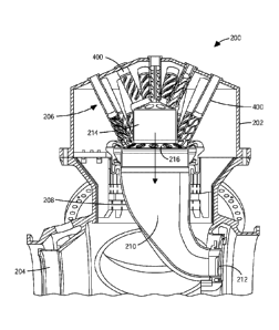
[0030] FIG. 2 illustrates a section view of a combustor 200. The combustor 200
includes a casing 202, an inlet 204, a premixer injector assembly 206, a
combustor
liner 208 defining a combustor chamber 210 and a chamber exit 212. The casing
202
encloses the premixer injector assembly 206 and the combustor liner 208. The
premixer injector assembly 206 is disposed upstream of the combustor chamber
210.
[0031] The premixer injector assembly 206 includes a plurality of premixer
injectors 400. The premixer injectors 400 are assembled in at least one block.
As
illustrated in FIG. 2, a number of the premixer injectors 400 are assembled in
a
primary block 214 and a remaining number of the premixer injectors 400 are
assembled in a secondary block 216. The primary block 214 is disposed upstream
of
the secondary block 216. The premixer injectors 400 are not parallel to each
other.
The premixer injectors 400 are oblique to the general flow direction indicated
by the
arrow. It is understood that the premixer injectors 400 may be assembled in
the
primary block 214 and secondary block 216 in other configurations, such as
parallel
to each other, or perpendicular to the primary block 214 or perpendicular to
the
secondary block 216.
[0032] In operation of the gas turbine engine 100, air from the compressor
section
102 enters the combustor 200 through the inlet 204 and is injected to the
premixer
7
CA 03189466 2023-01-13
WO 2022/015321
PCT/US2020/042489
injectors 400. Fuel from a fuel source (not shown) enters the premixer
injectors 400.
Air and fuel are mixed in the premixer injectors 400. The mixture of air and
fuel
enters the combustor chamber 210, as indicated by the arrow line, and is
ignited in
the combustor chamber 210. The ignited mixture of air and fuel exits the
combustor
chamber 210 through the chamber exit 212 and enters the turbine section 106.
[0033] FIG. 3 illustrates a perspective view of a premixer injector assembly
300.
The premixer injector assembly 300 includes a plurality of premixer injectors
400.
As illustrated in FIG. 3, the plurality of premixer injectors 400 are all
assembled in a
single block 302. The plurality of premixer injectors 400 are parallel to each
other.
The plurality of premixer injectors 400 are perpendicular to the single block
302.
The plurality of premixer injectors 400 are arranged in the single block 302
and
spaced apart from each other. The plurality of premixer injectors 400 may be
equally
spaced apart from each other. The single block 302 has a circular shape. It is
understood that the single block 302 may have other geometric shapes, such as
oval,
square, rectangular, etc. It is also understood that the plurality of premixer
injectors
400 may be assembled in the single block 302 in other configurations, such as
not
parallel to each other, or not perpendicular to the single block 302, etc. The
premixer
injector assembly 300 shown in FIG. 3 is easy to assemble.
[0034] FIG. 4 illustrates a perspective view of one of the premixer injectors
400
suitable for use in the arrangements illustrated in FIGS. 2-3. The premixer
injector
400 has a first end 406 and a second end 408 opposite to the first end 406.
The
premixer injector 400 includes an air tube 402 and a fuel tube 500. The air
tube 402
and the fuel tube 500 extend between the first end 406 and the second end 408.
The
air tube 402 at least partially encloses the fuel tube 500. A portion of the
fuel tube
500 extends out of the air tube 402 at the second end 408. In other
embodiments, the
fuel tube 500 may also be recessed in the air tube 402. The air tube 402 and
the fuel
tube 500 may be manufactured as two separate components. The air tube 402 and
the
fuel tube 500 are then assembled together to form the premixer injector 400.
The air
tube 402 and the fuel tube 500 may be manufactured as a single component
forming
the premixer injector 400.
8
CA 03189466 2023-01-13
WO 2022/015321
PCT/US2020/042489
[0035] The air tube 402 includes at least one air injection opening 404
disposed
along the air tube 402 and extending between the first end 406 and the second
end
408. The air injection opening 404 perforates the air tube 402. The air
injection
opening 404 has a helical shape. The air injection opening 404 is twisted
between the
first end 406 and the second end 408 forming the helical shape. As shown in
FIG. 4,
the air injection opening 404 has a uniform width between the first end 406
and the
second end 408. However, the air injection openings may be wider toward the
first
end 406 and narrower towards the second end 408 or vise verse.
[0036] The air tube 402 may include a plurality of air injection openings 404.
As
illustrated in FIG. 4, the air tube 402 includes four air injection openings
404. The
four air injection openings 404 are arranged on the air tube 402 and are
equally
spaced apart from each other. Each of the four air injection openings 404 has
a
helical shape and is twisted between the first end 406 and the second end 408.
The
four air injection openings 404 are parallel to each other. However, the air
injection
openings 404 may not be parallel to each other. The air tube 402 may include
any
numbers of air injection openings 404, for example, two air injection openings
404,
three air injection openings 404, five air injection openings 404, six air
injection
openings 404, etc.
[0037] FIG. 5 illustrates a cutaway view of the fuel tube 500 in accordance
with
FIG. 4. The fuel tube 500 includes a first plate 502 disposed at the first end
406, a
second plate 504 disposed at the second end 408, and a fuel feed passage 506
extending between the first plate 502 and the second plate 504. The fuel feed
passage
506 is enclosed by an outer surface 514. The first plate 502 has an orifice
516 to feed
fuel from a fuel source (not shown) to the fuel feed passage 506.
[0038] The fuel tube 500 includes a plurality of fuel injection apertures 508
disposed along the fuel feed passage 506 between the first plate 502 and the
second
plate 504. The fuel injection apertures 508 perforate the outer surface 514 of
the fuel
feed passage 506 to direct the fuel out of the fuel feed passage 506.
[0039] The fuel tube 500 includes at least one fin 510 coupled to the fuel
tube 500.
The fin 510 extends outward from the outer surface 514 of the fuel feed
passage 506.
9
CA 03189466 2023-01-13
WO 2022/015321
PCT/US2020/042489
The fin 510 extends along the fuel tube 500 between the first plate 502 and
the
second plate 504. The fin 510 has a helical shape. The helical shaped fin 510
is
twisted between the first plate 502 and the second plate 504.
[0040] The fuel tube 500 may include a plurality of fins 510. As illustrated
in the
cutaway view of FIG. 5, the fuel tube 500 includes four fins 510 (three fins
510 are
visible in FIG. 5, four fins 510 are shown in FIG. 6). The four fins 510 are
arranged
on the outer surface 514 of the fuel feed passage 506 and are equally spaced
apart
from each other. Each of the four fins 510 has a helical shape and is twisted
between
the first plate 502 and the second plate 504. The four fins 510 are parallel
to each
other. However, the fins 510 may not be parallel to each other. The fuel tube
500
may include any numbers of fins 510, for example, two fins 510, three fins
510, five
fins 510, or six fins 510, etc.
[0041] A mixing channel 512 is defined between a pair of adjacent fins 510.
The
outer surface 514 of the fuel feed passage 506 between adjacent fins 510 has a
concave shape.
[0042] FIG. 6 illustrates a cutaway view of the premixer injector 400 in
accordance
with FIG. 4. The air tube 402 is cutaway to illustrate the fuel tube 500
disposed in
the air tube 402.
[0043] The fuel tube 500 includes four fins 510 that each extend from the
outer
surface 514 of the fuel feed passage 506 to the air tube 402. Four mixing
channels
512 are defined between four pairs of adjacent fins 510 and between the air
tube 402
and the outer surface 514 of the fuel feed passage 506. The four mixing
channels 512
are independent from each other and are separated by fins 510. The number of
the
fins 510 and the number of mixing channels 512 are designed to meet the
requirement of the particular engine in which they are used. In preferred
constructions, the number of fins 510 matches the number of air injection
openings
404 and the helical twist of the fins 510 matches that of the air injection
openings
404. Of course, other arrangements are possible.
[0044] In operation of the gas turbine engine 100, air from the compressor
section
102 enters at least one mixing channel 512 through the air injection opening
404.
CA 03189466 2023-01-13
WO 2022/015321
PCT/US2020/042489
Fuel from the fuel feed passage 506 is directed to at least one mixing channel
512
through the fuel injection apertures 508. The air and fuel are mixed in the
mixing
channel 512 and swirled in the mixing channel 512 along the helical shape of
the fins
510. A swirl flow of the mixture of air and fuel is induced at the second end
408 of
the premixer injector 400. A strength of the swirl flow of the mixture of air
and fuel
is defined by a tangential component of a velocity the mixture of air and fuel
exiting
the premixer injector 400. The strength of the swirl flow of the mixture of
air and
fuel is controlled by a twist angle of the helix of the fins 512. The swirl
flow of the
mixture of air and fuel is discharged directly to the combustor chamber 210.
[0045] In operation of the gas turbine engine 100, air may be unevenly fed to
the
premixer injector 400. For example, air may be preferably coming from the top
of
the air tube 402. The premixer injector 400 is designed such that for a given
twist
length of the air injection openings 404 along the air tube 402, if the twist
angle of
the air injection openings 404 is sufficiently high, all mixing channels 512
are
exposed to the top and under fed side of the air injection openings 404.
Thereby, all
mixing channels 512 receive the same amount of air.
[0046] Parameters of the helix are designed to meet requirement of the swirl
flow of
the mixture of the air and fuel at entry of the combustor chamber 210. The
parameters of the helix include a pitch of the helix, a twist angle of the
helix, etc. For
example, a twist angle of the fin 510 between the first plate 502 and the
second plate
504 may be 90 , 180 , 360 , 450 , or any suitable angles, etc. A twist angle
of the fin
510 may be the same as a twist angle of the air injection opening 404. A pitch
of the
fin 510 may be the same as a pitch of the air injection opening 404. It is
understood
that a twist angle of the fin 510 may be different from a twist angle of the
air
injection opening 404. It is also understood that a pitch of the fin 510 may
be
different from a pitch of the air injection opening 404. The fin 510 showed in
FIG. 6
has a non-zero twist angle between the first plate 502 and the second plate
504 which
results in a helical shape fin 510 between the first plate 502 and the second
plate 504.
However, the twist angle of the fin 510 could be zero which results in a
straight
shape fin 510 between the first plate 502 and the second plate 504.
11
CA 03189466 2023-01-13
WO 2022/015321
PCT/US2020/042489
[0047] FIG. 7 illustrates a perspective view of another premixer injector 700.
The
premixer injector 700 can be used in place of the premixer injector 400 or can
be
used in conjunction with the premixer injector 400.
[0048] The premixer injector 700 includes an air tube 402 and a fuel tube 500.
The
air tube 402 at least partially encloses the fuel tube 500. The premixer
injector 700
has at least one air injection opening 404 disposed along the air tube 402 and
extending between the first end 406 and the second end 408. The air injection
opening 404 has a straight shape between the first end 406 and the second end
408.
[0049] The air tube 402 may include a plurality of air injection openings 404.
As
illustrated in FIG. 7, the air tube 402 includes four air injection openings
404
disposed along the air tube 402 and extending between the first end 406 and
the
second end 408. The four air injection openings 404 are arranged on the air
tube 402
and are equally spaced apart from each other. Each of the four air injection
openings
404 has a straight shape between the first end 406 and the second end 408. It
is
understood that the air tube 402 may include any numbers of air injection
openings
404, for example, two air injection openings 404, three air injection openings
404,
five air injection openings 404, six air injection openings 404, etc.
[0050] FIG. 8 illustrates a cutaway view of the premixer injector 700 in
accordance
with FIG. 7. The fuel tube 500 includes a plurality of fuel injection
apertures 508
disposed along the fuel feed passage 506between the first plate 502 and the
second
plate 504. The fuel injection apertures 508 perforate the outer surface 514 of
the fuel
feed passage 506 to direct the fuel out of the fuel feed passage 506.
[0051] The fuel tube 500 includes at least one fin 510 coupled to the fuel
tube 500.
The fin 510 extends outward from the outer surface 514 of the fuel feed
passage 506.
The fin 510 extends between the first plate 502 and the second plate 504. The
fin 510
has a straight shape between the first plate 502 to an intermediate point 802.
The fin
510 is twisted between the intermediate point 802 and the second plate 504,
thereby
forming a helical shape. The intermediate point 802 is defined between the
first plate
502 and the second plate 504. The intermediate point 802 may be disposed close
to
the second plate 504.
12
CA 03189466 2023-01-13
WO 2022/015321
PCT/US2020/042489
[0052] Parameters of the helix are designed to meet requirement of the swirl
flow of
the mixture of the air and fuel at an entry of the combustor 200. For example,
the
twist angle of the fin 510 between the intermediate point 802 and the second
plate
504 may be 450, 90% 180% 270% or any suitable angles, etc.
[0053] The fuel tube 500 may include a plurality of fins 510. As illustrated
in the
cutaway view of FIG. 8, the fuel tube 500 includes four fins 510. The four
fins 510
are arranged on the outer surface 514 of the fuel feed passage 506 and are
equally
spaced apart from each other. Each of the four fins 510 has a straight shape
between
the first plate 502 to the intermediate point 802 and is twisted between the
intermediate point 802 and the second plate 504. It is understood that the
fuel tube
500 may include any numbers of fins 510, for example, two fins 510, three fins
510,
five fins 510, or six fins 510, etc.
[0054] A mixing channel 512 is defined between a pair of adjacent fins 510.
The
outer surface 514 between adjacent fins 510 has a concave shape. The concave
shape
includes a continuous curve that tangentially intersects each fin 510 of the
adjacent
fins 510 that defines the mixing channel 512. In another construction, the
concave
shape includes a single continuous curve that extends from a tip of one fin
510 to a
tip of an adjacent fin 510 (e.g., a hyperbola). As illustrated in the cutaway
view of
FIG. 8, four mixing channels 512 are defined between four pairs of adjacent
fins 510
and between the air tube 402 and the outer surface 514 of the fuel feed
passage 506.
The four mixing channels 512 are independent from each other and are separated
by
fins 510. The number of the fins 510 and the number of mixing channels 512 are
designed to meet the requirement of the mixture at entry of the combustor
chamber
210.
[0055] FIG. 9 illustrates a section view of a premixer injector 900. The
arrangement
of the premixer injector 900 illustrated in FIG. 9 can be used in the premixer
injector
400 or in the premixer injector 700.
[0056] Each air injection opening 404 is positioned between a pair of adjacent
fins
510. The injection opening 404 is positioned along a center of one of the
mixing
channel 512 defined by the pair of adjacent fins 510. However, the air
injection
13
CA 03189466 2023-01-13
WO 2022/015321
PCT/US2020/042489
opening 404 could be positioned off-center of the mixing channel 512. For
example,
the air injection opening 404 could be positioned along the edge of one fin
510 of the
pair of adjacent fins 510. FIG. 9 shows that the air injection opening 404 has
a
uniform width from an outer surface of the air tube 402 to an inner surface of
the air
tube 402. However, the air injection opening 404 may have a fillet on the
outer
surface of the air tube 402. The air injection opening 404 may have a tapered
shape
from the outer surface of the air tube 402 to the inner surface of the air
tube 402. Air
enters each mixing channel 512 through one air injection opening 404. Fuel
enters
each mixing channel 512 from the fuel feed passage 506 through two fuel
injection
apertures 508. As illustrated in FIG. 9, the fuel injection apertures 508 are
perforated
through the outer surface 514 of the fuel feed passage 506 in radial
directions.
However, it is understood that other arrangements are possible.
[0057] Air impinges on the outer surface 514 of the fuel feed passage 506 and
creates a pair of counter-rotating vortices in each mixing channel 512. The
pair of
counter-rotating vortices mixes with the fuel in each mixing channel 512. Air
and
fuel are effectively mixed in each mixing channel 512. The mixture of air and
fuel is
discharged directly to the combustor chamber 210 with a swirl induced by the
helical
shaped fins 510.
[0058] A pair of counter-rotating vortices is created in each mixing channel
512.
The outer surface 514 of the fuel feed passage 506 in which air is impinged on
has a
concave shape. The concave shaped impingement surface enables a stable flow
configuration of the pair of counter-rotating vortices.
[0059] FIG. 10 illustrates a section view of a premixer injector 1000. The
arrangement of the premixer injector 1000 illustrated in FIG. 10 can be used
in the
premixer injector 400 or in the premixer injector 700.
[0060] Each air injection opening 404 is positioned along each fin 510 and is
bisected by each fin 510. Air enters two adjacent mixing channels 512 through
one
bisected air injection opening 404. Of course, when using this arrangement,
the air
injection openings 404 are somewhat larger than those illustrated in the
arrangement
of Fig. 9 as the fin 510 effectively blocks a portion of the air injection
opening 404.
14
CA 03189466 2023-01-13
WO 2022/015321
PCT/US2020/042489
Fuel enters each mixing channel 512 from the fuel feed passage 506 through at
least
one fuel injection aperture 508. A pair of counter-rotating vortices is
created in each
mixing channel 512. FIG. 10 shows each air injection opening 404 is positioned
along each fin 510 and is bisect by each fin 510. However, it could be
understood
that each air injection opening 404 is positioned along an alternative fin 510
and is
bisect by the alternative fin 510.
[0061] FIG. 11 illustrates a section view of a premixer injector 1100. The
arrangement of the premixer injector 1100 illustrated in FIG. 11 can be used
in the
premixer injector 400 or in the premixer injector 700.
[0062] Each air injection opening 404 is positioned between a pair of adjacent
fins
512. The air injection opening 404 is positioned along a center of each mixing
channel 512 defined by the pair of adjacent fins 510. However, the injection
opening
404 could be positioned off-center of the mixing channel 512. Air enters each
mixing
channel 512 through one air injection opening 404. Fuel enters each mixing
channel
512 from the fuel feed passage 506 through at least one fuel injection
aperture 508.
A pair of counter-rotating vortex is created in each mixing channel 512.
[0063] FIG. 12 illustrates a section view of a premixer injector 1200. The
arrangement of the premixer injector 1200 can be used in the premixer injector
400
or in the premixer injector 700.
[0064] Each air injection opening 404 is positioned along each fin 510 and is
bisected by each fin 510. Air enters two adjacent mixing channels 512 through
one
bisected air injection opening 404. Fuel enters each mixing channel 512 from
the fuel
feed passage 506 through two fuel injection apertures 508. A pair of counter-
rotating
vortex is created in each mixing channel 512.
[0065] Configurations of the premixer injector 900, or the premixer injector
1000,
or the premixer injector 1100, or the premixer injector 1200 may be combined
by
different configurations thereof. The premixer injector 400 or the premixer
injector
700 may have any configuration of the premixer injector 900, the premixer
injector
1000, the premixer injector 1100, or the premixer injector 1200, or any
combinations
thereof.
CA 03189466 2023-01-13
WO 2022/015321
PCT/US2020/042489
[0066] The premixer injectors 400 or the premixer injectors 700 effectively
and
rapidly mix air and fuel upstream of the combustor chamber 210 by a pair of
stable
counter-rotating vortices created in each mixing channel 512. The pair of
stable
counter-rotating vortices is created by the concave shaped outer surface 514
of the
fuel feed passage 506. The effectively mixed air and fuel provide a uniform
mixture
composition to the combustor chamber 210. The premixer injector 400 or
premixer
injector 700 is robust against uneven air feeds which ensures the uniform
mixture
composition across the mixing channels 512. The uniform composition of the air
and
fuel reduces nitrogen oxides emissions from the combustor chamber 210.
[0067] The premixer injectors 400 or the premixer injectors 700 induce a swirl
flow
of the mixture of the air and fuel at the second end 408 of the premixer
injector 400
or the premixer injector 700 to stabilize flames in the combustor chamber 210.
The
swirl flow of the mixture of the air and fuel is induced by the helical shaped
fins 510
which may eliminate placing additional protruding swirler bodies downstream of
the
fuel injection apertures 508. The premixer injector 400 or premixer injector
700
provides a mixing channel 512 having an aerodynamic property that reduces low
velocity zones in the mixing channel 512 due to boundary layers, wakes of the
additional protruding swirler bodies, etc., which reduces occurrence of
flashback and
auto-ignition. The premixer injector 400 or premixer injector 700 provides a
robust
vortex-breakdown anchored flames for flame stability and turndown capability.
[0068] The air injection openings 404 and the fuel injection apertures 508 of
the
premixer injector 400 or the premixer injector 700 are arranged and
distributed along
the premixer injector 400 or the premixer injector 700. Air progressively
enters the
mixing channels 512 through the air injection openings 404 to damp fuel-air
ratio
fluctuations at an outlet of the premixer injector 400 or the premixer
injector 700,
which reduces thermo-acoustic instability in the combustion chamber 210. Fuel-
air-
ratio (FAR) muffling is thus achieved.
[0069] The premixer injector 400 or premixer injector 700 can use gas fuel or
liquid
fuel. The premixer injector 400 or premixer injector 700 can be fit with a
diesel lane
for direct lean injection of liquid fuel in the combustor chamber 210 which
enables
16
CA 03189466 2023-01-13
WO 2022/015321
PCT/US2020/042489
dry-liquid dual-fuel operation. The premixer injector 400 or premixer injector
700
can accommodate a variety of liquid fuel injectors, such as a plain jets in
cross flow
downstream of the premixer injector 400 or premixer injector 700, or close to
outlet
of the premixer injector 400 or premixer injector 700 to hide the liquid
injection
holes from the flame to reduce radiative heating and coking, or pressure-swirl
atomizers, or any other configurations sufficiently small to be integrated
within the
tip of the premixer injector 400 or premixer injector 700. The liquid fuel can
be
injected in an upstream part of the fuel tube 500 to obtain lean-premixed
flames in
the combustor chamber 210.
[0070] The premixer injector 400 or premixer injector 700 is easy to
manufacture
and easy to assemble. The premixer injector 400 or premixer injector 700 can
be
scaled by numbers or geometrically or both to be used in different gas turbine
engines which creates a commonality of component and cost reduction.
[0071] Although an exemplary embodiment of the present disclosure has been
described in detail, those skilled in the art will understand that various
changes,
substitutions, variations, and improvements disclosed herein may be made
without
departing from the spirit and scope of the disclosure in its broadest form.
[0072] None of the description in the present application should be read as
implying
that any particular element, step, act, or function is an essential element,
which must
be included in the claim scope: the scope of patented subject matter is
defined only
by the allowed claims. Moreover, none of these claims are intended to invoke a
means plus function claim construction unless the exact words "means for" are
followed by a participle.
17