Note: Descriptions are shown in the official language in which they were submitted.
CA 03189555 2023-01-16
WO 2022/015373
PCT/US2021/018192
TITLE
HIGH STRENGTH MULTI-USE HOSE
CROSS REFERENCE TO RELATED APPLICATIONS
[0001] This application claims priority to United States Utility Patent
Application No.
17/176,491 filed on February 16, 2021, and United States Provisional Patent
Application No.
63/052,549 filed on July 16, 2020, each of which is incorporated by reference
herein.
TECHNICAL FIELD
[0002] The present invention relates to flexible hoses designed to
withstand tensile loads
while delivering high volumes of fluids over long distances (e.g., greater
than 100 m) and,
more particularly, to a large diameter, round-cross-sectional hose¨as well as
a method of
making the same¨having woven, continuous strand, para- and meta- aramid blend
yarn with
thermoplastic polyurethane (TPU) extruded through the weave so as to promote
specific
levels of penetration or "pillaring" within the jacket by the TPU, resulting
in a single-ply
construction (i.e., no layering of separate materials) so that the TPU is
exposed to the fluid
flowing through the hose and the ambient environment on its opposing side.
This hose will
have particular utility in agricultural applications, but could also be used
as a feeder hose, in
marine, military, mining, and/or other settings where ice or internal
abrasions present unique
challenges.
1
CA 03189555 2023-01-16
WO 2022/015373
PCT/US2021/018192
BACKGROUND
[0003] Hoses
having long lengths require a unique blend of strength and capacity. By
definition, these hollow tubular structures include a cylindrical wall
defining a fluid passage.
That wall must possess sufficient structural integrity in the face of pressure
exerted by the
fluid being transported by that hose, while simultaneously being durable and
flexible enough
to allow the hose to be handled and transported. Hoses that are capable of
delivering high
capacity (i.e., larger diameter) over significant distances (i.e., length of
300 feet or more) are
particularly useful. However, material costs, weight of the hose, and
strength/ability to
withstand both internally exerted pressure and external forces/abrasions are
all significant
considerations that must be further balanced by the length of the hose needed,
especially in
operations where it may be impractical to couple together smaller sections of
individual
hoses.
[0004] As an
example, agricultural hoses typically come in minimal lengths of about 330
feet (-100 m) and often up to 660 feet (-200 m) to allow for the conveyance of
fluids over
long distances, as may be encountered in a planting field or farming
operation. The diameter
of these hoses (and, by extension the volume of fluid delivered therein) is
significantly larger
than most other hose types, with preferred diameters of greater than 4 inches
(-10 cm) and
possibly approaching 8 to 9 inches (-20 to 23 cm) or even up to 12 to 16
inches (-30 to 40
cm). Nevertheless, agriculturual and other strong, high capacity hoses must be
flexible so as
to accommodate storage, frequent repositioning, and use changing environments
and terrains
where less flexible solutions (e.g., metallic or rigid tubing) is impractical.
[0005]
Agricultural and other high strength and capacity hoses (e.g., for use in
marine,
military, mining, construction, water/food, and other industrial applications)
must also be
durable. Foremost, the outer facings of the hose must be resistant to cuts,
punctures, and
abrasions, as these hoses are often dragged over rough terrain and/or through
rocky/jagged
2
CA 03189555 2023-01-16
WO 2022/015373
PCT/US2021/018192
bore holes and other confined spaces on a regular basis. Owing to potentially
exponentially
larger volumes of pressurized fluid carried within large diameter hoses (as
compared to
smaller diameter hoses), these hoses must also possess tensile ratio of at
least 2:1 (i.e., the
tensile load capability of the hose in comparison to the weight of the fluid
along a given
length of the hose). Further still, these hoses must be a single, unitary
construction, as
coupling together smaller high strength hoses is impractical owing to the cost
of the
couplings and multiplicity of potential failure points such arrangements
necessarily entail.
[0006] The
strength of a large diameter, high capacity hose can be qualitatively
reflected
by its resistance to delamination. That is, most hoses employ multiple layers.
Repeated stress
to the hose structure over time will eventually cause the outer-most
layer/jacket to "bubble"
or delaminate, thereby signaling a future/imminent failure.
[0007] United
States Patent 8,746,289 describes a spoolable pipe with a layered
construction. The disclosed pipe can be negatively buoyant, corrosion-
resistant, and light
weight.
[0008] United
States Patent 7,588,056 discloses methods and systems for a flexible hose
including a core tube made of fluid-impervious materials. An aramid sleeve,
woven with an
open or closed mesh, circumferentially covers this core tube. The core tube is
specifically
formed to have a smooth-bore finish along its inner surface.
[0009] United
States Patent 6,857,452 contemplates a laminate-constructed, spoolable
tube. The tube includes a fiber composite layer with a unique triaxial braid
construction.
[0010] Korean
Patent 1019910014641A describes a non-metallic, corrosion-resistant
conduit. Circumferentially spaced helical strengthening ribs are provided
along a plastic liner.
Methods of making this type of conduit are also provided.
[0011]
Separately, All-American Hose LLC (Union City, PA) sells a number of
agricultural hoses, including under its branded line of TSX hoses. These hoses
rely upon TPU
3
CA 03189555 2023-01-16
WO 2022/015373
PCT/US2021/018192
extruded through a polyester weave, with diameters ranging from 4.5 to 7.25
inches (-11 to
18.5 cm). Other known competitive agricultural hoses attempt to mimic this
construction,
although all of these hoses tend to have tensile strengths of about 30,000 to
75,000 pounds
and weights between 1.30 to 2.30 pounds per foot (. 0.180 to 0.319 kg/m).
[0012] In view
of the foregoing, a large diameter (i.e., > 4 inches) and long-length (i.e., >
300 ft.) hose having sufficient strength and capcity would be welcome.
Specifically, such a
hose having greater than 2:1 tensile ratio and/or exceeding 100,000 pounds
(and, more
ideally, 140,000 pounds) of tensile strength would be welcome.
SUMMARY OF INVENTION
[0013] A single
ply, high strength and high capacity hose is contemplated. A
thermoplastic polymer, such as polyurethane, is extruded through a woven mesh
of aramid
fibers so as to encourage pillaring through gaps in the mesh of a sufficient
amount to improve
the overall durability and strength of the resultant hose. This wide diameter
hose (at least 4
inches and up to 9, 12, or even 16 inches) exhibits tensile ratios in excess
of 2:1 while being
capable of withstanding tensile loads in excess of 100,000 pounds.
[0014] Still
other aspects of the invention are disclosed and discernible to those having
skill in this field. In this regard, specific reference is made to the
appended claims, drawings,
and description below, all of which disclose elements of the invention. While
specific
embodiments are identified, it will be understood that elements from one
described aspect
may be combined with those from a separately identified aspect. In the same
manner, a
person of ordinary skill will have the requisite understanding of common
processes,
components, and methods, and this description is intended to encompass and
disclose such
common aspects even if they are not expressly identified herein.
4
CA 03189555 2023-01-16
WO 2022/015373
PCT/US2021/018192
DESCRIPTION OF THE DRAWINGS
[0015] Operation of the invention may be better understood by reference to
the detailed
description taken in connection with the following illustrations. These
appended drawings
form part of this specification, and any information on/in the drawings is
both literally
encompassed (i.e., the actual stated values) and relatively encompassed (e.g.,
ratios for
respective dimensions of parts). In the same manner, the relative positioning
and relationship
of the components as shown in these drawings, as well as their function,
shape, dimensions,
and appearance, may all further inform certain aspects of the invention as if
fully rewritten
herein. Unless otherwise stated, all dimensions in the drawings are with
reference to inches,
and any printed information on/in the drawings form part of this written
disclosure.
[0016] In the drawings, which are incorporated as part of this disclosure:
[0017] Figure 1 is a three dimensional, schematic illustrating the extruded
through the
weave construction according to the invention.
[0018] Figure 2 is an exemplary top plan view of a weave pattern that
provides gaps for
pillaring as required by the invention.
[0019] Figure 3 is a three dimensional, perspective view illustrating the
cross sectional
construction of a multi-use hose according to certain aspects of the
invention.
[0020] Figure 4 is a cross sectional views taken along line B-B in Figure 3
so that the
depiction is orthogonal to the hose longitudinal axis A.
[0021] Figure 5 is a perspective, schematic illustration showing the
relative angular
orientation of the fill yarn relative to the warp yarn in a weave according to
certain aspects of
the invention.
[0022] Figure 6 are a series of comparative photographs of weaves removed
from
conventional hoses C and an inventive hose I, with backlighting to highlight
the larger and
CA 03189555 2023-01-16
WO 2022/015373
PCT/US2021/018192
more clearly defined gaps that provide for greater pillaring in comparison to
the conventional
hoses C.
DETAILED DESCRIPTION
[0023]
Reference will now be made in detail to exemplary embodiments of the present
invention, examples of which are illustrated in the accompanying drawings. It
is to be
understood that other embodiments may be utilized and structural and
functional changes
may be made without departing from the respective scope of the invention. As
such, the
following description is presented by way of illustration only and should not
limit in any way
the various alternatives and modifications that may be made to the illustrated
embodiments
and still be within the spirit and scope of the invention.
[0024] As used
herein, the words "example" and "exemplary" mean an instance, or
illustration. The words "example" or "exemplary" do not indicate a key or
preferred aspect or
embodiment. The word "or" is intended to be inclusive rather an exclusive,
unless context
suggests otherwise. As an example, the phrase "A employs B or C," includes any
inclusive
permutation (e.g., A employs B; A employs C; or A employs both B and C). As
another
matter, the articles "a" and "an" are generally intended to mean "one or more"
unless context
suggest otherwise. Any descriptions and drawings in this disclosure, and any
written matter
within the drawings, should be deemed to be reproduced as part of this
specification.
[0025] Since
their commercial introduction in 1961, aramid fibers have been prized for
their lightweight form and structural strength. Generally speaking, these
fibers are
polymerized chains of poly(phenylene terephthalamide). These polymers are
further
characterized by the location of the polymer linkage, with poly-paraphenylene
terephthalamide, or para-aramid fibers, being sold commercially as Kevlar0 and
poly-m-
phenylene isophthalamide, or meta-aramid fibers, being sold commercially as
Nomex0.
6
CA 03189555 2023-01-16
WO 2022/015373
PCT/US2021/018192
Para-aramids may be further classified as standard tenacity (e.g., Kevlar ) or
high modulus
(e.g., Heracron0), either or both of which may be incorporated into certain
aspects.
[0026] Each of
these classes of aramid fibers exhibit numerous desirable properties (e.g.,
low thermal shrinkage, low electrical conductivity, low elongation to break,
high chemical
resistance, etc.). However, meta-aramids tend to have lower tensile strength,
higher
elongation, and greater solubility in comparison to para-aramids. In some
applications,
composite blends of para- and meta-aramid could be employed. Table 1 provides
comparative insights on specific types of aramids, each identified by its
commercial name.
Table 1. Exemplary aramid fiber characteristics
Brand name Type Density (g/cm3) % Elongation
Kevlar 149 Para- 1.47 1.5
Kevlar 49 Para- 1.45 2.8
Kevlar 129 Para- 1.45 3.3
Kevlar 119 Para- 1.44 4.4
Nomex Meta- 1.38 22
[0027] In the
context of this invention, a composite of para- -aramid fiber is preferably
provided in filament (continuous strand) yarn. Specifically, warp yarn of 1500-
8 ply, 1.65
twist/inch and filler yarn of 1500-7 ply, 3.83 twist/inch are woven into a
mesh, as further
described below. Preferred sources and grades include: Kevlar 29 (DuPont),
Kevlar 49
(Dupont), Twaron (Teijin), Technora (Teijin), Alkex0 AF1000 (Hyosung), and
Heracron0
HF200 (Kolon), as well as other comparable para-armid fibers. Combination or
composite
yarns made from two or more of these examples can also be employed.
[0028]
Continuous blended aramid fibers (as contemplated above) are woven into a
mesh-like jacket. The warp threads W run parallel to one another along the
axial length A of
the hose 100 and the fill (or weft) threads F oriented primarily in a radial
plane of the hose
100 at an approximate 90 angle relative to the warp threads.
[0029] The
inventors discovered that the interstices formed by the warp and fill threads
plays a key role in retaining the extruded TPU. In particular, a sufficient
number of voids
7
CA 03189555 2023-01-16
WO 2022/015373
PCT/US2021/018192
must permit the TPU to penetrate the weave while remaining structurally
connected and
intact. In this manner, the extruded material appears to form "pillars"
throughout the
jacket/woven material in question. In order to achieve all of the
aforementioned performance
characteristics that are unique to hoses requiring high tensile strength
(along with the other
properties contemplated herein), the inventors determined a methodology for
measuring such
"pillaring."
[0030] In
particular, pillaring can be measured quantitatively by cross-sectioning a
hose
or jacket and inspecting or scanning a representative surface area dedicated
to yarn versus
TPU. In this manner, the exposed TPU will necessarily encompass TPU that
traverses gaps in
the weave. For greater accuracy, it is possible to measure and
exclude/subtract out
sections/layers where TPU is aligned in the planes above and below the plane
defined by the
yarn/weave. In this instance, the voids or interstices created by the risers
and sinkers can
provide for more precise measurement of the actual pillaring (i.e., the
TPU/material
embedded therein).
[0031]
Additionally or alternatively, gap spacing, and the pillaring it permits
during
extrusion, can also be calculated based upon the selection of yarns. In
particular, the warp
yarn may be of a different size (i.e., effective diameter) in comparison to
that of the fill yarn.
Thus, by changing the denier and/or plying relative to one another, the
inventors determined
gaps could be deliberately created in the weave for the purposes of pillaring.
In turn, the
pillaring helps enmesh the weave within the extruded materials, thereby
improving the
strength and durability of the resulting hose.
[0032]
Significantly, warp yarn runs along the longitudinal axis of the hose (i.e.,
axis A in
Figure 3), while the fill or weft yarn is woven relative to the radius of the
hose. This means
that the fill yarn has conventionally been understood to influence the hoop
stress of a woven
hose material, while the warp yarn runs longitudinally and carries the tensile
load.
8
CA 03189555 2023-01-16
WO 2022/015373
PCT/US2021/018192
Appropriate selection of materials for the fill and warp yarns was believed to
influence the
resultant load capacity of the hose.
[0033] However,
the inventors determined, by adjusting the comparative sizes (e.g., the
thickness) of each of these yarns, sufficient gaps could be formed for
pillaring without
impairing the desired tensile strength/loading. In fact, by selecting aramid
yarns, the
inventors have realized a significant improvement in the tensile
strength/loading while
simultaneously eliminating the need for multiple layers in the hose structure
(such as the hose
taught in United States Patent 7,588,056).
[0034] By
assuming a circular cross sectional shape for the warp and fill yarns (and
with
further reference to Figs. 2 and 5), the prospective gap width for each yarn
can be calculated
based upon measurement of each yarns' flat width and thickness, the centerline
circumference of the weave, and the number of ends/picks in the weave. In
turn, multiplying
the linear width of the warp and fill gaps provides the surface area of the
gap (hereafter
referred to as the "root area"). Thus, when TPU (and/or other materials, as
noted herein) are
extruded at an appropriate rate, each gap is presumed to be completely filled
and occupied by
the TPU, thereby making the root area representative of the size of each
"pillar" penetrating
through the weave.
[0035] Insofar
as the warp remains stationary while the fill is angled to "bend around" the
warp, it is possible to determine the presumptive height of the pillar
extending through the
gap by assuming or measuring the angle of the fill yarn rise and fall relative
to the plane
defined by the warp yarn (coupled with the other characteristics of the
yarns/weave noted
above). In this manner, the pillars can be further characterized by an "aspect
ratio"
representing the height of the gap/pillar relative to the area of the root.
Typical weaves might
be expected to have an angle between 15 to 45 degrees for this calculation,
including but not
limited to 30 degrees and/or other integers falling within this range. These
ratios are unitless
9
CA 03189555 2023-01-16
WO 2022/015373
PCT/US2021/018192
and can be calculated by comparing the volume of the hose against the size of
the warp and
filler yarn thickness and picks/ends in that volume to arrive at presumptive
void space that
represents the gaps to be filled by the "pillared" thermoplastic (it should be
noted that these
voids are expected to be completely filled by the nature of the extrusion
process, which forces
the molten polymer over and through the woven mesh of yarns).
[0036] In this
manner, the inventors determined that ideal ranges and characteristics for
pillaring include any of the following (for a nominal 7 inch diameter hose):
= Pillar aspect ratios (height of pillar / root area) of equal to or less
than 50, greater than
or equal to 5, between 10 and 45, and equal to or less than 35 units at 30
degree
angles and equal to or less than 60 units, greater than or equal to 5, between
15 and 55
units, and equal to or less than 40 units at 45 degrees. Combinations of
integers falling
within any of these stated limits or ranges are also expressly contemplated,
so that it is
possible to match the minimum or maximum of one stated range with a parameter
of
another contained herein (e.g., between 10 and 35; between 5 and 5; etc.).
= Individual pillar root areas greater than 0.0010 or 0.0015 square inches,
between
0.0016 and 0.0028 square inches, and 0.0013, 0.0019, 0.0021, or 0.0026 square
inches.
= Still further characteristics, including absolute values and preferred
ranges can be
discerned from the inventive examples provided in Table 2.
[0037] The root
area and/or gap (i.e., along its entire height) may also be characterized
relative to the warp and/or fill yarn itself Thus, the values identified above
can be restated
relative to warp and/or fill yarn thicknesses (in inches) of 0.033, 0.035,
0.040, 0.045, 0.048,
and 0.050. Any of 5, 6, 7, 8, and/or 9 ply yarns may be employed, with deniers
of 1500, 2600,
and/or 3000 contemplated. These variables enable adjustments to the thickness
and weave
characteristics in order to achieve the preferred aspects ratios contemplated
herein.
CA 03189555 2023-01-16
WO 2022/015373
PCT/US2021/018192
[0038] Table 2
below provides an exemplary comparison of conventional polyester
woven meshes with extruded thermoplastic against a variety of inventive aramid
woven
meshes with the same thermoplastic. As mentioned above, the angle of the
filler yarn relative
to the warp strands may vary, so that two separate exemplary values are
provided in Table 2
(i.e., one in which that angle is 30 degrees and a second in which it is 45
degrees). In both
instances, the yarn selection is such that the area of the root (for each
pillar) is comparatively
larger, thereby resulting in a smaller ratio than previously realized by most
exemplary
polyester weaves.
[0039] In
effect, by knowing the diameter/circumference of the final hose and the
thickness of the warp and filler yarns (and as alluded to above), it becomes
possible to
calculate and compare the per unit length gaps or voids within the weave
(i.e., the difference
between the volume of the yarns in the weave) that will become filled by
thermoplastic
during extrusion. Without wishing to be necessarily bound by any theory of
operation, it is
believed that this manipulation of the void which becomes filled by the
extruded
thermoplastic is as important the nature of the aramid fibers (and/or that the
combination of
the two create an unexpected, synergistic effect) in terms of delivering the
final strength, load
capacity, and other desirable traits noted herein. Thus, selection of
appropriate thickness for
both the warp and filler yarns is helpful in this regard.
Table 2. Comparison of weave characteristics for conventional polyester yarn
and inventive
aramid yarn weaves, based upon a weave with 265 ends, 49.5 picks/4 inches, and
a
centerline circumference of 23.91143 inches.
Polyester Poly-Aramids
Cl C2 11 12 13 14
Warp Yarn thickness (in) 0.045 0.052 0.033 0.035 0.040
0.045
Warp Gap Width (in) 0.04540 0.03838 0.05745 0.05544
0.05042 0.04540
% \NY width (% of CL Circum) 0.49872 0.57629 0.36572 0.38789
0.44330 0.49872
% Gap width (% of CL Circum) 0.50128 0.42371 0.63428 0.61211
0.55670 0.50128
Filler Yarn Thickness (in) 0.048 0.0555 0.033 0.035 0.040
0.045
Filler Gap Width (in) 0.03314 0.02557 0.04830 0.04628
0.04122 0.03617
FY width (% of 4") 0.59400 0.68681 0.40838 0.43313
0.49500 0.55688
Gap width (% of 4") 0.40600 0.31319 0.59163 0.56688
0.50500 0.44313
11
CA 03189555 2023-01-16
WO 2022/015373
PCT/US2021/018192
Pillar Root Area
Warp Gap (Gw) Width (in) 0.0454 0.0384 0.0574 0.0454
0.0454 0.0454
Filler Gap (Gf) Wdth (in) 0.0331 0.0256 0.0483 0.0463
0.0412 0.0362
Pillar Root Area (Gw X Gf) 0.001505 0.0010 0.0028 0.0021
0.0019 0.0016
Pillar Height @ 30deg
Filler Yarn Thickness (in) 0.048 0.0555 0.033 0.035 0.04
0.045
Filler angle 0.5235 0.5235 0.5235 0.5235
0.5235 0.5235
Pillar Height (in) 0.0554 0.0641 0.0381 0.0404
0.0462 0.0520
30 deg. Aspect Ratio( H:A) 36.8307 65.313 13.733 19.235
24.677 31.636
Pillar Height @ 45deg
Filler Yarn Thickness (in) 0.048 0.0555 0.033 0.035 0.04
0.045
Filler angle 0.7853 0.7853 0.7853 0.7853
0.7853 0.7853
Pillar Height (in) 0.0679 0.0785 0.0467 0.0495
0.0566 0.0636
45 deg. Aspect Ratio( H:A) 45.1063 79.989 16.818 23.557
30.221 38.744
[0040] It is
also possible to characterize root area and gap by removing a standardized
area of weave from the hose and then measure the amount of light passing
through it.
Processing software can approximate the number and size of the gaps and/or
comparative or
qualitative observations are possible. The more light passing through the
weave, the larger
the overall root area. In order to achieve single-layer hoses of sufficient
tensile strength with
good adhesion between the mesh the thermoplastic, larger gaps (in comparison
to
conventional and currently available nylon mesh hoses) have been found to
produce the best
results, particularly when the yarns are aramid fiber. Figure 6 shows such a
comparison, with
inventive hose I having a more clearly visible and regularly spaced set of
backlit gaps in
comparison to the conventional hoses C (where the main feature is the weave
itself, with little
to no gaps provided/visible).
[0041] This
approach leads to a counter-intuitive result-in order to increase the strength
and adhesion of the weave and the thermoplastic, the inventors selected a
weave pattern
(including the thickness of the fibers) that actually creates larger gaps in
the mesh. This is
qualitatively illustrated by comparing the photographs in Fig. 6 (and could be
further
characterized in a more formal manner through comparative measurement and
analysis of the
distinct light and dark areas in a standardized section of hose). That is, the
inventive hose I
12
CA 03189555 2023-01-16
WO 2022/015373
PCT/US2021/018192
exhibits a regular pattern of large and distinctive gaps¨as shown by the
sharply contrasting
white light shining/penetrating through the blackened weave. In comparison,
the light behind
the conventional hoses C is more diffuse so as to illuminate the contours of
the weave, but
without the distinctive contrasts. This effect can be attributed to the
height: area aspect ratios
in Table 2 and/or weave pattern in Fig. 2, where the larger area of the gaps
of the inventive
weave produces comparatively smaller ratios than those of the conventional
hoses.
[0042] However,
the importance of materials selection should not be overlooked. The
properties of the aramid fibers, combined with the use of the thermoplastics
described herein
and the selection of appropriate weave characteristics, all contribute to the
improved strength
of the hose. Thus, it is possible to realize improved strength by virtue of an
aramid weave and
thermoplastic extrusion without necessarily incorporating the aspect ratios
noted above, but
even greater results can be achieved through judicious yarn selection and
weave execution,
especially with respect to pillaring/aspect ratios, all as may be described
and depicted herein.
[0043] While
TPU is particularly useful in sustaining the pillaring required by this
invention, it should be understood that other, selected thermoplastics may
also be useful. For
example, thermoplastic vulcanizates (TPV), such as Santorprenevi sold by
ExxonMobil
Chemical, can be extruded under similar conditions and with similar results as
TPU. Thus,
while TPU specifically refers to and embraces the various grades of
thermoplastic
polyurethane, it will be understood to more broadly include other resins that
possess the same
properties, both in terms of processing/manufacturing conditions and as
incorporated into a
final, extruded product.
[0044] To that
end, TPU is a block copolymer of covalently bonded low and high polarity
segments. These segments are formed by a reaction of diisocyanates with short
and long
chain diols, and the precise ratio, structure, and molecular weight of these
reactants allows for
fine tuning the properties of the resulting TPU. Further, the miscibility of
the differing
13
CA 03189555 2023-01-16
WO 2022/015373
PCT/US2021/018192
segments (which can generally relate to the difference in their respective
glass transition
temperatures (Tg)) and the crystallinity of the materials may also be
influential.
[0045]
Polyester-based (e.g., derived adipic acid esters) and polyether-based (e.g.,
based
on tetrahydrofuran ethers) constitute specific types of TPU, with each capable
of being
injection molded and delivering good abrasion resistance, low temperature
flexibility, and
mechanical properties. Conversely, differences in their properties is most
notable with respect
to adhesion strength, long-term heat exposure, and resistance to microbes,
hydrolysis, and
chemical reactants.
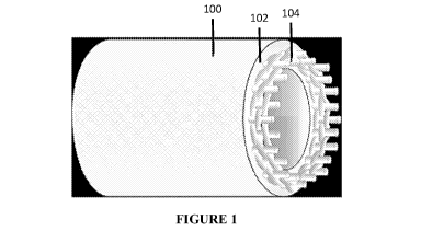
[0046] Figure 1
shows a schematic illustration of the hose 100. Extruded layer 102, such
as TPU, encases an open aramid weave/mesh 104. In this manner, the aramid
weave/mesh is
not deliberately exposed to the ambient environment or the fluid carried
within the hose, and
its primary purpose to deliver sufficient structural strength, including by
way of the pillaring
described herein.
[0047] Figure 2
more specifically illustrates a weave pattern in which the warp strands W
and filler strands F are interwoven so as to leave deliberate gaps in the
resultant fabric sheet.
As a non-limiting example, each warp risers and sinkers traverse two separate
strands of
filler. In turn, two strands of filler yarn are paired together and similarly
traverse two separate
strands of warp. This pattern creates small gaps G, which are enable and allow
for TPU or
other similar extruded resins to deliberately penetrate the sheet and form
pillars as described
above. Other approaches for forming gaps G are also possible (e.g., increasing
the number
threads traversed by the respective risers and sinkers, pairing additional
strands of thread in
the pattern, decreasing the strand diameter, etc.).
[0048] Notably,
and especially in comparison to protective function a woven jacket
provides in other hoses (e.g., fire hoses), the approach of leaving gaps G may
be
counterintuitive. That is, because the weave is intended to protect everything
enclosed by it,
14
CA 03189555 2023-01-16
WO 2022/015373
PCT/US2021/018192
the deliberate provision of small gaps would seem to weaken the weave, whereas
the
inventors determined the pillaring ratios disclosed herein actually provide
the hose with its
improved performance, including enhanced the structural strength by embedding
a structural
support within the extruded/TPU layer(s).
[0049]
Thermoplastic polyurethane is then extruded through this woven aramid mesh. In
particular, a through the weave extrusion process is utilized in which the
jacket runs though
the rubber extrusion head. This approach simultaneously coats the weave on the
inside and
outside with TPU. Alternative extrusion materials may include ethylene
propylene diene
monomer rubber (EPDM), mixtures of EPDM and styrene butadiene rubber (SBR),
polychloroprene (e.g., Neoprene), and other nitrile rubber derivative
compounds, depending
upon the precise nature of the desired performance characteristics.
[0050] The TPU
pillaring network extending through the aramid weave creates a unitary
hose with improved durability that is ideal for the various types of hoses
contemplated herein.
Pressurization of the hose (by fluid flowing therethrough) may further improve
the
enmeshing by urging the TPU 102 into closer contact with the aramid weave 104.
[0051]
Significantly, this pillaring effect can be leveraged in other combinations of
extruded materials and mesh weaves. For example, an alternative extrusion
material could be
paired with a nylon, polyester, and/or aramid warp and fills yarns. As above,
the key trait is
to allow for sufficient gaps to promote the pillaring that sustains the
structural integrity of the
protective, extruded material while simultaneously selecting materials and
weave patterns
that have sufficient tensile strength and compatible diameters for spacing and
gap creation.
[0052] Figures
3 and 4 shows a cross sectional view of an exemplary inventive hose 100
in which the TPU layers 110 can be distinguished from the pillared TPU/weave
layer 120.
This close contact and elimination of inner and outer jackets prevents the
problem of
delamination and bubbling experienced in prior art agricultural or other
hoses.
CA 03189555 2023-01-16
WO 2022/015373
PCT/US2021/018192
[0053] Standard
hose lengths would be 330 feet (-100 m) or 660 feet (-200 m), although
any length in excess of 330 feet (-100 m) and up to 1,320 feet (-400 m) can be
constructed
according to this invention. The preferred diameter would be at least 4.5
inches (-11 cm),
with at least a 2:1 tensile ratio, at least 600-750 PSI (-41.4 ¨ 51.7 bar)
burst pressure ratings,
and/or tensile strengths exceeding 100,000 pounds.
100541 Further,
it will be understood that the necessity for such long lengths of hose is
neither trivial nor easily solved by coupling smaller sections of hoses. In
particular, each
coupling point on a hose represents a potential weak point where leaks could
develop owing
to imperfect seals, incorrect or misaligned coupling, and increased chances
for becoming
entangled, owing to the fact that conventional couplings exceed the diameter
of the hose
itself Additionally, coupling mechanisms add costs that can be avoided by
providing a
single, continuous line of hose.
[0055] Hoses
made according to the constructions and methods contemplated herein
exhibit superior performance characteristics. In addition to possessing the
requisite 2:1 tensile
ratio, these hoses will have diameters of greater than 4 inches (-10
cm)¨including 5, 6, 7, 8,
9, 10, 12, and 16 inch diameters (-10, ¨12.5, ¨15, ¨17.5, ¨20, ¨22.5, ¨25.5,
¨30.5, and ¨40.5
cm)¨that accommodate vastly improved load capabilities. Specifically, loads in
excess of
100,000, 120,000, and even 140,000 pounds are possible. When coupled with the
extended
lengths required by some hose applications, these capabilities form a key
distinguishing
features over existing solutions.
[0056] Further
aspects of the invention may be discerned from careful study of the
features illustrated in the drawings. While structures that are most pertinent
to the operation
of the hose are highlighted above, still further functions and structures will
be appreciated by
skilled persons upon studying the drawings in their entirety, particularly
with respect to
substitution of materials and methods of manufacture.
16
CA 03189555 2023-01-16
WO 2022/015373
PCT/US2021/018192
[0057] In
addition to providing structural integrity and desired length, strength, and
tensile ratios, the materials should also be selected for workability, cost,
and weight. Various
standard testing methods, particularly those established by American National
Standards
Institute (New York, NY), UL (Northbrook, IL), and/or the National Fire
Protection
Association (Quincy, MA), may be useful in characterizing the components
and/or overall
performance of the invention contemplated herein, particularly with respect to
durability of
the hose. ASTM D3389-10 (abrasion), NFPA 1961 (abrasion), and UL 19 "Lined
Fire Hose"
all provide informative metrics.
[0058]
Materials selection is a key aspect of the synergistic effects of the
pillaring
described herein. Therefore, arbitrary or speculative substitutions of the
materials and
methods of making may be impractical, cost prohibitive, and/or otherwise not
amenable to
manufacturing processes and performance expectations inherent to the intended
use/application for the hose. In the foregoing disclosure, it will be
understood that materials
selection, processing techniques, and resultant hoses involve highly
specialized
considerations in which substitutions and changes may not be feasible or
readily apparent to
those skilled in in this field.
[0059] In view
of the foregoing, various disclosed aspects of a single ply, continuous
length (preferably at least 300 feet or more in length) and high strength
(preferably at least a
tensile ratio of at least 2 to 1) comprise and/or consist of any combination
of the following
elements:
= a woven tubular mesh including aramid fibers encased within a
thermoplastic
polymer;
= a woven tubular mesh having or consisting of a warp yarn with a stated
thickness and
a filler yarn with a thickness to produce a height of the woven tubular mesh,
said warp
17
CA 03189555 2023-01-16
WO 2022/015373
PCT/US2021/018192
and filler yarns woven in a pattern to produce a nominal height and a gap area
in the
woven tubular mesh;
= a thermoplastic polymer extruded through the woven tubular mesh to
completely fill
the gap area along the nominal height throughout some or all of the woven
tubular
mesh;
= wherein the hose possesses a tensile ratio of at least 2 to 1;
= wherein the woven tubular mesh and/or warp and filler yarns all/each
consists
essentially of aramid or para-aramid fibers.
= wherein the thermoplastic polymer is thermoplastic polyurethane and/or
thermoplastic
vulcanizate;
= wherein the hose has a continuous length of at least 300 feet and an
inner diameter of
at least 4.5 inches when the hose is in use;
= wherein the continuous length is less than or equal to 1,320 feet and the
inner
diameter is less than or equal to 16 inches;
= wherein the hose has tensile strength greater than 75,000 pounds;
= wherein the hose has tensile strength between 100,000 and 200,000 pounds;
= wherein the thermoplastic polymer is extruded so as to create a
contiguous layer of
the thermoplastic polymer on one or both of inner and outer facings of the
woven
tubular mesh (i.e., the mesh is completely encased);
= wherein the hose has a bending radius of at least 90 degrees without
kinking or
permanently deforming the woven tubular mesh or the thermoplastic polymer; and
= wherein a height-to-area aspect ratio for thermoplastic pillars
penetrating the woven
tubular mesh is less than 35 and preferably between 14 and 32 when a filler
yarn
angle is at 30 or less than 40 and preferably between 16 and 38 when a filler
yarn
angle is at 45 .
18
CA 03189555 2023-01-16
WO 2022/015373
PCT/US2021/018192
[0060]
Furthermore, various methods of making single ply hoses are contemplated as
aspects of the invention. For example, a hose having a tensile ratio (as
defined above) of at
least 2:1 can be achieved by selecting first and second aramid yarns, each of
which has a
discrete and differing thickness. These respective thicknesses are further
selected to ensure
that aspect ratio (height:root area of the gap in the weave) is attained, all
as quantified
above/herein. These yarns are then woven into a tubular mesh, and a
thermoplastic material is
extruded through an inner facing and/or outer facing of the tubular mesh, with
sufficient
thermoplastic material provided to form complete and contiguous layers on the
inner and
outer facings of the tubular mesh. In some aspects, the tubular mesh is woven
to have a
length of between 300 and 1,320 feet, and a nominal diameter of between 4 and
16 inches. In
some aspects, the thermoplastic material is TPU or TPV. Still further
limitations to this
method can be discerned with reference to the foregoing disclosure.
[0061]
Nevertheless, it is also understood that the invention may not to be limited
only to
the embodiments disclosed. Minor alterations to materials and methods are
possible without
departing from the scope of the appended claims or the equivalents thereof, so
long as the
tensile strength, long-length unitary construction, and flexibility
requirements are met. For
example, different grades of TPU or TPV could be selected, weave patterns
could be altered
to promote further pillaring, and/or the length and diameter of the hose all
qualify as minor
alterations.
[0062] The
invention is expected to have immediate and particular utility in the field of
agricultural hoses. "Drag line" agricultural hoses are frequently repositioned
and, therefore,
must be comparatively light weight, flexible, and of a sufficient unitary
length (so as to avoid
the issues of coupling noted above). Further, the exterior surface must be
durable enough to
withstand frictional forces when the hose is dragged over uneven ground, while
the remaining
19
CA 03189555 2023-01-16
WO 2022/015373
PCT/US2021/018192
construction must accommodate high fluid pressure and, in some instances,
abrasive flow
attributed to ice or other solids or particulates.
[0063] Hoses
made according to this disclosure can be employed in still further uses. For
example, agricultural applications also rely on "main line" feed that handles
significantly
larger volumes than the drag lines. Mining applications expose the exterior of
the hose to
even harsher friction-induced environments (e.g., jagged and abrasive
rocks/edges
encountered within a well/bore hole, greater temperature variations including
possible partial
freezing and ice formation on and in the hose, etc.). Marine and military
applications
emphasize the need for high capacity and comparatively light weight. Water and
food
transport applications would also benefit from the tensile strength,
portability, and
comparatively higher capacities (in comparison to existing solutions within
that field). And,
in all of these applications, the flexibility of a hose (in comparison to
rigid tubes or pipes) is
advantageous if not critical.
[0064] As used
herein, flexibility should be understood to mean that the hose can
withstand positioning at extreme bend radii (e.g., being formed into angle
approaching or
often exceeding 900) without kinking or other permanent changes or deformation
to the shape
of the hose itself (i.e., the mesh and/or thermoplastic). In contrast, a wire-
reinforced sleeve or
rigid or semi-rigid tube lacks the resilience of a true hose because the wire
reinforcement will
fail to return to its original shape. In the same manner, the length of rigid
tubing is limited by
practical considerations (e.g., transportation of the tube itself), meaning
that coupling, welds,
or other means of affixing discrete segments of tubes becomes necessary, with
each
connection point representing a potential mode of failure (in short, meaning
that rigid tubes
such as pipes are completely are not analogous to hoses). Yet another
distinctive advantage of
flexible hose in comparison to reinforced or rigid tubes or pipes is the fact
that, when not in
use, a flexible hose is collapsible. In turn, the collapsible and resiliently
bendable nature of
CA 03189555 2023-01-16
WO 2022/015373
PCT/US2021/018192
flexible hoses allows them to be coiled and stored without occupying nearly
the
volume/space required by less or non-flexible alternatives.
21