Note: Descriptions are shown in the official language in which they were submitted.
CA 03190123 2023-01-24
1
System for air conditioning the interior of a building
The invention relates to a system for air conditioning the interior of a
building.
It is known from the general state of the art to take appropriate precautions
in
the change of seasons to keep temperatures in indoor spaces in a temperature
range that is comfortable for the users. Various systems of heating are used
to
increase the temperature, while air-conditioning units are often used to lower
the temperature by feeding cooled outdoor air into the interior via a cooling
io compressor.
Modern systems are used as so-called ventilation and air-conditioning systems,
in which the outside air can be fed into the interior of the building via a
heat ex-
changer by means of a radial fan. Exhaust air is often fed to the heat
exchanger
by means of an evaporative cooler, with the air drawn in by another radial fan
led outside the building as extract air. In addition to various filters for
cleaning
the air, auxiliary heaters can also be used to enable ventilation of the
interior.
An example of such a ventilation system is known from DE 10 2018 213 274
Al, which discloses an air conditioner unit with a device housing 1 with an ex-
haust air opening, air supply opening, exhaust air opening and outside air
open-
ing, an air supply and exhaust air fan, in recirculation mode of an outside
air-
exhaust air flow, and exhaust air-supply air flow in a row, and in outdoor air
op-
eration of the exhaust air-exhaust air flow, and outdoor air-supply air flow
ar-
ranged one above the other cross-flow heat exchangers in the flow paths of the
outside air-supply air flow, and the exhaust air-exhaust air flow arranged
heat
exchanger bypass flaps for transferring thermal energy between the air flows,
a
hybrid refrigeration system with a compressor, an evaporator, and a condenser,
and a water/water-glycol refrigerant heat exchanger as an additional
condenser,
a reheating device, a device for adiabatic spray dampening, flaps for
controlling
Date Recue/Date Received 2023-01-24
CA 03190123 2023-01-24
2
the air flows and a device for regulating the humidity and temperature of at
least
part of the air flows.
Furthermore, it is known to supply outdoor air to an indoor space, whereby all
indoor spaces of a building are connected via a common exhaust air duct,
through which the exhaust air can be supplied to a heat pump, so that the ener-
gy contained in the exhaust air can be transferred as extract air, for example
to
a hot water tank, via the heat pump before leaving the building. Such exhaust
air heat pumps contribute to the energy efficiency of a building.
DE 29 26 610 Al describes a storage device for providing the input heat energy
at a low temperature level for heat pump systems, which absorb this energy and
release it at a higher temperature level. A water basin is designed in such a
way
that its water content can freeze without damaging the basin and that a heat
is exchanger system located at the bottom of the basin or embedded in the
bottom
of the basin allows the cooling and freezing heat of this basin to be fed to
the
cold side of a heat pump.
In addition to the use of an artificial water basin, it is also known to use
natural
bodies of water as a storage medium.
For example, DE 10 2015 104 909 Al describes an energy storage system that
has a heat exchanger floating on a lower basin in the form of a lake that can
preferably be filled with water via a first supply line, whereby water from
the
lower basin can be supplied to a heat pump in separate circuits via a second
supply line and coolant can be supplied to a heat pump in separate circuits
via a
third supply line, so that energy can be extracted via the heat exchanger with
icing of the water of the lower basin or in the form of sensible heat from the
wa-
ter of the lower basin and can be passed on to a consumer for heat dissipation
and/or cold dissipation.
Date Recue/Date Received 2023-01-24
CA 03190123 2023-01-24
3
Furthermore, a floating device for transferring heat energy into a body of
water
and for extracting heat energy from the body of water is known from DE 10
2015 121 177 Al, which has a water heat exchanger which, after the device
has been placed on the body of water, immerses into the water and has an inlet
and an outlet for a heat transfer fluid which can release heat energy to the
body
of water or extract heat energy from the body of water. The device further com-
prises an air heat exchanger through which ambient air can flow, and further
comprises an inlet for water from the body of water and an outlet so that
water
io from the body of water can flow through the air heat exchanger, whereby
heat
energy can be transferred between the ambient air flowing through the air heat
exchanger and the water flowing through the air heat exchanger.
The devices described above usually work together with a heat pump installed
is in a building. This heat pump can, for example, be supplied with
electrical ener-
gy from the power grid or its own power storage.
Against this background, the task now arises to create a system for air-
conditioning of indoor spaces which, compared to hitherto systems, enables
20 year-round use, and has lower installation costs with higher energy
efficiency.
This task is solved by the features of patent claim I. Further advantageous em-
bodiments of the invention are the subject of the respective sub-claims. These
can be combined with each other in a technologically useful manner. The de-
25 scription, particularly in connection with the drawing, additionally
characterises
and specifies the invention.
According to the invention, a system is provided for air-conditioning interior
spaces of a building which are connected by at least one exhaust air duct,
30 wherein one or more interior spaces are provided with an air-
conditioning unit
Date Recue/Date Received 2023-01-24
CA 03190123 2023-01-24
4
which has a supply of outdoor air, which delivers supply air or recirculated
air to
the interior space or spaces, and which is connected to a fluid circuit of a
heat
pump, wherein the exhaust air duct and a further fluid circuit of the heat
pump
are connected to an energy storage device installed outside the building,
where-
in the energy storage device is designed for energy transfer and for energy
storage with a heat exchanger in a liquid reservoir, which is connected via
the
heat exchanger to the fluid circuit of the heat pump, wherein the exhaust air
is
led through a heat exchanger in the liquid reservoir.
io .. According to the invention, in the system for air conditioning of indoor
spaces,
the air conditioner is used for heating and cooling the outdoor air by means
of
the heat pump. Space heaters that are often used in regions in which heating
is
required can be abandoned. The exhaust air from the interior of the building
is
led over the energy storage unit and let out as extract air. A large part of
the
is energy is recovered by the heat pump by the other fluid circuit. In
contrast to the
previously used space heating systems in combination with air-conditioning
units, installation costs are significantly reduced. In regions where heating
is
required, for example, air-conditioning units often have no function in winter
be-
cause underfloor heating is used as room heating for reasons of comfort.
20 Known air-conditioning units also have a connection for the supply of
fresh air,
which, however, is only mixed with the supply air in a predefined ratio in con-
nection with a recirculation mode and which often must be provided preheated
as so-called primary air. Overall, the energy efficiency of the system
according
to the invention for air-conditioning of indoor spaces is higher than that of
sys-
25 tems known from the state of the art, since the energy-intensive air
ventilation is
largely abandoned.
According to one embodiment of the invention, the exhaust air, after leaving
the
heat exchanger in the liquid reservoir, is led as extract air to an air heat
ex-
Date Recue/Date Received 2023-01-24
CA 03190123 2023-01-24
changer that is also connected to the heat pump. In this case, the extract air
can mix with ambient air upstream of the air heat exchanger.
The concept according to the invention is extended to the effect that the ex-
5 haust air, after flowing through the heat exchanger in the liquid
reservoir and
leaving the system, is fed to an air heat exchanger, whereby the exhaust air
can
mix with ambient air before the air heat exchanger. The energy still contained
in
the exhaust air can now also be used by the air heat exchanger, whereby it has
proven advantageous to first feed the exhaust air to a heat exchanger with a
liquid reservoir and not to mix it immediately with the outdoor air, since in
this
way potential large temperature differences can be avoided. The combination of
a first heat exchanger in the liquid reservoir and a second heat exchanger as
an
air heat exchanger in combination with the supply of outdoor air provides for
a
very efficient operation of the system according to the invention.
According to a further embodiment of the invention, the air heat exchanger is
arranged above the liquid reservoir in such a way that a radial, inwardly
directed
air flow of exhaust air and outdoor air can be induced by the air heat
exchanger
by means of a fan arranged in the interior, the air flow leaving the system in
a
.. central area.
Advantageously, the air flow of extract air leaves the liquid reservoir along
the
outer edge of the liquid reservoir, so that a flow through the air heat
exchanger
then advantageously is directed radially inwards again, so that the air flow
can
leave the system in a central area. In this way, an air flow is made possible
that
follows the arrangement of the individual components without major
redirections
around obstacles, so that an overall simple installation of the energy storage
system is possible.
Date Recue/Date Received 2023-01-24
CA 03190123 2023-01-24
6
According to a further embodiment of the invention, an air inlet for outdoor
air is
slot-shaped along the brim of a cover and an air outlet for ambient air and ex-
tract air is preferably designed centrally in the cover.
The flow of outdoor air through the air heat exchanger can be easily achieved
in
this way, so that a compact design of the energy storage device contributes to
reducing the overall installation costs of the system for air conditioning of
indoor
spaces.
According to a further embodiment of the invention, the air conditioning unit
is
installed on a ceiling, on a wall or on a parapet wall in the interior.
Depending on the design of the interior, the cooling unit can be installed at
dif-
ferent locations, whereby different designs of the cooling unit can also be se-
lected, according to the use in a residential building or in an office
building. In
addition to the connections to the heat pump and an outside air supply, a con-
nection to the exhaust air duct must also be created for the cooling unit.
According to a further embodiment of the invention, the air-conditioning unit
is
designed as a floor-standing unit.
In this way, installation is facilitated, particularly in living spaces since
technical
details are no longer visible.
According to a further embodiment of the invention, when heating is required,
the air-conditioning unit heats the outdoor air before it is discharged as
supply
air into the interior by means of the fluid circuit of the heat pump.
The energy stored in the fluid reservoir of the energy storage can heat the
out-
door air with the heat pump by means of the fluid circuit, for a pleasant
indoor
Date Recue/Date Received 2023-01-24
CA 03190123 2023-01-24
7
climate when heating is required. The discharged exhaust air is in turn fed to
the energy storage such that the energy contained therein can be extracted.
According to another embodiment of the invention, when cooling is required,
the
air-conditioning unit cools the outdoor air before it is discharged as supply
air
into the interior by means of the fluid circuit of the heat pump.
In addition to the function of space heating, the system according to the
inven-
tion can also be used for air conditioning of indoor spaces.
According to a further embodiment of the invention, the air conditioner
operates
in recirculation mode.
If neither heating nor cooling of the room air is required, the air-
conditioning unit
is can operate in recirculation mode in order to exchange used room air so
that it
is possible to stay indoors under improved conditions.
In the following, some embodiments are explained in more detail with reference
to the figures. They show:
Figurel shows a schematic side view of a system according to the invention,
Figure 2 shows a sectional view through an energy storage device for use in a
system according to Figure 1,
Figure 3 shows a top view of the energy store from Figure 2, and
Figure 4 shows a schematic representation of an air conditioning unit for use
in a system according to Figure 1.
Date Recue/Date Received 2023-01-24
CA 03190123 2023-01-24
8
In the figures, identical or functionally similar components are given the
same
reference signs.
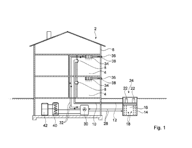
Figure 1 shows an embodiment of a system 2 according to the invention for air-
s conditioning the interior spaces 4 of a building 6. The building 6 may,
for exam-
ple, be a residential building or an office building. However, the invention
can be
applied to different types of buildings, thus the example shown should not be
considered definite. Each of the interior spaces 4 is connected via an exhaust
air opening 8 to an exhaust air duct 10, which removes exhaust air from the in-
tenor spaces 4.
The exhaust air duct 10 is connected via a supply line 12 to an energy storage
device 14, which has a liquid reservoir 16 in a lower part, in which a heat ex-
changer 18 is located. The energy reservoir 14 is located outside the building
6
is and is typically embedded below ground level. Above the liquid reservoir
16, an
air heat exchanger 22 is located above an insulation layer 20.
The air heat exchanger 22 is arranged in several segments around a central
area 24 of the energy reservoir 14. The exhaust air supplied via the supply
line
12 is first passed through a heat exchanger not shown in Figure 1, which is lo-
cated below the insulation layer 20 and is marked with the reference sign 26
in
Figure 1, so that the energy contained in the exhaust air is first supplied to
the
liquid reservoir 16.
.. After passing through the heat exchanger 26, the air is guided radially
from the
outside through the air heat exchanger 22 and leaves the system 2 in the cen-
tral area 24. For the operation of the heat exchanger 18, a fluid circuit 28
is pro-
vided which connects the heat exchanger 18 with a heat pump 30 preferably
arranged inside the building 6. A further fluid circuit 32 connects the heat
pump
30 to an air conditioning unit 34 which, in addition to the connection to the
fur-
Date Recue/Date Received 2023-01-24
CA 03190123 2023-01-24
9
ther fluid circuit 32, has a supply of outdoor air through an opening 36 by
means
of the supply line 38.
Furthermore, the heat pump 30 can also be connected to other components,
such as a hot water tank 40 which is connected to a heating system 42. How-
ever, these components do not form part of the invention, so that a detailed
de-
scription thereof can be dispensed with.
In Figure 2, the energy storage device 14 is shown in a cross-sectional view.
The energy storage device 14 has multiple pipes in the fluid reservoir 16
which
are connected to the heat pump 30 via the fluid circuit 28. Typically, the
fluid
reservoir 16 will be filled with water or a paraffin solution. Above the fluid
is the
heat exchanger 26, through which the exhaust air of the building 6 flows
radially
outwards, so that the exhaust air leaves as extract air 44 through a slot
between
the insulation layer 20 and an outer shell 46. A fan 48 in the central area
24,
which draws the extract air 44 together with outdoor air 50, which can flow in
radially from outside between the sleeve 26 and a cover 52, in the direction
of
the central area 24, where the air then leaves the system 2.
The air heat exchanger 22 is above the liquid reservoir 16 above the
insulation
layer 20. The exhaust air supplied via the supply line 12 is first passed over
the
heat exchanger 26 so that the energy contained in the exhaust air is first
trans-
ferred to the liquid reservoir 16. After passing through the heat exchanger
26,
the air is led radially from the outside through the air heat exchanger 22 and
leaves the system 2 in the central area 24. For the operation of the heat ex-
changer 18, in addition to the fluid circuit 28, which connects the heat
exchang-
er 18 to a heat pump 30 preferably installed inside the building 6, a further
fluid
circuit not shown in the figures is provided, which connects the air heat ex-
changer 22 to the heat pump 30 installed inside the building 6.
Date Recue/Date Received 2023-01-24
CA 03190123 2023-01-24
With reference to Figure 3, the distribution of the exhaust air from the
building 6
is shown in more detail. The exhaust air is fed to the heat exchanger 26 at
one
point, so that after passing through the heat exchanger 26 it leaves it
radially
outwards. The heat exchanger 26 can be made of metal with multiple, particu-
5 larly radially aligned fins, which direct the air flow as shown in Figure
3.
With reference to Figure 4, a schematic view of the air conditioning unit 34
is
shown. In addition to supplying the outdoor air via the supply line 38, air
can
also be supplied via an inlet opening 60 and a connecting piece 62 via a fan
64
10 to a cooling or heating device 66 which is connected to the fluid
circuit 32. Sub-
sequently, the air thus tempered leaves the air-conditioning unit 34 through
an
outlet opening 68. Additional components, such as a bypass line for bypassing
the cooling or heating device 66 in recirculation mode, can of course be added
within the scope of expert knowledge.
In the system 2 for air-conditioning the interior spaces 4, the air-
conditioning
unit 34 is used for heating and cooling the outdoor air by means of the heat
pump 30. The space heaters that are often present in regions where heating is
required can be abandoned. The exhaust air from the interior rooms 4 of the
building 6 is led over the energy storage 14 and blown out as extract air. A
large
part of the energy is thereby recovered by the heat pump 30 via the fluid
circuit
28.
The features as described above, and in the claims, as well as those shown in
the figures, can be advantageously implemented both individually and in
various
combinations. The invention is not limited to the described embodiments but
can be modified in various ways within the scope of skilled craftsmanship.
List of reference numbers
Date Recue/Date Received 2023-01-24
CA 03190123 2023-01-24
11
2 system
4 interior spaces
6 building
8 exhaust air opening
10 exhaust air duct
12 supply line
14 energy store
16 liquid reservoir
18 heat exchanger
to 20 insulation layer
22 air heat exchanger
24 central area
26 heat exchanger
28 another fluid circuit
30 heat pump
32 fluid circuit
34 air conditioning unit
36 opening
38 inlet line
40 hot water tank
42 heating system
44 extract air
46 outer shell
48 fan
50 outdoor air opening
52 cover
60 inlet opening
62 connecting piece
64 fan
66 cooling or heating device
Date Recue/Date Received 2023-01-24
CA 03190123 2023-01-24
12
68 outlet opening
Date Recue/Date Received 2023-01-24