Note: Descriptions are shown in the official language in which they were submitted.
CA 03190135 2023-01-24
WO 2022/038265 PCT/EP2021/073144
PROCESS FOR HYDROTREATMENT OF
MATERIALS FROM RENEWABLE SOURCES
FIELD OF THE INVENTION
[0001] The present invention relates to a process for the hydrotreatment of
a feedstock
comprising materials from renewable sources, useful for the production of
fuels, fuel
components and/or chemical feedstocks.
BACKGROUND OF THE INVENTION
[0002] The increased demand for energy resulting from worldwide economic
growth
and development have contributed to an increase in concentration of greenhouse
gases in the
atmosphere. This has been regarded as one of the most important challenges
facing mankind
in the 21st century. To mitigate the effects of greenhouse gases, efforts have
been made to
reduce the global carbon footprint. The capacity of the earth's system to
absorb greenhouse
gas emissions is already exhausted. Accordingly, there is a target to reach
net-zero emissions
by 2050. To realize these reductions, the world is transitioning away from
solely
conventional carbon-based fossil fuel energy carriers. A timely implementation
of the energy
transition requires multiple approaches in parallel, including for example,
energy
conservation, improvements in energy efficiency, electrification, and efforts
to use
renewable resources for the production of fuels and fuel components and/or
chemical
feedstocks.
[0003] Vegetable oils, oils obtained from algae, and animal fats are seen
as renewable
resources. Also, deconstructed materials, such as pyrolyzed recyclable
materials or wood,
are seen as potential resources.
[0004] Renewable materials may comprise materials such as triglycerides
with very
high molecular mass and high viscosity, which means that using them directly
or as a mixture
in fuel bases is problematic for modern engines. On the other hand, the
hydrocarbon chains
that constitute, for example, triglycerides are essentially linear and their
length (in terms of
number of carbon atoms) is compatible with the hydrocarbons used in/as fuels.
Thus, it is
attractive to transform triglyceride comprising feeds in order to obtain good
quality fuel
components. As well, renewable feedstocks may comprise unsaturated compounds
and/or
oxygenates that are unsaturated compounds.
1
CA 03190135 2023-01-24
WO 2022/038265 PCT/EP2021/073144
[0005] The
renewable feedstocks, whether processed alone or coprocessed with
petroleum-derived feedstocks, are therefore hydrotreated to remove
contaminants such as,
but not limited to, oxygen, sulphur, and nitrogen.
[0006]
Examples of such processes are available. For example, Craig et al. (US
4,992,605, 12 Feb 1991) disclose a process for producing hydrocarbon products
in the diesel
boiling range, mainly C15-C18 straight chain paraffins, the process comprising
hydroprocessing vegetable oils or some fatty acids at conditions effective to
cause
hydrogenation, hydrotreating and hydrocracking of the feedstock (temperature
350-450 C;
pressure 4.8-15.2 MPa; liquid hourly space velocity 0.5-5.0 hr-1) using a
commercially
available hydroprocessing catalyst.
Cobalt-molybdenum and nickel-molybdenum
hydroprocessing catalysts are mentioned as suitable catalysts.
[0007]
Monnier et al. (US 5,705,722, 6 Jan 1998) relates to a process for producing
liquid hydrocarbons boiling in the diesel fuel range from a biomass feedstock
comprising
tall oil with a relatively high content of unsaturated compounds. The
feedstock is
hydroprocessed at a temperature of at least 350 C.
[0008] More
recently, there has been an appreciation that hydrogenation of unsaturated
compounds, such as olefins, diolefins, and aromatics, is highly exothermic.
Hydrodeoxygenation is also an exothermic reaction. Renewable feedstocks with a
high
content of unsaturated compounds will generate a significant heat release upon
complete
hydrogenation of all unsaturated compounds. The high exothermicity will result
in a large
temperature increase over the catalyst beds in the reactor, if no measures are
taken.
[0009]
Currently, the high exothermicity in hydroprocessing of renewable materials is
generally dealt with by application of a high liquid recycle rate to the
reactor inlet in
combination with a significant amount of liquid quench. The recycle and/or
quench streams
are used to dilute the reactivity of the fresh feed and provide a heat sink
for the exothermic
reaction.
[00010] For
example, Myllyoja et al. (U58,859,832B2, 14 Oct 2014) describes a process
for the manufacture of diesel range hydrocarbons wherein a feed is
hydrotreated in a
hydrotreating step and isomerized in an isomerization step. The feed,
comprising fresh feed
containing more than 5 wt.% of free fatty acids and at least one diluting
agent, is hydrotreated
at a reaction temperature of 200-400 C, in a hydrotreating reactor in the
presence of catalyst,
and the ratio of the diluting agent/fresh feed is 5-30:1. The diluting agent
is needed,
according to Myllyoj a et al., to reduce undesired side reactions, improve
reaction selectivity,
2
CA 03190135 2023-01-24
WO 2022/038265 PCT/EP2021/073144
limit temperature increases in the catalysts beds, avoid harmful and partially
converted
intermediate products, and extend catalyst life considerably.
[00011] As another example, Marker et al. (US7,982,076B2, 19 Jul 2011),
describes a
process for producing diesel boiling range fuel from renewable feedstocks such
as plant oils,
animal fats and oils, and greases which involves treating a renewable
feedstock by
hydrogenating and deoxygenating to provide a diesel boiling range fuel
hydrocarbon
product. In the process of Marker et al., a portion of the hydrocarbon product
is recycled to
the treatment zone to increase the hydrogen solubility of the reaction
mixture. The volume
ratio of recycle to feedstock is in the range of about 2:1 to about 8:1.
Simulations show that
the hydrogen solubility increases rapidly until a recycle ratio of 2:1. From
recycle to feed
ratios of 2:1 to 6:1, the simulation showed that hydrogen solubility remained
high.
According to Marker et al., one benefit of the hydrocarbon recycle is to
control the
temperature rise across the individual beds. Reportedly, without recycling,
after some time,
the level of oxygen in the product started to continuously increase indicating
the catalyst had
significantly deactivated and triglycerides were no longer sufficiently
reacted.
[00012] However, using product for recycle and/or quench adds to the total
hydraulic load
of the system, to the energy consumption and to increased size of equipment.
Further, it should
be noted that if gas would be used as quench, the amount of gas that would be
required to
quench the exothermicity would be very large. Generally, these conventional
solutions
adversely affect the cost effectiveness and energy efficiency of the
operation.
[00013] Toppinen et al. (W02020/165496A1, 20 Aug 2020) describes a fluid
mixer
having a cylindrical mixing chamber, a first fluid inlet for conducting
effluent from the first
catalyst bed to the mixing chamber to produce a spiral stream in the mixing
chamber and a
second fluid inlet for conducting a quench fluid tangentially into the spiral
stream. An outlet
channel is concentric to the mixing chamber and directs mixed fluids downward
at a central
location. The outlet channel is used to produce turbulence in the stream of
bed effluent and
quench fluids to reduce local concentration maxima in the mixture, thereby
reducing
corrosion risk of material surfaces that are in contact with the mixture of
the fluids coming
out from the fluid mixer.
[00014] Himelfarb et al. (U52008/0004476A1, 3 Jan 2008) discloses a process
for
hydrogenation of aromatics in a hydrocarbon feedstock containing a thiopheneic
compound.
A fluid distribution means including a horizontal tray with a plurality of
openings for the
downflow of the feedstock onto the top surface area of the nickel-based
catalyst bed. The
3
CA 03190135 2023-01-24
WO 2022/038265 PCT/EP2021/073144
fluid distribution means reduces hot spots and hot regions within the catalyst
bed resulting
in a higher conversion of the thiopheneic compound. Optionally, a portion of
the liquid phase
product may be recycled to provide an improved overall aromatics conversion
and/or to
control start-of-run temperature.
[00015] Chapus et al. (US2012/0059209A1, 8 Mar 2012) recognizes problems
associated
with high recycle ratios, including high pressure drop, high linear velocity,
high hydraulic
load, and larger reactor volume. To address the problem, Chapus et al. divided
the raw
material stream into a number of different partial stream Fl to Fn identical
to the number of
catalyst beds n in the reactor system. A stream of hydrogen is also divided
into the same
number of partial streams H1 to Hn. When n is greater than 2, each partial
stream of raw
material feed is much larger than the preceding one. Temperature at the
reactor inlet at the
first catalyst bed is adjusted by adding diluting agent only to the streams Fl
and Hi. A
challenge with this solution is that controlling exothermicity is more
complicated with a
divided feed, while catalyst is underutilized with feed bypassing catalyst
beds.
[00016] There remains a need for improving the cost effectiveness and
energy efficiency
of hydroprocessing processes, preferably with improved yields. Specifically,
there remains
a need to avoid the operating and capital costs associated with recycling high
volumes of
reaction product, while addressing the problem of a highly exothermic reaction
of renewable
feedstocks.
SUMMARY OF THE INVENTION
[00017] According to one aspect of the present invention, there is provided
a process for
hydroprocessing a renewable feedstock comprising the steps of introducing the
renewable
feedstock and hydrogen in a downward flow into a top portion of a fixed-bed
reactor;
distributing the downward flow to a top surface of a first catalyst bed in a
manner such that
the top surface is uniformly wetted across the reactor cross section; allowing
the renewable
feedstock to flow downwardly through the first catalyst bed; reacting the
renewable
feedstock in the catalyst bed under hydroprocessing conditions sufficient to
cause a reaction
selected from the group consisting of hydrogenation, hydrodeoxygenation,
hydrodenitrogenation, hydrodesulphurization, hydrodemetallization,
hydrocracking,
hydroisomerization, and combinations thereof to produce a hydrocarbon
effluent; separating
a hydrocarbon liquid stream from the hydrocarbon effluent; and recycling the
hydrocarbon
4
CA 03190135 2023-01-24
WO 2022/038265 PCT/EP2021/073144
liquid for the renewable feedstock in a ratio of 0.4:1 to 1.8:1, based on the
volume of the
renewable feedstock.
BRIEF DESCRIPTION OF THE DRAWING
[00018] The process of the present invention will be better understood by
referring to the
following detailed description of preferred embodiments and the drawings
referenced
therein, in which:
[00019] Figs. 1A-1E are schematic simulations of prior art distribution of
downward
flow;
[00020] Figs. 2A ¨ 2E are schematic simulations of distribution of downward
flow in
accordance with one embodiment of the present invention; and
[00021] Fig. 3 is a schematic representation of one embodiment of a reactor
for use in
the process according to the invention.
DETAILED DESCRIPTION OF THE INVENTION
[00022] The present invention provides a process for hydroprocessing a
renewable
feedstock in a fixed-bed reactor. In accordance with the present invention,
capital and
operating costs can be reduced for a given product yield. Reduced operating
costs translates
to improved energy efficiency and a lower carbon footprint. Furthermore, the
process of the
present invention has improved flexibility for managing a wider range of
renewable
feedstocks that have different saturation levels and/or different oxygen
levels, which, in turn,
have wide variation in reaction exothermicity.
[00023] In accordance with the present invention, the need for recycle can
be reduced
compared to conventional techniques. According to the present invention,
recycle is in a
range of 0.4 to 1.8 times the fresh feed on a volume basis. By providing a
process scheme
capable of operating over the range of 0.4:1 to 1.8:1 recycle, the process has
the flexibility
to adapt to changes in renewable feedstock due to supply, markets, season,
quality, and the
like. For example, a soybean oil feedstock generally has a considerably higher
degree of
unsaturation than a palm oil feedstock. The resulting spread in exothermicity
can result in
needing, for example, two times the amount of recycle for one feed compared to
another.
Having a process that is capable of operating in a recycle range of 0.4 to 1.8
times the feed
provides flexibility when changes in feedstock are required.
[00024] While the examples presented herein demonstrate that unexpectedly
good results
were also shown for 0 recycle, the recycle ratio for the process of the
present invention is in
CA 03190135 2023-01-24
WO 2022/038265 PCT/EP2021/073144
the range of 0.4 to 1.8 times the fresh feed on a volume basis to provide
flexibility due to
changes in feedstock variability. Without recycle, adjustments would be
provided by adding
more catalyst beds for a highly unsaturated renewable feedstock or removing
catalyst beds
for a highly saturated renewable feedstock. This solution is, however, not
very flexible or
practical because the modifications would require significant down-time and a
significant
loss in production.
[00025] Contrary to conventional wisdom of large recycle ratios and divided
feed
streams, the process of the present invention addresses the problem of highly
exothermic
reactions by uniformly wetting a top surface of the catalyst beds in a fixed
bed reactor.
[00026] By "uniformly wetted," we mean that at least 90%, preferably 95%,
most
preferably 100%, of the top surface of the catalyst bed is contacted by the
downflow at a
liquid velocity having a distribution range between highest and lowest local
liquid velocities
of at most 10 %. Measuring liquid velocities is commonly known in the art.
[00027] Uniform wetting of the catalyst surface reduces the occurrence of
localized hot
spots. This improves process efficiency, reduces reactor and catalyst costs,
and improves
safety. The process of the present invention is important for the energy
transition and can
improve the environment by producing low carbon energy and/or chemicals from
renewable
sources, and, in particular, from degradable waste sources, whilst improving
energy
efficiency of the process. By uniform wetting, the catalyst beds can be
operated at a higher
AT and also the AT over the reactor will be higher, thereby reducing the
volume of recycle
and, optionally, quench and recycle needed, as compared to conventional
processes.
[00028] For a given feedstock, throughput and desired reaction severity, as
compared to
a conventional process, the present invention allows for reduced operating
temperature,
reduced WABT (weighted average bed temperature), and/or increased LHSV (liquid
hourly
space velocity) to reach the same conversion.
[00029] Improved wetting may be accomplished by a modification to a
conventional
distribution tray by increasing the density of the nozzles, in the
distribution tray, changing
the downward flow pattern from the nozzles, and combinations thereof.
[00030] In a preferred embodiment, a downward flow of renewable feedstock
is directed
to a distribution tray having a plurality of nozzles. The downward flow of
liquid and gas is
distributed through the plurality of nozzles to a catalyst bed in a manner
such that the area
contacted by the downward flow from each of the plurality of nozzles overlaps
the area
6
CA 03190135 2023-01-24
WO 2022/038265 PCT/EP2021/073144
contacted by the downward flow from at least another of the plurality of
nozzles. In this
way, a top surface of the catalyst bed is uniformly wetted across the reactor
cross section.
[00031] The advantages of the present invention over conventional processes
are
illustrated by first reviewing Figs. 1A-1E. In one embodiment of a
conventional process,
downward flow is directed to a vapor/liquid distribution tray 1 having a
plurality of holes 2
across the cross-section of the tray 1. The distribution tray 1 is typically a
chimney type or
a bubble cap type distribution tray to distribute liquid entering the reactor
via its inlet pipe
or device, on top of the catalyst bed below.
[00032] In Fig. 1A, the distribution tray 1 has a bubble cap 3 associated
with each
opening 2 in the distribution tray 1. Fig. 1B is a depiction of a pattern of
openings 2 in a
distribution tray 1 that has been simplified for ease of illustration to show
a smaller number
of openings 2 with a larger relative diameter compared to the tray diameter.
It will be
understood by those skilled in the art that a conventional distribution tray
will have a larger
number of openings 2, and each will have a smaller diameter relative to the
tray diameter.
Instead of the bubble cap 3, the distribution tray may be provided with
nozzles, other bubble
caps, or other type of opening in the tray.
[00033] The liquid flows downwardly through the bubble caps 3 to a top
surface 4 of the
catalyst bed. The downflow 5 from each nozzle wets the top surface 4 in a
pattern, simulated
in Fig. 1C, that is most likely a mirror-image of the pattern of the tray
openings 2. The
wetted area 6 is substantially the same as the cross-sectional area of the
combined openings.
It will be understood that a portion of the top surface of the catalyst bed
may become wet by
reactor humidity, splashing, or misting of the downward flow. However, this
type of wetting
tends to be superficial, not having the pressure to wet the complete catalyst
volume below,
and is, therefore, outside the definition of uniform wetting of the present
invention.
[00034] By wetting the top surface of the catalyst bed in a limited
pattern, a significant
portion of the top surface, and subsequently the volume of catalyst below, is
not wetted by
the downflow. For example, distribution trays with conventional chimneys wet
about 15%
of the top surface of the catalyst bed, while distribution trays with
conventional bubble caps
wet about 30% of the top surface of the catalyst bed. Fig. 1D illustrates the
consequential
maldistribution of the downflow through the catalyst bed from the wetted area
6 at the top
surface 4 of the catalyst bed. In this depiction, the catalyst is nonuniformly
wetted through
approximately 50% of the height Hc of the catalyst bed. The liquid velocity of
the downflow
through the catalyst bed was calculated and the results are presented in the
simulation in Fig.
7
CA 03190135 2023-01-24
WO 2022/038265 PCT/EP2021/073144
1E. The peaks in Fig. 1E show that the liquid velocity at the top surface of
the catalyst bed
to be in a range of 10-12. Thereafter, the liquid velocity slows as
distribution gradually
increases through the catalyst bed.
[00035] Figs. 1D and 1E illustrate that, in conventional processes,
dispersion of the
feedstock is slow and ineffective. This can lead to underutilized catalyst
and/or bed-grading
material, thermal maldistribution, poor performance, shorter catalyst cycle
length, higher
energy consumption and/or localized hot spots.
[00036] Figs. 2A ¨ 2E illustrate advantages of the process of the present
invention 10 in
comparison to Prior Art Figs. 1A ¨ 1E.
[00037] In Fig. 2A, a distribution tray 12 has openings 14 to allow for
flow of fluid. The
fluid includes the renewable feedstock and hydrogen. The fluid will also
include recycled
hydrocarbon liquid from the reaction product. Optionally, the fluid also
comprises any
petroleum-derived hydrocarbons when coprocessing. Fig. 2B is a depiction of a
pattern of
openings 14 in the distribution tray 12. The distribution tray 12 is provided
with nozzles 16
at the openings 14 in the tray 12.
[00038] The fluid flows downwardly through the nozzles 16 to a top surface
18 of the
catalyst bed. The downflow 22 from each nozzle 16 wets the top surface 18 in a
pattern,
simulated in Fig. 2C, that is an enlarged image of the pattern of the tray
openings 14. The
wetted area 24 is significantly larger than the cross-sectional area of the
combined openings
14. The top surface 18 of the catalyst is therefore uniformly wetted.
[00039] By uniformly wetting the top surface 18 of the catalyst bed,
problems associated
with maldistribution, as depicted in Figs. 1A ¨ 1E are avoided. Fig. 2D
illustrates the
consequential improvement of the downflow through the catalyst bed from the
wetted area
24 at the top surface 18 of the catalyst bed. By uniformly wetting the top
surface 18 of the
catalyst bed, the catalyst is uniformly wetted throughout the bed. In a
comparison of Figs.
1D and 2D, it can be seen that the fully wetted portion of the catalyst bed in
accordance with
the present invention 10, Hi, is approximately 100% of the height of the
catalyst bed whilst
it equals about 50 % of Hc in the prior art depicted in Fig. 1D.
[00040] The fluid velocity of the downflow through the catalyst bed was
calculated and
the results are presented in the simulation in Fig. 2E. By comparing the
results for
conventional processes in Fig. 1E, it can be seen from the simulation in Fig.
2E that the fluid
velocity for the process of the present invention is substantially uniform at
a velocity in a
range of 0.1 ¨ 0.3, with 100% wetting of the top surface, compared to
conventional
8
CA 03190135 2023-01-24
WO 2022/038265 PCT/EP2021/073144
technologies that wet approximately 5% of the surface with a difference
between maximum
and minimum of 0 -11.
[00041] Comparing Figs. 2D and 2E with Figs. 1D and 1E, respectively, shows
the
impact of uniformly wetting the top surface of the catalyst bed in accordance
with the process
of the present invention. The present invention allows for better dispersion
of the feedstock
to improve contact with catalyst and/or bed-grading material, improved thermal
distribution,
improved performance, reduced energy consumption, longer catalysts cycle
length, and/or
reduction in localized hot spots.
[00042] An example of a commercially available distribution tray useful for
an
embodiment of the invention is a high-dispersion distributor tray available
from Shell
Catalysts and Technologies. Muller (U57,506,861, 24 Mar 2009) has a perforated
plate at
the base of a nozzle, while Koros et al. (U55,403,561, 4 Apr 1995) illustrates
a spray
generating device. Modifications like these, in a sufficient density, when
appreciating the
importance of uniformly wetting to produce downflow at a liquid velocity
having a
distribution range between highest and lowest local liquid velocities of at
most 10 %, may
be used in the present invention.
[00043] As used herein, the terms "renewable feedstock", "renewable feed",
and
"material from renewable sources" mean a feedstock from a renewable source. A
renewable
source may be animal, vegetable, microbial, and/or bio-derived or mineral-
derived waste
materials suitable for the production of fuels, fuel components and/or
chemical feedstocks.
[00044] A preferred class of renewable materials are bio-renewable fats and
oils
comprising triglycerides, diglycerides, monoglycerides and free fatty acids or
fatty acid
esters derived from bio-renewable fats and oils. Examples of such fatty acid
esters include,
but are not limited to, fatty acid methyl esters, fatty acid ethyl esters. The
bio-renewable fats
and oils include both edible and non-edible fats and oils. Examples of these
bio-renewable
fats and oils include, but are not limited to, algal oil, brown grease, canola
oil, carinata oil,
castor oil, coconut oil, colza oil, corn oil, cottonseed oil, fish oil,
hempseed oil, jatropha oil,
lard, linseed oil, milk fats, mustard oil, olive oil, palm oil, peanut oil,
rapeseed oil, sewage
sludge, soy oils, soybean oil, sunflower oil, tall oil, tallow, used cooking
oil, yellow grease,
and combinations thereof.
[00045] Another preferred class of renewable materials are liquids derived
from biomass
and waste liquefaction processes. Examples of such liquefaction processes
include, but are
not limited to, (hydro)pyrolysis, hydrothermal liquefaction, plastics
liquefaction, and
9
CA 03190135 2023-01-24
WO 2022/038265 PCT/EP2021/073144
combinations thereof. Renewable materials derived from biomass and waste
liquefaction
processes may be used alone or in combination with bio-renewable fats and
oils.
[00046] The
renewable materials to be used as feedstock in the process of the present
invention may contain impurities. Examples of such impurities include, but are
not limited
to, solids, iron, chloride, phosphorus, alkali metals, alkaline-earth metals,
polyethylene and
unsaponifiable compounds. If required, these impurities can be removed from
the renewable
feedstock before being introduced to the process of the present invention.
Methods to remove
these impurities are known to the person skilled in the art.
[00047] The
process of the present invention is most particularly advantageous in the
processing of feed streams comprising substantially 100% renewable feedstocks.
However,
in one embodiment of the present invention, renewable feedstock may be co-
processed with
petroleum-derived hydrocarbons.
Petroleum-derived hydrocarbons include, without
limitation, all fractions from petroleum crude oil, natural gas condensate,
tar sands, shale oil,
synthetic crude, and combinations thereof. The present invention is more
particularly
advantageous for a combined renewable and petroleum-derived feedstock
comprising a
renewable feed content of at least from 30 wt.%.
[00048] In a hydroprocessing process, renewable feedstock is reacted under
hydroprocessing conditions sufficient to cause a reaction selected from
hydrogenation,
hydrotreating (including, without limitation, hydrodeoxygenation,
hydrodenitrogenation,
hydrodesulphurization, and hydrodemetallization), hydrocracking, selective
cracking,
hydroisomerization, and combinations thereof. The hydroprocessing process may
be a
single-stage or multi-stage and may be conducted in a single reactor or
multiple reactors.
The process of the present invention is a fixed-bed process, wherein a single
reactor or
multiple reactors may independently have a single catalyst bed or multiple
catalyst beds.
The process is operated in a co-current flow of liquid and gas.
[00049] The
process according to the present disclosure is suitable for the production of
fuels and/or fuel components and/or chemical feedstocks, which products
include, for
example, without limitation, naphtha boiling point range products, kerosene
boiling point
range products, diesel boiling point range products, LPG, detergent
feedstocks, feedstocks
for ethylene crackers, and combinations thereof.
[00050] The
hydroprocessing of certain renewable materials is particularly highly
exothermic, for example, without limitation, when the materials comprise high
CA 03190135 2023-01-24
WO 2022/038265 PCT/EP2021/073144
concentrations of unsaturated molecules and/or oxygenates, which results in
large
temperature increases over the catalyst beds.
[00051] A downward flow of renewable feedstock includes fresh feed,
comprising
material from renewable sources, liquid recycle, and, optionally, petroleum-
derived
feedstock in a coprocessing scenario, hydrogen, and, optionally, H2S and/or a
compound for
generating H2S in situ. Hydrogen may be combined with the renewable feedstock
before it
is introduced the hydroprocessing reactor, co-fed with the renewable feedstock
or added to
the hydroprocessing reactor independently of the renewable feedstock. Hydrogen
may be
fresh and/or recycled from another unit in the process and/or produced in a
HMU (not
shown). In another embodiment, the hydrogen may be produced in-situ in the
reactor or
process, for example, without limitation, by water electrolysis. The water
electrolysis
process may be powered by renewable energy (such as solar photovoltaic, wind
or
hydroelectric power) to generate green hydrogen, nuclear energy or by non-
renewable power
from other sources (grey hydrogen).
[00052] Operating conditions in the fixed-bed reactor include pressures in
a range of
from 1.0 MPa to 20 MPa, temperatures in a range of from 200 to 410 C and
liquid hourly
space velocities in a range of from 0.3 m3/m3.h ¨5 m3/m3.h based on fresh
feed. The ratio
of hydrogen to feed supplied in the fixed-bed reactor is in a range of from
200 to 10,000
normal L (at standard conditions of 0 C and 1 atm (0.101A/Pa)) per kg of feed.
Reference
herein to feed is the total of fresh feedstock excluding any recycle that is
added.
[00053] The catalyst may be the same or different throughout the
hydroprocessing
reactor(s) and/or throughout a single catalyst bed or multiple catalyst beds.
Optionally, there
is a mixture of catalysts, or different catalysts may be provided in two or
more layers in a
catalyst bed. In an embodiment of multiple catalyst beds, the catalyst may be
same or
different for each catalyst bed.
[00054] The hydrogenation components may be used in bulk metal form or the
metals
may be supported on a carrier. Suitable carriers include refractory oxides,
molecular sieves,
and combinations thereof. Examples of suitable refractory oxides include,
without
limitation, alumina, amorphous silica-alumina, titania, silica, and
combinations thereof
Examples of suitable molecular sieves include, without limitation, zeolite Y,
zeolite beta,
ZSM-5, ZSM-12, ZSM-22, ZSM-23, ZSM-48, SAPO-11, SAPO-41, ferrierite, and
combinations thereof.
11
CA 03190135 2023-01-24
WO 2022/038265 PCT/EP2021/073144
[00055] The hydroprocessing catalyst may be any catalyst known in the art
that is suitable
for hydroprocessing. Catalyst metals are often in an oxide state when charged
to a reactor
and preferably activated by reducing or sulphiding the metal oxide.
Preferably, the
hydroprocessing catalyst comprises catalytically active metals of Group VIII
and/or Group
VIB, including, without limitation, Pd, Pt, Ni, Co, Mo, W, and combinations
thereof
Hydroprocessing catalysts are generally more active in a sulphided form as
compared to an
oxide form of the catalyst. A sulphiding procedure is used to transform the
catalyst from a
calcined oxide state to an active sulphided state. Catalyst may be pre-
sulphided or sulphided
in situ. Because renewable feedstocks generally have a low sulphur content, a
sulphiding
agent is often added to the feed to maintain the catalyst in a sulphided form.
[00056] Preferably, the hydrotreating catalyst comprises sulphided
catalytically active
metals. Examples of suitable catalytically active metals include, without
limitation,
sulphided nickel, sulphided cobalt, sulphided molybdenum, sulphided tungsten,
sulphided
CoMo, sulphided NiMo, sulphided MoW, sulphided NiW, and combinations thereof.
A
catalyst bed/zone may have a mixture of two types of catalysts and/or
successive beds/zones,
including stacked beds, and may have the same or different catalysts and/or
catalyst
mixtures. In case of such sulphided hydrotreating catalyst, a sulphur source
will typically
be supplied to the catalyst to keep the catalyst in sulphided form during the
hydroprocessing
step.
[00057] The hydrotreating catalyst may be sulphided in-situ or ex-situ. In-
situ sulphiding
may be achieved by supplying a sulphur source, usually H2S or an H2S precursor
(i.e., a
compound that easily decomposes into H2S such as, for example, dimethyl
disulphide, di-
tert-nonyl polysulphide or di-tert-butyl polysulphide) to the hydroprocessing
catalyst during
operation of the process. The sulphur source may be supplied with the feed,
the hydrogen
stream, or separately. An alternative suitable sulphur source is a sulphur-
comprising
hydrocarbon stream boiling in the diesel or kerosene boiling range that is co-
fed with the
feedstock. In addition, added sulphur compounds in feed facilitate the control
of catalyst
stability and may reduce hydrogen consumption.
[00058] In one embodiment of the present invention, the effluent from a
catalyst bed is
quenched before being contacted with a subsequent catalyst bed. After
quenching, the
downflow is directed through a distribution tray provided between two catalyst
beds.
Preferably, the quenched effluent is distributed through the plurality of
nozzles to a second
catalyst bed in a manner such that the area contacted by the downward flow
from each of
12
CA 03190135 2023-01-24
WO 2022/038265 PCT/EP2021/073144
the plurality of nozzles overlaps the area contacted by the downward flow from
at least
another of the plurality of nozzles. In this way, a top surface of the second
catalyst bed is
uniformly wetted across the reactor cross section. Preferably, the type of
distribution tray
used for distributing the downward flow of feedstock to the first catalyst bed
is the same
type of tray as the distribution tray used between catalyst beds.
[00059] Effluent from a catalyst bed can be quenched using a method
described in
IPCOM000266022D ("Process for hydrotreatment of materials from renewable
sources",
ip.com). For example, the effluent may be quenched using an internal heat
exchanger below
the preceding catalyst bed. In another embodiment, the effluent is quenched by
passing at
least a portion of the effluent through an external heat exchanger. The
effluent may be first
separated in a gas/liquid separator before being cooled in the external heat
exchanger.
[00060] Quenching may be accomplished by adding a quench gas (e.g., cooled
recycle
gas) or a quench liquid (e.g., cooled catalyst bed effluent, cooled reactor
effluent, cooled
product stream) to effluent from a preceding catalyst bed before it passes
through an interbed
distribution tray. For example, the quench gas and/or quench liquid may be
added via a
quench mixing device. An example of a quench mixing device is an Ultra-Flat
Quench
System Internals, available from Shell Catalysts & Technologies. Such a quench
mixing
device provides a homogeneous quenched effluent that reduces radial
temperature
differences over the cross section of the reactor and catalyst bed. The
temperature drop
caused by the quenching results in a uniform temperature distribution of the
effluent before
it enters the next catalyst bed. This preferably means that after quenching,
the difference
between the highest and lowest temperature of the quenched effluent over the
reactor cross
section is at maximum 25% of the average temperature drop caused by the
quenching. For
the avoidance of doubt, any quench used between catalyst beds is not the same
as recycling,
as discussed above.
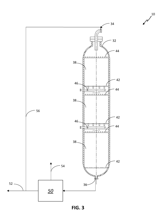
[00061] Referring now to Fig. 3, one embodiment of a fixed bed reactor 32
for use in the
process of the present invention 10 has an inlet 34 and an outlet 36. As noted
above, the
fixed bed reactor 32 of the present invention may have a single catalyst bed
or multiple
catalyst beds. In the embodiment of Fig. 3, there are three catalyst beds 38,
each placed on
a catalyst support grid 42. A distribution tray 44 is placed above each
catalyst bed 38. The
distribution trays 44 have a plurality of nozzles.
[00062] Renewable feedstock is introduced, together with hydrogen, to the
top portion
of the fixed bed reactor 32 in a downward flow. The downward flow is directed
to a
13
CA 03190135 2023-01-24
WO 2022/038265 PCT/EP2021/073144
distribution tray 44 above the first catalyst bed 38, where the downward flow
is distributed
through the plurality of nozzles to the top surface of the first catalyst bed
38. The distribution
of gas and liquid in the downward flow is such that the top surface of the
first catalyst bed
38 is uniformly wetted across the reactor cross-section.
[00063] The renewable feedstock is allowed to flow downwardly through the
first
catalyst bed 38. Under hydroprocessing conditions, contact with the catalyst
and hydrogen
causes a hydroprocessing reaction.
[00064] While the need for quenching between catalyst beds 38 may be
reduced using
the process of the present invention, Fig. 3 illustrates an embodiment having
quench mixing
devices 46. In this embodiment, the quench liquid and/or gas is provided
externally through
an outer wall of the fixed bed reactor 32.
[00065] The effluent from the first catalyst bed 38 is quenched and mixed
in the quench
mixing device 46 to provide a homogeneous fluid wherein the difference between
the highest
and lowest temperature of the quenched effluent over the reactor cross-section
is less than
25% of the average temperature drop caused by the quenching.
[00066] The quenched effluent is then directed to an interbed distribution
tray 44. The
quenched effluent is distributed through a plurality of nozzles in a manner
such that the top
surface of the second catalyst bed is uniformly wetted across the reactor
cross section. After
passing through the last catalyst bed 38, the reactor effluent from outlet 36
is separated in a
separation system 50 into a liquid product 52 and a gas stream 54. A portion
of the liquid
product 52 is directed as a recycle stream 56 to the renewable feedstock.
[00067] The separation system 50 has one or more separation units including,
for
example, without limitation, gas/liquid separators, including hot high- and
low-pressure
separators, intermediate high- and low-pressure separators, cold high- and low-
pressure
separators, strippers, integrated strippers and combinations thereof
Integrated strippers
include strippers that are integrated with hot high- and low-pressure
separators, intermediate
high- and low-pressure separators, cold high- and low-pressure separators. It
will be
understood by those skilled in the art that high-pressure separators operate
at a pressure that
is close to the hydroprocessing section 14 pressure, suitably 0 ¨ 10 bar (0 ¨
1 1VIPa) below
the reactor outlet pressure, while a low-pressure separator is operated at a
pressure that is
lower than a preceding reactor in the hydroprocessing section 14 pressure or a
preceding
high-pressure separator, suitably 0¨ 15 barg (0 ¨ 1.51VIPaG). Similarly, it
will be understood
by those skilled in the art that hot means that the hot-separator is operated
at a temperature
14
CA 03190135 2023-01-24
WO 2022/038265 PCT/EP2021/073144
that is close to a preceding reactor in the hydroprocessing section 14
temperature, suitably
sufficiently above water dew point (e.g., >20 C, preferably >10 C, above the
water dew
point) and sufficiently greater than salt deposition temperatures (e.g., >20
C, preferably
>10 C, above the salt deposition temperature), while intermediate- and cold-
separators are
at a reduced temperature relative to the preceding reactor in the
hydroprocessing section 14.
For example, a cold-separator is suitably at a temperature that can be
achieved via an air
cooler. An intermediate temperature will be understood to mean any temperature
between
the temperature of a hot- or cold-separator.
[00068] Hydroprocessed effluent from one or more reactor 32 may each be
treated in a
separate embodiment of the separation system 50. Effluents from different
reactors/zones
may be treated in all or some of the same separation units.
[00069] In a preferred embodiment of the present invention, the process
comprises a
hydrotreating reaction and an additional reaction selected from a
hydroisomerization
reaction, a selective hydrocracking reaction and/or a hydrodearomatization
reaction. The
hydrotreating reaction and the additional reaction(s) may be accomplished in a
single stage
or multiple stage process. One or more of the hydrotreating reaction and
additional
reaction(s) may be conducted step-wise and/or simultaneously by selecting the
appropriate
catalyst(s) and/or operating conditions.
[00070] The effluent from the hydrotreating reaction may contain
significant amounts of
n-paraffins in the C9-C24 range. It is preferable to improve the cold flow
properties of the
liquid product(s) from the process of the present invention by processing at
least part of the
effluent from the hydrotreating step in a subsequent hydroisomerization
reaction. In the
hydroisomerization reaction the stream comprising n-paraffins is contacted
with a
hydroisomerization catalyst under hydroisomerization conditions to at least
isomerize part
of the n-paraffins. Hydroisomerization processes and suitable
hydroisomerization catalysts
are known to the person skilled in the art.
[00071] It may also be desirable to selectively crack at least part of the
hydrotreating
effluent in a selective hydrocracking reaction. In the selective hydrocracking
reaction, the
stream comprising n-paraffins is contacted with a selective hydrocracking
catalyst under
hydrocracking conditions to at least crack part of the n-paraffins to
molecules with a lower
boiling range. Hydrocracking processes and suitable hydrocracking catalysts
are known to
the person skilled in the art. The selective hydrocracking reaction may be
combined with the
hydroisomerization reaction and/or the hydrotreating reaction.
CA 03190135 2023-01-24
WO 2022/038265 PCT/EP2021/073144
[00072] The hydroisomerization reaction and/or selective hydrocracking
reaction may
follow the hydrotreating reaction without any separation step in between the
steps. An
example of such an hydroisomerization step without intermediate separation
step is
described in e.g., EP2121876.
[00073] In another embodiment, the effluent from the hydrotreating reaction
is separated
into a liquid phase and a gaseous phase. The liquid phase is sent to the
additional reaction
together with a hydrogen containing gas stream, not being the gaseous phase as
obtained
directly from the separation from the liquid phase. The liquid phase from
hydrotreating
reaction may be stripped from dissolved contaminants, such as e.g., CO, CO2,
H20, H2S and
NH3. before being sent to the hydroisomerization step and/or selective
hydrocracking step.
The hydroisomerization step and/or hydrocracking step may be in co-current
mode or in
counter-current mode, preferably in co-current mode.
[00074] The effluent from the hydrotreating reaction may contain
significant amounts of
aromatics. It may be preferable to improve the properties of the liquid
product(s) from the
process of the present invention by processing at least part of the effluent
from the
hydrotreating reaction in a subsequent hydrodearomatization step. In the
hydrodearomatization step, the stream comprising aromatics is contacted with a
hydrodearomatization catalyst under hydrodearomatization conditions to at
least saturate
part of the aromatics. Hydrodearomatization processes and suitable
hydrodearomatization
catalysts are known to the person skilled in the art.
[00075] The hydrodearomatization step may follow the hydrotreating reaction
without
any separation step between the steps. Preferably, the effluent from the
hydrotreating
reaction is separated into a liquid phase and a gaseous phase. At least part
of the liquid phase,
optionally after first fractionating the liquid phase, is sent to the
hydrodearomatization step
together with a hydrogen containing gas stream, not being the gaseous phase as
obtained
directly from the separation from the liquid phase. The liquid phase from
hydrotreating
reaction may be stripped from dissolved contaminants, such as e.g., CO, CO2,
H20, H2S and
NH3, before being sent to the hydrodearomatization step. The
hydrodearomatization step
may be in co-current mode or in counter-current mode, preferably in co-current
mode.
[00076] In an embodiment where both hydrodearomatization and
hydroisomerization
and/or selective hydrocracking is desired, the hydrodearomatization step may
precede the
hydroisomerization step and/or selective hydrocracking step, but it may also
follow the
hydroisomerization step and/or selective hydrocracking step. Where the
16
CA 03190135 2023-01-24
WO 2022/038265 PCT/EP2021/073144
hydrodearomatization step follows the hydroisomerization step and/or selective
hydrocracking step without separation between the hydrotreating step and the
hydroisomerization step and/or selective hydrocracking step, it is
advantageous and
preferable to separate the effluent of the hydroisomerization step and/or
selective
hydrocracking step into a liquid phase and a gaseous phase. At least part of
the liquid phase,
optionally after first fractionating the liquid phase, is sent to the
hydrodearomatization step
together with a hydrogen containing gas stream, not being the gaseous phase as
obtained
directly from the separation from the liquid phase. The liquid phase from
hydroisomerization
step or selective hydrocracking step may be stripped from dissolved
contaminants, such as
e.g., CO, CO2, H20, H2S and NH3, before being sent to the hydrodearomatization
step.
[00077] The effluent from one or more hydroprocessing reactions may be sent
to
fractionation to produce a gasoil boiling point range fraction, a diesel
boiling point range
fraction, a kerosene boiling point range fraction, a naphtha boiling point
range fraction, and
combinations thereof, as desired.
EXAMPLES
[00078] The following non-limiting examples of embodiments of the process
of the
present invention as claimed herein are provided for illustrative purposes
only.
[00079] A lab-scale stacked bed reactor was loaded with 31.25 mL of a
hydrodemetallization/hydrogenation catalyst layered on top of 93.75 mL of a
hydrotreating
catalyst. The hydrogenation catalyst had 2 wt% Ni and 8 wt% Mo on an alumina
support.
The hydrotreating catalyst had 4 wt% Ni and 15wt% Mo on an alumina support.
[00080] The catalysts were mixed with inert silicon carbide particles
having a maximum
diameter of about 7% of the effective catalyst diameter of the respective
catalyst in each bed.
The purpose of mixing the inert particles in each bed was to simulate the
effect of a
distribution tray that would be used in a larger scale operation for uniformly
wetting the top
surface of the catalyst bed. Specifically, the hydrogenation catalyst was
diluted in a ratio of
1:2 parts catalyst:inert particles, while the hydrotreating catalyst was
diluted in a ratio of
1:1.5 parts catalyst:inert particles.
[00081] The temperature of each bed was independently controlled by means
of an oven.
The temperature of both catalyst beds was set at 280 C. A feedstock
consisting of refined
tallow spiked with 0.34 wt% SulfrZolg54 as a hydrogen sulphide precursor was
supplied to
the top bed at a WHSV of 1.0 g fresh oil per mL catalyst per hour. A gas
stream comprising
17
CA 03190135 2023-01-24
WO 2022/038265 PCT/EP2021/073144
100% vol% hydrogen was supplied to the top bed at a gas-to-oil ratio of 875
NIL/kg. The
total pressure at the reactor outlet was 75 bar (gauge).
[00082] The
degree of conversion of the tallow feedstock was determined by analyzing
the product hydrocarbon liquid using pyrolysis to determine the amount of
organic oxygen
remaining in the hydrocarbon product, while the gaseous effluent was analyzed
using gas
chromatography to determine the propane, a primary reaction product, produced
in the
reaction. The product hydrocarbon liquid was also analyzed for evidence of
undesirable side
reactions, for example, for hydrocarbons having more than 28 carbon atoms,
demonstrating
undesirable dimerization.
[00083] The
invention was demonstrated by operating the reactor without recycle and
with a low recycle ratio of 1:1 liquid hydrocarbon effluent to feed. Kinetic
modeling based
on these results was conducted to simulate the results for recycle rate of 0.4
and 1.8. The
results are shown in Table I.
TABLE I
Recycle (%vol. of feed) 0 40 100 180
0 content (wt.%) 0.33 0.37 0.45 0.61
Conversion (%) 97 96.5 95.7 94.3
C3 Yield (%wt. of feed) 5.1 5.0 4.8 4.5
[00084] As
noted above, conventional processes are operated at recycle ratios greater
than 2:1 to improve catalytic conversion of the feedstock.
Surprisingly, the
hydrodeoxygenation conversion for no recycle and low recycle, was higher than
expected.
Moreover, operation at each recycle ratio in Table I did not result in a
measurable production
of dimerization product, as would have been expected in conventional processes
having non-
uniform wetting.
[00085] While the embodiments are described with reference to various
implementations
and exploitations, it will be understood that these embodiments are
illustrative and that the
scope of the inventive subject matter is not limited to them. Many variations,
modifications,
additions and improvements are possible. Various combinations of the
techniques provided
herein may be used.
18