Note: Descriptions are shown in the official language in which they were submitted.
WO 2022/046619
PCT/US2021/047113
WINE BOTTLE WITH CORK RETAINER AND RE-USE FEATURES
Technical Field
The following invention relates to wine bottles and similar liquid holding
containers. More particularly, this invention relates to wine bottles and
similar bottles
which include structures thereon for holding a cork, other than at an opening
into an
interior of the bottle, and especially within a punt at a lower end of the
bottle.
Background Art
Wine has been stored in glass bottles for many centuries. The basic structure
of
the bottle has not changed significantly even over this exceptionally long
time. Such
bottles include a neck at an upper end of the bottle surrounding an opening
into an
interior. The neck transitions into a shoulder where the bottle widens to a
larger
diameter as the bottle extends down at a body portion down to a heel at a
lower end
thereof. Most bottles include a punt in the exterior lower surface of the
bottle, which
extends up into a space above the heel. The punt ensures that the bottle can
stand on a
horizontal underlying surface, even if that surface is uneven, without the
bottle being
particularly wobbly. The punt can also be oversized to increase an apparent
volume
of the overall bottle, or to otherwise provide a most aesthetic configuration
for the
bottle. In some instances, a neck of a bottle can extend up into a punt of
another
bottle, so that vertical stacking of bottles within some surrounding structure
can to
some extent to be facilitated. However, the space within the punt of known
prior
bottles is generally an unused space.
Corks have existed for at least as long as there have been bottles. Typical
corks
are made from a particular type of oak tree (Quercus suber) which has
desirable
density and resiliency characteristics, as well as a small amount of porosity,
to be
ideal for storage of wine. The cork is slightly oversized relative to the
opening into
the neck of the bottle, so that the cork has a friction fit when it is stuffed
into the neck
of the bottle. The bottle can then be stored on its side, or a variety of
other
orientations without concern that contents of the bottle will leak out. It is
known in
more recent times to provide corks formed of synthetic materials. These
synthetic
1
CA 03190716 2023- 2- 23
WO 2022/046619
PCT/US2021/047113
materials, typically including polymeric hydrocarbon materials are generally
constructed to mimic characteristics of natural corks, with similar
resilience, strength
and porosity. With this invention, the term "cork" refers to both natural and
synthetic
items, unless specified in more detail.
In the prior art, cork utilization begins with the bottling of the wine. The
wine
is placed within the bottles (typically new bottles which have not been used
before)
and then a new cork is fitted into the opening in the neck of the bottle to
close off the
bottle. The wine can then be aged for a variety of different amounts of time,
before it
is delivered to a customer. Such a delivery can be through stores or other
merchandisers, or can involve direct sales and transportation via wine bottle
containing shipping packages, directly to the consumer. The consumer will then
store
the wine until it is desired that it be consumed.
When the contents of the bottle are to be enjoyed, the cork is removed from
the
opening in the neck of the bottle, such as utilizing a corkscrew type tool.
The cork
removal process is typically preceded by the step of removing a foil over-
wrapping
which is typically provided over the neck of the bottle and overlying the
cork. This
foil can act as a tamper proof "seal" of the manufacturer, so that the
consumer has
confidence that the wine bottle has not been opened. Upon removal of the cork,
the
consumer typically discards the cork or places the cork on a table or other
horizontal
surface for use in closing the opening of the bottle, should the contents of
the bottle
not be entirely used. The foil is typically discarded.
After the wine has been enjoyed, the bottle is discarded. Thus, at the end of
this
process three separate items are being discarded, which are typically made of
different
materials, including the metal foil over-wrapping, the cork of natural or
synthetic
materials and the glass bottle. A label is also typically on the bottle which
is usually
formed of a paper material, typically held in place by a glue adhesive between
the
bottle and a rear side of the label. To fully recycle all of these elements of
the wine
bottle, since they have different materials, can involve up to five different
recycling
procedures. At best, a consumer would separate the foil, cork, wine bottle,
label from
each other for recycling. However, the glue adhesive will remain on the bottle
and
typically at least some paper residue will remain adhering to the glue on the
bottle as
well. Thus, even in the best circumstances, full recycling is typically not
achieved.
More often, the bottle is recycled along with the label and the cork and foil
are
2
CA 03190716 2023- 2- 23
WO 2022/046619
PCT/US2021/047113
discarded and end up in a landfill were they undergo an exceptionally long
process of
breaking down into original constituents.
While the bottle comprises a largest portion of the overall wine bottle
assembly,
and recycling of the wine bottle is better than discarding it, wine bottle
recycling is
not a highly sustainable practice. First, the label typically needs to be
removed so that
the label can be discarded or recycled separately into paper goods. Adhesive
can be
exceptionally difficult to fully remove, unless utilizing harsh chemicals
and/or high
heat, which both have a cost in energy and non-sustainable consequences
associated
therewith. Thereafter, the glass of the bottle is typically crushed so that it
can be
feedstock into a bottle manufacturing process.
In glass manufacture suing crushed glass, at least the material is largely
recovered, especially if the color of the glass is already appropriate,
significant energy
is utilized in crushing the glass and then heating the glass back into a
molten state,
and utilization of labor and/or automation equipment for making the glass into
a new
bottle. The energy utilized in this process must come from some source. Most
energy
sources are not sustainable. Even if sustainable energy sources are utilized,
an overall
capacity of sustainable energy resources are taxed significantly when glass
bottles are
being crushed and reformed to new bottles. This analysis has not even delved
into the
costs and burdens on sustainable systems associated with manufacture of glass
crushing machinery and glass melting and bottle manufacturing equipment.
Consumers appreciate enjoying a thoughtfully constructed beverage which has
both quality and taste as well as thoughtful packaging which minimizes burdens
on
the environment. When a quality product is packaged and delivered to consumers
in a
manner which is not particularly sustainable, either from an economic
standpoint or
from an energy and materials utilization standpoint, the informed and
thoughtful
consumer experiences diminished enjoyment, as the consumer contemplates the
burden on planetary ecosystems which can be attributed to the consumer's
decision to
purchase and enjoy the beverage. Accordingly, a need exists for a wine bottle
and
wine bottle re-use system which is more effective in recycling and re-use in a
manner
minimizing ecosystem burdens to the greatest extent possible and achieving the
greatest sustainability.
3
CA 03190716 2023- 2- 23
WO 2022/046619
PCT/US2021/047113
Disclosure of the Invention
With this invention, a wine bottle and sustainable re-use system are provided.
The wine bottle includes many basic features which are common to other known
prior
art wine bottles, including a hollow body terminating at an upper end through
a
shoulder transitioning into a neck. An opening passes into the neck and
provides
access into an interior of the bottle. A heel at the lower end of the body
defines a
lower end of the body. Inboard of the heel, a punt is provided, extending up
above
the heel and inboard of the heel, but still on an exterior of the bottle. The
bottle of
this invention is modified to include a cork retainer within the punt.
Furthermore, in
at least some embodiments, a unique exterior shape of the body is provided.
The cork retainer is configured to allow the cork to be held within the punt
after
it has been removed from the neck of the bottle and closing the opening. This
cork
retainer provides a location which is relatively sanitary and can allow for
the cork to
be held until it might be re-used closing the opening. After the bottle has
been
entirely emptied, the cork can remain with the cork retainer to allow for
recycling/re-
use of the cork along with the bottle at a facility optimally configured for
such
recycling/re-use. Furthermore, foil removed from surrounding the cork at the
neck of
the bottle, can be retained above the cork and within the punt so that the
foil can also
be returned to a processing facility along with the cork and bottle for
recycling/re-use.
In a disclosed embodiment, the cork retainer is in the form of two retainer
surfaces opposing each other within the punt. These retainer surfaces are
preferably
similar in size and shape and located a similar distance above the heel. These
retainer
surfaces are spaced apart by a distance similar to a length of the cork (or
width/diameter). These retainer surfaces are sized with a width similar to a
diameter
of the cork, so that the cork fits snugly between these two retainer surfaces.
Because
the punt typically tapers as it extends upwardly to an apex, defining an
uppermost
portion of the punt, the retainer surfaces, being generally parallel with each
other,
extend into this tapering side of the punt, with the greatest depth of these
retainer
surfaces being at upper portion defined by a vault, which is preferably a
curving semi-
cylindrical surface against which the cork abuts when the cork has been placed
up
into the cork retainer and against the retainer surfaces as high as possible.
A curvature of this vault can match a radius of curvature of the cork in one
embodiment, for a most secure holding of the cork in a desired position
between the
4
CA 03190716 2023- 2- 23
WO 2022/046619
PCT/US2021/047113
two retainer surfaces. A lower edge of each retainer surface is preferably
open
defining a lower portion of each retainer surface, so that it is easy to have
the cork
slide up into the cork retainer, with ends of the cork abutting against the
retainer
surfaces. These retainer surfaces can taper slightly if desired, so they are
not perfectly
vertical and not perfectly parallel with each other, and with upper portions
that are
slightly closer to each other than lower portions thereof. In this way, as the
cork
moves up into the cork retainer, the cork becomes more and more tightly held
within
the cork retainer. Such a slight tapering also facilitates manufacture of the
cork
retainer, as the cork retainer surfaces can be formed by molding and slide out
of a
mold in a vertical direction more readily, with such a slight taper. As an
alternative,
retainer surfaces could be perfectly parallel with each other and could still
be molded
provided the mold can accommodate such parallel vertical surfaces, or the
retainer
surfaces of the cork retainer could be formed by machining or other
techniques.
The cork typically is a generally cylindrical structure with opposing ends of
similar circular size and shape, and with a length of the cork defined as a
distance
between these two circular ends. The cylindrical sidewall of the cork
typically has a
substantially constant diameter, but can be slightly fatter as the cork
extends toward a
midpoint between the ends, to facilitate insertion of the cork but still
provide a proper
fraction fit within the opening of the bottle. If desired, the cork can be
oversized at an
upper end thereof, but most preferably the cork has ends of similar size both
to allow
for reversibility of the cork, and also to facilitate fitting of the cork
within the cork
retainer in a bottle of this invention, in either orientation.
In the disclosed embodiment, the body of the bottle has an upper region, a
lower
region and a label region between the upper region and the lower region. The
label
region is cylindrical in form. The upper region and lower region are
preferably
octagonal in horizontal cross-section and similar to each other. The label
region has a
slightly smaller width than the upper region and lower region, so that a label
can be
held within the label region by an upper transition and lower transition,
where the
label region transitions into the upper region or the lower region, without
requiring
adhesive to hold the label directly onto a surface of the bottle.
A package is provided for shipping of multiple similar wine bottles according
to
this invention. This packaging can have a variety of different numbers of
columns
and rows of one or more cells, with each cell holding one bottle therein. The
5
CA 03190716 2023- 2- 23
WO 2022/046619
PCT/US2021/047113
packaging has outer walls defining a perimeter of the package and dividers
inboard of
the outer walls which divide the cells from each other. Each cell preferably
has a
square cross-section and a bottle fits snugly within the cell, so that four of
the eight
sides of the octagonal cross-section of the body abut the four sides of the
cell. In such
a configuration, at least one facet/side of the body is directly adjacent to
at least one
facet/side of another body of another bottle, except for a divider in between.
With such a configuration, should the package be jostled or dropped, or
otherwise encounter relatively high forces acting laterally between the
bottles, these
forces would be applied to surfaces rather than points or lines on the bottle.
Thus the
propensity for damage to the bottles is greatly diminished. Glass bottles in
the prior
art, typically being cylindrical in form, have a line of contact when placed
next to
each other. Forces can concentrate to a high level when two such bottles bump
into
each other. The glass becomes scuffed and modified in appearance (or can
break). If
the bottle is recycled, such minor damage is of little consequence. However,
by
transmitting loads between bottles along surfaces, and minimizing damage
thereto,
the bottles are able to be cleaned, refilled and re-used without requiring
recycling and
the associated energy involved.
The cork and foil can remain within the cork retainer during the process of
shipping multiple bottles back to a winery or other processing center. The
winery can
wash and re-use the wine bottle with a new cork, while the old cork and foil
can be
most efficiently recycled with other corks/foils. Similarly, the label can be
slid off of
the bottle and recycled. A new label can be placed upon the refilled bottle
and new
foil can be placed over the bottle and a bottle paired with other bottles and
placed
within the packaging in which it was returned, for shipping back to the same
consumer or a new consumer. The process can then be repeated. By allowing the
bottles to be used multiple times with just washing and refilling between
uses, and by
allowing the packaging to be re-used, none of the energy associated with
crushing
used bottles and remaking of bottles from molten glass needs to be exerted. A
highly
sustainable bottle re-use process is thus provided.
6
CA 03190716 2023- 2- 23
WO 2022/046619
PCT/US2021/047113
Brief Description of Drawings
Figure 1 is a perspective view from above of a wine bottle configured
according
to this invention in an example embodiment.
Figure 2 is a flow chart identifying steps in a system of use and re-use of a
wine
bottle, such as that which is depicted in Figure 1.
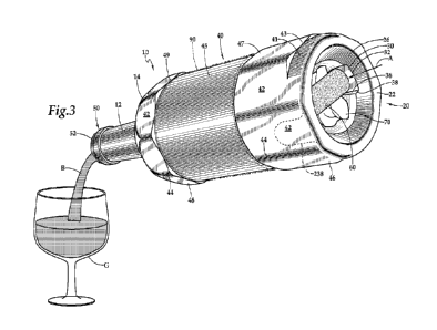
Figure 3 is a perspective view of the wine bottle of Figure 1 in use pouring
wine
from the bottle (or other beverages), and with a cork retainer holding a cork
and foil
within a punt of the bottle, according to this invention.
Figure 4 is a bottom plan view of the bottle of Figure 1 and showing a cork
retainer within the punt, without a cork therein.
Figure 5 is a bottom plan view similar to that which is shown in Figure 4, but
with a cork and foil held therein.
Figure 6 is a front elevation full section of view of a lower portion of the
bottle
of Figure 1 and showing the cork retainer within the punt of the bottle.
Figure 7 is a side elevation full sectional view of a lower portion of the
bottle of
Figure 1 and showing the cork retainer within the punt of the bottle.
Figure 8 is a sectional view similar to that which is shown in Figure 6, but
with
a cork and foil stored within the punt of the bottle.
Figure 9 is a sectional view similar to that which is shown in Figure 7, but
with
a cork and foil shown within the punt of the bottle.
Figure 10 is a top plan view of storage and/or shipping packaging for multiple
bottles and with cells of the packaging space by dividers and with bottles
within the
cells and fitting snuggly with facets of the bottles adjacent to each other.
Figure 11 is a detail of an upper portion of an alternative embodiment bottle
featuring a drip collecting a groove between two collars, the groove for
holding an
absorbing 0-ring near a lip of a finish of the bottle, and with the 0-ring not
shown.
Figure 12 is a detail similar to that which is shown in Figure 11, but with an
0-
ring in place within the groove between the upper and lower collars.
Figure 13 is a close-up detail of that which is shown in Figure 12, and with a
drip of liquid being absorbed by the 0-ring.
Figure 14 is a close-up detail of that which is shown in Figure 12, but with
the
0-ring being more toroidal rather than more cylindrical.
7
CA 03190716 2023- 2- 23
WO 2022/046619
PCT/US2021/047113
Best Modes for Carrying Out the Invention
Referring to the drawings, wherein like reference numerals represent like
parts
throughout the various drawing figures, reference numeral 10 is directed to a
bottle
featuring a cork retainer (Figures 1 and 3-5), and usable within a re-use
method
(Figure 2) to maximize sustainability and minimize waste and unnecessary
burdens in
the delivery and consumption of wine and other beverages.
In essence, and with particular reference to Figures 1 and 3, basic details of
the
bottle 10 and associated cork retainer are described, according to one
example. The
bottle 10 generally includes a neck 12 at an upper end thereof and a punt 20
at a lower
end of a body 40 of the bottle 10. Retainer surfaces 30 are located within the
punt 20
and are spaced from each other and oriented to allow a cork 60 to fit
frictionally
between these retainer surfaces 30, such as after the cork 60 has been removed
from
an opening at a top of the neck 12 of the bottle 10. A finish 50, 150 of the
bottle 10
can in one embodiment support an 0-ring 155 having a liquid absorbent
character.
The 0-ring 155 can keep a drip D from falling down onto the body 40 of the
bottle 10
after the beverage B has been poured at least partially from the bottle 10.
Foil 70,
overlying the cork 60 after cork 60 removal, can also be stored within the
punt 20 and
above the cork 60 when the cork 60 is wedged between the retainer surfaces 30
of the
cork retainer within the punt 20.
More specifically, and with initial reference to Figures 1 and 3, basic
details of
the bottle 10 are described, according to one illustrated embodiment. The
bottle 10 is
an elongate hollow structure formed of glass surrounding an interior 16
(Figures 6-9).
The bottle 10 can have any of a variety of different sizes, but would
typically be a
standard wine bottle size, such as 750 mL. The bottle 10 includes a neck 12 at
an
upper portion thereof extending from a shoulder 14 above a body 40 to a finish
50,
defining an upper end of the neck 12.
The neck 12 includes an outer wall which typically tapers somewhat from the
shoulder 14 to the finish 50. A lip 52 on the finish 50 defines a perimeter of
an
opening extending into the interior 16 of the bottle 10. This opening inboard
of the
lip 52 supports a cork 60 therein, when the bottle 10 is sealed at the winery
or other
filling location. Typically, the bottle 10 is substantially radially
symmetrical and
elongate in form with a height three or more times greater than a width.
8
CA 03190716 2023- 2- 23
WO 2022/046619
PCT/US2021/047113
A body 40 of the bottle 10 is located below the shoulder 14. This body 40 is
generally cylindrical in form and outboard of a main compartment of the
interior 16
of the bottle 10, where a majority of the wine or other beverage B is located
when
stored within the bottle 10. The bottle 40 has an outer surface which
generally
supports an area where a label can be placed, also known as a label region 45.
Details
of the particular body 40 according to one embodiment of this invention are
described
in detail below.
A lower end of the body 40 terminates at a heel 22 defining a lowermost
portion
of the bottle 10. The heel 22 defines a portion of the bottle 10 which can
rest upon an
underlying surface, such as a tabletop. The heel 22 defines a lowermost
portion and
perimeter of a punt 20. The punt 20 is a concave structure extending up into
an area
inboard of outer walls of the body 40, at least somewhat. This recess of the
punt 20
terminates at an apex 24 defining an upper end of the punt 20. Tapering sides
26
extend from the heel 22 to the apex 24. Typically these tapering sides 26 are
substantially radially symmetrical. Various different bottles 10 have punts 20
of
different sizes. The punt 20 generally has a volume which is subtracted from
interior
space inboard of the body 40 of the bottle 10, along with wall thicknesses, to
arrive at
a volume of the bottle 10 interior 16 (along with a volume contained within
portions
of the bottle 10 inboard of the shoulder 14 and neck 12 of the bottle 10).
With particular reference to Figures 3-9, details of a retainer within the
punt 20,
for holding the cork 60 therein, are described, according to one example
embodiment.
The punt 20 in the bottle 10 of this invention is modified from prior art
punts 20 to
include a retainer therein for holding a cork 60 with the punt 20. This
retainer
primarily is formed of retainer surfaces 30 formed in the tapering sides 26 of
the punt
20. These retainer surfaces 30 are preferably similar to each other in size
and shape,
and oriented parallel to each other and facing each other. A spacing between
these
retainer surfaces 30 is preferably similar to a length of the cork 60 between
ends of
the cork 60. Each retainer surface 30 has a size and width similar to a width
of the
cork 60, generally defined by a diameter of a cylindrical sidewall of the cork
60,
which extends between the ends of the cork 60.
As an alternative, the retainer surfaces 30 could be spaced apart by a width
of
the cork 60 rather than its length. As an option, the retainer surfaces 30 (or
at least
one of them) could be eliminated. In its place, the punt 20 could extend
laterally
9
CA 03190716 2023- 2- 23
WO 2022/046619
PCT/US2021/047113
(along a centerline of the cork 60) to an exterior of the body 40 of the
bottle 10. The
cork 60 could be seen in this embodiment, at least one end thereof. Such an
alternate
retainer surface 236 is shown in broken lines in Figures 3-9. The interior 216
could
be modified correspondingly, as also shown in broken lines. Such an
alternative
allows the cork 60 to be seen and also facilitates larger corks 60 and/or
smaller
bottles.
Each retainer surface 30 preferably includes a lower edge 32 which fades into
lower portions of the tapering sides 26 of the punt 20, just above the heel
22. Ends of
the cork 60 can thus readily slide up into the punt 20 and over the lower edge
32 to
come into a friction fit adjacent to each of the retainer surfaces 30. An
upper portion
of the retainer surfaces 30, opposite the lower edge 32 is defined by a vault
34. This
vault 34 is preferably a curving structure with a radius of curvature similar
to a radius
of curvature of the cylindrical sidewall of the cork 60 adjacent to the ends
of the cork
60. In this way, the cork 60 can slide up, wedged between the retainer
surfaces 30,
until the ends of the cork 60 about the vault 34 along an entire surface of
the vault 34.
Sidewalls 36 of each retainer surface 30 extend from the vault 34 down to a
foot
38 adjacent to the lower edge 32. The sidewalls 36 are perpendicular to the
retainer
surfaces 30 and extend within substantially vertical planes which are parallel
and
spaced from each other for each of the retainer surfaces 30. The sidewalls 36
act as
guide abutments, keeping the ends of the cork 60 aligned within a center of
the
retainer and a center of the retainer surfaces 30, as the cork 60 moves upward
into the
retainer. While the sidewalls 36 can be parallel with each other, in one
embodiment,
the sidewalls 36 are slightly further from each other adjacent to the foot 38
than
adjacent to the vault 34, to assist in ensuring the cork 60 is guided into the
retainer,
but still leaving the end of the cork 60 fully supported once the cork 60 has
been
inserted (along arrow A of Figures 3, 8 and 9) up into the retainer and
abutting the
vault 34.
While the retainer surfaces 30 are preferably substantially parallel with each
other, the retainer surfaces 30 can be slightly further from each other at the
lower
edges 32 thereof than at the vault 34 thereof. In this way, the cork 60
initially readily
fits into lower portions of each retainer surface 30, but then the cork 60
becomes more
and more tightly held within the retainer as the cork 60 is moved upward
(along arrow
A) toward the vault 34, for secure holding of the cork 60. Most preferably,
this
CA 03190716 2023- 2- 23
WO 2022/046619
PCT/US2021/047113
spacing between the retainer surfaces 30, at least adjacent to the vault 34,
is slightly
less than a length between ends of the cork 60, so a friction fit is provided,
holding the
cork 60 securely within the retainer and abutting each of the retainer
surfaces 30.
The retainer surfaces 30 are sufficiently far up into the punt 20, that the
cork 60
is entirely above the heel 22 when placed within the retainer of the punt 20.
The
retainer surfaces 30 are sufficiently low within the punt 20 to leave space
above the
retainer surfaces 30 of the retainer and below the apex 24 of the punt 20.
This space
above the retainer can support the foil 70, pinched between the apex 24 and
the cork
60, so that the foil 70 does not need to be thrown away or recycled by a user
of the
bottle 10, but rather can be returned, along with the cork 60 and the bottle
10, either
for re-use or recycling in a most efficient manner along with other similar
foils of
other bottles at a centralized return location.
The retainer surfaces 30 can be formed by casting, such as along with casting
of
the entire bottle, or can be formed by machining, such as in a separate
procedure
performed after the bottle is formed. Other forms of manufacture of the
retainer
surfaces 30, could include formation by additive manufacturing, where surface
portions of the punt 20 would be built up in an additive manufacturing
process, and
leaving out space for the retainer surfaces 30, to provide the retainer
function of this
invention. While the retainer surfaces 30 are disclosed in this embodiment as
recesses
extending into material forming the bottle 10, it is conceivable that the
retainer
surfaces 30 could instead be built out of adjacent surface portions of the
bottle 10
within the punt 20, or the retainer surfaces 30 could be a combination of cut
into a
surface of the bottle and extending out of a surface of the bottle within the
punt 20.
The retainer surfaces could optionally be curved cylindrically (about a
vertical central
axis), if configured to hold the cork 60 between sides of the cork 60 rather
than the
ends.
With particular reference to Figures 1 and 3-5, particular details of the body
40
are described in one embodiment of this invention. While the bodies of bottles
10,
such as wine bottles, are typically cylindrical in form, an embodiment of the
body 40
disclosed herein is faceted to have an outer contour which is octagonal in
cross-
sectional form (when viewed with a horizontal cross-section). The body 40
preferably has three regions including a label region 45 at a middle elevation
of the
body 40, and with a lower region 46 below the label region 45 and an upper
region 48
11
CA 03190716 2023- 2- 23
WO 2022/046619
PCT/US2021/047113
above the label region 45. The lower region 46 extends from the label region
45
down to the heel 22 of the bottle 10. The upper region 48 extends from the
label
region 45 up to the shoulder 14. The label region 45 extends between the lower
region 46 and upper region 48. A lower transition 47 is located between the
lower
region 46 and the label region 45. An upper transition 49 is located between
the label
region 45 and the upper region 48.
In this embodiment, the label region 45 is substantially perfectly cylindrical
in
form, having a constant width which is slightly less than an average width of
the
upper region 48 and lower region 46. In this way, a label can be placed over
the label
region 45, with the label 90 (Figure 3) held in place by the lower transition
47 and
upper transition 49, and not requiring adhesive to hold directly to the
bottle. In this
way, when the bottle 10 is re-used, no adhesive needs to be removed or
otherwise
factored into such re-use.
In one embodiment, the label 90 can be a band of material which is slightly
stretchable and formed without a seam. Such a label 90 can slide over the
lower
region 46 or the upper region 48 and resiliently return to an original
diameter to
tightly fit over the label region 45. In another embodiment, the label 90
includes at
least portions thereof which can be caused to shrink after placement of the
label 90
adjacent to the label region 45. For instance, the label could be formed of at
least
partially plastic hydrocarbon material which has a shrinking characteristic
when heat
is applied. Such a label can first be placed loosely over the label region 45,
and then
can have heat applied until the label shrinks and tightly fits within the
label region.
In another embodiment, the label 90 begins as a planer strip of paper and
adhesive is used to bond one lateral edge of the label to an opposite lateral
edge of the
label. In such an arrangement, no adhesive is required between the bottle and
the
label 90, but rather adhesive is only provided between two portions of the
label 90,
and no adhesive needs to be removed from the bottle 90.
In another embodiment, an adhesive is utilized to hold the label 90 in place,
at
least partially, which adhesive is designed to be readily removable, such as
by
application of mild heat. In this way, a hot water and/or steam sterilizing
process for
the bottle 10 would readily remove any such adhesive which was previously used
to
hold the label 90 in place. Furthermore, any such label adhesive can be formed
of a
biodegradable and/or a naturally occurring substance, such that sustainability
is
12
CA 03190716 2023- 2- 23
WO 2022/046619
PCT/US2021/047113
maintained for the overall bottle 10 and label 90, and with little or no
environmental
impact associated with utilization of the adhesive.
The upper region 48 and lower region 46 are preferably faceted with eight
facets
42 spaced from each other by corners 44. These corners 44 are preferably
rounded,
but still leave a majority of the outer surface of the body 40 located within
the facets
42 of planar form. At the transitions 47, 49, the facets 42 and corners 44
transition
gradually into the cylindrical form of the label region 45. At upper portions
of the
upper region 48 and lower portions of the lower region 46, the facets 42 and
corners
44 transition into either the shoulder 14 for the upper region 48 or the heel
22 for the
lower region 46. A band 41 is provided in one embodiment just above the heel
22
which is semi-cylindrical in form, and interrupting at least some of the
facets adjacent
to the heel 22, which band can allow for rotational alignment of the bottle 10
within
automated bottle 10 handling equipment.
The octagonal body 40 outer surface, defining approximately half of an outer
surface of the body 40 of the bottle 10 has a variety of benefits. The facets
42 and
corners 44 can provide a somewhat more tactile surface for a user to more
readily
grasp the bottle 10 during use, and to diminish risk that the bottle 10 will
slip out of a
hand of a user. If the bottle 10 is laying on a horizontal surface, such as a
tabletop, it
is prevented from rolling, but rather will settle onto one of the facets 42.
This can
prevent the bottle 10, should it be placed on its side or fall onto a side,
from rolling to
an edge of a table and then falling to the floor, where it might potentially
break, or
cause an injury.
Furthermore, and as depicted in Figure 10, the bottle 10 can conveniently be
transported and/or stored within packaging 100 which more safely carries a
group of
bottles 10 with limited packaging 100, compared to what would be the case with
cylindrical bottles 10. In particular, the packaging 100 includes outer walls
120 with
dividers 110 dividing the packaging 100 and separate cells. Each cell can hold
one
bottle 10 therein.
Figure 10 depicts a top plan view of such packaging 100 with six cells and
with
one bottle within each of the six cells. In this embodiment, the cells are all
square in
horizontal cross-section. Facets 42 of each bottle 10 are aligned with each
other so
that half of the facets are parallel with and abutting either a portion of a
divider 110 or
a portion of the outer wall 120, in a parallel plane-to-plane abutting
orientation. With
13
CA 03190716 2023- 2- 23
WO 2022/046619
PCT/US2021/047113
respect to the dividers 110, facets 42 of bottles 10 are provided on either
side of each
divider 110 in a planar adjacent orientation.
One significant risk when transporting bottles within packaging is that the
bottles 10 will slam together with sufficient force during transport, that the
bottles
will break. Cylindrical bottles, placed adjacent to each other, have forces
there
between concentrated along very exceptionally small areas on an exterior of
the
bottles. This leads to stress concentration and a heightened potential for
breakage.
Even if the bottles 10 do not break, these small abutting surfaces arc highly
likely to
be scratched/etched in a manner which scuffs up the bottles and makes them
less
desirable in appearance. Such contact between bottles can also damage the
labels
placed on exteriors thereof. Consumers often have less of a preference for
drinking
wine from the bottle which is scuffed up or has a torn label or other wear
visible on an
exterior thereof.
Consumers of wine or other beverages from such a bottle are likely to wonder
what other defects are associated with the lack of care which resulted in the
bottle
damage. To prevent this, excessive packaging 100 can be utilized, but has
additional
cost, weight for transport, and waste when the packaging 100 is disposed of.
With
this invention, the facets 42 of the multiple bottles 10 are brought adjacent
to each
other in a co-planar fashion, so that forces exchanged therebetween are spread
out
over the large surface area of the facets 42. A small divider 110, or even no
divider
can be provided and damage is avoided. Such avoidance of damage to the bottles
10
further facilitate re-use of the bottles 10, such as by cleaning and refilling
thereof, a
large number of times, without damage to the bottles 10.
The packaging 100, in various embodiments, could have beveled corners so that
corner cells have one beveled corner and corner cells of the packaging 100
would be
adjacent to facets 42 of the bottles 10 on at least one additional facet 42.
As a further
option, each exterior corner of the cells could be beveled to still further
hold and
support the bottles 10. In one embodiment, the packaging is flexible plastic
which
can be rolled up to fit within a cell of another package for return for re-use
or
recycling.
With particular reference to Figures 11-14, details of an alternative
embodiment
finish 150 for an upper end of the neck 12 of the bottle 10 as described. This
alternative finish 150 supports an 0-ring 155 which is of at least partially
absorbent
14
CA 03190716 2023- 2- 23
WO 2022/046619
PCT/US2021/047113
character, to catch a drip D which commonly attempts to roll down an exterior
of the
neck 12 of the bottle 10 (Figure 13) after pouring a beverage B (Figure 3).
The finish
150 in this embodiment includes a lip 152 surrounding an opening into which
the cork
60 is removed, before pouring wine or other beverage B from the bottle 10
(Figure 3).
The finish 150 includes an upper collar 154 and a lower collar 156 with a
groove 158
between the upper collar 154 and lower collar 156. Each of these collars 154,
156 is
cylindrical in form and the groove 158 is also cylindrical in form. The upper
collar
154 preferably has a slightly larger diameter to help to hold the foil 70
(Figure 1) and
to hold the 0-ring 155 within the groove 158. As an alternative, the collars
154, 156
could have the same diameter.
A cylindrical 0-ring 155 fits within this groove 158 between the upper collar
154 and lower collar 156. While 0-ring 155 is shown as having a cylindrical
form, it
could alternatively have a more toroidal form and still fit within groove 150
and
function according to this invention. At a minimum, the 0-ring 155 forms a
circuit
which can reside within a groove 158 of some shape between an upper collar 150
or a
lower collar 156 which define raised portions of the finish 150 of the neck
12.
The 0-ring 155 is preferably formed of a sufficiently resilient material that
it
can be snapped into place within the groove 158 and hold its position within
this
groove 158, after appropriate forces are applied to stretch 0-ring 155 and
move the 0-
ring over the upper collar 154. The 0-ring 155 preferably has some absorbency
characteristics, so that a drip D falling down the neck 12 of the bottle 10
(Figure 13)
is absorbed by the 0-ring 155. In one embodiment, the 0-ring 155 is
sufficiently
absorbent to catch a half dozen drips, so that the 0-ring 155 is not saturated
until the
bottle 10 has been drained of wine or other beverage B. In one embodiment, the
0-
ring 155 primarily relies upon capillary action and the small space between
the collars
154, 156, groove 158 and 0-ring 155 to hold the liquid therein, rather than,
or in
addition to any absorbency of the material forming the 0-ring 155.
The 0-ring 155 is shown in Figures 12 and 13 with a cylindrical form, mostly
filling the groove 150. In Figure 14 and alternative 0-ring 255 has a toroidal
form.
With such a toroidal form, larger void space for holding "drips" could be
provided.
In one embodiment, the 0-ring 155 has an outer surface thereof printed with
text 157. In one embodiment, this text 157 is in the form of hidden text, such
as text
printed out of lemon juice or some other material which is capable of being
printed
CA 03190716 2023- 2- 23
WO 2022/046619
PCT/US2021/047113
and which is generally invisible when dry. This hidden text 157 can be
selected so
that when it comes into contact with liquid of any type, or when it comes into
contact
with liquid of a particular type, such as wine, that the text transitions from
being
hidden to being visible. In this way, the hidden text 157 can have a message
which is
hidden until a drip D contacts the 0-ring 155, causing the hidden text 157 to
transition
from being hidden text 157 to being visible text. Such a hidden text can, once
revealed, provide another aspect of enjoyment to consumers of the wine or
other
beverage B contained with in the bottle 10.
In various embodiments, the secret text 157 could, rather than being text,
merely
be a decorative/ornamental pattern and/or design. As another alternative, the
0-ring
155 could be formed of pH test material which exhibits a color corresponding
with a
pH level of the wine or other beverage constituting the drip D. In this way,
analytical
information would be conveyed to a consumer of the beverage B constituting the
drip
D.
In use and operation, the bottle 10 of this invention along with a cork 60 and
foil
70 can be used and re-used according to a re-use method 80 (Figure 2) which
allows
for a most sustainable overall methodology for enjoying wine or other bottle
10
contained beverages B. Initially, the wine bottle 10 is filled with wine, such
as at a
central filling location, which would typically be a winery. Either before or
after
filling the wine bottle, a label 90 is applied to the bottle 10. After filling
of the bottle
10, a cork 60 is fitted on the bottle 10 to close an interior of the bottle
10. Foil 70 is
typically provided over the cork 60. While wine bottles 10 could be delivered
in
various different quantities to consumers in various different ways, according
to one
embodiment of this invention, multiple bottles 10 are placed within packaging
100,
such as that depicted in Figure 10 and described in detail above. The shipping
container is sent to a consumer. The consumer can keep the wine bottles 10
within
this packaging 100 if desired, or can keep the packaging 100 as a receptacle
for the
bottles 10 after they have been emptied, such as for consumption of the wine
or other
beverage B within the bottles 10 (Figure 3).
A goal of the re-use method of this invention is to reduce to zero (or near
zero)
the waste associated with enjoying wine or other beverage B from the bottle
10. To
keep the cork 60 and foil 70 from becoming waste products, and to provide a
convenient location for placement of the cork 60 after it is removed from the
neck 12
16
CA 03190716 2023- 2- 23
WO 2022/046619
PCT/US2021/047113
of the bottle 10, a consumer removes the foil and cork from the neck 12 of the
bottle
and places the cork within the retainer in the punt 20 of the bottle 10, with
the foil
70 folded up and trapped above the cork 60. The wine or other beverage B can
then
be poured from the bottle 10, into a glass G or other drinking article, for
enjoying of
5 the
beverage B (Figure 3). After the bottle 10 is empty, the bottle 10 can be
returned
to one of the cells of the packaging 100. When the packaging 100 is full of
bottles 10,
this packaging 100 can be used to transport the load of bottles 10 back to the
winery
or other filling location, or other re-use location.
In one embodiment, and for maximum sustainability and efficiency, a delivery
10
service is provided which transports a new order of wine bottles 10 in a new
package
100 to the consumer, and when arriving at the consumer location, picks up
packaging
100 full of empty bottles 10. In this way, transportation personnel are
beneficially
only utilizing transportation resources to carry useful loads in both
directions, rather
than having extra trips where nothing beneficial is being carried.
Because of the unique shape of the bottles 10, as described above, the
packaging
100 has a minimal amount of material associated therewith and avoids scuffing
or
other damage. At the winery or other re-use location, the bottles 10 are
removed from
the packaging 100. Corks are removed from the retainers in the punts 20 of the
bottles 10 and the corks 60 can be recycled together in a most efficient
manner. In
one embodiment, this would involve grinding up of the cork material and
utilization
of the ground up cork material in foimation of new synthetic corks. In another
embodiment, such as if the cork is a natural material, it can be converted
into articles
from which recycled cork can be made, or can be disposed of, due to its
biodegradable natural nature, in a sustainable manner. The foil 70 can
similarly be
repurposed or recycled along with other foil 74, maximizing efficiency in such
recycling. Furthermore, the labels 90 can be removed from the bottles and
recycled
or responsibly disposed of or re-purposed.
The bottle 10 can be thoroughly cleaned utilizing a variety of different
processes, and does not need to be crushed and reconstituted into a new bottle
10, but
rather can readily be refilled after appropriate cleaning/sterilization has
occurred. The
filled bottle 10 can have a new label 90 placed thereon and a new cork 60 and
foil 70
applied thereto. When the wine or other beverage B is ready and a consumer is
identified, the refilled bottle 10 of a re-used nature can be shipped back to
a consumer
17
CA 03190716 2023- 2- 23
WO 2022/046619
PCT/US2021/047113
(or retail establishment) to repeat the process. While a retail consumer is
described
above, an intermediate retail store, or restaurant or other location could
similarly
function as the consumer or as an intermediary between the winery and the
consumer.
This disclosure is provided to reveal a preferred embodiment of the invention
and a best mode for practicing the invention. Having thus described the
invention in
this way, it should be apparent that various different modifications can be
made to the
preferred embodiment without departing from the scope and spirit of this
invention
disclosure. When structures are identified as a means to perform a function,
the
identification is intended to include all structures which can perform the
function
specified. When embodiments are referred to as "exemplary" or "preferred" this
term
is meant to indicate one example of the invention, and does not exclude other
possible
embodiments. When structures of this invention are identified as being coupled
together, such language should be interpreted broadly to include the
structures being
coupled directly together or coupled together through intervening structures.
Such
coupling could be permanent or temporary and either in a rigid fashion or in a
fashion
which allows pivoting, sliding or other relative motion while still providing
some
form of attachment, unless specifically restricted.
25
18
CA 03190716 2023- 2- 23
WO 2022/046619
PCT/US2021/047113
Industrial Applicability
This invention exhibits industrial applicability in that it provides a wine
bottle
which has a cork retainer within a punt of the wine bottle.
Another object of the present invention is to provide a \vine bottle which is
configured and optimized for re-use.
Another object to the present invention is to supply wine or other beverages
contained within bottles in a way which is highly sustainable, with a minimal
energy
footprint and materials utilization footprint.
Another object of the present invention is to provide a method for delivery,
return and re-use of wine bottles.
Another object of the present mention is to provide a wine bottle which has a
label which is easy to remove, without requiring adhesive adhering to the
bottle itself.
Another object of the present invention is to provide a wine bottle which is
shaped to avoid scuffing or other damage when the bottle comes into contact
with
other similar bottles.
Another object of the present invention is to provide a system and method for
holding a cork when it is not in use, so that it is ready to be re-used in
closing an
opening into a bottle, if not all of the contents of the bottle are used at
one time.
Another object of the present invention is to provide a system and method for
storing both a cork and foil of a beverage bottle after they have been removed
from an
opening on a neck of the bottle, to best facilitate re-use and/or recycling of
the bottle,
cork and/or foil (as well as the label).
Other further objects of this invention which demonstrate its industrial
applicability, will become apparent from a careful reading of the included
detailed
description, from a review of the enclosed drawings and from review of the
claims
included herein.
19
CA 03190716 2023- 2- 23