Note: Descriptions are shown in the official language in which they were submitted.
CA 03190785 2023-02-03
WO 2022/029401
PCT/GB2021/051697
- 1 -
TITLE
Wind channelling and directing structures
DESCRIPTION
Technical Field
The present invention relates to structures for channelling and directing
incident wind.
Summary of the Invention
The present invention provides a structure for channelling and directing
incident wind
comprising:
a hollow pipe having a downstream end that defines at least one outlet, and an
upstream end; and
a rotatably mounted intake at the upstream end of the pipe adapted to direct
incident wind into the pipe.
The present invention may further provide a method of channelling and
directing
incident wind through a hollow pipe having a downstream end that defines at
least
one outlet, and an upstream end, wherein incident wind is directed into the
pipe
through a rotatably mounted intake provided at the upstream end of the pipe.
The intake may include an opening (or vent) through which incident wind enters
the
intake and an internal structure that directs the wind from the opening
towards the
upstream end of the pipe.
.. The opening may have any suitable shape, e.g., it may be substantially
circular, oval,
rectangular or triangular. The intake itself may have any suitable shape and
configuration.
The opening may be formed in an angled front part of the intake, i.e., the
part which
faces into the wind in use.
The intake may be rotatably mounted about a vertical axis.
CA 03190785 2023-02-03
WO 2022/029401
PCT/GB2021/051697
- 2 -
The intake may be rotatably mounted relative to the fixed or stationary pipe
by any
suitable means such as a bearing. The intake may be driven to rotate by
sensing wind
direction and rotating the intake using an actuator such as an electric motor
(sometimes called a "yaw motor") that is controlled by a suitable controller
so that the
intake opening faces the wind direction. A wind sensor may be provided to
measure
wind direction for this purpose. The wind sensor may also measure wind speed
for
adjusting the angle of the slats of a louvre assembly ¨ see below. The intake
may also
comprise a directional vane (or fin) that enables the incident wind to rotate
the intake
.. so that the intake opening faces the wind direction. The directional vane
may have
any suitable shape.
A louvre assembly may be used to control the amount of incident wind that is
permitted to enter the intake opening, and hence the amount of incident wind
that is
directed to the upstream end of the pipe. It will be understood that it may be
necessary to limit or restrict the amount of wind entering the intake to avoid
damaging
the structure and any equipment located downstream of the outlet(s). In
general
terms, any suitable means can be provided for controlling the amount of
incident wind
that enters the intake or the upstream end of the pipe and it is not limited
to a louvre
assembly. The means may form part of the intake opening or be positioned in
front of
the intake opening.
The louvre assembly may include a plurality of individual slats that are
pivotally
mounted so that their angle may be adjusted by a suitable adjustment
mechanism.
The individual slats may be adjusted by pivoting them in the same direction or
by
pivoting adjacent slats in the opposite direction. The ends of each slat may
be
pivotally mounted in a support or frame, which may be integral with the
intake. The
adjustment mechanism may be configured to pivot one of the slats if the slats
are
connected together in such a way ¨ either directly or indirectly ¨ that allows
all of the
.. slats to be pivoted in unison.
CA 03190785 2023-02-03
WO 2022/029401
PCT/GB2021/051697
- 3 -
The slats may be pivoted between a closed position where the slats lie
substantially in
the same plane and will often overlap slightly to form a closed barrier to
prevent wind
from entering the intake, and a fully open position where the slats define a
plurality of
open channels therebetween to allow substantially all of the incident wind to
enter the
intake. The louvre assembly, and in particular the slats, may cover
substantially all,
or just part, of the intake opening.
The angle of the slats may be adjusted based on wind speed ¨ e.g., so that the
slats are
fully open when the wind speed is below a lower threshold and are closed when
the
wind speed is above an upper threshold. When the wind speed is greater than
the
lower threshold but less than the upper threshold, the slats may be adjusted
gradually
from the fully open position towards the closed position with increasing wind
speed
and vice versa. In one arrangement, the lower threshold and the upper
threshold may
be substantially the same so that the slats are adjusted from being fully open
to being
.. closed and vice versa ¨ optionally with some "hysteresis" to prevent
continual and
rapid opening and closing of the slats when the wind speed is around the
threshold
level.
In one arrangement, the angle of the slats may be adjusted based on the wind
speed
.. provided by the wind sensor. The adjustment mechanism which adjusts the
angle of
the slats may include an actuator such as an electric motor that is controlled
by a
suitable controller based on the wind speed. Other actuators might include
pneumatic,
hydraulic or electro-mechanical actuators, for example.
In one arrangement, the angle of the slats may be adjusted mechanically based
on the
wind speed using a wind resistance plate as a mechanical actuator, for
example. The
adjustment mechanism may include a pivotally mounted wind resistance plate
whose
angle varies with wind speed. (It will be readily understood that wind force
is
proportional to wind speed ¨ consequently, a higher wind speed will equate to
a
greater wind force acting on the wind resistance plate and vice versa.) The
wind
resistance plate may be mounted below the louvre assembly and the intake
opening.
The pivoting movement of the wind resistance plate may be used to adjust the
angle
CA 03190785 2023-02-03
WO 2022/029401
PCT/GB2021/051697
- 4 -
of the slats and the adjustment mechanism may include a suitable linkage such
as a
lever arm mechanism or a gearing mechanism for that purpose. The wind
resistance
plate may be biased towards a first position where the slats are in the fully
open
position, and the wind resistance plate may be pivoted towards a second
position by
the wind force applied by the incident wind. In the second position, the slats
of the
louvre assembly are in the closed position. The wind resistance plate may be
biased
towards the first position by a spring or other suitable biasing means, for
example.
The biasing means may form part of the louvre assembly, e.g., the adjustment
mechanism. It will be readily understood that the spring or other suitable
biasing
means will apply a biasing force to the wind resistance plate ¨ either
directly or
indirectly through the adjustment mechanism, for example ¨ that opposes the
wind
force that acts on the wind resistance plate. Consequently, the wind
resistance plate
will only be pivoted towards the second position if the wind force acting on
the wind
resistance plate exceeds the biasing force.
The wind resistance plate may be substantially L-shaped. In one arrangement,
the
wind resistance plate is designed so that the incident wind impinges on a
first (or
substantially vertical) part of the L-shaped wind resistance plate. The
incident wind
may pivot the first part of the wind resistance plate backwards to a second
position
where the slats are in the closed position. Incident wind that impinges on the
first part
of the wind resistance plate may be guided along a second (or substantially
horizontal) part of the plate ¨ and is preferably directed in the opposite
direction to the
wind direction (i.e., back towards the incident wind). In general terms, the
incident
wind that impinges on the first part of the wind resistance plate is
preferably directed
away from the intake by the second part. Incident wind that impinges on the
closed
slats may also be directed downwardly towards the L-shaped wind resistance
plate ¨
for example, if the louvre assembly is angled to follow the angled front part
of the
intake ¨ and then directed in the opposite direction to the wind direction. If
the wind
speed falls below the upper threshold, the wind resistance plate may pivot
back to the
first position where the slats are fully open under the action of the biasing
force. The
interior angle between the first and second parts of the L-shaped wind
resistance plate
may be between about 60 and about 120 degrees, for example.
CA 03190785 2023-02-03
WO 2022/029401
PCT/GB2021/051697
- 5 -
The upstream end of the pipe may be substantially vertical and may be designed
to
rotatably mount the intake. The downstream end of the pipe may be
substantially
vertical or horizontal ¨ i.e., so that in the latter case the pipe has a
change of direction
with a curved part. The pipe may have any suitable cross-section, but a
substantially
circular cross-section will generally be preferred.
The pipe may be formed of any suitable rigid material.
The pipe may be formed from a plurality of individual pipe sections. The pipe
sections may be mechanically connected together ¨ e.g., using outwardly
extending
connecting flanges which receive mechanical fixings such as bolts. As noted
above,
the pipe sections may be straight or curved, for example.
The pipe sections may have different internal diameters (or cross-sectional
areas).
For example, a pipe section located at or near the upstream end of the pipe
may have a
larger internal diameter (or cross-sectional area) than a pipe section located
at or near
the downstream end of the pipe. In this way, the internal diameter (or cross-
sectional
area) of the pipe may be narrowed gradually along the direction from the
upstream
end to the downstream end that defines the outlet(s). Narrowing the internal
diameter
(or cross-sectional area) of the pipe results in an increase in the wind
velocity through
the pipe in the downstream direction towards the outlet(s) and in a
corresponding
reduction in pressure.
Each pipe section may have the same internal diameter (or cross-sectional
area)
throughout its axial extent, or the internal diameter (or cross-sectional
area) may vary
¨ preferably the internal diameter (or cross-sectional area) will decrease in
the
downstream direction. Pipe sections may be connected together by intermediate
sections (or couplers) which may, in particular, be used to connect straight
pipe
sections having different but non-varying internal diameters (or cross-
sectional
areas). The intermediate sections may have a frusto-conical inner surface (or
sloping
or angled inner surface(s)) to channel (or "funnel") the wind from one pipe
section to
CA 03190785 2023-02-03
WO 2022/029401
PCT/GB2021/051697
- 6 -
another. The wind velocity may increase within the intermediate sections. The
intermediate sections and the pipe sections may be mechanically connected
together ¨
e.g., using outwardly extending flanges which receive mechanical fixings such
as
bolts.
At least part of the pipe (e.g., one or more pipe sections) may include an
internal
helical flange or an internal helical groove (or "rifling" groove) to promote
helical
movement of the wind through the pipe. It is believed that promoting such
helical
movement, where the wind has both a linear and rotational component of
movement
from the upstream end of the pipe toward the downstream end, will reduce the
turbulence within the hollow pipe and will help to move the incident wind
through the
pipe as efficiently as possible. It may also help to remove any particulates,
debris or
liquid droplets that are entrained in the wind, and in particular where the
rotational
effect of the wind can be used to expel the particulates, debris or liquid
droplets
through openings or slots in the pipe ¨ see below. The pipe may include a
plurality of
separate helical flanges. Each flange may extend substantially perpendicular
to the
inner surface of the pipe and may be welded to the inner surface, for example.
Each
flange may have the same width throughout its helical extent, or the width may
vary ¨
preferably the width will increase in the downstream direction. (In other
words, the
flange may extend further into the hollow interior of the pipe at the
downstream end
of the flange than it does at the upstream end of the flange.) An internal
helical flange
may be omitted in some parts of the pipe, e.g., in any intermediate sections
(or
couplers) or any curved parts of the pipe. If a helical groove is provided, it
may
typically be in a downstream part of the pipe such as in the pipe section that
defines
the outlet, for example.
The vertical part of the pipe may be supported by a frame or support
structure.
The pipe may include openings or slots through which any entrained
particulates,
debris or liquid droplets (and a small quantity of wind) may be ejected. If
the pipe
includes a change of direction, the openings or slots may be positioned in the
curved
part of the pipe. The openings or slots may in particular be positioned in the
radially
CA 03190785 2023-02-03
WO 2022/029401
PCT/GB2021/051697
- 7 -
outer part of the curved part of the pipe. Openings or slots may also be
provided in
one or more of the straight pipe sections.
If the pipe includes an internal helical flange, the openings or slots in the
pipe may be
aligned with the helical channel defined by the internal helical flange. But
it will be
understood that the openings or slots may have any suitable alignment.
The structure may include at least one filter screen to prevent larger
particulates and
debris from entering the pipe. The filter screen may be located at the
upstream end of
the pipe or in the intake, for example.
The downstream end of the pipe may be divided to define two or more outlets.
The structure may form part of a wind turbine, for example. In particular, the
wind
turbine may further include a turbine assembly positioned at the outlet of the
structure
and adapted to be rotated by the wind exiting the outlet. The pipe may be
positioned
to channel and direct the wind on to the turbine assembly. The wind turbine
may
further include a rotating electrical machine (e.g., a generator) including a
rotor and a
stator, where the rotor is adapted to be driven to rotate by the turbine
assembly to
generate electricity. The turbine assembly and the rotating electrical machine
may be
conveniently located at low level as opposed to being housed in a nacelle or
casing on
the top of a tower as would normally be the case for a conventional wind
turbine.
The structure may form part of a ventilation or cooling system, for example.
Drawings
Figure 1 is a side view of a structure according to the present invention;
Figure 2 is a perspective view of the intake of the structure of Figure 1;
Figure 3 is a side view of the intake of Figure 2 with the wind resistance
plate in a
first position and the slats of the louvre assembly in an open position;
Figure 4 is a front view of the intake of Figure 3;
CA 03190785 2023-02-03
WO 2022/029401
PCT/GB2021/051697
- 8 -
Figure 5 is a side view of the intake of Figure 2 with the wind resistance
plate in a
second position and the slats of the louvre assembly in a closed position;
Figure 6 is a front view of the intake of Figure 5;
Figure 7 is a perspective view of an alternative intake;
Figure 8 is a front view of the alternative intake of Figure 7;
Figure 9 is a side view of a straight pipe section;
Figure 10 is a cross-section view of the straight pipe section of Figure 9;
Figure 11 is a perspective view of the straight pipe section of Figures 9 and
10;
Figure 12 is a side view of a coupler;
Figure 13 is a cross-section view the coupler of Figure 12;
Figure 14 is a perspective view of a curved pipe section; and
Figure 15 is a perspective view of part of a straight pipe section showing
slots.
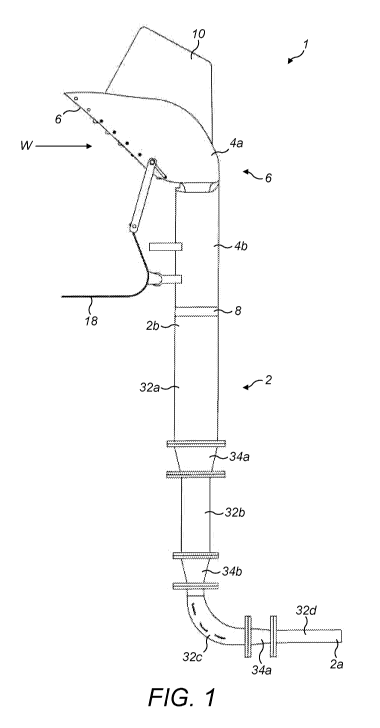
With reference to Figure 1, the present invention provides a structure 1 for
channelling and directing incident wind comprising a hollow pipe 2 and an
intake 4.
The pipe 2 has a downstream end 2a that defines an outlet, and an upstream end
2b.
The intake 4 is rotatably mounted at the upstream end 2b of the pipe and is
adapted to
direct incident wind (which is indicated by arrows labelled "W" in the
Figures) into
the pipe 2. The intake 4 includes a "head" part 4a and a "neck" part 4b that
is formed
as a hollow vertical pipe.
With reference to Figures 2 to 6, the head part 4a of the intake 4 includes a
housing
that defines an opening or vent 6 through which incident wind enters the
intake, and
an internal structure that directs the wind from the opening into the neck
part 4b and
towards the upstream end 2b of the pipe 2. The opening 6 shown in Figures 2 to
6 is
substantially rectangular, but it will be understood that it may have any
suitable shape.
The opening 6 is formed in an angled front part of the head part 4a as shown.
The
upper part of the head part 4a of the intake 4 therefore overhangs the louvre
assembly
12 ¨ see below ¨ to protect it and help prevent rain from entering the neck
part 4b.
CA 03190785 2023-02-03
WO 2022/029401
PCT/GB2021/051697
- 9 -
The intake 4 is rotatably mounted about a vertical axis.
The neck part 4b of the intake 4 is rotatably mounted relative to the pipe 2
by a
bearing 8.
A directional vane 10 is formed on an upper part of the head part 4a of the
intake 4.
The directional vane 10 enables the incident wind to rotate the intake 4 so
that the
angled front part and the opening 6 faces the wind direction. More
particularly, if the
wind direction changes, the wind force acting on the directional vane 10 will
cause
the intake 4 to rotate to face the incident wind. It will be understood that
the intake
may also be driven to rotate by sensing wind direction (e.g., using wind
sensor) and
rotating the intake using an actuator such as an electric motor that is
controlled by a
suitable controller.
A louvre assembly 12 is used to control the amount of incident wind that is
permitted
to enter the intake opening 6, and hence the amount of incident wind that is
directed
by the intake 4 to the upstream end 2b of the pipe 2. The louvre assembly 12
includes
a plurality of individual slats 14 that are pivotally mounted so that their
angle may be
adjusted by an adjustment mechanism 16. The ends of each slat 14 are pivotally
mounted in a support or frame formed by opposite side parts of the head part
4a of the
intake 4.
The slats 14 are pivoted between a closed position where the slats lie
substantially in
the same plane and overlap slightly to form a closed and angled barrier to
prevent
wind from entering the intake 4, and a fully open position where the slats
define a
plurality of open channels therebetween to allow substantially all of the
incident wind
to enter the intake. In the louvre assembly 12 shown in Figures 2 to 6, the
slats 14 do
not cover all of the intake opening 6 so some incident wind will enter the
intake 4
even when the slats are in the closed position. But it will be understood that
the slats
can be arranged to cover substantially all of the intake opening so that
almost no
incident wind enters the intake when the slats are in the closed position.
CA 03190785 2023-02-03
WO 2022/029401
PCT/GB2021/051697
- 10 -
The angle of the slats 14 is adjusted based on wind speed ¨ e.g., so that the
slats are
fully open when the wind speed is below a lower threshold and are closed when
the
wind speed is above an upper threshold. The angle of the slats 14 is adjusted
mechanically based on the wind speed using a L-shaped wind resistance plate 18
that
forms part of the adjustment mechanism 16. The wind resistance plate 18 is
pivotally
mounted on the neck part 4b of the intake 4 by a mounting bracket. The wind
resistance plate 18 is positioned below the louvre assembly 12 and the intake
opening
6 and its angle relative to the intake varies with wind speed. In particular,
the wind
resistance plate 18 is designed so that the incident wind impinges on a first
(or
substantially vertical) part 18a of the plate. The wind force acting on the
wind
resistance plate 18 may pivot the first part 18a of the plate backwards to the
second
position where the slats 14 are in the closed position. Consequently, incident
wind
can be prevented from entering the intake 4 if the wind speed exceeds the
upper
threshold at which the structure or any downstream components might be
damaged.
The pivoting movement of the wind resistance plate 18 is used to adjust the
angle of
the slats 14 and the adjustment mechanism 16 includes a lever arm mechanism 20
for
translating the pivoting movement of the plate to the slats. The lever arm
mechanism
is connected between the wind resistance plate 18 and the lowest slat as
shown.
20 The slats 14 are connected together such that they pivot in unison with
the lowest slat.
The wind resistance plate 18 is biased towards a first position shown in
Figures 2, 3
and 4 where the slats 14 are in the fully open position. The wind resistance
plate 18
may be pivoted towards the second position depending on the speed of the
incident
wind and hence the wind force that acts on the first part 18a of the plate. In
the
second position shown in Figures 5 and 6, the slats 14 of the louvre assembly
12 are
in the closed position. Further pivoting movement of the wind resistance plate
18 is
prevented by a stop 22 on the neck part 4b of the intake 4 that is most
clearly seen in
Figure 5.
The wind resistance plate 18 is biased towards the first position by a spring
or other
suitable biasing means. In the intake 4 shown in Figures 2 to 6, the biasing
means is
integrated with the slats 14, but other suitable biasing means would include a
spring
CA 03190785 2023-02-03
WO 2022/029401
PCT/GB2021/051697
- 11 -
connected between a second (or substantially horizontal) part 18b of the wind
resistance plate and the neck part of the intake, or a biasing means that it
is integrated
with the mounting bracket that pivotally connects the wind resistance plate to
the neck
part of the intake or integrated with the adjustment mechanism, for example.
The
biasing means applies a biasing force to the wind resistance plate 18 that
opposes the
wind force that acts on the first part 18a of the plate. The biasing force
ensures that
the default position for the wind resistance plate 18 is the first position
where the slats
14 are open to allow incident wind to enter the intake 4.
.. Incident wind that impinges on the first part 18a of the wind resistance
plate 18 may
be guided along the second part 18b of the plate ¨ and is preferably directed
in the
opposite direction to the wind direction, i.e., back towards the incident
wind.
Incident wind that impinges on the closed slats 14 may also be directed
downwardly
towards the L-shaped wind resistance plate 18 and then directed in the
opposite
direction to the wind direction. If the wind speed falls, the wind resistance
plate 18
may pivot back to the first position where the slats 14 are fully open under
the biasing
force applied by the biasing means.
The interior angle between the first and second parts 18a, 18b of the L-shaped
wind
resistance plate 18 may be between about 60 and about 120 degrees, for
example.
In the alternative louvre assembly 24 shown in Figures 7 and 8, the slats 26
are
mounted in a separate rectangular frame 28 that is positioned in front of the
intake
opening. The adjustment mechanism includes a gearing mechanism 30 to translate
the pivoting movement of the L-shaped wind resistance plate 18 to the slats
26. The
gearing mechanism 30 includes a first rack 30a, a first pinion gear 30b and a
second
pinion gear 30c. The first pinion gear 30b is driven to rotate by the lateral
movement
of the first rack 30a. The second pinion gear 30c is driven to rotate by the
first pinion
gear 30b and causes the lowest slat to pivot in response to the pivoting
movement of
the wind resistance plate 18. A second rack 30d is shown and can be used to
drive
CA 03190785 2023-02-03
WO 2022/029401
PCT/GB2021/051697
- 12 -
additional pinion gears (not shown) that cause the other slats 26 to pivot in
unison
with the lowest slat.
It will be understood that the adjustment mechanism which adjusts the angle of
the
slats may include an actuator such as an electric motor that is controlled by
a suitable
controller based on the wind speed. Other actuators might include pneumatic,
hydraulic or electro-mechanical actuators, for example.
The upstream end 2b of the pipe 2 is vertical and is designed to rotatably
mount the
intake 4 by means of the bearing 8.
The downstream end 2a of the pipe 2 is horizontal.
The pipe 2 is formed from a plurality of individual pipe sections 32a, 32b, ,
32d as
shown in Figure 1. It will be understood that the arrangement of pipe sections
in
Figure 1 is just for the purposes of illustrating the structure of the present
invention
and that any suitable number and arrangement of pipe sections may be used.
The pipe sections 32a, 32b and 32d are straight pipe sections. Pipe section
32c is a
curved pipe section.
The pipe sections 32a, 32b, , 32d have different internal diameters. In
particular,
the pipe section 32a at the upstream end 2b of the pipe 2 has a larger
internal diameter
than the pipe section 32b, the pipe section 32b has a larger internal diameter
than the
pipe section 32c, and so on. In this way, the diameter of the pipe 2 is
narrowed
gradually along the direction from the upstream end 2b to the downstream end
2a that
defines the outlet. Narrowing the internal diameter of the pipe 2 results in
an increase
in the wind velocity through the pipe in the downstream direction towards the
outlet
and in a corresponding reduction in pressure.
The pipe sections 32a, 32b, , 32d are connected together by couplers 34a, 34b
and
34c. The couplers 34a, 34b and 34c have a frusto-conical inner surface to
channel (or
CA 03190785 2023-02-03
WO 2022/029401
PCT/GB2021/051697
- 13 -
"funnel") the wind from one pipe section to another. The pipe sections 32a,
32b, ,
34d and the couplers 34a, 34b and 34c are mechanically connected together by
respective outwardly extending connecting flanges which receive mechanical
fixings
such as bolts. More particularly, adjacent connecting flanges are positioned
in
abutment and bolts are passed through aligned openings 48 in the respective
connecting flanges to secure the pipe section and the coupler together. The
connecting flanges can also be used to connect pipe sections together in the
same
manner without an interposing coupler.
With reference to Figures 9 to 11, a straight pipe section 32 includes a
cylindrical
outer surface 36, a first connecting flange 38, and a second connecting flange
40. The
straight pipe section 32 has an upstream end 42a and a downstream end 42b.
Each
connecting flange includes a plurality of spaced openings 48 for receiving the
bolts.
The pipe section 32 includes a cylindrical inner surface 44. An internal
helical flange
46 extends substantially perpendicular to the cylindrical inner surface 44 of
the pipe
section 32 and may be welded to the inner cylindrical surface, for example.
The
width of the internal helical flange 46 increases in the downstream direction,
i.e., from
the upstream end 42a towards the downstream end 42b. (In other words, the
internal
helical flange 46 extends further into the hollow interior of the pipe section
at the
downstream end of the flange than it does at the upstream end of the flange.)
The
internal helical flange 46 promotes helical movement of the wind through the
pipe. It
is believed that promoting such helical movement, where the wind has both a
linear
and rotational component of movement from the upstream end of the pipe toward
the
downstream end, will reduce the turbulence within the hollow pipe 2 and will
help to
move the incident wind through the pipe as efficiently as possible. It may
also help to
remove any particulates, debris or liquid droplets that are entrained in the
wind, and in
particular where the rotational effect of the wind can be used to expel the
particulates,
debris or liquid droplets through openings or slots in the pipe ¨ see below.
The internal helical flange may be omitted in some pipe sections, e.g., the
curved pipe
section 32c.
CA 03190785 2023-02-03
WO 2022/029401
PCT/GB2021/051697
- 14 -
The downstream pipe section 32d that defines the outlet may be provided with a
helical groove (or "rifling" groove) in its cylindrical inner surface instead
of an
internal helical flange.
With reference to Figures 12 and 13, a coupler 34 includes a frusto-conical
outer
surface 50, a first connecting flange 52, and a second connecting flange 54.
Each
connecting flange includes a plurality of spaced openings for receiving the
bolts. The
coupler 34 includes a frusto-conical inner surface 56.
As mentioned briefly above, the pipe 2 may include openings or slots through
which
any entrained particulates, debris or liquid droplets (and a small quantity of
wind)
may be ejected. Figure 14 shows the curved pipe section 32c with a first
connecting
flange 58 and a second connecting flange 60. Openings or slots 62 are provided
in the
radially outer part of the curved pipe section 32c through which the
particulates,
debris or liquid droplets may be expelled from the pipe.
If the pipe section includes an internal helical flange, the openings or slots
in the pipe
section may be aligned with the helical channel defined by the internal
helical flange.
This is shown in Figure 15 where the openings or slots 64 in the straight pipe
section
32 are angled and are aligned with the internal helical channel.
Although not shown, the pipe 2 may be positioned to channel and direct the
incident
wind on to a turbine assembly or a ventilation or cooling system positioned at
the
outlet.