Note: Descriptions are shown in the official language in which they were submitted.
3-POINT TORQUE SUPPORT
TECHNICAL FIELD
The invention relates to a 3-point torque support for a rotary valve or a room
discharge
device / chamber discharge device of a biomass heating system.
BACKGROUND
Biomass heating systems, especially biomass boilers, in a power range from 20
to 500 kW
are known. Biomass can be considered a cheap, domestic, crisis-proof and
environmentally
friendly fuel. Combustible biomass or biogenic solid fuels include wood chips
or pellets.
The pellets are usually made of wood chips, sawdust, biomass or other
materials that have
been compressed into small discs or cylinders with a diameter of approximately
3 to 15 mm and
a length of 5 to 30 mm. Wood chips (also referred to as wood shavings, wood
chips or wood
chips) is wood shredded with cutting tools.
Biomass heating systems for fuels in the form of pellets and wood chips
essentially feature
a boiler with a combustion chamber (the burning room) and with a heat exchange
device
connected to it. Various accessories are regularly available, such as fuel
delivery devices, control
devices, probes, safety thermostats, pressure switches, flue gas or exhaust
gas recirculation,
boiler cleaning and a separate fuel tank.
Such an accessory is a rotary valve / rotary feeder / cellular wheel sluice. A
rotary valve
is used in biomass heating systems when feeding pellets or wood chips.
Cellular wheel sluices of the generic type for this application are known;
they are usually
used for the metered / portioned delivery of biogenic solid fuels (free-
flowing, granular solid or
small-particle bulk material) in a transport line to the combustion chamber.
-1 -
CA 03191425 2023- 3- 1
Among other things, due to the particulate design of the solid fuels, the
operation of the
rotary valve can cause a noise load, wherein the noises or vibrations produced
by the rotation of
the cellular wheel can propagate, for example, over the drive axle and the
housing.
Difficulties also occur in particular when moist or concentrated fuels are
passed through
in the lock and in particular solids adhering in the grooves of the cellular
wheel. Here,
considerable driving forces may be required to ensure the propulsion /
movement of the fuel.
This can also increase the noise generation during the drive.
During the operation of such locks, it occurs, for example, that a part of the
solid material
to be introduced settles between the housing and the cellular wheel and
prevents or impedes a
rotation of the cellular wheel and jerky movements of the cellular wheel
occur.
When such a rotary valve blocks during operation, high moments of inertia
occur due to
the generally high rotated masses. In the case ofjerky blocking of the
cellular wheel, for example
when bulk material jams between the cellular wheel and the housing, damage to
the cellular
wheel drive, in particular to a transmission from the latter, can therefore
occur if there is
insufficient support. Such blocking can certainly occur several times per hour
during operation,
which means that the development of noise is not negligible.
EP 0 885 113 B1, DE 38 42 811 Al and DE 1 056 052 B disclose cellular wheel
sluices
or cell rolls having a housing with an inlet and an outlet and a rotary drive.
The rotary drive of
EP 0 885 113 B1 has an overload clutch. The rotary drive of DE 38 42 811 Al
has a slip clutch.
The rotary drive of DE 1 056 052 B has an elastic coupling. The drive for the
cell roller of DE
1 056 052 B can have a clutch between a drive shaft of a DC motor and the cell
roller.
EP 2 587 150 A2 discloses a room discharge device as a further accessory of a
biomass
heating system. In this case, the space-discharge device is described as a
device for discharging
bulk material, in particular biomass bulk material, from a storage space with
a rotatably driven
rotor carrying discharge arms at the bottom of the storage space, the
discharge arms of which
rotor supply the bulk material to a conveyor, the rotor being covered on the
head side by a rotary
-2-
CA 03191425 2023- 3- 1
disk rotatably mounted on the rotor. Devices of this type are used for
discharging bulk material
from storage rooms, in particular from bunkers or silos, for the purpose of
supplying it to a
furnace of a biomass heating system. The conveyor to which the rotationally
driven discharge
arms feed the bulk material is usually a conveyor screw arranged in an
upwardly open housing,
which feeds the bulk material in a metered manner during firing. The discharge
arms rotating
with the rotor have the task of feeding the bulk material distributed over the
storage space base
surface to the upwardly open conveyor screw. The rotationally driven rotor
carrying the
discharge arms is typically driven by an angular gear on the conveyor worm. In
order to keep
the rotor torque and the required drive power low, the discharge arms are
either flexible, in the
manner of leaf springs, or are designed to be bendable. With a sufficiently
filled storage space,
the discharge arms can retract towards the rotor or can wind around the rotor
when the rotor is
rotating, wherein they may at least partially disappear under the turntable.
EP 2 966 349 Al likewise discloses a generic space discharge device. Such a
discharge
device is also known, for example, from DE 34 10 546 A. There, a screw
conveyor serves as a
conveyor between the bulk material storage and the burning device or
combustion device. This
screw conveyor is helical. The bulk material is bulged and compressed in the
cavities of the coil.
The forces and stresses exerted by the bulk material in the screw conveyor
increase
proportionally with increasing distance from the bulk material storage device.
In the long term,
this implies a considerable load on the drive train and in particular on the
bearings of the screw
conveyor. As a result of the compression of the bulk material, the fuel or the
bulk material can
also be compressed in an undesirable manner. Also, the fuel may alter a
microstructure in an
undesirable manner. DE 32 00 727 also discloses a further space-discharging
device with a
screw conveyor between the bulk material store and the combustion device.
Thereby, the operation of a room discharge device as well as the operation of
a rotary
valve / cellular wheel sluice can cause a considerable and undesired noise
pollution. This is due
to the type of drive, as well as the fuel, which is transported in a channel
with a screw conveyor,
i.e., to the application. However, especially in the case of biomass heating
systems for residential
buildings, there is a requirement to keep their noise emissions low.
-3-
CA 03191425 2023- 3- 1
In this case, the drive, for example an electric motor, also represents a
noise or sound
source, in particular when the drive stops.
In the case of conveyor screws and also screw presses and the like, it is also
already known
to connect the screw to its drive device in such a way that the entire screw
or a part thereof
undergoes a reciprocating (shaking or vibrating) movement in the axial
direction or an
alternating rotational speed or both from the drive device during the
rotation. In this case, it is
only a matter of reducing the friction between the screw and the mass advanced
by it, whereby
the rotational movement of the mass is to be kept as small as possible. This
type of controlled
drive also disadvantageously causes an increased noise load.
In order to ensure simple design conditions when driving the rotor of a rotary
valve for
charging a furnace, in particular of boilers, it is furthermore known from AT
13 782 Ul to mount
the transmission of the gear motor on the rotor shaft of the cellular wheel
sluice via a plug-in
coupling and to support it relative to the sluice housing via a torque
support. This torque support
can consist of a frame, which can be screwed onto the gear housing and is
parallel to the rotor
shaft and which engages with one leg around the lock housing on a
circumferential side and is
secured in this stop position by a latching projection of the lock housing,
which latching
projection is radial with respect to the rotor shaft. The frame of the torque
support provided with
a corresponding latching recess must therefore first be slipped onto the
latching projection
radially with respect to the lock housing before the frame can be screwed
tightly to the
transmission housing.
With the fastening of the torque support to the transmission housing, the
transmission
motor is not only supported against rotation about the rotor shaft, but is
also secured against
axial withdrawal from the rotor shaft, because the latching projection of the
lock housing, which
latching projection positively engages in the latching projection of the frame
leg, forms an axial
stop for the torque support and thus for the transmission motor. Since the
torque support is
arranged on the side of the gear housing opposite the motor part of the gear
motor with respect
to the rotor shaft, the motor part can be provided independently of the torque
support on the side
of the gear housing facing the lock housing, in order to facilitate access, in
particular to the feed
-4-
CA 03191425 2023- 3- 1
screws connected to the cellular wheel lock on the inlet and outlet sides,
from the side opposite
the motor part of the gear motor, despite a space-saving design. Depending on
the installation
conditions, however, this means that the motor part is to be arranged
selectively on one of the
two sides of the lock housing, which requires different torque supports.
Furthermore, due to the
mounting of the gear motor, the rotor shaft is also subjected to bending
stress.
In this case, the torque support of AT 13 782 Ul is provided by means of two
rotary stops
for load transfer on the lock housing and is in this respect designed as a 2-
point support. Such a
process may have stability problems under certain circumstances and requires a
large amount of
material during production. In addition, it has been found that in this
arrangement, additional
noises are produced when the motor is twisted on the torque support.
Furthermore, conventional torque supports may have the problem that they are
complex
to manufacture and require a lot of material to have the required strength.
In addition, there may be the problem that conventional torque supports must
be very
stable and firmly constructed, which, however, favors the transmission of
sound waves or noises.
The foregoing is also applicable to the mechanics of a torque support of a
space discharge
device or an auger.
SUMMARY
In view of the above-mentioned problems, it is an object of the present
invention to
provide a torque support for a transport device for fuels of a biomass heating
system, which
provides a stable fastening.
A further object can be to reduce the noise emission.
A further object may be that the torque support can be produced in a simple
and cost-
effective manner.
-5-
CA 03191425 2023- 3- 1
Further objects can be to provide a torque support for a transport device for
fuels of a
biomass heating system, which saves material and/or is easy to produce and/or
can be used as a
standard component in different devices.
According to one aspect of the present disclosure, a torque support for a
transport device
for fuels of a biomass heating system is comprising: a base plate having three
legs and three
sides; the base plate having an axle opening for passing a driven axle; the
base plate having a
plurality of mounting/ fastening holes for mounting / fastening a drive; each
of the legs having
a mounting hole / receiving hole for receiving a mounting element for mounting
on the output
side to a support structure.
According to a further development of the above aspect, a torque support is
provided, the
base plate being approximately triangular in shape; the corners of the
triangular base plate being
formed by the ends of the legs.
According to a further development of the above aspect, a torque support is
provided, the
centers of the receiving holes (forming the corners of an equilateral or
isosceles triangle).
According to a further development of the above aspect, a torque support is
provided,
wherein an insulating bushing for sound damping is provided in a receiving
hole.
According to a further development of the above aspect, a torque support is
provided,
wherein in each receiving hole, a respective insulation bushing is provided
for sound damping.
According to a further development of the above aspect, a torque support is
provided, the
base plate having approximately the shape of an isosceles or equilateral
triangle in the plan view.
According to a further development of the above aspect, a torque support is
provided,
wherein the base plate, with the exception of the plurality of fastening
holes, has three axes of
symmetry, which represent the bisectors of the sides, wherein the three axes
of symmetry
intersect the center (M) of the torque support.
-6-
CA 03191425 2023- 3- 1
According to a further development of the above aspect, a torque support is
provided, the
center of the axle opening being provided in the center of the torque support.
According to a further development of the above aspect, a torque support is
provided, the
plurality of fastening holes being at the same distance from the center of the
torque support.
According to a further development of the above aspect, a torque support is
provided,
wherein the sides are provided in a waisted manner.
According to a further development of the above aspect, a torque support is
provided, each
of the legs having a bend, the plane of the base plate with the receiving
holes being different
from the plane of the base plate with the fastening holes for fastening a
drive.
According to a further development of the above aspect, a torque support is
provided, the
insulating bushings being made of plastic or rubber.
According to a further development of the above aspect, a rotary valve with a
torque
support described herein is provided.
According to a further development of the above aspect, a room discharge
device with a
torque support described herein is provided.
BRIEF DESCRIPTION OF THE DRAWINGS
The torque support according to the invention is explained in more detail
below in
exemplary embodiments and individual aspects with reference to the figures of
the drawing:
FIG. 1 shows a three-dimensional oblique view of a torque support;
Fig. 2 is a top view of the torque support of FIG. 1;
-7-
CA 03191425 2023- 3- 1
FIG. 3 is a cross-sectional view of the torque support of FIG. 1 and FIG. 2;
FIG. 4 shows an exploded drawing of a rotary valve with a torque support of
FIGS. 1 to
3;
FIG. 5 is an exploded view of a room discharge device with a torque support of
FIGS. 1
to 3.
DESCRIPTION OF AN EXEMPLARY EMBODIMENT
Hereinafter, an embodiment of the present disclosure and two applications
thereof will be
disclosed merely by way of example with reference to the accompanying
drawings. However,
the embodiment and the terms used herein are not intended to limit the present
disclosure to this
particular embodiment, and it should be understood that the embodiment
includes various
changes, equivalents, and/or alternatives according to the embodiments of the
present
disclosure.
If more general terms are used in the description for the features or elements
illustrated in
the figures, it is intended that not only the special feature or element is
disclosed in the figures
for the person skilled in the art, but also the more general technical
teaching.
With reference to the description of the figures the same reference signs may
be used in
each figure to refer to similar or technically corresponding elements.
Furthermore, for the sake
of clarity, more elements or features can be represented by reference numerals
in individual
detail or detail views than in the overview views. It can be assumed here that
these elements or
features are also correspondingly disclosed in the other figures, even if they
are not explicitly
listed there.
It should be understood that a singular form of a noun corresponding to an
object may
include one or more of the things, unless the context in question clearly
indicates otherwise.
-8-
CA 03191425 2023- 3- 1
For example, a term "configured to" (or "set up") used in the present
disclosure may be
replaced with "suitable for," "adapted to," "made to," "capable of," or
"designed to," as
technically possible. Alternatively, in a particular situation, an expression
"device configured
to" or "set up to" may mean that the device can operate in conjunction with
another device or
component, or perform a corresponding function.
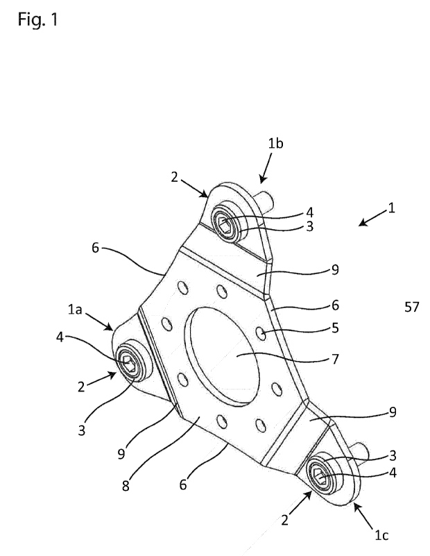
3-Point Torque Support
FIG. 1 shows a three-dimensional oblique view of an example of a torque
support 1
according to the invention. Fig. 2 is a top view of the torque support 1 of
FIG. 1. FIG. 3 is a
cross-sectional view of the torque support 1 of FIG. 1 and FIG. 2. The same
reference numerals
designate correspondingly identical parts/features in FIGS. 1 to 3.
Referring to FIGS. 1 to 3, the torque support 1 has a base plate 8 with an
axle opening 7.
The base plate 8 in turn has three legs 1 a, 1 b, 1 c, which are arranged
around the axle opening
7. The ends of the three legs 1 a, 1 b, 1 c each point outward from the center
M of the torque
support 1. These ends are thus also the distal ends of the base plate 8. These
ends may be
provided rounded. However, this property does not change the fact that the
base plate 8 can be
designated as triangular in plan view, even if it has no hard corners or a
waist (see later).
Furthermore, the base plate has the three sides 6 of the base plate 8.
The base plate 8 may be made of a metal, preferably a torsionally rigid hard
metal.
Thereby, the base plate 8 can be cut and metal formed for the production, for
example, by the
laser cutting method. Alternatively, however, the base plate 8 may also be
made of a plastic.
The axle opening 7 serves for the passage of a drive axle 15 (cf. FIG. 4 and
FIG. 5) or
drive shaft of an accessory of a biomass heating system, for example the drive
shaft of a screw
conveyor for biogenic fuel or the drive shaft of a rotary valve through the
torque support 1.
Optionally, the axle opening 7 may be provided for a rotatable mounting of the
drive axle.
The base plate 8 has holes 5 or bores 5 for rigid connection to a drive 13
(shown in FIG.
4 and FIG. 5). The holes 5 can be arranged on a circular line around the axle
opening 7 at regular
-9-
CA 03191425 2023- 3- 1
intervals. Alternatively, however, the holes 5 can also be arranged
differently depending on the
requirements of the drive to be fastened (and, for example, according to the
position of its
fastening holes or screw holes).
In the plan view of FIG. 2, the base plate 8 can now be referred to as a
roughly triangular
or triangular plate 8. In this case, the base plate 8 (with the exception of
the holes 5) has three
axes of symmetry, which are both the central perpendicular and the lateral
bisectors. These three
axes of symmetry with respect to the outer contour of the base plate 8 extend
through the center
M and in each case through the center of the respective leg 1 a, 1 b, 1 c.
The three legs 1 a, 1 b, 1 c extend in the distal direction and taper with the
distance to the
center M of the torque support I.
Furthermore, the base plate 8 has the three sides 6, which are formed
(optionally) as lateral
waists 6 in order to save material. The three waists 6 are thus provided on
the outer sides 6 of
the base plate 8 of the torque support 1.
The axle opening 7 may be provided at the center M of the torque support. In
this case,
the axle opening 7 is a (preferably circular) hole, the center M of which can
be the center or the
geometric center of gravity of the torque support 1.
Furthermore, the torque support 1 has three fastening points 2 for connection
to a support
structure of a device, for example to a housing of a transport device for
fuels of a biomass heating
system. These three fastening / attachment points 2 are respectively provided
at the distal ends
of the legs la, lb, lc. A 3-point torque support 1 is thus provided.
The three fastening points 2 of the three legs la, lb, lc (and thus the legs
la, lb, 1 c) each
have in detail a receiving hole 3a (shown in FIGS. 4 and 5) for an insulating
bushing 3.
The insulating bushing 3 can consist of a plastic (for example POM, PPs, PVC,
PP, PE,
PPs-el, PE-el, PVDF or rubber), which can preferably have sound-absorbing
properties. The
-10-
CA 03191425 2023- 3- 1
three insulating bushings 3 are each bush-shaped and have in their center an
opening for
(preferably form-fitting) receiving a fastening element 4, for example a screw
4 (cf. FIG. 4 and
FIG. 5).
The respective center of the three receiving holes 3a form the three comers of
a triangle
D (see the dash-dot line of FIG. 2), which is preferably formed on the same
side. The center of
gravity of this triangle D may in turn be the center M of the torque support
1.
Furthermore, the three legs 1 a, 1 b, 1 c are each designed to be bent by
means of a
(preferably double) bent or angularly arranged plate section 9. Thus, a crank
9 is provided which
enables the insulating bushings 3 to rest centrally on the legs 1 a, 1 b, 1 c
of the base plate 8 (see
in particular the left side of FIG. 3 for the shape of the crank 9). In other
words, the base plate 8
with its legs la, lb, 1 c has a bridge-shaped cross section (cf. FIG. 3), with
the legs la, lb, lc
resting on the output side or on the side of the output. This also ensures
that the insulating bushes
3 alone rest on the output side, inter alia in order to reduce the sound
transmission through the
torque support 1.
The receiving holes 3 of the base plate 8 do not lie in the same (cross-
sectional) plane as
the axle opening 7, which further improves the sound damping and also the
assembly.
It can also be seen from FIG. 3 that the torque support 1 with its receiving
holes 3 can be
set up such that the receiving holes 3 can be pushed over the insulating
bushes 3.
For example, the insulating bushings 3 can already be mounted in advance on
the output-
side housing 11, wherein then receiving holes 3 are pushed onto the insulating
bushings 3, and
wherein then the fixing can take place by means of the further fastening
elements, for example
bolts or screws (cf. also FIG. 5, wherein the insulating bushings 3 are
preassembled on the output
side, and then the torque support 1 with its receiving holes 3 is pushed onto
the insulating
bushings 3).
-1 1 -
CA 03191425 2023- 3- 1
The three insulating bushes 3 can alternatively or additionally have a stop,
so that they can
be inserted into the receiving hole 3 a until the stop of the insulating bush
3 rests on the base
plate. Then, as a result, the torque support 1 with the insulating bushes can
be screwed to the
output-side housing.
Rotary Valve with Torque Support
FIG. 4 shows an exploded view of a rotary valve with a torque support 1 of
FIGS. 1 to 3.
The torque support 1 is provided between the drive 13 and a housing 11 of a
rotary valve
10.
On the drive side, the drive 13, for example an electric motor, is provided
with a
transmission 14/ gear 14 with a receptacle for a drive axle 15 or drive shaft
15 of the rotary valve
10.
On the output side, the housing 11, a cellular wheel 12 with two chambers, a
mechanism
16 for a worm drive (not shown) and a fuel supply port 17 are provided.
The torque support 1 serves for the stable fixing / mounting of the drive 13
and the
transmission 14, which together provide a transmission motor.
In the assembled state, the axle 15 is provided guided through the torque
support 1.
The transmission 14 is connected or screwed to the torque support 1 by means
of fastening
elements 5 a, for example screws 5 a.
A counterpart to the torque support 1 is provided on the housing 11, to which
counterpart
the insulating bushings 3 are attached. The torque support 1 can be pushed
with its receiving
holes 3 a onto the insulating bushes 3, and then the torque support 1 can be
screwed to the
housing 11.
-12-
CA 03191425 2023- 3- 1
As a result or in the assembled state, the torque support 1 is attached to the
housing 11 by
means of three fastening points 2, the three fastening points 2 having the
same distance from the
center M of the axle opening 7 and being arranged in a triangularly
symmetrical manner.
In addition, the insulating bushings 3 are located in the (solid) sound
transmission path
between the housing 11 and the motor 13.
Room Discharge Device with Torque Support
FIG. 5 is an exploded view of a room discharge device 20 with a torque support
1 of FIGS.
1 to 3. Thus, it is clarified that the present torque support can be used for
various types of
transport devices for biomass heating devices. The same reference numerals as
in FIG. 4 denote
the same or similar parts/features.
The space discharge device 20 has a conveying channel 21 for a fuel, in which
(not shown)
a conveying screw is provided for conveying the fuel, the conveying screw
being driven via the
axle 15. The fuel is conveyed in FIG. 5, for example, from the right side
through the delivery
channel 21 to the left and then down through the outlet 23. The conveying
channel 21 is part of
a support structure of the space discharge device 20.
In FIG. 5, too, the torque support 1 connects the drive side to the output
side. On the output
side, a counterpart, in the present case a suspension 22 with a bearing for
the axle 15, to the
torque support 1 is provided, to which the insulating bushes 3 are attached.
Incidentally, counter
nuts for the screw connection are shown to the right of the insulating bushes.
Here too, the torque support 1 can be pushed onto the insulating bushes 3. The
insulating
bushings 3 are thus advantageously located in the (solid-state) sound
transmission path between
the fuel delivery channel 21 and the motor 13.
As a result, or in the assembled state, the torque support 1 is attached to
the conveying
channel 11 by means of three fastening points 2, the three fastening points 2
having the same
distance from the center M of the axle opening 7, and being arranged
triangularly symmetrically.
-13-
CA 03191425 2023- 3- 1
Advantages
The purpose of the torque support 1 is first of all to absorb the differential
torque of the
drive and output and to introduce it into the support structure (for example,
housing or frame).
In this case, not only the torque in the axis of the drive axle / drive shaft
is to be absorbed in the
present case, but also laterally acting torques (or also bending torques)
which can result in
particular during the transport of piece goods by means of a screw or sluice.
In this case, for
example, pellets can wedge laterally in the conveying channel 21, as a result
of which transverse
and bending forces can be produced on the torque support via the axle 15,
which forces can also
be reinforced again by the lever action of the axle 15 (depending on the
further axle bearings).
Thus, distortions can occur in different directions.
However, the suspension of the torque support 1 at three points 2 mechanically
ensures
that a high stability of the torque support 1 also exists with respect to such
twists. The three
fastening points 2 ensure that forces in all relevant directions can be
absorbed by the torque
support 1.
In the case of the conventional torque support of AT 13 782 Ul with only two
fastening
points, lateral forces which lie transversely to the connecting line of the
fastening points can be
absorbed only inadequately, for example as a result of tests. Thus, the
present torque support 1
is a support fixed or resting on three fastening points 2, wherein
conventional torque supports
for accessories or transport devices in biomass heating systems, in contrast
thereto, are 2 or 1-
point supports (i.e. with two or one fastening point).
If, however, four or more fastening points were now provided for further
increasing the
stability, the attenuation of the noises or of the sound by the torque support
deteriorates, since
more fastening points mean more contact surface, more material for the sound
conduction and
thus a lower sound resistance between the drive side and the output side.
-14-
CA 03191425 2023- 3- 1
In this respect, it has been found in the present case that three fastening
points are the ideal
compromise between mechanical stability (also in transverse directions to the
axle 15 or under
bending stress) and the sound-damping properties of the torque support 1.
In addition, the position of the fastening points 2 or of the centers of the
receiving holes 3
at the corners of an equilateral triangle contributes to increasing the
mechanical stability, as is
apparent to the person skilled in the art from mechanical/physical
considerations when
considering the triangular geometry disclosed herein. The position of the
fastening points 2 also
contributes to a simple mounting on the counterpart, since the points 2 must
necessarily lie in
one plane, and, for example, manufacturing tolerances can be compensated or
handled more
easily than, for example, in the case of a torque support with four more
fastening points.
Furthermore, the base plate is also more stable in the approximately
triangular shape or
the symmetrical shape as an equilateral triangle and easy to handle in
assembly.
Furthermore, (preferably) the noise generation or noise emission of a
transport device of
a biomass heating system is to be further reduced. The three insulating
bushings 3, which
represent a barrier in the sound conduction path between the drive 13 and the
output side, serve
for this purpose.
Here, a synergy between the three fastening points 2 and the three insulating
bushes 3
occurs: If more than three insulating bushings 3 were provided, their common
sound resistance
would decrease, which would impair the damping effect of the torque support 1.
Furthermore, a spacing of the holes 5 for the drive to the receiving holes 3 a
in the
thickness direction is also provided by means of the offset 9. This also
improves the damping
effect of the torque support 1 due to the angular configuration of the
resulting sound conduction
paths in the base plate 8 and, for example, the resulting interference between
the sound
conduction threads.
The crank 9 also serves for simple assembly of the torque support.
-15-
CA 03191425 2023- 3- 1
In the present case, it has thus been recognized that the torque support 1
plays an important
role in the transmission of the sound or noises in the device.
In this respect, the above-described design of the torque support 1 with the
insulating
bushings 3 serves to reduce or even interrupt the transmission of sound or
noise, in particular
from the drive 13 to the housing 11, while at the same time providing an
approximately optimal
mechanical stability, in particular for the above applications (cf. FIG. 4 and
FIG. 5).
In addition, it has been recognized in the present case that the disturbing
noise emissions
can also arise from the torque support itself and the fastening of a
conventional torque support
itself.
In this case, a noise can be generated by twisting a base plate (provided, for
example, as a
double angle) of the prior art under stress, a metal-on-metal noise being
generated between the
fastening elements (metal bolts or screws) and the base plate of a torque
support, since these
work on one another under stress.
The use of the insulating bushing 3 according to the invention prevents this
rubbing of
metal on metal, whereby a disturbing metal-on-metal noise can be avoided.
In addition, the present torque support is quite simple to produce and
requires
comparatively little material. With this, it is cost-saving.
The insulating bushings 3 can be produced in large numbers, for example, by
injection
molding or by deep-drawing.
In summary, a 3-point torque support (three-point bearing) with optional
integrated noise-
absorbing fastenings / attachments (the insulation bushings 3) is disclosed.
Due to its geometry,
the present torque support is particularly stable with a simple construction.
Noise generation by
the torque support itself or its contact points with other metal parts is
advantageously avoided.
-16-
CA 03191425 2023- 3- 1
Other Embodiments
The invention admits other design principles in addition to the embodiments
and aspects
explained. Thus, individual features of the various embodiments and aspects
can also be
combined with each other as desired, as long as this is apparent to the person
skilled in the art
as being executable.
Although the torque support 1 with its legs is shown approximately
symmetrically (except
for the fastening holes 5, which are arranged in each case depending on the
drive to be fastened),
the torque support 7 can also be provided asymmetrically as long as it has
three fastening points
2.
Although the torque support 1 with its base plate 8 is described in plan view
in the form
of an equilateral triangle (and the corresponding symmetry thereof), the
torque support 1 can
also be provided with other symmetries (for example an equilateral and not
equilateral triangle,
or a right-angled triangle).
Although the three legs 1 a, 1 b, 1 c are provided identically in the
embodiment, they may
differ from one another in shape and structure.
The axle opening / axle orifice 7 may also be provided offset from the center
of the torque
support 1. In this case, in particular, the center M of the hole of the axle
opening 7 can be
provided offset or displaced with respect to the geometric center of the
torque support 1.
Although the symmetry of the fastening points 2 is formed as an equilateral
triangle,
another triangle can also be selected as the basic shape, for example an
equilateral (and not
equilateral) triangle or a right-angled triangle (depending on the mechanical
requirements of the
specific application, which dictate the forces acting on the torque support
7).
Although the axle opening 7 serves for the rotatable mounting of a drive axle
for an
accessory of a biomass heating system, the axle opening 7 can also accommodate
other axes
-17-
CA 03191425 2023- 3- 1
relating to other applications. With this, the torque support 1 can also be
used differently as long
as a torque of an axle is to be supported.
A plain bearing, for example made of plastic, may optionally be provided in
the axle
opening 7.
The support structure can be any structure that allows a drive to be fastened
via a torque
support.
Depending on the application, the insulating bushes 3 may also be omitted. In
this way,
the torque support 1 can also be fastened without an insulating bushing 3.
Fuels other than wood chips or pellets can be used as fuels for the biomass
heating system.
The embodiment(s) disclosed herein are provided for description and
understanding of the
disclosed technical facts and are not intended to limit the scope of the
present disclosure.
Therefore, this should be construed to mean that the scope of the present
disclosure includes any
modification or other various embodiments based on the technical spirit of the
present
disclosure.
-18-
CA 03191425 2023- 3- 1
List of Reference Numerals
1 torque support
la, lb, lc legs
2 mounting points of the torque support
3 Insulation bushing
3 a receiving hole for the plastic bushing
4 fastening element / metal bolt / screw
5 mounting holes for the drive
5a mounting elements / mounting bolts / mounting screws for the
drive
6 pages / waists
7 axle opening
8 base plate
9 crank
10 Rotary valve
11 housing of the rotary valve
12 cellular wheel
13 drive
14 transmission
15 shaft / axle / axis
16 mechanism for worm drive (not shown)
17 fuel supply port! opening
20 room discharge device
21 fuel delivery channel
22 torque support suspension
23 outlet for the fuel
-19-
CA 03191425 2023- 3- 1