Note: Descriptions are shown in the official language in which they were submitted.
90327767
1
DESCRIPTION
INFORMATION STORAGE DEVICE, REMOVABLE DEVICE, DEVELOPER
CONTAINER, AND IMAGE FORMING APPARATUS
This application is a divisional of Canadian Patent
Application No. 3074231, which is a divisional of Canadian Patent
Application No. 2972759, which in turn is a divisional of Canadian
Patent Application No. 2782610 filed on 13 June 2011.
TECHNICAL FIELD
The present invention relates to an image forming apparatus
such as a copying machine, a printer, a facsimile, or a multi-
function peripheral (MFP), a removable device and a developer
container that are removably installed therein, and an information
storage device installed therein.
BACKGROUND ART
Conventionally, in an image forming apparatus such as a
copying machine, a technique of removably installing a removable
device such as a developer container (a toner bottle, a toner
storage container, or an ink cartridge) or a process cartridge on
an image forming apparatus body has been usually used (for example,
Patent Literature 1: Japanese Patent Application Laid-open No.
200969417, Patent Literature 2: Japanese Patent Application Laid-
open No. 2006-209060, and Patent Literature 3: Japanese Patent
Application Laid-open No. 2002-196629).
In the removable device, an information storage device (an
information recording unit or a non-volatile memory) such as an ID
chip storing information to be exchanged with the image forming
apparatus body is installed. In a state in which the removable
device is set to the image forming apparatus body, information (for
example, information such as manufacturing year, month, and date of
the removable device, a manufacturing lot number, or a color of
toner, or a kind of toner) stored in the information storage device
Date Recue/Date Received 2023-03-03
2
is transmitted to a control unit of the image forming =
apparatus body, or information (information such as a use
history of the image forming apparatus) is transmitted from
the image forming apparatus body to the information storage
device, so that fulfilling quality control of the image
forming apparatus body and the removable device is
performed.
Patent Literature 1 discloses a contact-type
information storage device (an information recording unit).
Specifically, in the contact-type information storage
device (an ID chip), when the removable device (a toner
storage container) is set to the image forming apparatus
body, a metal pad (a terminal) comes in contact with a body
side terminal of a connector installed in the image forming
apparatus body. As a result, information can be exchanged
between the information storage device of the removable
device and the control unit (the body side information
recording unit) of the image forming apparatus.
Further, a feeding opening for allowing the stored
toner to flow out to the outside is installed in the
developer container. The opening needs remain closed until
it is loaded onto a developing device so as to prevent the
toner from being scattered or leaking.
As a configuration for achieving the above desire,
there has been suggested a configuration in which a shutter
for opening/closing the opening installed in the developer
container is installed. Further, as a configuration of the
shutter, there has been suggested a configuration in which
a flat plate-like shutter that is movable in a direction
traversing the toner and an outlet is installed (For
example, Patent Literature 4: Japanese Patent Application
Laidopen No. 2010-066638).
However, the conventional techniques described above
Date Recue/Date Received 2023-03-03
N
3
have the following problems.
As a first problem, the conventional contact-type
information storage device may electrically get damaged
since an electric circuit of the information storage device
is not sufficiently earthed and so becomes an electrically
floating state when the removable device is attached to or
removed from the device body.
The present invention is made to solve the first
problem described above and provides an information storage
device, a removable device, a developer container, and an
image forming apparatus in which electrical damage is
difficult to occur in the information storage device even
when the contact-type information storage device is
installed in the removable device removably installed in
the image forming apparatus body.
As a second problem, in the conventional contact-type
information storage device, there may occur a problem in
that contact sections thereof are misaligned (a contact
failure) due to wrong positioning of the terminal (metal
pad) installed in the information storage device and the
terminal of the image forming apparatus body. Particularly,
when-the terminal of the information storage device is
small, the problem becomes important.
The present invention is made to solve the second
problem described above and provides a removable device, a
developer container, and an image forming apparatus in
which a contact failure caused by a positioning failure
with the body side terminal of the connector of the image
forming apparatus body is difficult to occur even when the
contact-type information storage device is installed in the
removable device removably installed in the image forming
apparatus body.
A third problem is as follows. In recent years, toner
Date Recue/Date Received 2023-03-03
//
4
having a small particle diameter has been used so as to
improve the resolution. Improving a filter function so as
to cope with using the toner may increase the material or
processing cost. That is, when a foamable material is used,
it is necessary to prescribe mesh fineness that does not
let the toner through, a so-call foaming degree, but as
mesh fineness increases, flexibility tends to decrease.
This tendency may be difficult to go along with movement of
the shutter, and a sealing characteristic may get worse.
. The present invention has an improved invention of a
shutter mechanism of the conventional toner feeding device.
The improved invention provides a developer storage
container and an image forming apparatus which have a
configuration capable of reliably preventing the toner from
leaking from the developer storage container that is
replaced by an attaching/detaching operation at a low cost.
DISCLOSURE OF INVENTION
In the present invention, a "process cartridge" is
defined as a removable device that is configured such that
at least one of a charging unit for charging an image
carrier, a developing unit (a developing device) for
developing a latent image formed on the image carrier, and
a cleaning unit for cleaning the surface of the image
carrier is integrally formed with the image carrier and
that is installed removably on the image forming apparatus
body.
Further, in the present invention, a "nearly
rectangular metallic plate" is defined to include a nearly
rectangular one as well as a rectangular one. Thus, one in
which all or part of an angular section of the rectangular
metallic plate is chamfered and an R-shaped one are also
included in the "nearly rectangular metallic plate."
Date Recue/Date Received 2023-03-03
5
//
4111
' The effect of the present invention on the first
problem is as follows. The present invention can provide
an information storage device, a removable device, a
developer container, and an image forming apparatus in
5 which electrical damage is difficult to occur in the
information storage device even when the contact-type
information storage device is installed in the removable
device removably installed on the image forming apparatus
body since an earth terminal engaged with a body side earth
terminal formed in a protruding section of the image
forming apparatus body is formed in a hole or a notch
formed in a substrate of the information storage device.
The effect of the present invention on the second
problem is as follows. In the present invention, the
contact-type information storage device is held On a
holding section to be movable on a virtual plane that is
substantially orthogonal to a movement direction in which a
terminal approaches and comes in contact with a body side
terminal. Thus, the present invention can provide a
removable device, a developer container, and an image
forming apparatus in which a contact failure caused by a
positioning failure with the body side terminal of the
connector of the image forming apparatus body is difficult
to occur even when the contact-type information storage
device is installed in the removable device removably
installed in the Image forming apparatus body.
The effect of the present invention on the third
problem is as follows. According to the present invention,
by causing riding-up when hitting against a rib disposed on
a circumferential edge of an ejecting opening, adhesion can
= be secured.
Thus, by using a shutter that is an existing component
used for opening/closing the ejecting opening, a toner leak
Date Recue/Date Received 2023-03-03
90327767
6
from the ejecting opening can be reliably prevented without
adding a special structure.
Another aspect of the invention relates to a toner container
that is attachable to and detachable from an image forming
apparatus body, the toner container comprising: a container body
to contain toner; an opening at one end of the container body; a
cover that covers the opening of the container body; a toner
discharge port to discharge the toner in the container body, and
the toner discharge port is formed at a lower side of the cover;
a shutter that is attached to the cover, and the shutter includes
a main shutter that covers the toner discharge port, the main
shutter is movable between a closed position to close the toner
discharge port and an open position to open the toner discharge
port in conjunction with an attaching/detaching operation of the
toner container to/from the image forming apparatus body; a
cylindrical structure that is provided in the cover and into
which a protrusion of the image forming apparatus body is
insertable; protrusions that are provided on both sides of the
cover, and the protrusions protrude in a direction that is
orthogonal to a mounting direction of the toner container; and an
identifier that is provided on the cover to indicate a color of
the toner in the container body, wherein a leading end of the
cylindrical structure is provided downstream of leading ends of
the protrusions in the mounting direction of the toner container,
a leading end of the main shutter is provided downstream of the
leading ends of the protrusions in the mounting direction of the
toner container in a state where the main shutter is in the
closed position, and the protrusions are provided downstream of
the identifier in the mounting direction of the toner container.
Date Recue/Date Received 2023-03-03
90327767
6a
Another aspect of the invention relates to a toner container
that is attachable to and detachable from an image forming
apparatus body, the toner container comprising: a container body
to contain toner; an opening at one end of the container body; a
cover that covers the opening of the container body; a
cylindrical structure that is provided in the cover and into
which a protrusion of the image forming apparatus body is
insertable; and a pair of protrusions, each protrusion of the
pair of protrusions being provided on a respective side of the
cover, and each protrusion of the pair of protrusions protrudes
orthogonal to a mounting direction of the toner container,
wherein a leading end of the cylindrical structure is provided
downstream of leading ends of the pair of protrusions in the
mounting direction of the toner container.
Another aspect of the invention relates to a toner container
that is attachable to and detachable from an image forming
apparatus body, the toner container comprising: a container body
to contain toner; a first opening at one end of the container
body; a cover that covers the first opening of the container
body; a toner discharge port to discharge the toner in the
container body, and the toner discharge port is formed at a lower
side of the cover; a shutter that is attached to the cover, that
covers the toner discharge port, the shutter is movable between a
closed position to close the toner discharge port and an open
position to open the toner discharge port in conjunction with an
attaching/detaching operation of the toner container to/from the
image forming apparatus body; a second opening that is provided
in the cover and into which a protrusion of the image forming
apparatus body is insertable; a protrusion that is provided on a
side of the cover, and the protrusion protrudes in a direction
that is orthogonal to a mounting direction of the toner
Date Recue/Date Received 2023-03-03
90327767
6b
container; and an identifier that is provided on the cover to be
different depending on a color of the toner in the container
body, wherein a leading end of the second opening is provided
downstream of a leading end of the protrusion of the cover in the
mounting direction of the toner container, an edge of the shutter
is provided downstream of the leading end of the protrusion of
the cover in the mounting direction of the toner container in a
state where the shutter is in the closed position, and the
protrusion of the cover is provided downstream of the identifier
in the mounting direction of the toner container.
BRIEF DESCRIPTION OF DRAWINGS
Fig. 1 is an overall configuration view illustrating an
image forming apparatus according to an embodiment;
Fig. 2 is a cross sectional view illustrating an image
forming unit;
Fig. 3 is a schematic view illustrating a state in which a
toner container is installed in a toner feeding device;
Fig. 4 is a schematic perspective view illustrating a state
in which four toner containers are installed in a toner container
storage unit;
Fig. 5 is a schematic perspective view illustrating a state
in which one toner container is installed in a toner container
storage unit;
Fig. 6 is a side view illustrating a state in which a toner
container is installed in a toner container storage unit;
Fig. 7 is a cross sectional view illustrating a state in
which a cap section is installed in a cap receiving section;
Date Recue/Date Received 2023-03-03
90327767
6c
Fig. 8 is a perspective view illustrating a cap receiving
section of a toner container storage unit;
Fig. 9 is an enlarged perspective view illustrating a
neighborhood of a leading end section of a bottle receiving
section;
Fig. 10 is a back view illustrating a state in which a cap
section is set to a bottle receiving section in a regular 20
toner container;
Fig. 11 is a back view illustrating a state in which a cap
section is set to a bottle receiving section in a non-
Date Recue/Date Received 2023-03-03
/II!
7
regular toner container;
Fig. 12 is a perspective view illustrating a cap
receiving section to which a cap section is set;
Fig. 13 is a front view illustrating a cap receiving
section in a state in which a cap section is set;
Fig. 14A is a back view illustrating a cap receiving
section, and Fig. 14B is a partial enlarged view
illustrating a neighborhood of a contacted groove encircled
by a dotted line in a cap receiving section of Fig. 14A;
Fig. 15 is a perspective view illustrating a cap
receiving section from obliquely below;
Fig. 16 is a perspective view illustrating a
connector;
Fig. 17 is a schematic view illustrating a state in
which an information storage device of a cap section is set
to a connector of a cap receiving section;
Fig, 18 is a perspective view illustrating a toner
container from obliquely below;
Fig, 19 is a side view illustrating a toner container;
Fig. 20 is a perspective view illustrating a cap
section side of a toner container from obliquely below;
Fig, 21 is a front view illustrating a toner container
from a cap section side;
Fig. 22 is a perspective view illustrating a state in
which a shutter member of a toner container closes a toner
discharge opening;
Fig, 23 is a perspective view illustrating a state in
which a shutter member of a toner container opens a toner
discharge opening;
Figs, 24A to 24C are schematic views illustrating an
opening operation of a shutter member that is in
conjunction with a mounting operation of a toner container
on a toner container storage unit;
Date Recue/Date Received 2023-03-03
8
Fig. 25 is a perspective view illustrating a shutter
member;
Fig. 26 is another perspective view illustrating a
shutter member;
Fig. 27 is a perspective view illustrating a state in
which an information storage device is extracted;
Fig. 28 is a six-plane view illustrating a holding
member of an information storage device;
Fig. 29 is a three-plane view illustrating an
information storage device;
Fig. 30 is a cross sectional view illustrating a
neighborhood of a cap section of a toner container;
Fig. 31 is a schematic cross sectional view
illustrating a toner container according to a second
embodiment;
Fig. 32 is a back view illustrating a cap section in
the toner container of Fig. 31;
Fig, 33 is a perspective view illustrating a holding
cover engaged with a holding member;
Fig, 34 is a schematic view illustrating a state in
which an information storage device of a toner container
according to a third embodiment is set to a connector of a
cap receiving section;
Fig, 35 is a three-plane view illustrating a substrate
of an information storage device according to a fourth
embodiment;
Fig. 36 is a three-plane view illustrating a substrate
of an information storage device according to a fifth
embodiment;
Fig. 37 is a perspective view illustrating an
information storage device, a holding member, and a
connector;
Fig. 38 is a perspective view illustrating a state in
Date Recue/Date Received 2023-03-03
9
which an information storage device is engaged with a .
connector;
Figs. 39A and 398 are schematic views illustrating an
electric circuit of an information storage device and an
electric circuit of a connector;
Figs. 40A and 408 are front views illustrating an
information storage device;
Fig. 41 is a view illustrating an information storage
device in an inspection process;
Figs. 42A and 428 are perspective views illustrating a
toner container according to a sixth embodiment;
Fig. 43 is a front view illustrating a toner container
in which a face plate is not installed;
Fig. 44 is a cross sectional view illustrating a toner
container in which an information storage device and a face
plate are installed;
Fig. 45 is a view illustrating a state in which an
information storage device is being inserted into a
connector;
Figs. 46A and 463 are perspective views illustrating a
toner container of another form;
Figs. 47A to 47C are views illustrating a toner
container of another form:
Fig. 48 is an exploded perspective view illustrating a
toner container according to a seventh embodiment;
Fig. 49 is a cross sectional view illustrating the
toner container of Fig. 48;
Fig. 50 is a perspective view illustrating an image
forming apparatus according to an eighth embodiment;
Figs. 51A and 51B illustrate toner cartridges
installed in the image forming apparatus of Fig. 50, Fig.
51A is a cross sectional view, and Fig. 51B is a bottom
view;
Date Recue/Date Received 2023-03-03
10
Fig. 52 is a perspective view illustrating an image
forming apparatus according to a ninth embodiment;
Fig. 53 is a schematic view illustrating a state in
which a connector is connected to an information storage
device in the image forming apparatus of Fig. 52;
Fig. 54 is a perspective view illustrating an ink
cartridge according a tenth embodiment;
Fig. 55 is a top view illustrating an image forming
apparatus in which the ink cartridge of Fig. 54 is
installed;
. Fig. 56 is a perspective view illustrating a connector
of an image forming apparatus according to the tenth
embodiment;
Fig. 57 is a three-plan view illustrating an
information storage device that comes in contact with the
connector of Fig. 56;
Fig. 58 is a three-plane view illustrating an
information storage device of another form;
Fig. 59 is a perspective view illustrating a toner
container according to a twelfth embodiment;
Fig. 60 is an enlarged perspective view illustrating
configurations of an information storage device and a
holding member according to the twelfth embodiment;
Fig. 61 is an exploded perspective view illustrating
the configurations of the information storage device and
the holding member according to the twelfth embodiment;
Fig. 62 is an enlarged perspective view illustrating a
fixing state between the information storage device and the
holding member according to the twelfth embodiment;
Fig. 63 is an enlarged perspective view illustrating a
fixing state between an information storage device and a
holding member according to a thirteenth embodiment;
Fig. 64 is an enlarged perspective view illustrating
Date Recue/Date Received 2023-03-03
11
configurations of the information storage device and the
holding member according to the thirteenth embodiment;
Fig. 65 an enlarged perspective view illustrating a
fixing state between an information storage device and a
holding member according to a fourteenth embodiment;
Fig. 66 is an enlarged perspective view illustrating
configurations of the information storage device and the
holding member according to the fourteenth embodiment;
Fig. 67 is a cross sectional view illustrating a cap
section illustrated in Fig. 18;
Fig. 68 is a perspective view, viewed from a bottom
surface of a shutter, for explaining a configuration of a
shutter used in a cap section illustrated in Fig. 18;
Figs. 69A and 69B are views, corresponding to Fig. 18,
for explaining an opening/closing state of a shutter
illustrated in Figs. 69A and 69B;
Figs. 70A to 70C are views for explaining a
configuration of the shutter illustrated in Figs. 69A and
69B;
Figs. 71A to 71C are views illustrating an opening
state of the shutter illustrated in Figs. 70A to 70C and a
cross section of the state;
Fig. 72 is a plane view for explaining a relation
between a body side shutter closing mechanism and a
shutter;
Fig. 73 is a plane view illustrating a state of the
body side shutter closing mechanism illustrated in Fig. 72;
Fig. 74 is a plane view illustrating a state of the
body side shutter closing mechanism that has changed from
the state illustrated in Fig. 73;
Figs. 75A to 751D are views for explaining a positional
relation between a toner discharge opening and a shutter
and a sealing state of a seal material;
Date Recue/Date Received 2023-03-03
=
12
Figs. 76A and 76B are views illustrating a
configuration of an information storage device used in a
sixteenth embodiment;
= Fig. 77 is a perspective view of a cap receiving side
that becomes part of an electrical connection section with
an information storage device;
Fig. 78 is a perspective view illustrating a common
electronic substrate including a shutter connected with an
information storage device;
Fig. 79 is a view for explaining a connection state
between the information storage device used in the
sixteenth embodiment and a connector at a cap receiving
section side;
Fig. 80 is a perspective view, viewed from a front
right side in an insertion direction of a cap in the state
in which a shutter is closed, for'explaining a modification
related to a configuration of a cap section according to a
seventeenth embodiment;
Fig. 81 is a perspective view viewed from a front left
side in an insertion direction of the cap illustrated in
Fig. BO;
Fig. 82 is an exploded perspective view of the cap
section illustrated in Fig. 80;
Fig, 83 is a perspective view illustrating a
modification of a main part of the cap section illustrated
in Fig. 80;
Fig. 84 is a plane view for explaining an aspect of a
body side shutter closing mechanism targeting on the cap
section illustrated in Fig. 80;
Fig. 85 is a plane view illustrating the body side =
shutter closing mechanism illustrated in Fig. 84;
Fig. 86 is a plane view illustrating a state of the
body side shutter closing mechanism that has changed from
Date Recue/Date Received 2023-03-03
13
the state illustrated in Fig. 85;
Fig. 87 is a three-plane view illustrating an
alternative of the substrate illustrated in Fig. 36; and
Figs. BBA to 88C are plane views illustrating further
alternatives of the substrate illustrated in Fig. 36.
BEST MODE(S) FOR CARRYING OUT THE INVENTION
Hereinafter, embodiments of the present invention will
be described in detail with reference to the accompanying
drawings. In the drawings, the same or corresponding parts
are denoted by the same reference numerals, and thus a
duplicated description thereof will be appropriately
simplified or omitted.
First Embodiment
A first embodiment of the present invention will be
described in detail with reference to Figs. 1 to 30.
First, a configuration and operation of the entire
image forming apparatus will be described.
As illustrated in Fig. 1, in a toner container storage
unit 70 above an image forming apparatus body 100, toner
containers 32Y, 32M, 32C, and 32K (developer containers)
are removably (replaceably) installed as four removable
devices corresponding to respective colors (yellow, magenta,
cyan, and black) (also see Figs. 3 to 5).
An intermediate transfer unit 15 is disposed below the
toner container storage unit 70. Image forming units 6Y,
6M, 6C, and 6K corresponding to respective colors (yellow,
magenta, cyan, and black) are disposed in line to face an
intermediate transfer belt 8 of the intermediate transfer
unit 15.
Toner feeding devices 60Y, 60M, 60C, and 60K are
disposed below the toner containers 32Y, 324, 32C, and 32K
Date Recue/Date Received 2023-03-03
14
as the removable devices (developer containers),
respectively. The toners stored in the toner containers
32Y, 32M, 32C, and 32K are supplied (fed) to the inside of
the developing devices of the image forming units 6Y, 6M,
6C, and 6K by the toner feeding devices 60Y, 60M, 60C, and
60K, respectively.
Referring to Fig. 2, the image forming unit 6Y
corresponding to yellow includes a photosensitive drum IY,
a charging unit 4Y disposed around the photosensitive drum
IY, a developing device 5Y (a developing section), a
cleaning unit 2Y, a neutralizing unit (not shown), or the
like. An image forming process (a charging process, an
exposure process, a developing process, a transfer process,
and a cleaning process) is performed on the photosensitive
drum 1Y, and so a yellow image is formed on the
photosensitive drum IY.
The remaining three image forming units 6M, 6C, and 6K
have almost the same configuration as the image forming
unit 6Y corresponding to yellow except that colors of used
toner are different. Hereinafter, a description of the
remaining three image forming units 6M, 6C, and 6K will be
appropriately omitted, and a description will be made in
connection with the image forming unit 6Y corresponding to
yellow.
Referring to Fig. 2, the photosensitive drum lY is
rotationally driven clockwise in Fig. 2 by a driving motor
(not shown). The surface of the photosensitive drum lY is
uniformly charged at the position of the charging unit 4Y
(the charging process).
Thereafter, the surface of the photosensitive drum lY
reaches an irradiation position of laser light L emitted
from an exposure unit 7 (see Fig. 1), and an electrostatic
latent image corresponding to yellow is formed by exposure
Date Recue/Date Received 2023-03-03
15
scanning at this position (the exposure process).
Then, the surface of the photosensitive drum lY
reaches the position facing the developing device 5Y, and
the electrostatic latent image is developed at this
position, so that a yellow toner image is formed (the
developing process).
Next, the surface of the photosensitive drum lY
reaches the position facing the intermediate transfer belt
8 and a primary transfer bias roller 9Y, and the toner
image on the photosensitive drum lY is transferred onto the
intermediate transfer belt 8 at this position (a primary
transfer process). At this time, a slight amount of non
transfer toner remains on the photosensitive drum IY.
Thereafter, the surface of the photosensitive drum lY
reaches the position facing the cleaning unit 2Y, and the
non-transfer toner remaining on the photosensitive drum lY
is mechanically collected by a cleaning blade 2a at this
position (the cleaning process).
Finally, the surface of the photosensitive drum lY
reaches the position facing the neutralizing unit (not
shown), and residual potential on the photosensitive drum
lY is removed at this position.
Thus, a series of image forming processes performed on
the photosensitive drum lY are finished,
The above described image forming process is performed
even in the other image forming units 6M, 6C, and 6K in the
same manner as in the yellow image forming unit 6y, That
is, the laser light L based on image information is
irradiated from the exposure unit 7 disposed below the
image forming units onto the photosensitive drums of the
image forming units 6M, 6C, and 6K. Specifically, the
exposure unit 7 emits the laser light L from a light source
and irradiates the laser light L onto the photosensitive
Date Recue/Date Received 2023-03-03
16
drum through a plurality of optical elements while scanning
the laser light L by a polygon mirror that is rotationally
driven.
Thereafter, toner images of respective colors formed
on the respective photosensitive drums through the
developing process are transferred onto the intermediate
transfer belt 8 in a superimposed manner. As a result, a
color image is formed on the intermediate transfer belt 8.
Referring to Fig. 1, the intermediate transfer unit 15
includes the intermediate transfer belt 8, four primary
transfer bias rollers 9Y, 9M, 9C, and 9K, a secondary
transfer bias roller 12, a plurality of tension rollers, an
intermediate transfer cleaning unit, and the like. The
intermediate transfer belt 8 is stretched over and
supported by a plurality of roller members and endlessly
moves in a direction of an arrow in Fig. 1 as one roller
member 12 is rotationally driven.
The four primary transfer bias rollers 9Y, 9M, 9C, and
9K sandwich the intermediate transfer belt 8 together with
the photosensitive drums 1Y, 1M, 1C, and 1K, respectively,
to form primary transfer nips. A transfer bias reverse to
a polarity of the toner is applied to the primary transfer
bias rollers 9Y, 9M, 9C, and 9K.
The intermediate transfer belt 8 moves in a direction
of an arrow and sequentially passes through the primary
transfer nips of the primary transfer bias rollers 9Y, 9M,
9C, and 9K. The toner images of respective colors on the
photosensitive drums 1Y, 1M, 1C, and IK are primary-
transferred onto the intermediate transfer belt 8 in a
superimposed manner.
Thereafter, the intermediate transfer belt 8 onto
which the toner images of respective colors are transferred
in a superimposed manner reaches the position facing a
Date Recue/Date Received 2023-03-03
17
secondary transfer roller 19. At this position, the
secondary transfer bias roller 12 sandwiches the
intermediate transfer belt 8 together with the secondary
transfer roller 19 to form a secondary transfer nip. The
toner images of four colors formed on the intermediate
transfer belt 8 are transferred onto a recording medium P
such as a transfer sheet conveyed to the position of the
secondary transfer nip. At this time, the non-transfer
toner that has not been transferred onto the recording
medium P remains on the intermediate transfer belt 8.
Thereafter, the intermediate transfer belt 8 reaches
the position of the intermediate transfer cleaning unit
(not shown). At this position, the non-transfer toner on
the intermediate transfer belt 8 is collected.
As a result, a series of transfer processes performed
on the intermediate transfer belt 8 are finished.
The recording medium P conveyed to the position of the
secondary transfer nip is conveyed through a paper feeding
roller 27, a pair of resist rollers 28, and the like from a
paper feeding unit 26 disposed below the apparatus body 100.
Specifically, a plurality of recording media P such as
transfer sheets are stored in a superimposed manner in the
paper feeding unit 26. If the paper feeding roller 27 is
rotationally driven counterclockwise in Fig. 1, the top
recording medium P is fed toward between the rollers of the
pair of resist rollers 28.
The recording medium P fed to the pair of resist
rollers 28 stops at the position of a roller nip of the
pair of resist rollers 28 that has stopped rotational
driving. In synchronization with timing of the color image
on the intermediate transfer belt 8, the pair of resist
rollers 28 is rotationally driven, and the recording medium
P is conveyed toward the secondary transfer nip. Thus, a
Date Recue/Date Received 2023-03-03
18
desired color image is transferred onto the recording
medium P.
Thereafter, the recording medium P onto which the
color image has been transferred at the position of the
secondary transfer nip is conveyed to the position of a
fixing device 20. At this position, the color image
transferred onto the surface is fixed to the recording
medium P by heat and pressure by a fixing belt and a
pressing roller.
Thereafter, the recording medium P passes through
between rollers of a pair of ejecting rollers 29 and then
is ejected to the outside of the apparatus. A recording
medium P ejected to the outside of the apparatus by the
pair of ejecting rollers 29 is sequentially stacked on a
stack unit 30 as an output image.
Thus, in the image forming apparatus, a series of
image forming processes are finished.
Next, a configuration and operation of the developing
device in the image forming unit will be described in
further detail with reference to Fig. 2.
The developing device 51 includes a developing roller'
511 facing the photosensitive drum IY, a doctor blade 52Y
facing the developing roller 51Y, two conveying screws
disposed in developer storage units 531 and 54Y, a density
detecting sensor 561 for detecting the density of the toner
contained in the developer, and the like. The developing
roller 511 is configured with a magnet fixedly disposed to
the inside thereof, a sleeve rotating around the magnet,
and the like. A two-component developer G composed of a
carrier and a toner is stored in the developer storage
units- 531 and 541. The developer storage unit 541 is
communicated with a toner falling conveying path 641
through an opening formed thereabove.
Date Recue/Date Received 2023-03-03
19
The developing device 51 having the above described
configuration operates as follows.
The sleeve of the developing roller 51Y rotates in a
direction of an arrow in Fig. 2. The developer G supported
on the developing roller 511 by a magnetic field formed by
the magnet moves on the developing roller 511 as the sleeve
rotates.
The developer G inside the developing device 5Y is
adjusted so that a ratio of toner (toner density) contained
in the developer can be within a predetermined range.
Specifically, as the toner inside the developing device 51
is consumed, the toner stored in the toner container 32Y is
fed to the inside of the developer storage unit 54Y through
the toner feeding device 60Y (for example, see Fig. 3). A
configuration and operation of the toner feeding device
will be described later in detail.
Thereafter, the toner fed to the inside of the
developer storage unit 54Y circulates through the two
developer storage units 53Y and 541 while being mixed and
agitated together with the developer G by the two conveying
screws 55Y (movement in a direction vertical to a paper
plane of Fig. 2). The toner in the developer G is absorbed
into the carrier by frictional electrification with the
carrier and supported on the developing roller 511 together
with the carrier by magnetic force formed on the developing
roller 511.
The developer G supported on the developing roller 51Y
is conveyed in a direction of an arrow in Fig. 2 and then
reaches the position of the doctor blade 521. The
developer G on the developing roller 511 is adjusted to an
appropriate developer amount at this position and then
conveyed up to the position (a developing area) facing the
photosensitive drum 11. The toner is absorbed into a
Date Recue/Date Received 2023-03-03
20
latent image formed on the photosensitive drum lY by a
magnetic field formed on the developing area. Thereafter,
as the sleeve rotates, the developer G remaining on the
developing roller 511 reaches above the developer storage
unit 531 and leaves the developing roller 51Y at this
position.
Next, the toner feeding devices 601, 60M, 60C, and 60K
will be described in detail with reference to Figs. 3 to 5.
Referring to Fig. 3, the toners inside the toner
containers 321, 32M, 32C, and 32K installed in the toner
container storage unit 70 of the apparatus body 100 are
appropriately fed to the inside of the developing devices
by the toner feeding devices 60Y, 601'1, 60C, and 60K
respectively installed for toner colors as the toners
inside the developing devices of respective colors are
consumed.
The four toner feeding devices 60Y, 6011, 60C, and 60K
and the toner containers 321, 32M, 32C, and 32K (the
developer containers) have almost the same configuration
except that the toner colors used in the image forming
process are different. Thus, a description will be made
focusing on the toner feeding devices 601 and the toner
container 32Y corresponding to yellow, and a description of
the toner feeding devices 6011, 60C, and 60K and the toner
containers 32M, 32C, and 32K corresponding to the remaining
three colors will be appropriately omitted.
Referring to Fig. 1, if a body cover (not shown)
installed on the front side of the apparatus body 100 (the
front side in a direction vertical to the paper plane in
Fig. 1) is opened, the toner container storage unit 70 (an
insertion opening 71) is exposed. In the state in which a
longitudinal direction of the toner containers 321, 3211,
32C, and 32K (the developer containers) is a horizontal
Date Recue/Date Received 2023-03-03
21
direction., performed is an attaching/detaching operation of
the toner containers 32Y, 32M, 32C, and 32K to/from the
front side of the apparatus body 100 (an
attaching/detaching operation in which the longitudinal
direction of the toner container is an attaching/detaching
direction).
As illustrated in Fig. 4, when the toner containers
32Y, 32M, 32C, and 32K are mounted on the toner container
storage unit 70 of the apparatus body 100 (movement in a
direction of an arrow Q), in conjunction with the mounting
operation, a shutter member 34d of the toner containers 32Y,
32M, 32C, and 32K moves, and so a toner discharge opening W
(a discharging opening) is opened, so that toner feeding
openings 73w (for example, see Fig. 3) of the toner feeding
devices 60Y, 60M, 60C, and 60K are communicated with the
toner discharge opening W. The toner stored in the toner
containers 32Y, 32M, 32C, and 32K is discharged from the
toner discharge opening W and stored in a toner tank unit
61Y through the toner feeding opening 73w of the toner
feeding devices 60Y, 60M, 60C, and 60K.
Referring to the schematic view of Fig. 3, the toner
container 32Y includes a cap section 34Y that is a nearly
cylindrical-shaped toner bottle and is usually non-
rotatably held on the toner container storage unit 70 and a
container body 331(a bottle body) in which a gear 33c is
integrally formed. The container body 33Y is relatively
rotatably held on the cap section 34Y and is rotationally
driven in a direction of an arrow in Fig. 3 by a driving
unit 91 (including a driving motor, a driving gear 81, and
the like). As the container body 331 rotates, the toner
stored inside the toner container 321 (the container body
331) is conveyed in a longitudinal direction (conveyance
from the left to the right in Fig. 3) by a protrusion 33b
Date Recue/Date Received 2023-03-03
22
formed on an inner peripheral surface of the container body
33? in a helical form, and the toner is discharged from the
toner discharge opening W of the cap section 34Y. That is,
as the container body 33? of the toner container 32Y is
appropriately rotationally driven by the driving unit 91,
the toner is appropriately supplied to the toner tank unit
61Y. Further, when each of the toner containers 32Y, 32M,
32C, and 32K reaches the end of its life (when the stored
toner is almost consumed and becomes empty), it is replaced
with a new one.
Referring to Fig. 3, the toner feeding devices 60Y,
60M, 60C, and 60K include the toner container storage unit
70, the toner tank unit 61Y, a toner conveying screw 62Y,
an agitating member 65Y, a toner end sensor 66Y, the
driving unit 91, and the like.
The toner tank unit 61? is disposed below the toner
discharge opening W of the toner container 32? and stores
the toner discharged from the toner discharge opening W of
the toner container 32Y. The bottom of the toner tank unit
61Y is connected with an upstream section of the toner
conveying screw 62Y.
The toner end sensor 66Y that detects that the toner
stored in the toner tank unit 61? has become smaller than a
predetermined amount is installed on the wall surface of
the toner tank unit 61Y (at the position of a predetermined
height from the bottom). A piezoelectric sensor or the
like may be used as the toner end sensor 66Y. When the
control unit 90 detects that the toner stored in the toner
tank unit 61? has become smaller than a predetermined
amount (toner end detection) through the toner end sensor
66Y, the driving unit 91 rotationally drives the container
body 33? the toner container 32? during a predetermined
time under control of the control unit 90, so that the
Date Recue/Date Received 2023-03-03
23
toner is fed to the toner tank unit 61Y. Further, when
toner end detection by the toner end sensor 66Y is not
released even if such control is repeated, it is recognized
that there is no toner in the toner container 321, and a
message for encouraging the replacement of the toner
container 321 is displayed on a display unit (not shown) of
the apparatus body 100.
Further, the agitating member 65Y that prevents the
toner stored in the toner tank unit 61Y from being
agdlomerated is installed on the central section of the
toner tank unit 61Y (near the toner end sensor 661). The
agitating member 65Y has a flexible member installed on a
shaft section and rotates clockwise in Fig. 3 to agitate
the toner inside the toner tank unit 61Y. Further, the
leading end of the flexible member of the agitating member
651 comes in sliding contact with the detection surface of
the toner end sensor 661 at a rotation period, thereby
preventing a problem in that the toner is fixed to the
detection surface of the toner end sensor 66Y and so a
degree of detection accuracy decreases.
Even though not shown, the toner conveying screw 621
conveys the toner stored in the toner tank unit 6I1
obliquely upward. Specifically, the toner conveying screw
62Y linearly conveys the toner from the bottom of the toner
tank unit 611 (the lowest point) toward the top of the
developing device 5Y. The toner conveyed by the toner
conveying screw 621 falls through the toner falling
conveying path 64Y (for example, see Fig. 2) by its own
weight and is fed to the inside Of the developing device 51
(the developer storage unit 54Y).
Referring to Fig. 4, the toner container storage unit
. 70 mainly includes a cap receiving section 73 for holding
the cap section 34Y of the toner container 321, a bottle
=
=
Date Recue/Date Received 2023-03-03
24
receiving section 72 (a container body bearing) for holding
the container body 33Y of the toner container 321, and an
insertion opening 71 that functions as an insertion opening
at the time of the mounting operation of the toner
container 321.
Next, the toner container storage unit 70 (the bottle
receiving section 72 and the cap receiving section 73) will
be described in detail with reference to Figs. 6 to 17.
First, as described above with reference to Figs. 4
and 5, the bottle receiving section 72, the cap receiving
section 73, and the insertion opening 71 (that is not shown
in Fig. 5) are formed in the toner container storage unit
70. The toner container 321 is mounted on the toner
container storage unit 70 through the insertion opening 71
by a user gripping a gripping section 33d in a state in
which the longitudinal direction is the horizontal
direction and the longitudinal direction is the mounting
direction in which the cap section 341 is the head of the
container body 33Y. The toner container 32? inserted
through the insertion opening 71 is pushed toward the cap
receiving section 73 by the user while sliding on a bottle
receiving surface 72a of the bottle receiving section 72
(for example, see Figs. 5, 6, and 9). Referring to Fig. 6,
in the bottle receiving section 72, the bottle receiving
surface 72a is formed for each color, and the toner
containers 32Y, 32M, 32C, and 32K corresponding to
respective colors are inserted (inserted in a direction of
a white allow). Further, referring to Fig. 8, even in the
cap receiving section 73, bottle receiving sections 731,
73M, 73C, and 73K are formed for respective colors, and the
toner containers 32Y, 32M, 32C, and 32K corresponding to
respective colors are inserted(inserted in a direction of a
white allow). At this position, the cap receiving section
Date Recue/Date Received 2023-03-03
25
is non-rotatably held.
Referring to Figs. 5 and 24(A), the bottle receiving
surface 72a, a stopper release urging section 72b, and the
like are formed in the bottle receiving section 72 of the
toner container storage unit 70.
The bottle receiving surface 72a functions as a
sliding surface of the toner container 32Y at the time of
the attaching/detaching operation of the toner container
321 and functions as a holding unit of the rotationally
driven container body 331 after the toner container 32Y has
been completely set.
Referring to Fig. 5, the stopper release urging
section 72b is a trapezoidal rib formed above the bottle
receiving surface 72a (at the downstream side of the toner
container 321 in the mounting direction). Referring to Fig.
24, the stopper release urging section 72b pushes a stopper
release section 34d21 of the shutter member 34d up and
releases a contact state between a stopper section 34d22
and a contact section 34n5 in conjunction with the mounting
operation of the toner container 321 (allows an opening
operation of the shutter member 34d).
Referring to Figs. 14A, 14B, and 15, in the cap
receiving section 73 of the toner container storage unit 70,
a main reference pin 73a, a sub reference pin 73b, a
contacted groove 73m, a lateral groove 73h, a wall section
73g, a through hole 73f, and the like are disposed.
The main reference pin 73a and the sub reference pin
=73b as positioning pins are fitted into a first positioning
hole 34a and a second positioning hole 34b of the cap
section 341 of the toner container 321 illustrated in Figs.
20 and 21, respectively. Positioning of the cap section
341 is performed in the cap receiving section 73.
Referring to Fig. 7, the main reference pin 73a is
Date Recue/Date Received 2023-03-03
26
formed to be longer than the sub reference pin 73b in the
longitudinal direction (the position of the reference
surface that is the base section is formed on the same
plane surface). Further, the main reference pin 73a has a
tapered leading end portion. Thus, in the attaching
operation of the toner container 32Y to the cap receiving
section 73 in the longitudinal direction, the toner
container 32Y can be smoothly mounted on the cap receiving
section 73.
Further, referring.to Figs. 14A, 14B, and 15, the
contacted groove 73m is the inner wall of the cap receiving
section 73 and is also a concave section that is formed,
above the main reference pin 73a, in a groove shape at an
upstream side in the mounting direction further than the
leading end section of the main reference pin 73a. A guide
rail section 34e that is formed to extend in the
longitudinal direction in an upper outer circumference of
the cap section 34Y of the toner container 32Y which will
be described later is fitted into the contacted groove 73m
before the main reference pin 73a is inserted into the
positioning hole 34a.
Referring to Figs. 12 and 15, the lateral groove 73h
that is formed to extend in the longitudinal direction and
is penetrated toward the outer circumferential side of the
cap receiving section 73 is formed on each of both sides of
the inner wall of the cap receiving section 73 in a left-
right symmetrical relation. Further, referring to Figs. 12
and 13, cap section sandwiching members 73r that have a
nearly pentagonal shape when viewed from the top and a
groove section 73r1 (that is formed to be connected with a
lateral groove 73h) when viewed in the longitudinal
direction are disposed on an outer circumferential side of
the cap receiving section 73 in a left-right symmetrical
=
Date Recue/Date Received 2023-03-03
27
relation. =
The cap section sandwiching member 73r is formed of a
member different from the cap receiving section 73, fitted
into a dent formed on the outer circumferential surface of
the cap receiving section 73, urged by a torsion coil
spring 93 disposed thereabove centering on a cylindrical
axis, and thus pressed against the side of the lateral
groove 73h. As a result, the lateral groove 73h is
connected with the groove section 73r1 of the cap section
sandwiching member 73r, and a pair of deeper left and right
groove sections is apparently formed.
In the case of attaching or detaching the toner
container 32Y, the lateral protrusion 34c formed in the cap
section 34Y pushes and passes through the cap section
sandwiching member 73r urged by the torsion coil spring 93
inside the above described deeper groove section (one in
which the groove section 73r1 is formed integrally with the
lateral groove 73h). Thus, the user who performs the
attaching/detaching operation of the toner container 32Y
to/from the image forming apparatus body 100 (the cap
receiving section 73) can feel a click feeling synchronized
with the attaching/detaching operation and perform the
attaching/detaching operation of the toner container 321 at
an optimum speed (acceleration) other than a half-hearted
speed.
Referring to Figs. 14A and 15, on the inner side wall
surface of the cap receiving section 73 (the wall surface
rising in a vertical direction at an apparatus direction
inner side), the through hole 73f having a shape obtained
by connecting and overlapping edge lines of an elliptical
hole and a quadrate hole extending in the vertical
direction is formed. A connector 73e (for example, see Fig.
16) which will be described later is installed to be
Date Recue/Date Received 2023-03-03
28
exposed in the inner wall side of the cap receiving section
73 through the through hole 73f (for example, see Fig. 17).
When the toner container 32Y is mounted on the cap
receiving section 73 (the apparatus body 100), the
connector 73e comes in face contact with an ID chip 35
disposed at the leading end of the cap section 34Y, and so
information communication can be performed between the ID
chip 35 and the apparatus body 100 (the control unit 90).
An installation form of the connector 73e on the cap
receiving section 73 of the toner container storage unit 70
will be described below.
The four connectors 73e are disposed in the cap
receiving sections 73, corresponding to the toner
containers 32Y, 32M, 32C, and 32K of respective colors of
yellow, magenta, cyan, and black. Referring to Fig. 8, the
four connectors 73e are disposed in line on a single
rectangular common electronic substrate 95. Specifically,
by fitting a snap fit 73e4 formed on the bottom of the
connector 73e into a hole (not shown) formed in the common
electronic substrate 95, the connector 73e is fixed onto
the common electronic substrate 95.
Further, referring to Figs. 8 and 17, the common
electronic substrate 95 to which the four connectors 73e
are fixed are installed and fixed along the arrangement
direction of the four cap receiving sections 73K, 73C, 73M,
and 73Y in the state in which the four connectors 73e are
inserted into the inside of the cap receiving section 73
through the through holes 73f, respectively. Specifically,
four screws 99 are screwed into female screw sections 73x
formed below the outer wall sections of the four cap
receiving sections 73K, 73C, 73M, and 73Y through holes
formed in the common electronic substrate 95, and the
common electronic substrate 95 is screw-coupled with the
Date Recue/Date Received 2023-03-03
=
29
cap receiving section 73 from the outside.
A configuration and operation of the connector 73e
will be described below.
Referring to Fig. 16, the connector 73e includes a
connector body 73e1, four body side terminals 73e2, two
positioning pins 73e3 (positioning protruding sections),
and the like. The four body side terminals 73e2 of the
connector 73e are flat (or linear) metallic members,
respectively, have one terminal side as a fixed terminal
and the other terminal side as a free end, and are fixed to
the connector body 73e1. The four body side terminals 73e2
have curved sections (sections that become contact points
with a metallic pad 35a as a metallic plate) that curve
toward the side of the ID chip 35 at the other end side
thereof. By the mounting operation of the cap section 34?
to the cap receiving section 73, the curved section of the
body side terminal 73e2 is displaced in a - X direction of
Fig. 16 and slides toward the left in Fig. 29 (near a first
virtual line Si) from a longitudinal direction central
section while gradually increasing contact pressure on the
metallic pad 35a (the metallic plate) of the ID chip 35
disposed in the cap section 34Y.
As illustrated in Fig. 16, the leading end section of
the positioning pin 73e3 has a tapered shape so that
engagement with a notch 35b1 of the ID chip 35 can be
smoothly performed.
Referring to Figs. 14A, 14B, 15, and 17, a wall
section 73g is installed to surround the lower section and
the side section of the through hole 73f in which the
connector 73e is installed. By forming the wall section
73g, even if the toner is scattered from the vicinity of
the toner discharge opening W of the toner container 32Y to
the outside, since the scattered toner is blocked by the
Date Recue/Date Received 2023-03-03
30
wall section 73g, the scattered toner is difficult to stick
directly to the connector 73e and the ID chip 35. Thus, a
contact failure (a communication failure) between the
connector 73e (the body side terminal 73e2) and the ID chip
35 (the metallic pad 35a) caused by the scattered toner can
be suppressed.
Necessary information is exchanged between the ID chip
35 (the information storage device) of the toner containers
321, 321, 32C, and 321< and the connector 73e of the
apparatus body 100. Information communicated between both
sides includes information such as a manufacturing number,
a manufacturing date, and the number of recycling times of
the toner container or the ID chip, information such as
capacity, a lot number, and color of a toner, and
information such as a use history of the image forming
apparatus body 100. In the ID chip 35 (the information
storage device), the electronic information is stored in
advance before it is installed in the image forming
apparatus body 100 (or information received from the
apparatus body 100 after it is installed is stored), The
ID chip 35 (the information storage device) will be
described later in further detail,
Next, the toner containers 32Y, 32M, 32C, and 321< will
be described in detail with reference to Figs. 18 to 30.
Referring to Figs, 18 to 20, the toner container 32?
mainly includes the container body 33? (a bottle body) and
the cap section 34? (a bottle cap) disposed at the head
thereof, Further, the ID chip 35 as the information
storage device or the like is detachably installed in the
cap section 34? of the toner container 32Y.
On the head of the container body 33Y, the gear 33c
that integrally rotates together with the container body
33Y and an opening A are disposed on one end side in the
Date Recue/Date Received 2023-03-03
1110
=
' 31
longitudinal direction (the left-right direction in Fig.
30) (for example, see Figs. 19 and 30). The opening A is
disposed on the head of the container body 33Y (the =
position that becomes the front side in the mounting
operation) and discharges the toner stored in the container
body 33Y toward the space inside the cap section 34Y (a
hollow space, for example, see Fig. 30).
Further, as the toner is consumed at the image forming
apparatus body side, toner conveyande from the inside of
the container body 33Y.to the hollow space inside the Cap
section 34Y (rotational driving of the container body 33Y)
is appropriately performed.
The gear 1.33c meshes with a driving gear 81 disposed in
the toner container storage unit 70 of the apparatus body
100 and rotationally drives the container body 33Y
= centering on a rotational shaft. Specifically, the gear' =
33c is exposed through a notch hole 34x (for example, see
Fig. 16) formed on the outer circumferential surface of the
cap section 34Y which will be described later and meshes
with the driving gear 81 of the apparatus body 100 at the
obliquely downward meshing position in Figs, 3 and 21. Further,
driving force is transferred from the driving gear 81 to =
the gear 33c, and the container body 33Y rotates clockwise
in Fig. 21¨ In the present first embodiment, the driving
gear 81 and the gear 33c are spur gears.
. Referring to Fig. 18, on the other end side of the
container body 33Y in the longitudinal direction (the rear
end section.in the mounting direction), the gripping
section 33d gripped by the user when performing the
attaching/detaching work of the toner container 32Y is
disposed. The user mounts the toner container 32Y to the
image forming apparatus body 100 while gripping the
gripping section 33d (movement of the toner container 32Y
=
=
Pate Recue/Date Received 2023-03-03
32
in e direction of an arrow in Fig. 18).
Further, on the outer circumferential surface of the
container body 331, the helical protrusion 33b (a helical
groove when viewed from the outer circumference surface
side) is disposed. The helical protrusion 33b rotationally
drives the container body 33Y in a predetermined direction
and discharges the toner through the opening A. The
=
container body 331 having the above described configuration
may be fabricated by blow molding together with the gear
33c disposed on the circumferential surface thereof and the
gripping section 33d.
Referring to Fig. 30, in the toner container 32Y
according to the present first embodiment, an agitating
member 33f that rotates together with the container body
33Y is fitted into a bottle mouth section 33a (the opening
A) illustrated in Fig. 19. The agitating, member 33f is a
rod-like member that extends from the hollow space inside
the cap section 34Y to the inside of the container body 331.
Since the agitating member 33f rotates together with the
opening A of the container body 33Y, discharging efficiency
of the toner from the opening A is improved.
Referring to Figs. 19 and 30, an engaged section 33j
(a flange section), which is engaged with a claw section
34j (for example, see Fig. 21) of the cap section 34Y to
connect both members 331 and 341 with each other, is formed
around the opening A of the container body 331 to make one
round around the outer circumference. As described above,
the container body 331 is rotatably fitted into the cap
section 34Y.
Further, referring to Figs. 19 and 30, a head section
331c of the container body 331 (near the position at which
the gear 33c is formed) is formed to have the inner
diameter smaller than the inner diameter of a storage
Date Recue/Date Received 2023-03-03
33
section 33Ya storing the toner (the position at which the
helical protrusion 33b is formed). In the container body
331, a pumping section 33Yb (a section encircled by an
alternate long and short dash line in Fig. 20) formed to
protrude from the inner circumferential surface thereof
toward the inside is disposed between the head section 33Yc
and the storage section 33Ya. As the container body 33Y
rotates, the toner conveyed toward the opening A by the
helical protrusion 33b is pumped to the small diameter
section of the head section 331c by the pumping section
33Yb. Thereafter, the toner pumped to the small diameter
of the head section 331c is discharged toward the hollow
space of the cap section 341 from the opening A while being
agitated by the agitating member 33f.
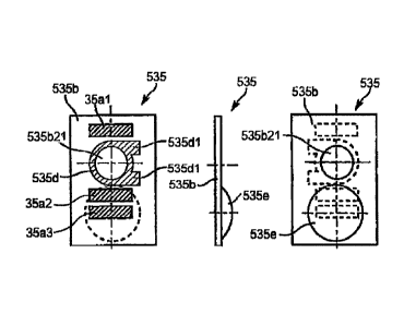
Referring to Figs. 20 to 23, the ID chip 35 (the
information storage device), the shutter member 34d, a
shutter seal 36, and the like are installed in the cap
section 34Y of the toner container 32Y.
Referring to Fig. 22, the cap section 341 has a
structure in which roughly a cylindrical section (a larger
diameter cylindrical section 3411, a medium diameter
cylindrical section 3412, and a small diameter cylindrical
section 3413) in which the outer diameter and the inner
diameter decreases from the container body 331 side toward
the shutter member 34d side in three stages is combined
with a box section (a wide width box section 34111 and a
narrow width box section 34Y12), disposed at the bottom, in
which the width in the horizontal direction decreases in
two stages are combined.
An insertion section 34z (for example, see Fig. 30)
including the larger diameter cylindrical section 3411, the
medium diameter cylindrical section 3412, the wide width
box section 34111, and part of the narrow width box section
Date Recue/Date Received 2023-03-03
34
34112 is formed in the cap section 341. The head section
33Yc of the container body 331 and part of the pumping
section 33Yb are inserted into the insertion section 34z.
Referring to Fig. 30, in the insertion section 34z, the
medium diameter cylindrical section 3412 is formed to have
the inner diameter D smaller than the tip diameter of the
gear 33c and larger than the outer diameter of the opening
A of the container body 331. Further, the small diameter
cylindrical section 34Y3 is formed to have the inner
diameter B smaller than the inner diameter D of the medium
diameter cylindrical section 34Y2 and smaller than the
outer diameter of the opening A.
An annular cap seal 37 (an elastic seal) in which the
opening diameter becomes nearly the same as the inner
diameter B is attached to an annular vertical wall surface
(the surface facing the circumference of the opening A of
the container body 331), which connects the medium diameter
cylindrical section 3412 with the small diameter
cylindrical section 3413, by a double-sided tape. The head
section 33Yc and part of the pumping section 33Yb are
inserted into the insertion section 34z such that an edge
of the opening A of the head section 33Yc of the container
body 331 comes in contact with and bites into the cap seal
37. By the above described configuration, a functional
section such as part of the gear 33c (a section excluding a
section exposed from the notch hole 34x) and a connection
section between the cap section 34Y and the container body
331 are covered with the larger diameter cylindrical
section 3411. For this reason, even when the toner
container 32 is solely held by the user, the user can be
prevented from touching the functional portion, and even if
unexpected external force (for example, careless hitting)
is applied to the toner container 321, toner leak from the ,
Date Recue/Date Received 2023-03-03
1410' '
connection section or damage of the tooth surface of the
gear 33c can be alleviated. Further, since the annular cap
seal 37 is excellent in sliding property and elasticity of
=
the surface, even if the container body 33Y rotates while
5 biting into the annular cap seal 37, there does not occur
toner leak caused by a gap generated between the container
body 33Y and the cap section 34Y. As a material of the cap
. seal 37, a high-density microcell urethane sheet having a
structure that is high in density, fine, and uniform unlike
10 general soft polyurethane foam (PUR) is used. As a result,
compared to=the case of using the general PUR, settling of
the cap seal 37 is small, and the sealing property between
the container body 331 and the cap section 341 can be
=
maintained for a long time.
15 Referring to Figs. 23.and 30, inside the narrow width
box seation.34112 positioned below the small diameter
cylindrical.section 34Y3 of the cap section 341, disposed
= is a toner falling path C having a hole of a hexagonal
cylindrical shape for discharging the toner discharged from
=
20 the opening A of the container body 331 to the container
outside downward in the vertical direction (falling by its
own weight). The toner falling path C has a predetermined
flow passage area of a hexagonal cross section and
communicates the lower side circumferential surface inside
25 the small diameter cylindrical section 34Y3 with the toner
=
discharge opening W (discharge opening), The toner
=
discharged to the inside of the small diameter cylindrical
section 3413 of the cap section 341 from the opening area A
of the container body 331 falls through the toner falling
30 path C of the hexagonal cylindrical shape by its own weight
and then is smoothly discharged from the toner discharge
opening W to the container outside (the toner tank section
61Y). =
Date Recue/Date Received 2023-03-03
36
On the bottom of the narrow width box section 34Y12,
part of the shutter member 34d (a main shutter section
34d1) for performing opening/closing of the toner discharge
opening W in conjunction with the attaching/detaching
operation of the toner container 321 to/from the toner
container storage unit 70 is held to be slidingly movable.
Figs. 22 and 23 illustrate an operation in which the
shutter member 34d starts opening of the toner discharge
opening W and then completes opening. Figs. 24(A) to 24(C)
are schematic views illustrating the opening operation of
the shutter member 34d (a shutter deforming section 34d2)
at that time. Further, Figs. 25 and 26 are perspective
views illustrating the shutter member 34d. In Figs. 24(3)
and 24(C), the cap section 341, the cap receiving section
73, and the bottle receiving section 72 which are
illustrated in Fig. 24(A) are partially omitted.
Referring to Figs. 22 to 26, the shutter member 34d is
formed of a resin material such as polystyrene and mainly
includes a plate-like main shutter section 34d1 and a
shutter deforming Section 34d2 that protrudes the main
shutter section 34d1, is thinner in thickness than the main
shutter section 34d1, and has elasticity.
Referring to Figs. 25 and 26, in the main shutter
section 34d1 of the shutter member 34d, vertical wall 34d13
standing at both side end sections (vertical walls
extending in parallel to the mounting direction of the
toner container 321) and a shutter slider 34d12 having a
plurality of protruding objects protruding from the
vertical walls 34d13 are formed on both side end sections,
respectively. The shutter slider 34d12 includes a slide,
protruding section 34d12a protruding from the inner side
surface of the vertical wall 34d13, an L-shaped engaged
protruding section 34d12b protruding from the outer side
Date Recue/Date Received 2023-03-03
37
surface of the vertical wall 34d13, and a pair of prismatic
sections 34d12c that is disposed to protrude from the same
outer side surface as the engaged protruding section 34d12b
and extends from the body of the main shutter section 34d1
to the wide width box section 34111. Meanwhile, in the
narrow width box section 34112 of the cap section 341, a
pair of slide grooves 34t (for example, see Fig. 23)
extending in both side walls in the longitudinal direction
is formed by a rib. The slide protruding section 34d12a is
fitted into the slide groove 34t, and thus the main shutter
section 34d1 of the shutter member 34d is slide-movably
supported on the cap section 34Y.
Further, a shutter seal 36 adheres to the upper
surface of the main shutter section 34d1 (the surface
facing the toner discharge opening W) as a seal member.
The shutter seal 36 is a thin rectangular parallelepiped-
like elastic seal, and similarly to the cap seal 37, a high
density microcell urethane sheet is used as a material in
view of sliding property and elasticity of the surface.
For this reason, even if the opening/closing operation of
the shutter member 34d is repeated, a sealing
characteristic in the toner discharge opening W can be
maintained in the state in which the shutter member 34d
closes the toner discharge opening W.
The slide protruding section 34d12a of the shutter
slider 34d12 is fitted into the slide groove 34t of the
narrow width box section 34112 (the cap section 341).
Further, in this state, the shutter seal 36 is sandwiched
between a protrusion 34r (for example, see Fig. 23) of a
hexagonal ring shape protruding downward along an edge of
the hexagonal toner discharge opening W of the narrow width
box section 34112 and a main shutter section 34d1, and the
shutter seal 36 becomes a slightly compressed state. In
Date Recue/Date Received 2023-03-03
38
this state, the shutter member 34d moves along the slide
groove 34t, and thus the main shutter section 34d1 opens or
closes the toner discharge opening W while suppressing
toner leak. Further, in the state in which the main
shutter section 34d1 (the shutter member 34d) has closed
the toner discharge opening W, the toner leak from between
the main shutter section 34d1 and the toner discharge
opening W is prevented.
Specifically, the shutter member 34d relatively moves
in the longitudinal direction. from the cap section 34Y side
to the container body 33Y side (moves to the left in Fig.
30) to open the toner discharge opening W and relatively
moves in the longitudinal direction from the container body
33Y side to the cap section 34Y side (moves to the right in
Fig. 30) to close the toner discharge opening W. The
opening/closing operation of the shutter member 34d (the
1 opening/closing operation of the toner discharge opening W)
is performed in conjunction with the attaching/detaching
operation of the toner container 32Y to/from the toner
container storage unit 70 (the apparatus body 100) in the
longitudinal direction.
Referring to Figs. 25 and 26, the shutter deforming
section 34d2 of the shutter member 34d is formed integrally
with the main shutter section 34d1 and formed at the board
thickness thinner than the board thickness of the main
shutter section 34d1 as described above. The shutter
deforming section 34d2 mainly includes two spindly flat
plate sections 34d23 extending from the end surface of the
main shutter section 34d1 at the container body 33Y and a
plate-like member 34d24 extending in a direction orthogonal
to the longitudinal direction to connect the two flat plate
sections 34d23 with each other near the leading end
sections (the free ends). The shutter deforming section
Date Recue/Date Received 2023-03-03
39
34d2 is formed to be elastically deformed in the vertical
direction from a fixed end (a connection portion) with the
main shutter section 34d1 as a reference point. On the
leading end sections (the free ends) of the two flat plate
5, sections 34d23, formed are stopper sections 34d22 for
fixing the shutter member 34d so as to prevent careless
opening of the toner discharge opening W as will be
described later. On the bottom side of the plate-like
member 34d24, formed is the stopper release section 34d21
that is an inclined protrusion (having a triangular cross
section) protruding, in a mountain shape, downward in the
vertical direction and that releases fixing of the shutter
member 34d in cooperation with the stopper release urging
section 72b of the cap receiving section 73 as will be
described later.
Referring to Figs. 22 and 23, in the wide width box
section 34Y11 positioned below the larger diameter
cylindrical section 34Y1 of the cap section 34Y, formed is
a shutter storage section 34n that stores the shutter
deforming section 34d2 thereinside at the time of shutter
opening. Among the four side surfaces of the wide width
box section 34Y11, the two side surfaces facing in the
longitudinal direction (a direction of an arrow in Fig. 22)
are opened. Particularly, in the side surface formed at
the toner discharge opening W side, part of the wall
surface is formed at both side ends of the bottom side, but
most of it functions as an opening 34n1 extending in the
horizontal direction. The opening 34n1 is formed such that
two surfaces including the side surface and the bottom
surface that are at the toner discharge opening W side of
the wide width box section 34Y11 are cut out. Among edge
sections of the opening 34n1, an edge section formed to
stand from the bottom surface of the wide width box section
Date Recue/Date Received 2023-03-03
40
34Y11 in the vertical direction becomes the contact section
34n5.
The stopper section 34d22 of the shutter deforming
section 34d2 is a wall section formed at a farthest end
section of the shutter deforming section 34d2 (the leading
end of the shutter deforming section 34d2 away from the
main shutter section 34d1) in the opening direction (the
left direction in Fig. 24). The stopper section 34d22 of
the shutter deforming section 34d2 comes in contact with
the contact section 34n5 and thus restricts the shutter
member 34d from moving in the direction of opening the
toner discharge opening W from the state in which the toner
discharge opening W is closed. That is, when the toner
container 32Y is in a separated state (the state in which
it is not set to the apparatus body 100 yet), since the
stopper section 34d22 of the shutter member 34d comes in
contact with the contact section 34n5, a phenomenon that
the shutter member 34d moves in the opening direction on
its own and so opens the toner discharge opening W does not
happen.
Meanwhile, the stopper release section 34d21 comes in
contact with the stopper release urging section 72b (for
example, see Figs. 5 and 24) formed in the bottle receiving
section 72 in conjunction with the mounting operation of
the toner container 32Y to the toner container storage unit
70 and is pushed upward by the stopper release urging
section 72b (as external force is applied upward). Then,
the shutter deforming section 34d2 is elastically deformed
upward, and the stopper section 34d22 is also displaced
upward. As a result, the contact state between the stopper
section 34d22 and the contact section 34n5 is released, so
that the shutter member 34d can move in the opening
direction.
Date Recue/Date Received 2023-03-03
41
An operation of the shutter member 34d in conjunction
with the mounting operation of the toner container 32Y to
the toner container storage unit 70 will be described below
in detail with reference to Figs. 24(A) to 24(C). The
position of the shutter member 34d in Figs. 24(A) and 24(C)
corresponds to the position of the shutter member 34d in
Figs. 22 and 23, respectively.
As illustrated in Fig. 24, the mounting operation of
the toner container 32Y to the toner container storage unit
70 (movement in the left direction in Fig. 24) starts, and
whep the stopper release section 34d21 of the shutter
member 34d does not reach the position of the stopper
release urging section 72b (for example, also see Fig. 5)
formed in the bottle receiving section 72, the stopper
section 34d22 of the shutter member 34d comes in contact
with the contact section 34n5, and thus movement of the
shutter member 34d in the opening direction is restricted.
Further, on the upper surface of the bottle receiving
section 72 at the cap receiving section 73 side near the
stopper release urging section 72b, a bristle brush 72f is
disposed to rub the bottom surface of the shutter member
34d and clean contamination. Particularly, the bristle
brush 72f is effective in cleaning flying toner Sticking to
the bottom surface of the shutter member 34d during an
operation of attaching/detaching the toner container 32Y.
Thereafter, when the mounting operation of the toner
container 32Y proceeds, as illustrated in Fig. 24(B), the
stopper release section 34d21 is pushed up by the stopper
release urging section 72b, and so the shutter deforming
section 34d2 is elastically deformed from the connection
position (a section encircled by an alternate long and
short dash line) as the reference point. As a result, the
contact state between the stopper section 34d22 and the
Date Recue/Date Received 2023-03-03
42
contact section 34n5 is released, and so the shutter member
34d can relatively move in the opening direction.
Thereafter, the shutter member 34d comes in contact
with the wall section (a section indicated as "contact
position" in the drawings) formed around the toner feeding
opening 73w of the cap receiving section 73, and so
movement in the toner container storage unit 70 (the cap
receiving section 73) is restricted (the shutter member 34d
does not absolutely move in the longitudinal direction).
However, since movement in the mounting direction of the
toner container 32Y is performed, the shutter member 34d
moves relative to the toner discharge opening W in the
opening direction. That is, as illustrated in Fig. 24(C),
the shutter member 34d relatively moves to the container
body 33Y side, and so the shutter deforming section 34d2 is
stored in the shutter storage section 34n. As a result,
opening of the toner discharge opening W is completely
finished by movement of the shutter member 34d in the
opening direction. Further, the toner discharge opening W
matches with the toner feeding opening 73w of the cap
receiving section 73 in a superimposed manner, and an
integrated toner feeding passage leading from the toner
container 32Y to the toner feeding device is formed. At
this time, the stopper release section 34d21 of the shutter
member 34d is stored in a notch 34n6 (for example, see Figs.
22 and 23) that is an extension section of the opening 34n1
of the cap storage section 34n. Thus, it is possible to
prevent a problem in that the shutter deforming section
34d2 stored in the shutter storage section 34n is held in a
greatly elastically deformed state by contact between the
stopper release section 34d21 and the shutter storage
section 34n.
As described above, in the toner container 32Y
Date Recue/Date Received 2023-03-03
43
according to the present first embodiment, the shutter
deforming section 34d2 that is elastically deformed from
the connection position with the main shutter section 34d1
as the reference point is disposed in the shutter member
34d, and the stopper section 34d22 that restricts movement
of the shutter member 34d in the opening direction and the
stopper release section 34d21 that releases the stopper
section 34d22 are disposed in the shutter deforming section
34d2. Thus, the shutter member 34d does not open the toner
discharge opening W as it pleases in the state in which the
toner container 32Y is removed, and only when the toner
container 32Y is set to the image forming apparatus body
100, the shutter member 34d opens the toner discharge
opening W in conjunction with the mounting operation
thereof.
An operation of the L-shaped engaged protruding
section 34d12b related to the shutter opening/closing
operation will be described below.
As illustrated in Fig. 25, the L-shaped engaged
protruding sections 34d12b are formed on both side end
sections of the main shutter section 34d1, respectively.
Meanwhile, even though not shown because it is illustrated
in the drawings of Japanese Patent Application No. 2011-
9782, on the bottom surface inside the cap receiving
section 73, a pair of urging members is installed to face a
pair of engaged protruding sections 34d12b. The pair of
urging members is an L-shaped lever (a spindle that becomes
a rotation center is formed near an L-shaped curved
portion) that forms a shape symmetrical to each other, and
an arm section at one side thereof is urged by a torsion
coil spring. If the toner container 32Y (the cap section
34Y) is mounted on the cap receiving section 73, an arm
section of the other end side of the urging member is
Date Recue/Date Received 2023-03-03
44
engaged with the engaged protruding section 34d12b and
applies urging force in a direction resisting the direction
in 'which the shutter member 34d is opened. The user pushes
the toner container 32Y by force overcoming urging force by
the above described urging member, and opening of the
shutter member 34d is rapidly performed. As a result, a
state in which the toner discharge opening W does not match
with the toner feeding opening 73w of the cap receiving
section 73 occurs only instantaneously, and toner leak from
between the toner discharge opening W and the toner feeding
opening 73w can be suppressed.
On the other hand, when the toner container 32Y (the
cap section 34Y) is removed from the cap receiving section
73, the arm section of the urging member becomes a state
urged to push the engaged protruding section 34d12b in the
mounting direction. The user attempts to pull out the
toner container 32Y by force overcoming urging force by the
urging member, and so closing of the shutter member 34d is
rapidly performed. As a result, similarly to the time of
the opening operation, toner leak from between the toner
discharge opening W and the toner feeding opening 73w can
be suppressed.
Referring to Figs. 20, 21, and 30, in the upper
section (the ceiling portion) of the cap section 34Y, the
first positioning hole 34a extending in the longitudinal
direction from the end surface of the cap section 34Y
orthogonal to the longitudinal direction is formed. The
first positioning hole 34a becomes a main positioning
reference of the cap section 34Y in the image forming
apparatus body 100. Specifically, the main reference pin
73a, (for example, see Figs. 14A, 14B and 17) as the
positioning pin of the cap receiving section 73 is fitted
into the first positioning hole 34a of the cap section 34Y
Date Recue/Date Received 2023-03-03
45
in conjunction with the mounting operation of the toner
container 32Y to the toner container storage unit 70 in the
longitudinal direction.
In the lower section (the bottom portion) of the cap
section 34Y, the second positioning hole 34b extending in
the longitudinal direction from the end surface of the cap
section 34Y orthogonal to the longitudinal direction is
formed not to reach the position of the toner discharge
opening W. The second positioning hole 34b becomes a sub
positioning reference of the cap section 34Y in the image
forming apparatus body 100. Specifically, the sub
reference pin 73b (for example, see Figs. 14A, 148 and 17)
as the positioning pin of the cap receiving section 73 is
fitted into the second positioning hole 34h of the cap
section 34Y in conjunction with the mounting operation of
the toner container 32Y to the toner container storage unit
70 in the longitudinal direction. Further, the second
positioning hole 34b as illustrated in Fig. 21 is a oblong
hole in which a vertical direction is a longitudinal
direction (this "longitudinal direction" has a different
meaning from the "longitudinal direction" of the toner
container 32Y described in the other sections).
Positioning of the cap section 34Y in the toner
container storage unit 70 is performed by the two
positioning holes 34a and 34b having the above described
configuration.
Referring to Fig. 30, the hole depth of the first
positioning hole 34a is set to be larger than the hole
depth of the second positioning hole 34b. The length of
the main reference pin 73a in the longitudinal direction is
set to be larger than the length of the sub reference pin
73b in the longitudinal direction. In the mounting
operation of the toner container 32Y to the toner container
Date Recue/Date Received 2023-03-03
46
storage unit 70 (the cap receiving section 73) in the
longitudinal direction, the main reference pin 73a starts
to be fitted into the first positioning hole 34a that is
the main positioning reference, and then the sub reference
pin 73b starts to be fitted into the second positioning
hole 34b that is the sub positioning reference, so that the
toner container 32Y can be smoothly mounted on the toner
container storage unit 70 (the cap receiving section 73).
Further, since the first positioning hole 34a that is long
in the longitudinal direction is disposed in the ceiling
section of the cap section 34? (a section that is not
buried in the toner), there is no influence on a conveying
property (a flow property) of the toner inside the cap
section 34Y. The second positioning hole 34b that is short
in the longitudinal direction is formed on the bottom of
the cap section 34? but sufficiently performs a function as
the sub positioning reference since it can be disposed
using a small space from the end surface of the cap section
34Y to the position of the toner discharge opening W.
Referring to Fig. 20, on the outer circumferential
surface of the cap section 34Y above the first positioning
hole 34a of the cap section 34Y, a guide rail section 34e
extending in an axial direction of the first positioning
hole 34a is formed.. The guide rail section 34e protrudes
upward in the vertical direction from the outer
circumferential surface of the cap section 34? to be line-
symmetrical to q virtual vertical line passing through the
hole center of the first positioning hole 34a when viewed
in a cross section orthogonal to the longitudinal direction
(a cross section parallel to a front view of Fig. 21) and
extends in the longitudinal direction (a direction vertical
to a paper plane of Fig. 21). Before the main reference
pin 73a is inserted into the positioning hole 34a, the
Date Recue/Date Received 2023-03-03
=
47
guide rail section 34e is fitted into the contacted groove
73m (a concave section), which is formed in a groove shape
in the inner wall of the cap receiving section 73 above the
main reference pin 73a, from the upstream side in the
mounting direction further than the leading end section of
the main reference pin 73a and restricts a posture of the
cap section 34Y in the horizontal direction orthogonal to
the longitudinal direction at the time of mounting movement
to the image forming apparatus body 100 (the cap receiving
section 73). Further, in the leading end of the guide rail
section 34e, a protruding section 34e1 slightly protruding
in the longitudinal direction from the end surface of the
first positioning hole 34a is formed. The protruding
section 34e1 is formed in a tapered shape as illustrated in
Fig. 20. The guide rail section 34e enters the contacted
grooves 73m formed on the cap receiving section 73, and so
the cap section 34Y is guided to the inside of the cap
receiving section 73. Thus, when the cap section 34Y is
mounted on the cap receiving section 73, in the first
positioning hole 34a, the tapered protruding section 34e1
is fitted into the contacted groove 73m before the first
positioning hole 34a is fitted into the main reference pin
73A, and thus the cap section 34Y is smoothly mounted on
the cap receiving section 73.
Referring to Figs. 20 and 21, lateral protrusions 34c
for restricting a posture of the cap section 34Y in the
rotation direction in the image forming apparatus body 100
(the cap receiving section 73) are formed on both side
sections of the cap section 34Y, respectively. The lateral
protrusion 34c protrudes to both sides in the horizontal
direction from the outer circumferential surface of the cap
sedtion 34Y to be disposed on a virtual horizontal line
passing through the center of a virtual line segment
Date Recue/Date Received 2023-03-03
48
connecting the hole center of the first positioning hole
34a with the hole center of the second positioning hole 34b
when viewed in a cross section orthogonal to the
longitudinal direction and extends in the longitudinal
direction (a direction vertical to a paper plane of Fig.
21). The two lateral protrusions 34c are engaged with the
lateral groove 73h and the groove section 73r1, for example,
illustrated in Fig. 12 while being pressed to be pushed
back in a direction opposite to pushing by the cap section
sandwiching member 73r (for example, see Fig. 12) in the
cap receiving section 73. Thus, the cap section 34Y is
attached to or detached from the cap receiving section 73
while the posture of the cap section 34Y in the rotation
direction is being restricted, and the posture of the cap
section 34Y in the rotation direction is restricted in the
state in which the cap section 34Y is mounted on the cap
receiving section 73.
In further detail, in the lateral protrusion 34c, the
leading end in the longitudinal direction (the mounting
direction) is formed in a tapered shape as illustrated in
Fig. 20. Here, when the cap section 34Y is mounted on the
cap receiving section 73, the guide rail section 34e is
first fitted into the contacted groove 73m, and then the
two lateral protrusions 34c having the tapered leading end
are fitted into the lateral grooves 73h and the groove
sections 73r1. Thus, the cap section 34Y is smoothly
mounted on the cap receiving section 73 in the state in
which the posture of the cap section 34Y is restricted with
a high degree of certainty.
Referring to Figs. 20 and 21, on both ends of the
bottom of the cap section 34Y, disposed are convex sections
344 and 34h for securing incompatibility of the toner
container 32Y (the developer container). In detail, on the
Date Recue/Date Received 2023-03-03
49
upper surface side of a flat plate-like blade member
extending laterally from the bottom of the cap section 34Y,
the convex sections 34g and 34h are disposed to protrude
upward. The convex sections 34g and 34h are configured to
be fitted into a fitting section 72m (that is formed in the
bottle receiving section 72 of the toner container storage
unit 70) illustrated in Fig. 9 when the mounting operation
of the toner container 32Y to the toner container storage
unit 70 is correct (when the toner container 32Y is mounted
to the true position of the toner container storage unit
70).
Specifically, even though not shown, the convex
sections 34g and 34h are disposed at the different
positions depending on color of the toner stored in the
toner container (the container body). In detail, if it is
assumed that the leading end in the mounting direction when
=
the toner container 32Y is mounted on the image forming
apparatus body 100 is the front, the convex sections 34g
and 34h are disposed so that the protruding positions are
not superimposed when viewed from the front and are
disposed at the different positions depending on the color.
The convex sections 34g and 34h of the toner container
corresponding to cyan are formed at the position to be
fitted only into the cyan fitting section 72m of the toner
container storage unit 70, the convex sections 34g and 34h
of the toner container corresponding to magenta are formed
at the position to be fitted only into the magenta fitting
section 72m of the toner container storage unit 70, the
convex sections 34g and 34h of the toner container
corresponding to yellow are formed at the position to be
fitted only into the yellow fitting section 72m of the
toner container storage unit 70, and the convex sections
34g and 34h of the toner container corresponding to black
Date Recue/Date Received 2023-03-03
50
are formed at the position to be fitted only into the black
fitting section 72m of the toner container storage unit 70.
The above described configuration prevents a problem
in that the toner container of a different color (for
example., the toner container of yellow) is set to the toner
container storage unit of a predetermined color (for
example, the toner container storage unit of cyan) and thus
a predetermined color image cannot be formed. That is, the
toner container is prevented from being erroneously set to
the toner container storage unit. =
Fig. 10 illustrates the state when the mounting
operation of the toner container 32Y to the toner container
storage unit 70 is correct. The convex sections 34g and
34h of the cap section 34? do not interfere with the
fitting section 72m of the bottle receiving section 72. On
the other hand, Fig. 11 illustrates the state when the
mounting operation of the toner container 32Y to the toner
container storage unit 70 is not correct. The convex
sections 34g and 34h of the cap section 34? interfere with
the fitting section 72m of the bottle receiving section 72.
The ID chip 35 (the information storage device) that
is characteristic in the toner container 32? (the removable
device) according to the present first embodiment will be
described below in detail.
Referring to Fig. 20, on the end surface of the cap
section 34Y, the ID chip 35 as the information storage
device in which various electronic information is stored is
installed at the position of a holding member 34k installed
between the first positioning hole 34a and the second
positioning hole 34b. The ID chip 35 is configured to be
connected to the connector 73e of the cap receiving section
73 in the state in which the cap section 34Y is mounted to
the toner container storage unit 70 (the cap receiving
Date Recue/Date Received 2023-03-03
51
section 73) (for example, see Figs. 3 and 17).
Specifically, in the state in which the cap section 34Y is
mounted on the toner container storage unit 70 (the cap
receiving section 73), a plurality of metallic pads 35a
(metallic plates) of the ID chip 35 come in contact with a
plurality of body side terminals 73e2'of the connector 73e.
The ID chip 35 performs communication (wire line
communication) with the control unit 90 through the
connector 73e as illustrated in Fig. 3 in the state in
which the cap section 34Y is held on the cap receiving
section 73.
Referring to Figs. 27 to 29, in the present first
embodiment, a holding mechanism installed in the toner
container 32Y (the removable device) removably installed to
the image forming apparatus body 100 includes the ID chip
35 as the information storage device, the holding member
34k as the holding section, and the like. The ID chip 35
as the information storage device held on the holding
mechanism includes a substrate 35b, an information storage
unit 35c, metallic pads 35a as a plurality of terminals
(metallic plates), and the like.
Referring to Fig. 29, the information storage unit 35c
is an electronic circuit in which various information
exchanged between the control unit 90 of the image forming
apparatus body 100 and the toner container 32Y is stored.
In Fig. 29, the information storage unit 35c is illustrated
as a box-like one by hatched lines for simplicity but
corresponds to an assembly of a memory IC, a condenser for
noise reduction, a resistor, and the like. The information
storage unit 35c is disposed on the back surface side of
the substrate 35b (the side facing the end surface of the
cap section 34Y) and electrically connected to all or some
of the metallic pads 35a as a plurality of metallic plates.
Date Recue/Date Received 2023-03-03
52
The metallic pads 35a as the plurality of terminals
come in contact with the plurality of body side terminals
73e2 of the connector 73e installed in the cap receiving
section 73 (the apparatus body 100), respectively, and
exchange an electrical signal related to information with
the image forming apparatus body 100 (the control unit 90).
The plurality of metallic pads 35a are disposed at the
front surface side of the substrate 35b (the side facing
the cap receiving section 73). Further, the plurality of
metallic pads 35a are formed in a nearly rectangular shape
and arrayed in a transverse direction thereof with a
clearance therebetween (a Z direction (vertical direction)
in Fig. 29(A)).
On the substrate 35b on which the information storage
unit 35c and the metallic pads 35a are disposed,
positioning notches 35b1 (that has a shape of a half when
an elliptical circumference is divided into two by a
straight line) are formed on both ends in the vertical
direction, respectively, The positioning notch 35b1 is
fitted into the positioning pin 73e3 (for example, see Figs,
16 and 17) as a cylindrical positioning protruding section
installed in the connector 73e (the image forming apparatus
body 100) and is used for positioning the plurality of
metallic pads 35a on the plurality of body side terminals
73e2.
The ID chip 35 (the information storage device) having
the above described configuration is held on the holding
member 34k (the holding section) that is configured
removably from the cap section 34Y.
The holding member 34k (the holding section) holds the
contact type ID chip 35 (the information storage device) to
be able to move on a virtual plane (a virtual plane
substantially orthogonal to) intersecting with the movement
Date Recue/Date Received 2023-03-03
53
direction (a direction of an arrow in Fig. 17) in which the
metallic pads 35a (terminals) approach and come in contact
with the body side terminals 73e2.
Specifically, in the present first embodiment, the
holding member 34k holds the ID chip 35 (the substrate 35b)
to be able to move on a virtual plane (an XZ plane in Fig.
20) orthogonal to the attaching/detaching direction of the
toner container 32Y to/from the image forming apparatus
body 100: That is, the ID chip 35 (the substrate 35b) is
configured to be able to move (about 1 mm) on the XZ plane
in Fig. 20 freely to some extent in a state held by the
holding member 34k (the cap section 34Y) as illustrated in
Fig. 20. Specifically, the ID chip 35 (the substrate 35b)
is held loosely to some extent inside the box-like holding
member 34k (the holding mechanism). That is, the ID chip
35 is held with a predetermined gap between the ID chip 35
and the side wall inside the holding member 34k. Referring
to Figs. 28 and 29, the ID chip 35 is held such that a
small clearance At (for example, "At+t" is about 0.85 to
1.05 mm) is formed in a Y direction on the thickness t
(about 0.8 mm) of the substrate 35b) inside the holding
member 34k. For this reason, it is possible to make the
substrate 35b stand to orthogonally cross in the insertion
direction of the positioning pin 73e3 to some extent. Thus,
prevented is a problem in that the substrate 35b is
excessively laid down in the insertion direction of the
positioning pin 73e3, the positioning pin 73e3 is seized by
the notch 35b1, and thus the positioning pin 73e3 fails to
be fitted into the notch 35b1.
Through the above described configuration, even when
the size of the image forming apparatus body 100 or the
toner container 32Y decreases and so the plurality of
metallic pads 35a (terminals) on the substrate 35b are
Date Recue/Date Received 2023-03-03
54
densely arranged so as to reduce the size of the ID chip 35
installed thereon, a contact failure that is caused by a
positioning failure between the plurality of metallic pads
35a and the body side terminal 73e2 of the connector 73e is
difficult to occur regardless of whether or not a degree of
dimension accuracy or a degree of assembly accuracy of an
associated component is high or low.
Specifically, referring to Fig. 17, if the mounting
operation of the cap section 34Y of the toner container 32Y
on the cap receiving section 73 proceeds, the positioning
pins 73a and 73b are inserted into the positioning holes
34a and 34b, and so the cap section 34Y is positioned in
the cap receiving section 73. If the mounting operation of
the cap section 34Y further proceeds, the positioning pin
73e3 of the connector 73e (for example, see Figs. 16 and .
17) is inserted into the notch 35b1 of the substrate 35b of
the ID chip 35, and the substrate 35b (the plurality of
metallic pads 35a) is positioned with respect to the
connector 73e (the plurality of body side terminal 73e2).
In further detail, the positioning pin 73e3 comes in
contact with the edge section (or the inner surface) of the
notch 35b1, and so movement of the substrate 35b is
restricted. At this time, since the ID chip 35 (the
substrate 35b) having the notch 35b1 formed therein is
configured to be movable on the XZ plane in the holding
member 34k, an allowable tolerance of a degree of dimension
accuracy or a degree of assembly accuracy of an associated
component according to mass production has to be large.
Thus, when positioning between the toner container 321 and
the image forming apparatus body 100 is performed, even if
the position of the notch 35b1 is misaligned with the
positioning pin 73e3 from the beginning, the ID chip 35
(the substrate 35b) is restricted by the tapered leading
Date Recue/Date Received 2023-03-03
55
end of the positioning pin 73e3 and moves on the XZ plane,
and thus the cylindrical section of the positioning pin
73e3 can be fitted into the notch 35b1. That is,
independently of positioning between the toner container
32Y and the image forming apparatus body 100, the
cylindrical section of the positioning pin 73e3 can be
fitted into the notch 35b1. Thus, the contact failure that
is caused by the positioning failure between the plurality
of metallic pads 35a and the body side terminals 73e2 of
the connector 73e is difficult to occur.
. Referring to Fig. 27, the holding member 34k as the
holding section is removably configured on the cap section
34Y and is a box-like member having an insertion opening
34k1, formed in the upper side thereof, through which the
ID chip 35 is inserted or separated.
In detail, when assembling the holding mechanism to
the cap section 34Y, the ID chip 35 (the information
storage device) is first inserted into the holding member
34k through the insertion opening 34k1 (movement in a
direction of an arrow in Fig. 27). Thereafter, the holding
member 34k (the holding section) having the ID chip 35
mounted thereon moves in the arrow direction in Fig. 27 and
is press-fitted into the convex section of the cap section
34Y. At this time, the holding member 34k is fixed and
held at the position contacting a pedestal section 34q
(disposed at the position not contacting the substrate 35b)
disposed in the convex section of the cap section 34Y.
Further, when ejecting the ID chip 35 from the cap section
34Y, an operation is performed in a procedure reverse to
the above described procedure. The pedestal section 34q is
a rib standing in the mounting direction of the toner
container 32Y (or toward the holding member 34k) inside the
concave section of the cap section 34Y and disposed at the
Date Recue/Date Received 2023-03-03
56
position other than a place into which the positioning pin
73e3 of the connector 73e is to be inserted.
In the present first embodiment, the holding member
34k is press-fitted into and fixed to the concave section
of the cap section 34Y, but the holding member 34k may be
mounted on and screw-fixed to the concave section of the
cap section 34Y. Specifically, a flaky rib having a hole
in the side wall of the holding member 34k protrudes to
form a female screw section in the end surface of the cap
section 34Y. The holding member 34k is mounted on the
concave section of the cap section 34Y, and in the state in
which the flaky rib of the holding member 34k comes in
contact with the end surface of the cap section 34Y, a
screw is screwed into the female screw section of the cap
section 34Y through the hole of the rib related to the
holding member 34k. Even in this configuration, the
holding member 34k can be comparatively easily attached to
or detached from the cap section 34Y.
As described above, since the ID chip 35 (the
substrate 35b) is configured to be attached to or detached
from the cap section 34Y, efficiency of assembling the TO
chip 35 (the substrate 35b) to the toner container 32Y as
the removable device increases, and at the same time,
efficiency of a disassembly operation of the ID chip 35
(the substrate 35b) when recycling the toner container 32Y
increases. Particularly, in the present first embodiment,
the substrate 35b of the ID chip 35 is a small substrate
having the size of about 12 mm x 8 mm to 15 mm x 10 mm. If
data input/output (data input/output when a probe terminal
comes in contact with the metallic pad 35a) is about to be
performed in the state in which the substrate 35b is
mounted on the cap section 34Y in the manufacturing process,
it may be difficult to do a work on the cap section 34Y of
Date Recue/Date Received 2023-03-03
57
a complicated shape, and a process time may increase. Thus, '
in the present first embodiment, the ID chip 35 (the
substrate 35b) is removably configured, and thus there is a
great effect since a data input/output operation can be
performed on the ID chip 35 alone (or for each holding
member 34k) if necessary.
Referring to Figs. 17 and 27, in the cap section 34Y,
formed is a standing member 34f that blocks the insertion
opening 34k1 in the state in which the holding member 34k
is mounted on the concave section.
Thus, prevented is a problem in that the ID chip 35
falls off from the insertion opening 34k1 of the holding
member 34k after the ID chip 35 (the holding member 34k) is
mounted on the cap section 34Y.
Referring to Fig. 28, inside the holding member 34k
(the box-like member), formed are a first facing section
34k4 and a second facing section 34k5. The first facing
section 34k4 faces a first plane of the substrate 35b
(referring to Fig. 29, a surface where the plurality of
metallic pads 35a are disposed) and is formed to come in
contact only with and slide on an outer peripheral area of
the first plane where the metallic pads 35a are not
disposed so as not to interfere with the plurality of
metallic pads 35a. The second facing section 34k5 faces a
second plane of the substrate 35b (referring to Fig. 29, a
surface where the information storage unit 35c is disposed)
and is formed to slide on part of the second plane so as
not to interfere with the information storage unit 35c.
Thus, inside the holding member 34k, the ID chip 35 can
freely move on the XZ plane (can move to slide on the
facing sections 34k4 and 34k5) without falling off from the
holding member 34k, and without the metallic pads 35a or
the information storage unit 35c getting damaged.
Date Recue/Date Received 2023-03-03
58
Further, openings 34k2 and 34k3 are formed in the
front and back surfaces of the holding member 34k,
respectively. The first opening 34k2 is formed to allow
the plurality of metallic pads 35a and the positioning
notch 35b1 to be exposed at the side facing the connector
73e even when the substrate 35b moves in the XZ plane to
some extent. Thus, in accompany with movement of the
substrate 35b in the XZ plane, the positioning pin 73e3 and
the notch 35b1 can be engaged with each other, and the
metallic pads 35a and the body side terminals 73e2 can be
connected with (come in contact with) each other. Further,
the second opening 34k3 to allow the information storage
unit 35c to be exposed at the side facing the concave
section of the cap section 34Y even when the substrate 35b
moves on the XZ plane to some extent.
Referring to Fig. 28, the opening 34k2 formed in the
front surface of the holding member 34k is formed such that
the left side has a convex shape and the right side has a
concave shape. Thus, an area encircled by a dotted line in
Fig. 28 functions as a hook (a stopper) for preventing the
ID chip 35 from falling off from the opening 34k2.
Fig. 29 is a three-plane view illustrating the ID chip
35.
As illustrated in Fig. 29, in the ID chip 35, the
metallic pads 35a as four metallic plates are disposed in
line in the Z direction on the first plane of the substrate
35b. The metallic pad 35a has a multi-layer structure
having three layers of a copper layer, a nickel layer, and
a metallic layer which are disposed in order from the
substrate 35b side, and the metallic layer as the surface
layer is comparatively expensive but disposed to prevent
oxidization. The metallic pad 35a is formed by electric
field evaporation on the substrate 35b that is masked in
Date Recue/Date Received 2023-03-03
59
advance.
The positioning notches 35b1 are formed on both end
sections of the four metallic pads 35a in the arrangement
direction (the Z direction) to sandwich the four metallic
pads 35a. In the present first embodiment, a first virtual
straight line Si that passes through the centers of the
notches 35b1 and is parallel to the arrangement direction
of the plurality of metallic pads 35a is configured to be
positioned not to overlap a second virtual straight line S2
that connects the centers of the plurality of metallic pads
35a in the longitudinal direction. Specifically, the first
virtual straight line Si that connects the two positioning
notches 35b1 (a virtual line that connects the centers of
original oblong holes in the notches 35b1 each of which has
a shape of a half when the oblong hole is divided into two
in the longitudinal direction) is configured to be
positioned not to overlap the second virtual straight line
S2 that connects the centers of the plurality of metallic
pads 35a in the longitudinal direction. That is, in the
notches 35b1, the virtual straight line Si that connects
sections that are most bitten toward the inside of the
substrate 35b is positioned not to overlap the virtual
straight line S2. Further, the virtual straight line Si is
configured to be nearly parallel to the virtual straight
line S2.
In the present first embodiment, dimensions a to f in
Fig. 29 have been set to 6.2 mm, 5.2 mm, 1.5 mm, 2 mm, 6 mm,
and 11.7 mm, respectively. The substrate 35b having the
small area size is small in deflection amount even if
external force is applied and comparatively large in
resistance characteristic (stiffness) against shearing
force. In the present first embodiment, the ID chip 35 is
held to be movable inside the holding member 34k, and
Date Recue/Date Received 2023-03-03
60
employed is a positioning method in which the positioning
pin 73e3 is inserted into the notch 35b1 and is likely to
be "seized" (a state in which the positioning pin 73e3
enters the notch 35b1 obliquely rather than vertically, a
sliding load between the notch 35b1 and the positioning pin
73e3 increases, and so the substrate 35b is deflected and
does not move) in the case of the ID chip 35 having the
large area size. However, since the substrate 35b has the
small area size, stiffness increases, and so the
positioning method that is difficult to cause deflection
that causes "seizure" is implemented. Further, an interval
between the metallic pads 35a in the substrate 35b is
narrow, but the contact failure between the metallic pads
35a and the body side terminals 73e2 can be prevented by
high accuracy positioning in accompany with movement of the
substrate 35b in the XZ plane, and thus the area size of
the expensive metallic pads 35a having the metal layer can
be Suppressed to a minimal area size.
Fig. 16 is a schematic perspective view illustrating
the connector 73e at the apparatus body 100 side,
Referring to Fig. 16, the four body side terminals
73e2 in the connector 73e are plat-like (linear) metallic
members, have one end as the fixed end and the other end as
the free end, and are fixed to and supported on the
connector body 73e1. On the other end sides of the four
body side terminals 73e2, formed are curved sections that
curve toward the ID chip 35 (toner container 32Y) side,
That is, the body side terminals 73e2 curve toward the ID
chip 35 like a knee (or a boomerang). The curved sections
of the body side terminals 73e2 are sections that functions
as contact points with the metallic pads 35a.
In accompany with the mounting operation of the cap
section 34Y (the toner container 32Y) on the cap receiving
Date Recue/Date Received 2023-03-03
61
section 73, the curved section of the body side terminal
73e2 comes in contact with nearly the central section of
the metallic pad 35a in the longitudinal direction. Then,
when the mounting operation of the cap section 34Y further
proceeds, the ID chip 35 (the substrate 35b) approaches to
the connector 73e side, the body side terminal 73e2 is
deformed so that the curved section of the body side
terminal 73e2 get close to the first virtual straight line
Si while being pressed by the metallic pad 35a and
elastically deformed (a state in which a curved knee
stretches). That is, in accompany with the mounting
operation of the cap section 34Y, the curved section of the
body side terminal 73e2 slides toward the left in Fig. 29
from the central section in the longitudinal direction
(approaches the first virtual straight line Si) while
gradually increasing contact pressure on the metallic pad
35a.
Through the above described configuration, even if the
position of the cap section 34Y (the metallic pad 35a) in
the longitudinal direction (the Y direction) is misaligned
with the cap receiving section 73 (the body side terminal
73e2) depending on whether or not a degree of dimensions
accuracy or a degree of assembly accuracy of an associated
component is high or low (a dimension variation), the
contact failure between the body side terminal 73e2 and the
metallic pad 35a can be prevented with a high degree.
Finally, since the body side terminal 73e2 and the metallic
pad 35a come in contact with each other near the position
where the positioning pin 73e3 is engaged with the notch
35b1 (near the first virtual straight line Si),.the
distance between the positioning section and the connect
section can be reduced. As a result, a degree of accuracy
of the contact position between the body side terminal 73e2
Date Recue/Date Received 2023-03-03
62
and the metallic pad 35a increases.
Further, in the present first embodiment, the
plurality of metallic pads 35a are disposed in line in the
arrangement direction that is the vertical direction.
As a result, the positioning direction of the cap
section 34Y in the cap receiving section 73 (the
arrangement direction of the positioning pins 73a and 73b
and the positioning holes 34a and 34b) is the same as the
positioning direction of the connector 73e and the
substrate 35b (the arrangement direction of the positioning
pin 73e3 and the notch 35b1), and thus the contact failure
between the body side terminal 73e2 and the metallic pad
35a is difficult to occur.
Referring to Fig. 21, the positioning holes 34a and
34b of the cap section 34Y are formed at positions apart
from each other in the vertical direction to sandwich the
ID chip 35 (the information storage device). A third
virtual straight line S3 that connects the centers of the
two positioning holes 34a and 34b is configured to be
parallel to the first virtual straight line Si that
connects the two positioning notches 35b1.
As described above, since the ID chip 35 is disposed
be fixed between the first positioning hole 34a (the main
reference) and the second positioning hole 34b (the sub
reference), the position of the ID chip 35 with respect to
the connector 73e of the cap receiving section 73 is
decided with a high degree of accuracy. Thus, the
communication failure caused by position misalignment
between the connector 73e and the ID chip 35 can be
suppressed. Particularly, since the positioning direction
of the cap section 34Y in the cap receiving section 73 (the
arrangement direction of the positioning pins 73a and 73b
and the positioning holes 34a and 34b) is the same as the
Date Recue/Date Received 2023-03-03
63
positioning direction of the connector 73e and the
substrate 35b (the arrangement direction of the positioning
pin 73e3 and. the notch 35b1), the positioning operation of .
the toner container 32Y on the image forming apparatus body
.5 100 contributes to making it easier to position of the
substrate 35b on the connector 73e. As a result, there is
an effect in that the contact failure between the body side
= terminal 73e2 and the metallic pad 35a is difficult to
occur.
Further, a procedure in which components of the bottle.
receiving section 72 and the cap receiving section 73 are
concerned with the cap section 341 when the mounting
operation of the toner container 321 on the toner container
storage unit 70 proceeds is as follows.
First, the cap section 34Y slides on the bottle =
. receiving surface 72a, and thereafter, the guide rail
section 34e of the cap section 34Y is fitted into the
= =
engaged groove 73m of the cap receiving section 73, the
lateral protrusion 34c of the cap section 34Y is fitted
into the lateral groove 73h and the groove section 73r1 of.
the cap receiving section 73,.and the posture of the cap
section 341 in the cap receiving section 73 in the vertical
and horizontal directions is restricted. At this time,
shaking of the cap section 341 before being inserted into
the cap receiving section 73 is prevented by the cap
section sandwiching member 73r. The first positioning hole
34a of the cap section 34Y is fitted into the main
reference pin 73a of the cap receiving section 73, and so
positioning of the main reference is performed. Thereafter,
the second positioning hole 34b of the cap section 341 is
= fitted into the sub reference pin 73b of the cap receiving
'section 73, and so' main and sub positioning is completed.
Further, while the positioning is being completed, the .
Date Recue/Date Received 2023-03-03
64
contact state between the stopper section 34d22 of the
shutter member 34d of the cap section 34Y and the contact
section 34n5 is released by the stopper release urging
section 72b, and the postures of the shutter member 34d and
the cap section 34Y in the cap receiving section 73 are
decided by a body side shutter closing mechanism (not
shown). In this state, the opening operation of the
shutter member 34d is performed. The toner discharge
opening W opened in the cap section 34? is communicated
with the toner feeding opening 73w of the cap receiving
section 73. The notch 35b1 of the ID chip 35 of the cap
section 34Y is engaged with the positioning pin 73e3 of the
connector 73e of the apparatus body 100, the position of
the ID chip 35 in the cap section 34Y is decided, and the
plurality of metallic pads 35a of the ID chip 35 come in
contact with the plurality of body side terminals 73e2 of
the connector 73e, respectively, with a high degree of
certainty. Thus, setting of the cap section 34? (the toner
container 32Y) in the cap receiving section 73 (the toner
container storage unit 70) is completed. At this time, the
gear 33c of the container body 33? meshes with the driving
gear 81 of the apparatus body 100.
e Meanwhile, when extracting (removing) the toner
container 32Y from the toner container storage unit 70 (the
cap receiving section 73), the procedure reverse to the
procedure at the time of mounting is performed.
As described above, in the image forming apparatus
according to the present first embodiment, as the user
perfcrms one action of moving the toner container 32? in
the longitudinal direction while gripping the gripping
section 33d (excluding the opening/closing operation of the
body cover), the opening/closing operation of the toner
discharge opening W by the shutter member 34d is also
=
Date Recue/Date Received 2023-03-03
65
performed in conjunction with the operation, and the
mounting operation and the removing operation of the toner
container 32Y is completed.
Further, in the toner container 32Y according to the
present first embodiment, the toner discharge opening W
having the comparatively large opening area size is
disposed downward in the vertical direction, and so the
toner can be discharged such that it falls directly from
the toner discharge opening W by its own weight.
Further, since the toner container 32Y is not placed
from above the toner container storage unit 70 (the
apparatus body 100) but attached to or detached from the
front surface of the toner container storage unit 70 (the
apparatus body 100), a degree of freedom of the layout
above the toner container storage unit 70 increases. For
example, even when a scanner (a document reading section)
is disposed directly above the toner feeding device,
operability or workability at the time of
attachment/detachment of the toner container 32Y does not
deteriorate.
Further, since the toner container 32Y is disposed in
the apparatus body 100 such that the longitudinal direction
is the horizontal direction, it does not have any influence
on the overall layout of the image forming apparatus body
100 in the height direction. The toner capacity of the
toner container 32Y increases, and so the replacement
frequency can be reduced.
As described above, in the present first embodiment,
the contact-type ID chip 35 (the information storage
device) is held on the holding member 34k (the holding
section) to be movable on the virtual plane that is
substantially orthogonal to the movement direction in which
the metallic pads 35a (terminals) approach and come in
Date Recue/Date Received 2023-03-03
66
contact with the body side terminals 73e2. Thus, even when
the contact-type ID chip 35 (the information storage
device) is installed in the toner container 32Y (the
removable device) installed removably on the image forming
apparatus body 100, the contact failure caused by the
positioning failure with the body side terminals 73e2 of
the connector 73e of the image forming apparatus body 100
is difficult to occur.
Second Embodiment
A second embodiment of the present invention will be
described in detail with reference to Figs. 31 to 33.
Fig. 31 is a schematic cross sectional view
illustrating a toner container 232Y according to the
present second embodiment. Fig. 32 is a back view
illustrating a cap section 234Y of a toner container 232Y.
Fig. 33 is a perspective view illustrating a holding cover
234k8 that is fitted into a holding member 234k.
The toner container 232Y according to the present
second embodiment is different from the first embodiment in
configuration of the holding member 234k in a holding
mechanism for holding the information storage device.
Similarly to the first embodiment, the toner container
232Y according to the present second embodiment includes
the container body 33Y and a cap section 234Y. The ID chip
as the information storage device is removably installed
in the cap section 234Y.
In the cap section 234Y according to the present
second embodiment, the holding member 234k in which the
30 opening 34k2 exposing part of the ID chip 35 (the metallic
pads 35a and the notch 35b1) is formed is integrally formed.
The ID chip 35 is inserted into from the inner side of
the cap section 234Y in a direction of an arrow in Fig. 31
Date Recue/Date Received 2023-03-03
67
and set at the position of the holding member 234k. In the
= state in which the ID chip 35 is set at the position of
the holding member 234k, the holding cover 234k8 is
inserted into from the inner side of the cap section 234Y
S in the direction of the arrow, in Fig. 31 and fitted into
the holding member 234k (the state of Fig. 32).
= In the holding cover 234k8, a pedestal section 234q
that is fitted into the holding member 234k is disposed so
as not to come in contact with the substrate 35b.
Further, the holding cover 234k8 is tightly installed
= without a clearance with the inner wall of the cap section
234Y so as to prevent the toner leaking from the toner
container 232Y from sticking to the ID chip 35. =
Even in the present second embodiment, the ID chip 35
(the substrate 35b) is held in the holding member 234k (and
the holding cover 234k8) to be movable on the XZ plane.
= As described above, sithilarly to the first embodiment,
even in the present second embodiment, the contact-type ID
chip 35 (the information storage device) is held on the
holding member 234k (the holding section) to be movable on
the virtual -plane that is substantially orthogonal to the
movement direction in which the metallic pads 35a =
(terminals) approach and come in contact with body side
terminals 73e2. Thus, even when the contact-type ID chip
35 (the, information storage device) is installed in the
toner container 232Y (the removable device) installed
removably on the image forming apparatus body 100, the
= contact failure caused by the positioning failure with the
=
body side terminals 73e2 of the connector 73e of the image =
forming apparatus body 100 is difficult to occur. =
= Third Embodiment
A third embodiment of the present invention will be '
Date Recue/Date Received 2023-03-03
68
described in detail with reference to Fig. 34.
Fig. 34 is a schematic view illustrating a state in
which the information storage device 35 of a toner
container 332Y according to the present third embodiment is
set to the connector 73e of the cap receiving section 73.
Fig. 34 is a view corresponding to Fig. 27 in the first
embodiment.
The present third embodiment is different from the
first embodiment in that a cushion material 334k10 is
installed inside the holding member 34k and a configuration
of a wall section 373g of a cap receiving section 373 is
different.
Similarly to the above embodiments, a toner container
332Y according to the present third embodiment includes a
container body 33Y and the cap section 34Y. The ID chip 35
as the information storage device is removably installed in
the cap section 34Y. Further, the ID chip 35 is held in
the holding member 34k to be movable in the XZ plane.
In the present third embodiment, the cushion material
334k10 is disposed between the inner wall (the second
facing section 34k5) of the holding member 34k and the
substrate 35b. The cushion material 334k10 is made of an
elastic material such as foamed polyurethane, and a low
frictional material adheres to a section facing the
substrate 35b. Thus, it is possible to alleviate damage
occurring in the substrate 35b when the positioning pin
73e3 is engaged with the notch 35b1 without hindering
movement of the ID chip (the substrate 35b) in the XZ plane.
In the present third embodiment, the wall section 373g
of the cap receiving section 373 is installed to surround '
four sides of the connector 73e. In order to cope with it,
the concave section for avoiding interference with the wall
section 373g is formed in the cap section 34Y. By
Date Recue/Date Received 2023-03-03
69
disposing the wall section 373g as described above, even if
the toner is scattered from the vicinity of the toner
discharge opening W of the toner container 332Y to the
outside, the scattered toner is difficult to stick directly
to the connector 73e or the ID chip 35. Thus, the contact
failure (the communication failure) between the connector
73e (the body side terminal 73e2) and the ID chip 35 (the
metallic pad 35a) caused by the scattered toner can be
prevented.
As described above, similarly to the above embodiments,
even in the present third embodiment, the contact-type ID
chip 35 (the information storage device) is held on the
holding member 34k (the holding section) to be movable on
the virtual plane that is substantially orthogonal to the
movement direction in which the metallic pads 35a
(terminals) approach and come in contact with body side
terminals 73e2. Thus, even when the contact-type ID chip
35 (the information storage device) is installed in the
toner container 332Y (the removable device) installed
removably on the image forming apparatus body 100, the
contact failure caused by the positioning failure with the
body side terminals 73e2 of the connector 73e of the image
forming apparatus body 100 is difficult to Occur. .
Fourth Embodiment
A fourth embodiment of the present invention will be
described in detail with reference to Fig. 35.
Fig, 35 is a three-plane view illustrating a substrate
435b of an information storage device 435 according to the
present fourth embodiment. Fig. 35 is a view corresponding
to Figs. 14A and 148 in the first embodiment.
Similarly to the above embodiments, a toner container
(432y) according to the present fourth embodiment also
Date Recue/Date Received 2023-03-03
70
includes the container body 33Y and the cap section 34Y.
The ID chip 435 as an information storage device is
removably installed in the cap section 34Y. Further, the
ID chip 435 is held in the holding member 34k to be movable
in the XZ plane.
In a substrate 435b of the ID chip 435 according to
the present third embodiment, instead of the positioning
notch 35b1 in the above embodiments, positioning holes
435b11 and 435b12 are disposed. In accompany with the
mounting operation of the toner container (432Y), the
substrate 435b freely moves in the XZ plane, and the
positioning holes 435b11 and 435b12 are engaged with the
positioning pins 73e3 of the connector 73e. Specifically,
edges (or inner surfaces) of the holes 435b11 and 435b12
come in contact with the positioning pins 73e3, and
movement of the substrate 435b is restricted. Thus, the
contact failure caused by the positioning failure between
the plurality of metallic pads 35a and the body side
terminals 73e2 of the connector 73e is difficult to occur.
In the present fourth embodiment, in view of the fact
that the substrate 435b is positioned at the lower side of
the holding member 34k due to the weight of the substrate
435b directly before the positioning holes 435b11 and
435b12 are engaged with the positioning pins 73e3, the
circular hole 435b11 is formed in the lower section of the
substrate 435b, and the elliptical hole 435b12 is formed in
the upper section of the substrate 435b. The hole 435b11
in the lower section is picked up by the positioning pin
73e3, and so the substrate 435b is raised, and the
positioning pin 73e3 is smoothly inserted into the other
elliptical hole (the hole 435b12). If the hole in the
lower section is the elliptical hole and the hole in the
upper section is the circular hole, the substrate 435b may
Date Recue/Date Received 2023-03-03
=
71
not be raised by the positioning pin 73e3, and the
positioning pin 73e3 may be difficult to be inserted
=
into the circular hole in the upper portion.
In the present fourth embodiment, the two positioning
holes 435b11 and 435b12 are formed in the substrate 35b of
the ID chip 35. On the other. hand, in the substrate 435b
of the ID chip 435, one may be formed of the positioning
holes 435b11 (or 435b12), and the other may be formed of
the positioning notch 35b1 (that has been used in the above
embodiments). Even in this case, the same effect as in the
present fourth embodiment can be obtained.
= As described above, similarly to the above embodiments,
even in the present fourth embodiment, the contact-type ID
= = chip 435 (the information storage device) is held on the
holding member 34k '(the holding section) to be movable on
=
the virtual plane that is substantially orthogonal to the
movement direotion in which the metallic pad a 35a
= 4terminals)- approach and come in contact with body side =
terminals 73e2. Thus, even.when the contact-type ID chip
= .20 435 (the information storage device) is installed in the
toner container (the removable device) installed removably
. .
on the image forming apparatus body 100, the contact
=
failure caused by the positioning failure with the body
side terminals 73e2 of the connector 73e of the image .
forming apparatus body 100 is difficult to occur.
Fifth Embodiment
A fifth embodiment of the present invention will be
described in detail with reference to Figs. 36 to 41.
. 30* Fig. 36 is a three-plane view illustrating a substrate
of an information storage device 535 according to the =
present fifth embodiment and is a view corresponding to Fig.
29 in the first embodiment. Fig. 37 is a perspective view
Date Recue/Date Received 2023-03-03
72
illustrating the information storage device 535, a holding
member 534k (534k25), and a connector 573e and is a
perspective view illustrating a relative positional
relation of the three members 534k (534k25), 535, and 573e.
Fig. 38 is a perspective view illustrating a condition in
which the information storage device 535 is engaged with
the connector 573e. Figs. 39A and 39B are circuit diagrams
illustrating an electric circuit of the information storage
device 535 and an electric circuit of the connector 573e.
Fig; 40A is a front view illustrating a condition in which
the information storage device 535 is held on the connector
573e, and Fig. 40B is a front view illustrating a condition
in which the information storage device 535 is rotating on
a positioning hole 535b21. Fig. 41 is a view illustrating
the information storage device 535 that comes in contact
with a probe 400 in an inspection process when manufactured
in a factory.
The present fifth embodiment is different from the
first to fourth embodiments in that only one positioning
hole 535b21 is formed in the substrate 535b of the
information storage device 535, and the positioning hole
535b21 is disposed between a plurality of rectangular
metallic pads 35a1, 35a2, and 35a3 (metallic pads).
Referring to Fig. 36, the ID chip 535 as the
information storage device according to the present fifth
embodiment has the positioning hole 535b21 that is formed
at the upper position in the vertical direction further
than the gravity center of the substrate 535b. An earth
metallic terminal 535d is disposed on an inner surface of
= 30 the hole 535b21 and around the hole 535b21. In the present
fifth embodiment, the metallic terminal 535d formed on the
surface of the substrate 535b includes two protruding
sections 535d1 that are formed to extend from a rink-like
Date Recue/Date Received 2023-03-03
73
section in the horizontal direction.
Further, the rectangular metallic pad 35a1 is
installed above the positioning hole 535b21 in the vertical
direction, and the two rectangular metallic pads 35a2 and
35a3 are installed below the positioning hole 535b21 in the
vertical direction.
Further, on the back side of the substrate 535b (the
side facing the cap section 34Y), a protection member 535e
that is made of a resin material having a substantially
hemispherical shape or a shape of an inverted pan such as
epoxy and covers the information storage unit is disposed.
In the present fifth embodiment, although it depends on the
shape of the substrate 535b or the
configuration/arrangement of the back surface such as the
protection member 535e, by disposing the hole 535b21 above
the protection member 535e that may include the information
storage unit such an integrated circuit (IC) thereinside
and is a heaviest component, a positional relation in which
the hole 535b21 is installed vertically above the gravity
center of the ID chip 535 is implemented. Specifically,
referring to Fig. 40A, the ID chip 535 (the information
storage device) according to the present fifth embodiment
is formed so that the center position of the positioning
hole 535b21 is at the distance Za above the gravity center
of the ID chip 535.
Referring to Fig. 37, the connector 573e includes a
connector body 573e21 that is made of resin and is a hollow
box, and a positioning pin 573e23 (a positioning protruding
section) that is a hollow cylinder and having a tapered tip
is disposed on the connector body 573e21 to stand in the
horizontal direction. A body side earth terminal 573e25
(an earth terminal) is installed in the positioning pin
573e23. The body side earth terminal 573e25 is a plat-like
Date Recue/Date Received 2023-03-03
74
(or linear) metallic member, partially stored in the hollow
section of the positioning pin 573e23 formed integrally
with a connector 573e21, and has a curved section that is
exposed from a slit-like opening formed in part of the
circumferential surface of the hollow cylinder and
protrudes from the cylindrical outer circumferential
surface. Further, one body side terminal 573e2 is
installed vertically above the positioning pin 573e23 (the
body side earth terminal 573e25), and two body side
terminals 573e2 are installed vertically below the
positioning pin 573e23 (the body side earth terminal
573e25). The body side terminals 573e2 are plat-like (or
linear) metallic members and are formed almost in the same
manner as in the above embodiments except that the
installation position is different.
Further, swing preventing members 573e24 as a pair of
guiding members protrude from the right and left sides of
the positioning pin 573e23. The guiding members include a
pair of plates whose tips have inner tapered surfaces ,
facing each other and the guide the both sides of the ID
chip 535 to be upright.
Similarly to the above embodiments, the holding member
534k (the holding section) is fixed to a toner container
(532X) and positioned between the connector 573e and the ID
chip 535. The holding member 534k has almost the same
function (a function for movably holding the ID chip 35) as
In the above embodiments, Referring to Fig. 37, the
holding member 534k according to the present fifth
embodiment has a first facing section 534k24 that is
'configured to be linearly symmetrical on an center axis in
the vertical direction and is formed to cover an area from
two Upper corners of the ID chip 535 to both sides of the
hole 535b21. The holding member 534k is formed to cover
Date Recue/Date Received 2023-03-03
75 =
the lower section of the substrate 535b further than the
lowest metallic pad 35a3, and through the above described e
= configuration, the ID chip 535 is prevented from falling =
. from the holding member 534k.
Further, in the holding member 534k, the first facing
section 534k24 including an area facing the four body side
terminals 573e2 and 573e25 of the connector 573e is formed
of an opening. Particularly, in the holding member 534k, . .
formed is an' opening 534k22 that is opened up to a section
corresponding to a pair of swing preventing members 573e24.
At the time of mounting of the toner container 532Y, the
positioning pin 573e23 is inserted into the opening 534k22,
and thereafter the pair of swing preventing members 573e24
(the pair of guiding members) is also inserted into the
holding member 534k through the opening 534k22.
A second facing section 534k25 of a flat plate form
facing the back surface of the ID chip 535 (the side of the
holding member 535e) is fixed to the holding member 534k by
adhesion or a snap fit (not shown). The second facing
section 534k25 includes a opening 534k26 similarly to the
opening 534k22 and so can avoid interference with the
holding members 535e or the inserted swing preventing member
573e24.. Meanwhile, when the positioning pin 573e23 is
inserted into the hole 535b21 of the ID chip 535, the ID
chip 535 is pushed, but since the second facing section
534k25 supports the substrate 535b from the rear side, the
contact condition between the terminals can be maintained. .
Fig. 3g. is a schematic perspective view illustrating
the condition in which positioning of the connector 573e
and the ID chip 535 at the apparatus body 100 side is
=
completed. The condition is that the toner container 532Y
according to the fifth embodiment is mounted on the
apparatus body 100, and the body side terminals 573e2 and
Date Recue/Date Received 2023-03-03
76
573e25 are connected with the abovementioned metallic pads
=
35a1 to 35a3 and the earth terminal 535d. In Fig. 38, for
the sake of easy understanding, the holding member 534k
(534k25) between the connector 573e and the ID chip 535 and
the metallic pads 35a1 to 3543 are omitted.
When mounting the toner container 5321 on the image
= forming apparatus body, the main and subordinate
positioning =holes 34a and 34b of the cap section 534Y are
fitted into the main and subordinate positioning pins 73a
and 73b of the cap receiving section 73, and positioning of
the cap section 534Y is performed. This mounting operation
=
is the same as the mounting operation of the first
dmbodiment. After the position of the cap section 5341 is
= decided, the hole 535b21 of the ID chip 535 is fitted into
the positioning pin 573e23 to be picked up by the tapered
tip of the positioning pin 573e23 of the connector 573e. As
a rdsult, the position of the ID chip 535 in the horizontal
direction and the vertical direction is decided at the same,
time. Further, as illustrated in Fig. 401 , the swing
preventing members 573e24 (the pair of guiding members) of
the connector 573e that includes the pair of plates are
=
inserted into the lower edge portions that are at both
right and left sides of the substrate 535b and at the lower
area further than the center of the hole 535b21. At this
time, it is a possible case that the posture of the ID chip'
is misaligned as illustrated in Fig. 40B. Even in this case,
= if the inner tapered surfaces of the plates come& in
contact with the lower edge portions, it causes the
=
substrate 535b to rotate in a direction for having the
posture to be vertical by the action of the gravity center,
and the misalignment of the posture in the rotation
direction (rOtation in a direction of an arrow illustrated
in Fig. 40B) is corrected (it becomes a condition of Fig.
Date Recue/Date Received 2023-03-03
77
40A). Thus, positioning of the ID chip 535 is completed.
At this time, part of the earth terminal 535d of the ID
chip 535 (a section corresponding to the inner surface of
the hole 535b21) comes in contact with the body side earth
terminal 573e25 of the positioning pin 573e23 illustrated
in Fig. 38, and the ID chip 535 is earthed (conduction).
Further, after the earth is connected the three metallic
pads 35a (35a1, 35a2, and 35a3) of the ID chip 535 also
come in contact with the three body side terminals 573e2 of
the connector 573e, respectively, and so information can be
transmitted between the ID chip 535 and the body side
connector 573e (the apparatus body 100).
As described above, in the present fifth embodiment, a
high-accuracy positioning mechanism is implemented by an
inexpensive configuration by adding various ideas such as
the following ideas (1) to (5).
(1) It is only one positioning hole 535b21 for ID chip
535 to need to be positioned. Thus, the drill processing
time of the substrate 535b in the manufacturing become
shorter than two positioning holes type's ID chip, and the
manufacturing cost can be reduced.
(2) The body side earth terminal 573e25 is integrally
installed on the side circumferential surface of the
positioning pin 573e23. Thus, the distance between the
positioning pin 573e23 and the body side earth terminal
573e25 can become real zero (0), and a degree of position
accuracy of the earth terminal 535d with respect to the
body side terminal 573e25 can increase.
(3) In the mounting completion condition of Fig. 38,
the positional relation between the positioning hole 535b21
and the curved sections of the body side terminals 573e2 is
adjusted so as to match the hole center of the hole 535b21
with the line that connects the curved sections (connection
Date Recue/Date Received 2023-03-03
78
sections) of the three body side terminals 573e2 at the
connector 573e side. Thus, the distance in the horizontal
direction from the hole 535b21 as the positioning section
to the contact sections can be reduced to nearly 0 mm. As
a result, when the three metallic pads 35a1, 35a2, and 35a3
come in contact with the body side terminals 573e2, a
degree of position accuracy is improved.
(4) A plurality of metallic pads 35a1, 35a2, and 35a3
are lined, and the positioning hole 535b21 is arranged at
either of two spaces formed between two of the three lined
pads. Thus, compared to another arrangement type's ID chip
in which the hole is disposed at the lower side or the
upper side outside a row of the plurality of metallic pads
35a1, 35a2, and 35a3, the distance (that corresponds to the
arm length of the pendulum) from the center of the
positioning hole 535b21 to the farthest metallic pad 35a
can be reduced. Specifically, on the another type, the arm
length becomes the distance corresponding to the three
metallic pads from the hole center. However, in the
present fifth embodiment, the arm length can be the
distance corresponding to the two metallic pads. Since the
arm length of the pendulum is short, even if the
parallelism of the farthest metallic pad 35a on the body
side terminal 73e2 is misaligned due to, for example,
variability in the mass production, the misalignment can be
suppressed to a minimum.
(5) When a user stores the toner container in some
space out of the image forming apparatus, an alien
substance may enter the holding member 534k and so the
nipping position between the ID chip 535 and the facing
sections 534k24 and 534k25 may remain misaligned. On this
problem, in the present fifth embodiment, the positional
relation between the hole 535b21 and the gravity center of
Date Recue/Date Received 2023-03-03
79.
=
the ID chip 535 is improved. The hole 535b21 is arranged
vertically above the gravity center of the ID chip 535.
Thus, when the pair of the swing preventing members 573e24
is inserted below the hole 535fi21 that is the rotation .
=
center, the. substrate 535b contacts with the tapered tips
of the swing preventing members 573e24. Then, the ,posture of
the,ID=chip 535 is urged to rotate in the vertical
=
direction by the force of gravity and is corrected to be
upright. As a result, even if there is one positioning
hole 535b21-, a degree of position accuracy of the plurality
of metallic, pads 35a1, 35a2, and 35a3 on the plurality of
=
- = body side terminals 573e2 can be increased at the same time.
Depending on a number of produced planned to be made,
there is'a possibility that it is determined that the
conduction inspection device has a margin in durability.
In this case, inspection can be conducted using a
= inspection _device having a configuration similar to the =
= connector of the image forming apparatus body 100, i.e. by
inserting a conduction probe into the hole in which the
= 20. earth terminal 535d is formed. In this case, as in -a
modification of the ID chip- illustrated in Fig. 87, a
circular earth terminal that does not include the
protruding:sections 535d1 may be employed. The same also
= applies to a case in which a manufacturing method in which
the conduction inspection is omitted based on improvement
in production process is employed. With this modification,
the area of the metallic members can' be reduced and the
manufacturing cost can be reduced. In fig. 87, the ID chip
is illustrated assumed as being of a type in which no -
"..30 protection member,is Provided on the IC circuit on the back
surface and, therefore, tha IC circuit is exposed. If the
= manufacturing environment, etc. allows absence of the =
protection member, such an .10 chip is useful for cost
Date Recue/Date Received 2023-03-03
80
reduction. Although any layout is available so long as the
IC circuit keeps out from both the right-and-left areas for
smooth sliding, it is preferable to arrange a relatively
large IC in a lower section. so that the center of gravity
is located at a lower position.
Moreover, if the earth conduction probe is of one pin,
it is allowable to provide, as illustrated in Fig. 88A, one
protruding section with which the earth prove 401 comes in
contact. For easy earth inspection, the modification
illustrated in Fig. 88B that has a size-increased probe
contacting section may be employed. This is useful in
particular in a case of manual inspection. The
modification illustrated in Fig. 88C that has not a
circular frame but a square frame may also be employed.
Any of the modifications of Figs. 88A, BOB, and 88C are
designed freely so long as the outer circumferential area
of the terminal formed in the hole keeps out from both the
right-and-left sliding areas. The back surfaces of the ID
chips of Figs. 88A, BOB, and 88C can be either covered by
the protection member or uncovered.
As described in the above described ideas (1) to (5),
each of the five ideas can provide each function effect,
and even if an inexpensive configuration in which the area
size of the metallic pad 35a becomes minimal is employed,
it is possible to highly increase a degree of positioning
accuracy between the plurality of terminals 35a1, 35a2, and
35a3 and 535d including the earth terminal at the ID chip
535 and the plurality of body side terminals 573e2 and
573e25.
Further, in the present fifth embodiment, the ideas
and function effects different from ones described above
will be described.
Firstly, each of the metallic pads 35a1, 35a2, and
Date Recue/Date Received 2023-03-03
81
35a3 are described. The metallic pad 35a1, which is at the
highest level, receives a clock signal for communication
control. While a serial communication method that is low-
speed but low-cost because of sequential data transfer is
employed and an I2C (Inter-Integrated Circuit) is employed
as a serial bus, The metallic pad 35a1 forms a signal line
to which a serial clock (SCL) is input when the signal line
is connected to the body side connector. The metallic pad
35a1 corresponds to a terminal to which a clock-signal is
input. Because a clock signal flows in one way, it is
expected that the possibility that the ID chip 535 breaks
down if to a short circuit occurs between the metallic pad
35a1 and a later-described Vcc (the power supply or the
metallic pad 35a3) than between the other terminals and the
Vcc. Therefore, to prevent break down of the ID chip 535,
the metallic pad 35a1 is arranged more distant from the Vcc.
This is because the possibility of bread down is lower if a
short circuit occurs betweenthe metallic pad 35a1 and the
CND (the earth terminal 535d).
The metallic pad 35a2 also employs a serial
commtanication method, employing an I2C as a serial bus, and
forms a signal line to which serial data (SDA) is
input/output when the signal line is connected to the body
side connector. Because this pad has a bidirectional
input/output mechanism, the possibility that the ID chip
535 breaks down due to a short circuit is lower than the
possibility due to the one-way input metallic pad 35al.
The metallic pad 35a3 forms a power input portion
(Vcc) to which a 5V voltage or a 3.3V voltage is input when
it is connected to the body side connector. To decrease
the risk of break down of the entire device due to a short
circuit between the power supply and the GND, the serial-
data input terminal (the metallic pad 35a2) is arranged
=
Date Recue/Date Received 2023-03-03
62
between the GND (the earth terminal 535d) and the serial-
clock input terminal (the metallic pat 35a1). As
illustrated in Fig. 36, the Vcc or the metallic pad 35a3
overlaps with the protection member 535e that is on the
back side of the ID chip in such a manner that the
substrate 535b is between them; therefore, the metallic pad
35a3 is close to an IC driving circuit included in the
protection member 535e. With this arrangement, a short and
thick line can be used as a power-supply line, which
enables stable power-supply operations (=suppression of
malfunction due to noises).
Secondly, ideas for earth are described. In the
mounting operation of the toner container 532Y, the earth
terminal 535d of the ID chip 535 comes in contact with the
body side earth terminal 573e25 of the positioning pin
573e23 (the connector 573e), and then the three metallic
pads 35a1, 35a2, and 35a3 of the ID chip 535 start to come
in contact with the three body side terminals 573e2 of the
connector 573e. That is, in the detaching operation of the
toner container 532Y, contact between the three metallic
pads 35a1, 35a2, and 35a3 of the ID chip 535 and the three
body side terminals 573e2 of the connector 73e is released,
and then the earth terminal 535d of the ID chip 535 is
released from the contact condition with (separated from)
the body side earth terminal 573e25 of the positioning pin
573e23 (the connector 573e). Specifically, referring to
Fig. 39A, the body side earth terminal 573e25 in the
connector 573e has the contact start position closer to the
ID chip 535 side than the three body side terminals 573e2.
Through the above described configuration, in the
mounting operation of the toner container 532Y, the
metallic pads 35a1, 35a2, and 35a3 always start to be
connected with the body side terminals 573e2 in the
Date Recue/Date Received 2023-03-03
83
condition in which the ID chip 535 is earthed, and in the
detaching operation of the toner container 532Y, the
metallic pads 35a1, 35a2, and 35a3 always start to be
separated from (released from the contact condition with)
the body side terminals 573e2 in the condition in which the
ID chip 535 is earthed. Thus, an electric circuit at the
ID chip 535 is prevented from being not earthed and so
becoming an electrically floating condition, and so the ID
chip 535 is difficult to be electrically damaged.
In detail, when the electric circuit at the ID chip
535 is not earthed and becomes an electrically floating
condition, the electrical circuit becomes a condition that
is earthed with very large impendence. If static
electricity, which is generated when the metallic pads 535a
come in contact with or are separated from the body side
terminals 573e2, slightly flows to the electric circuit, a
. high voltage that is the same as impedance is applied to
the current is generated. The high voltage causes
insulation breakdown inside the IC in the ID chip 535, and
thus the IC is broken. This problem easily occurs when the
contact start positions of the three body side terminals
573e2 and the body side earth terminal 573e25 on the ID
chip 535 are formed at the same position, with respect to
the connector 573e, as illustrated in Fig. 39B.
On the other hand, in the present fifth embodiment,
the curved section of the body side earth terminal 573e25
exposed from the slit-like opening of the positioning pin
573e23 is disposed to be closer to the ID chip 535 than the
curved section of the body side terminal 73e2 that most
protrudes to the ID chip 535 side. Thus, since the earth
is first connected, and at the time of separation and the
earth is lastly disconnected at the time of contact, the
impedance is always theoretically zero, and even if static
Date Recue/Date Received 2023-03-03
84
electricity flows to the inside of the electric circuit,
insulation breakdown inside the IC is prevented.
Further, in the ID chip 535 (the information storage
device) according to the present fifth embodiment, the two
protruding sections 535d1 are disposed on part of the outer
circumference of the earth terminal 535d as described above
with reference to Fig. 36.
Since the protruding sections 535d1 are disposed on
the front surface of the substrate 535b of the ID chip 535
as described above, in the inspection process (a process of
inspecting whether or not the ID chip 535 is defective) at
the time of manufacturing in a factory, an operation of
contacting a conduction inspection probe can be easily
performed. In detail, as illustrated in Fig. 41, leading
ends of a plurality of probes 401 of a conduction
inspection device 400 are pressed downward against the
metallic pads 35a and the earth terminal 535d of the ID
chip 535 placed on an inspection table. At this time,
since the protruding section 535d1 of the earth terminal
535d has an area that can sufficiently come in contact with
the leading ends of the probes 401, a conduction inspection
failure caused by a contact failure of the probes 401 can
be ptevented. Further, since conduction inspection is
performed by pressing the leading end sections of the
probes 401 downward against the earth terminal 535d (the
protruding section 535d1), compared to when conduction
inspection is performed by inserting the probes 401 into
the hole 535b21, a resistance characteristic of the probes
401 that are repetitively used for inspection can be
improved, and a problem in that the hole 535b21 of the ID
chip 535 wears by conduction inspection can be prevented.
In a surplus space broadening in a wedge form between
the annular earth terminal 535d and the rectangular
Date Recue/Date Received 2023-03-03
. 85 = .
=
metallic pd 35a1, 35a2, the protruding section 535d1 has a
horizontal direction boundary (boundary line) that comes in
contact with the annular outer circumference and is
disposed to be parallel to the metallic pads 35a1, 35a2,
and 35a3. Thus, the protruding section 535d1 does not
protrude in the vertical direction, the protruding section
535d1 can be prevented from.protruding to the left and
=
sliding areas of the substrate 535b that slides against the
. first facing section 534k24 (protruding in the horizontal
direction). As a result, the size of the substrate 535b
does not increase, and at the time of manufacturing, it is
possible to obtain as many substrates 535b as possible from
a substrate. material having the standard size.
Further, tlie cost of the ID chip 535 can be suppressed from
increasing.
. .
As described above, similarly to the above embodiments,
even in the present fifth embodiment, the contact-type ID
chip 535 (the information storage device) is held on the
holding member 534k (the holding section) to be movable on,
. 20 the virtual plane that is substantially orthogonal to the
movement direction in which the.metallic pads 35a1, 35a2,
= and 35a3 (terminals) approach and come in contact with body
side terminals 573e2. Thus, even when the contact-type ID
chip 535 (the information storage device) is installed in
the toner container 532Y (the removable device) installed
removably on the image forming apparatus body 100, the
contact failure caused by the positioning failure with the
body side terminals 573e2 of the connector 573e is
. .
difficult to. occur.
Further, in the present fifth embodiment, even when
the contact-type ID chip 535 (the information storage
= device) is installed in the toner container 532Y (the
=
removable device) .installed removable on the image forming
Date Recue/Date Received 2023-03-03
86
apparatus body 100, since the earth terminal 535d that is
engaged with the body side earth terminal 573e25 formed in
the positioning pin 573e23 (the protruding section) of the
connector 573e (the image forming apparatus body 100) is
formed in one hole 535b21 formed in the substrate 535b of
the ID chip 535, the ID chip 535 is difficult to be
electrically damaged.
Sixth Embodiment
A sixth embodiment of the present invention will be
described in detail with reference =to Figs. 42A to 47C.
Figs. 42A and 42B are perspective views illustrating a
toner container 632Y according to a sixth embodiment.
Particularly, Fig. 42A is an exploded view illustrating a
state in which the ID chip 535 described in the fifth
embodiment is not mounted, and Fig. 4213 is a view
illustrating a state in which the ID chip 535 is mounted.
Fig. 43 is a front view illustrating the toner container
632Y in which a face plate 634p is not
installed and is a view corresponding to Fig. 21 in the
first embodiment. Fig. 44 is a cross-sectional view
illustrating a main part of the toner container 632Y in
which the ID chip 535 and the face plate 634p are installed.
Fig: 45 is a view illustrating a state in which the ID chip
535 is inserted into the connector 573e.
In the present sixth embodiment, the ID chip 535 as
the information storage device is the same as in the fifth
embodiment. The present sixth embodiment is different from
the fifth embodiment in that the ID chip 535 is loosely
held in a concave section disposed in a cap section 634Y
and movably covered by the face plate 634p, and the
remaining configuration is the same as in the fifth
embodiment.
Date Recue/Date Received 2023-03-03
87
Similarly to the above embodiments, the toner
=
container 632Y according to the present sixth embodiment
also includes the container body 33Y and the cap section
634Y. The ID chip 535 as the information storage device is
removably installed in the pap section 634Y.
Referring to Figs. 42A and 42B, in the present sixth
embodiment, the ID chip 535 is not installed in the cap
section 534Y in a state in which it is loosely inserted
into the holding member 534k, and the falling prevention
.
face plate 634p is screw-coupled to the cap section 634Y in
a state, in which. the ID chip 535 is loosely held in the .
= concave section (in which a pedestal section 634q is
formed) formed in the cap section 634Y.
In detail, referring to Fig. 42A and Fig. 43, the
,
concave section for holding the ID chip 535 to be movable
=
in the XZ plane is formed on the end surface of the cap
section 634Y. In the concave section, formed is the
pedestal section 634q that comes in surface contact with
= part of the ID chip 535. In the state in which the I'D chip
535 is loosely held in the concave section of the cap
=
section 634Y, the face plate 634p for preventing the ID
chip 535 from falling from the concave section is attached.
Referring to Fig. 423, Fig. 43, and ,Fig: 44, the face plate
634p is screw-coupled to come in contact with part of the
= 25 substrate 15b of the ID chip 35 in the state in which the
metallic pads 35a1, 35a2, and 35a3, the positioning hole
=
535b21 (the earth terminal 535d), and the like of the ID
=
chip 535 formed similarly to the fifth embodiment are
exposed. ,
In further detail, in the cap section 634Y, a
positioning pin 634s1 for positioning the face plate 634p
is formed on the right side of the concave section, and a
=
screw hole 634s2 for screw-fixing the face plate 634p is
Date Recue/Date Received 2023-03-03
88
formed on the left of the concave section with the concave
section interposed therebetween. Meanwhile, in the face
plate 634p, a positioning hole 634p1 is formed at the
. position corresponding to the positioning pin 634s1, and a
hole 634p2 through which a screw 680 passes is formed at
the position corresponding to the screw hole 634s2. In
the lower section of the face plate 634p, a contact section '
634p3 that comes in contact with the outer circumferential
=
=
edge of the second positioning hole 34b and functions as a
rotation stopper is formed. ' The position of the face plate
634p with respect to the cap section 634Y is decided by the
positioning hole 634p1 and the contact section 634p3 for
rotation stopping. The screw 680 is screwed into the screw
hole 634s2 formed in the cap section 634Y through the hole.
=
634p2 formed in the face plate 634p, and so the face plate
634p is fixed to the cap section 634Y. Thus, the ID chip
535 does not fall from the cap section 634Y and is held on
the cap section 634Y to be movable in the XZ plane.
Referring to Fig. 45, similarly to the fifth embodiment, in
accompany with the mounting operation of the toner
container 682Y, the positioning hole 535b21 (the earth
=
terminal 535d) of the ID chip 535 is engaged with the
positioning pin 573e23 (the body side earth terminal
573e25) of the connector 573e of the apparatus body 100, =
thereafter the body side terminal 573e2 of the connector
=
573e comes in contact with the metallic pads 35a1, 35a2,
and 35a3 of the ID chip 535, and so electrical contact
between the *connector 573e and the ID chip 535 is completed.
In this case, since the ID chip 535 in the cap section 634Y
of the toner container 632Y is held to be movable in the XZ
plane, similarly to the above embodiments, the contact
failure caused by the positioning failure with the body
side terminals 73e2 and 573e25 of the connector 573e of the.
Date Recue/Date Received 2023-03-03
89
apparatus body 100 is difficult to occur. In the normal
state, the ID chip 535 remains down to the lower side of
the concave section of the cap section 534Y due to gravity,
and the center position of the hole 535b21 of the ID chip
535 is misaligned downward on the axial center position of
the positioning pin 573e23 like the most left one among the
three ID chips 535 illustrated in Fig. 45.
Then, when the mounting operation of the toner
container 632Y starts and the ID chip 535 comes in contact
with the positioning pin 573e23, the ID chip 535 moves
upward (in the direction) (is scooped up) such that the
hole 535b21 follows the tapered leading end section of the
positioning pin 573e23, the hole 535b21 is fitted into the
positioning pin 573e23, and finally the body side terminals
573e2 comes in contact with the metallic pads 35a1, 35a2,
and 35a3.
In the present sixth embodiment, the face plate 634p
has been fixed (screw-coupled) to the cap section 34Y by
the screw 680.
On the other hand, as illustrated in Figs. 46A and 46B,
a face plate 734p may be fixed to a cap section 734Y by
snap fit fixing. In detail, as illustrated in Fig. 46A, a
plurality of snap fit fixing engaging section 734p2 are
formed on the outer circumferential section of the face
plate 734p, and snap fit fixing engaged sections 734s2 are
formed at the positions of the cap section 734Y
corresponding thereto. As illustrated in Fig. 46B, in the
state in which the ID chip 535 is loosely inserted into the
concave section of the cap section 734Y, the face plate
734p is snap fit-fixed to the cap section 734Y. In further
detail, while aligning a hole 734p3 formed in the face
plate 734p with a positioning boss section 734s3 formed in
the cap section 734Y, the engaging section 734p2 of the
Date Recue/Date Received 2023-03-03
90
face plate 734p is engaged with the engaged section 734s2
of the cap section 734Y, and the face plate 734p is
positioned and fixed to the cap section 734Y. Even in the
case of this configuration, the same effect as in the sixth
embodiment can be obtained.
Further, in the present sixth embodiment, since
replacement can be made again even after the face plate
=
634p (or the face plate 734p illustrated in Figs. 46A and
46B) is assembled, the toner container can be manufactured
by a procedure in which the toner container and the face'
= plate manufactured by a foreign partner company are first
imported, and then, within the country, after or before a
= process of filling the toner container with the toner, the
ID chip 535 purchased from another company is assembled,
=
and toner information is input to the ID chip 535. Thus,
the manufacturing process of the toner container can be
= effectively performed.
Further, a recycling process of collecting the used .
toner container from the market and filling the toner again
after cleaning it may be performed by a procedure of
replacing the ID chip 535 or removing the ID chip 535 from
the toner container, rewriting information, and mounting.
the ID chip 535 on the cap section again. Thus, the
reusing process of the toner container can be effectively
=
.performed.
=
However, referring to Fig. 47C (that is a cross-
sectional view illustrating a cap section 834Y on which the
ID chip 535 is mounted), when it is desired to increase a
assembly strength between a face plate 834p and a cap
section 834Y without needing to remove the ID chip 535,
only the positioning boss 734s3 (for example, see Figs. 46A
and 46B) may be disposed in the cap section without
disposing the shape for screw coupling or the shape for
Date Recue/Date Received 2023-03-03
91
snap fitting. Then, after the ID chip 535 and the face
plate 834p are assembled in the cap section 8341, the
leading end of the positioning boss 734s3 may be thermally
molten to fix the face plate 834p to the cap section 834Y,
or an adhesive may be coated between the face plate 834p
and the cap section 834Y to fix the face plate 834p to the
cap section 834Y.
As described above, in the present sixth embodiment,
the contact-type ID chip 535 (the information storage
device) is held on the cap section 6341, 7341, or 8341 to
be movable on the virtual plane that is substantially
orthogonal to the movement direction in which the metallic
pads 35a1, 35a2, and 35a3 (terminals) approach and come in
contact with body side terminals 573e2. Thus, even when
the contact-type ID chip 535 (the information storage
device) is installed in the toner container 632Y, 732Y, or
832Y (the removable device) installed removably on the
image forming apparatus body 100, the contact failure
caused by the positioning failure With the body side
terminals 573e2 of the connector 573e of the image forming
apparatus body 100 is difficult to occur.
Further, even in the present sixth embodiment,
similarly to the fifth embodiment, even when the contact-
type ID chip 535 (the information storage device) is
installed in the toner container 6321 (the removable
device) installed removably on the image forming apparatus
body 100, since the earth terminal 535d engaged with the
body side earth terminal 573e25 formed in the positioning
pin 573e23 (the protruding section) of the connector 573e
(the image forming apparatus body 100) is formed in one
hole 535b21 formed in the substrate 535b of the ID chip 535,
the ID chip 535 is difficult to be electrically damaged.
Figs. 47A and 47B are views illustrating a toner
Date Recue/Date Received 2023-03-03
=
=
= 92
]
container 932Y of another embodiment. ParticUlarly, Fig.
47A is A front view illustrating a cap section 934Y on
=
1
1
which the Id chip 535 is mounted, and Fig. 47B is a front.
view illustrating the Cap section 934Y and the ID chip 535
before the ID. chip 535 is Mounted. In the toner container
932Y illustrated in Figs. 4.7A and 47B, unlike the above'
= embodiments, the ID chip 535 (the information storage 1
device,) is. fixed to and held on the cap section 934Y (held.
to be immovable in the M direction). Specifically, a
concave, section of the cap section 934Y (a 'section
=
encircled by a dotted line in. Fig.. 47B) is formed in a !
=
shape aCcording to an outer circumferential shape'of tha. ID
' chip 535 so that the ID chip 535. can be fitted thereinti6
(fitted, thereinto within a dimension variation range. byla
=
fitting,' tolerance of about 0.3 mm at maximum even if ,
shaken)H. In this case, unlike the above embodiments, the
ID chip: 535 cannot move in the XZ plane, but the functim
effects of the ideas (1) to (4) among the five ideas (1) to
= (5) desOribed in the, fifth embodiment can be obtained.
That is since one positioning hole 5-5b21 in which the
earth terminal 535d is formed is installed in. the ID chip
1 '
535, the effects described, in the fifth embodiment can !)(3
1
obtained.
1
1.
= 25 .SeVenth Embodiment
.
1
A seventh embodiment of the present invention will;be
described in detail with reference to Figs. 48 and 49. 1
Fig; 48: is an exploded perspective View illustrating a 1
toner container 1032Y according to-the seventh embodiment.
1..
,Fig. 49;is a cross-sectional view illustrating the 7
tone.1
. container 1032Y.
1
The toner container according, to the present sevenh
embodiment is different from the above embodiments in which
=
1
1 =
Date Recue/Date Received 2023-03-03
.93
the container body 331 is rotatably held on the toner
container storage unit 70 in that a container body 1033Y is
combined with any one of the cap sections 634Y, 7341, 8341,
and 9341 illustrated in the sixth embodiment and non-
rotatably held on the toner container storage unit 70
together with the cap section.
Referring to Figs. 48 and 49, similarly to the above
embodiments, the toner container 1032Y according to the
present seventh embodiment mainly includes the container
body 1033Y (the bottle body) and the cap section 634Y
installed on the head section thereof (or the cap section
734Y, 834Y, or 9341 of another form). Hereinafter, the cap
section according to the present seventh embodiment will be.
described using the cap section 634Y described with
reference to Figs. 42A and 42B in the sixth embodiment.
Unlike the above embodiments, in the toner container
1032Y according to the present seventh embodiment, the
container body 10331 (the bottle body) is fixed to the cap
section 634Y by a fixing method, for example, it adheres to
(fuses with) or is engaged with the cap section 6341 (the
bottle cap). That is, the container body 1033Y is non-
rotatably fixed to the cap section 6341.
Unlike the above embodiments, in the container body
10331 according to the present seventh embodiment, a
helical protrusion is not formed on the circumferential
surface thereof. Further, the gear 33c in the above
embodiments is not integrally formed with the container
body 10331, and a gear member 10421 is installed rotatably
on the container body 1033Y and the cap section 6341
together with the agitating member 33f. Inside the
container body 1033Y, unlike the above embodiments, a
conveying member 1041Y for conveying the toner stored in
the container body 10331 toward the opening A is formed
Date Recue/Date Received 2023-03-03
94
such that one end thereof is fixed to the gear 10421, and
the other end thereof is rotatably supported on a bearing
1033d1 of the container body 10331 which will be described
later.
The cap section 6341 has almost the same configuration
as in the fifth embodiment except that it non-rotatably
adheres to or is fixed to the container body 10331.
The agitating member 33f has almost the same
configuration, form, and function as in the above
embodiments except that it is not fixed to the container
body 1033Y but held only on the gear 10421.
A further detailed description will be made with
reference to Figs. 48 and 49.
Referring to Fig. 48, even in the seventh embodiment,
on the other end side of the container body 10331 in the
longitudinal direction (the side opposite to one end side,
at which the cap section 634Y is installed, in the
longitudinal direction and an end section at the rear side
in the mounting direction on the apparatus body 100),
disposed is a gripping section 1033d gripped by the user
when the attaching/detaching operation of the toner
container 10321 is performed. In the gripping section
1033d, a through hole communicating with the inside and
outside of the container body 10331 is formed, and a cover
member 10491 that is formed of deformable flexible resin
such as polypropylene or polyethylene is removably
installed in the through hole. The cover member 1049Y is
used when filling the inside of the toner container 1032Y
(the container body 10331) with the toner (or cleaning),
for example, at the time of manufacturing or recycling.
The cover member 1049Y is removed from the container body
1033Y when filling the toner (cleaning) and mounted to the
container body 10331 after filling of the toner is
Date Recue/Date Received 2023-03-03
95
completed.
Referring to Fig. 49, the conveying member 1041Y
installed inside the container body 1033Y is formed such
that a thin flexible agitating member 1041Yb formed of a
material such as mylar (a trade name: a polyester film)
adheres to a shaft section 1041Ya, and an agitator member
1041Yo is formed at the opposite side. In the shaft
section 1041Ya of the conveying member 1041Y, an end
section at one end side in the longitudinal direction is
engaged with and fixed to a connection section 1033f20
installed at the position of the rotation center of the
agitating member 33f. An end section at the other side in
the longitudinal direction is rotatably supported on the
bearing section 1033d1 (which is a base section of the
gripping section 1033d and formed in a section stuck into
the container body 1033Y). In the state in which the
container body 1033Y and the cap section 634Y are non-
rotatably held on the toner container storage unit 70, the
agitating member 33f receives driving force from the
driving unit 91 and rotates together with the gear member
1042Y, and so the conveying member 1041Y connected with the
agitating member 33f at the position of the connection
section 1033f20 also rotates. Thus, the toner stored in a
container body 1044Y is agitated by agitating force of the
agitator member 1041Yc installed in the conveying member
1041Y, and the toner stored in the container body 1033Y is
conveyed toward the cap section 1034Y by conveying force of
the flexible agitating member 1041Yb installed in the
conveying member 1041Y in the shaft direction.
The flexible agitating member 1041Yb of the conveying
member 10411 includes cutouts 1041Ybl formed at a plurality
of positions (in the present seventh embodiment, six
positions) in the longitudinal direction. Thus, in
Date Recue/Date Received 2023-03-03
WO 2011/155642
PCT/IP2011/063993.
'96
accompany with rotation of the conveying member 1041Y, the
leading end of the flexible agitating member 1041Yb (the
free end side that is not supported on the shaft section
1041Ya) comes in sliding contact with the inner
circumferential surface of the container body 1033Y, and
the flexible agitating member 1041Yb rotates in the
appropriately twisted and bent state, so that the toner
stored in the container body 1033Y is agitated and conveyed
toward the right side in Fig. 49 in the shaft direction.
As described above, even in the toner container I0321
according to the present seventh embodiment, similarly to
the above embodiments, the toner is discharged from the
toner discharge opening W of the cap section 1034Y.
Here, the gear member 1042Y is rotatably attached to
the container body 1033Y.
In detail, a gear engaging section (a claw section
snap fitted into) (not shown) formed in the gear member
1042Y is caught in a flange section (in which a protrusion
1033e which will be described later is formed) formed to
make one round around the outer circumferential surface of
a bottle mouth section 1033a of the container body 10331,
and so the gear member 10421 is rotatably held on the
container body 10331. Further, a gear section (a spur
gear) is formed on the outer circumferential surface of the
gear member 1042Y, and when the toner container 10321 is
set to the apparatus body 100, the gear section meshes with
the driving gear 81 of the apparatus body 100.
A seal material is disposed between the gear member
1042Y and the end surface of the bottle mouth section 1033a
so as to prevent the toner from leaking to the outside of
the toner container 10321. The seal material is made of a
foamed elastic material such as foamed polyurethane, formed
in an annular shape to be bitten into the end surface of
Date Recue/Date Received 2023-03-03
97
the bottle mouth section 1033a, and adheres to the gear =
member 1042Y. When the gear Member 1042Y is set to the
container body 1033Y, the Seal material is pressed against
the opening end surface of the bottle mouth section 1033a,
= 5 and so a sealing characteristic between both members I033Y
and 1042Y is secured.=
=
The gear member 1042Y is not fixed to the cap section
1034Y but rotatably held on the claw section 34j of the cap
section 634Y. A method of holding the gear member I042Y on
the cap section 634Y is similar to the method of holding
=- the cap section 34Y on the bottle mouth section 33a of the
container body. 33Y described in the above embodiments.
=
That is, the claw section 34j of the cap section 634Y is
engaged with a flange-like engaged protruding section 1033j
disposed to make one round around the outer Circumference
of the gear member 1042Y, and the gear member 1042Y is
= rotatably supported on the cap section 1034Y. Through the
above described configuration, the container body 1033Y is.
connected with the.cap section 634Y via the gear 1042Y. .
=
'.20 Further, in order to prevent the container body 10331 from
rotating on the cap section 634Y, the protrusion 1033e
formed near the bottle mouth section 1033a of the container
body 1033Y is fitted into a-notch groove 1034t formed on
the side surface of the cap Sedtion 634Y to play a role of.
a rotation stopper.
= Further, in the cap section 634Y, a cap seal made of a
foamed' elastic material adheres to a section where the end
surface of the gear member 1042Y (the end surface at the
side opposite to the container body 1033Y side) is pressed.
Thus, the toner leak frdm between the gear member 1042Y and
the cap section 634Y can be prevented. =
The agitating member 33f is attached to the inner
surface of the gear member 10421. Further, the shaft
Date Recue/Date Received 2023-03-03
98
section 1041Ya (the end section at one end side) of the
conveying member 1041Y is connected to the connection
section 1033f20 of the agitating member 33f as described
above.
As described above, even in the present seventh
embodiment, similarly to the above embodiments, the
contact-type ID chip 535 (the information storage device)
is held on the cap section 634Y to be movable on the
virtual plane that is substantially orthogonal to the
movement direction in which the metallic pads 35a1, 35a2,
and 35a3 (terminals) approach and come in contact with body
side terminals 573e2. Thus, even when the contact-type ID
chip 535 (the information storage device) is installed in
the toner container 1032Y (the removable device) installed
removably on the image forming apparatus body 100, the
contact failure caused by the positioning failure with the
body side terminals 573e2 of the connector 573e of the
image forming apparatus body 100 is difficult to occur.
Further, in the present seventh embodiment, the cap
section 634Y described, for example, with reference to Figs.
42A and 42B in the sixth embodiment has been used as the
cap section of the toner container, but as the cap section
of the toner container in the present seventh embodiment,
the cap section 734Y described with reference to Figs. 46A
and 46B in the sixth embodiment may be used, the cap
section 834Y described with reference to Fig. 47C in the
sixth embodiment may be used, or the cap section 934Y
described with reference to Figs. 47A and 47B in the sixth
embodiment may be used.
Further, even in the present seventh embodiment,
similarly to the fifth and sixth embodiments, even when the .
contact-type ID chip 535 (the information storage device)
is installed in the toner container (the removable device)
Date Recue/Date Received 2023-03-03
99
installed removably on the image forming apparatus body 100,
since the earth terminal 535d engaged with the body side
earth terminal 573e25 formed in the positioning pin 573e23
= (the protruding section) of the connector 573e (the image
forming apparatus body 100) is formed in one hole 535b21
formed in the substrate 535p of the ID chip 435, the ID
=
chip 535 is difficult to be electrically damaged.
Eighth Embodiment
An eighth embodiment of the present invention Will be
described in detail with reference to Figs. 50 to 5133.
Fig. 50 is an exploded.perspective view illustrating
=
an image forming apparatus 1100 according to die eighth
= embodiment. Fig. 51A is a cross-sectional view
illustrating part of a toner cartridge 11061 installed in
the image forming apparatus, and Fig. 51B is a bottom view
. illustrating part of the toner cartridge 11061. In Figs.
50 to 513, a toner discharge mechanism and a positioning
mechanism for having the toner cartridge to operate are
omitted.
The image forming apparatus 1100 according to the
present eighth embodiment is different from those according
= to the above embodiments in which the toner container 5321, .
632Y, 732Y, 8321, 932Y, or 1032Y in which the ID chip 535
= 25 is installed is mounted on the apparatus body 100 in the
horiOntal direction, where the longitudinal direction is
the mounting direction in that the toner cartridge 1106Y in
- which the ID chip 535 is installed is mounted on the
apparatus body 1100 from above.
Referring to Fig. 50, the image forming apparatus 1100
according to the present eighth embodiment is configured so
that toner cartridges 11061, 1106M, 1106C, and 1106K as
four removable devices are attached or detached from above.
Date Recue/Date Received 2023-03-03
100
Fig. 50 illustrates the state in which the three toner
cartridges 1106M, 1106C, and 1106K except the yellow toner
cartridge 1106Y have been mounted on the apparatus body
1100.
The toner cartridges 1106Y, 1106M, 1106C, and 1106K
are attached to or detached from an installation section of
the apparatus body 1100 in the state in which a body cover
1110 (a body door) is opened as illustrated in Fig. 50.
Meanwhile, the toner cartridges 1106Y, 1106M, 1106C,
and 1106K include an opening with a shutter that is
disposed at the position of the lower side facing the
developing device and store toner of corresponding color
(one-component developer) thereinside. Referring to Figs.
51A and 51B, on the lower surfaces of the end sections of
the toner cartridges 1106Y, 1106M, 1106C, and 1106K in the
longitudinal direction, the ID chip 535 (the information
storage device) is movably held by a holding member 1134k
in the horizontal plane direction (the paper surface
direction of Fig. 51B).
0
The holding member 1134k is screw-coupled to the toner
cartridge 1106Y to come in contact with part of the
substrate 535b of the ID chip 535 in the state in which the
metallic pads 35a1, 35a2, and 35a3, the positioning hole
535b21 (the earth terminal 535d), and the like of the ID
chip 535 that is the same as that in the fifth embodiment
are exposed. In detail, the hole of the holding member
1134k is combined with a boss section 1131 formed in the
end section of the toner cartridge 1106Y, a screw 1180 is
screwed into a screw hole formed at the opposite side with
the ID chip 535 interposed between the boss section 1181 of
the toner cartridge 1106Y and the hole formed in the
holding member 1134k, and the holding member 1134k is fixed
to the toner cartridge 1106Y. Thus, the ID chip 535 does
Date Recue/Date Received 2023-03-03
101
not fall from the toner cartridge 1106Y and is held to be
movable in the horizontal plane. Referring to Fig. 50, in
accompany with the mounting operation of the toner
cartridge 1106Y from above on the apparatus body 1100, the
positioning pin 573e23 (the body side earth terminal
573e25) of the connector 573e installed in the installation
section of the apparatus body 1100 is fitted into the
positioning hole 535b21 (the earth terminal 535d) of the ID
chip 535. Thereafter, the body side terminal 73e2 of the
connector 573e comes in contact with the metallic pads 35a1,
35a2, and 35a3 of the ID chip 535, and electrical contact
between the connector 573e and the ID chip 535 is completed.
In this case, since the ID chip 535 in the toner cartridge
1106Y is held to be movable in the horizontal plane,
similarly to the above embodiments, the contact failure
caused by the positioning failure with the body side
terminals 73e2 and 573e25 of the connector 573e of the
apparatus body 1100 is difficult to occur.
As described above, in the present eighth embodiment,
the contact-type ID Chip 535 (the information storage
device) is held on the toner cartridge 1106Y to be movable
on the virtual plane that is substantially orthogonal to
the movement direction in which the metallic pads 35a1,
35a2, and 35a3 (terminals) approach and come in contact
with body side terminals 573e2. Thus, even when the
contact-type ID chip 535 (the information storage device)
is installed in the toner cartridge 1106Y (the removable
device) installed removably on the image forming apparatus
body 1100, the contact failure caused by the positioning
failure with the body side terminals 73e2 of the connector
573e of the image forming apparatus body 1100 is difficult
to occur.
Further, even in the present eighth embodiment,
Date Recue/Date Received 2023-03-03
102
similarly to the fifth to seventh embodiments, even when
the contact-type ID chip 535 (the information storage
device) is installed in the toner cartridge 1106Y, (the
removable device) installed removably on the image forming
apparatus body 1100, since the earth terminal 535d engaged
with the body side earth terminal 573e25 formed in the
positioning pin 573e23 (the protruding section) of the
connector 573e (the image forming apparatus body 1100) is
formed in one hole 535b21 formed in the substrate 535b of
the ID chip 535, the ID chip 535 is difficult to be
electrically damaged.
Ninth Embodiment
A ninth embodiment of the present invention will be
described in detail with reference to Figs. 52 and 53.
Fig. 52 is =a perspective view illustrating an image
forming apparatus according to the ninth embodiment and is
a view corresponding to Fig. 50 in the eighth embodiment.
Fig,. 53 is a schematic view illustrating a state in which
the connector 573e is connected to the ID chip 535 in
accompany with a closing operation of a body cover 1210 of
an apparatus body 1200.
The image forming apparatus 1200 according to the
present ninth embodiment is different from those according
to the eighth embodiment in that the ID chip 535 is
installed on an upper surface of a process cartridge 1206Y
rather than the toner cartridge, and the connector 573e is
installed in a body cover 1210 of the apparatus body 1200.
Referring to Fig. 52, the image forming apparatus 1200
according to the present ninth embodiment is configured so
that process cartridges 1206Y, 1206M, 1206C, and 1206K as
four removable devices are attached or detached from above.
Fig. 52 illustrates the state in which the three process
Date Recue/Date Received 2023-03-03
103
cartridges 1206M, 1206C, and 1206K except the yellow
process cartridge 1206Y have been mounted on the apparatus
body 1200.
The process cartridges 1206Y, 1206M, 1206C, and 1206K
are attached to or detached from an installation section of
the apparatus body 1200 in the state in which the body
cover 1210 (the body door) is opened as illustrated in Fig.
52. Here, in the present ninth embodiment, in the body
cover 1210, LED units 1207Y, 1207M, 1207C, and 1207K for
performing an exposure process are installed at the
positions corresponding to the four process cartridges
1206Y, 1206M, 1206C, and 1206K, respectively (in Fig. 52,
the two LED units 1207Y and 1207M are omitted). Referring
to Fig. 53, when the body cover 1210 is closed, the LED
unit 1207Y moves to face the positioning of the
photosensitive drum 1201Y for an electrostatic latent image
in the process cartridge 1206Y.
Meanwhile, in each of the process cartridges 1206Y,
1206M, 1206C, and 1206K, the photosensitive drum, the
charging unit, the developing unit, and the cleaning unit
are integrally formed, and toner of corresponding color
(one component developer) is stored inside the developing
unit. Referring to Fig. 52, on the upper surfaces of the
end sections of the process cartridges 1206Y, 1206M, 1206C,
and 1206K in the longitudinal direction, the ID chip 535
(the information storage device) is held by the holding
member (not shown) (or the face plate) to be movable in the
horizontal plane direction (the vertical direction and the
left-right direction in the paper plane of Fig. 53).
The holding member is screw-coupled to an outer cover
of the process cartridge 12061 to come in contact with part
of the substrate 535b of the ID chip 535 in the state in
which the metallic pads 35a1, 35a2, and 35a3, the
Date Recue/Date Received 2023-03-03
104
positioning hole 535b21 (the earth terminal 535d), and the
like of the ID chip 535 that is formed similarly to that in
the fifth embodiment are exposed. Thus, the ID chip 535
does not fall from the process cartridge 1206Y and is held
to be movable in the horizontal plane. Referring to Fig.
52, in accompany with the mounting operation of the process
cartridge 1206Y from above on the apparatus body 1200 (the
mounting operation in accompany with the closing operation
of the body cover 1210), the positioning pin 573e23 (the
body side earth terminal 573e25) of the connector 573e
installed in the body cover 1210 is fitted into the
positioning hole 535b2I (the earth terminal 535d) of the ID
chip 535. Thereafter, the body side terminal 73e2 of the
connector 573e comes in contact with the metallic pads 35a1,
35a2, and 35a3 of the ID chip 535, and electrical contact
between the connector 573e and the ID chip 535 is completed.
In this case, since the ID chip 535 in the process
cartridge 1206Y is held to be movable in the horizontal
plane, similarly to the above embodiments, the contact
failure caused by the positioning failure with the body
side terminals 573e2 and 573e25 of the connector 573e of
the apparatus body 1200 is difficult to occur.
Further, in the present ninth embodiment, referring to
Fig, 53, the LED unit 12071 (having an end section in which
the connector 573e is installed) is installed to be
rotatable (swingable) on the body cover 1210 clockwise or
counterclockwise in Fig. 53 via a support arm 1211. The
LED unit 12071 is urged by a compression spring 1212
installed inside the support arm 1211, When the body cover
1210 is closed to mount the four LED units on the process
cartridges by the swing function and the urging force
against the process cartridge side, as illustrated in Fig.
53, the LED unit 12071 shakes the neck along the wall
Date Recue/Date Received 2023-03-03
= 105
surface of the process cartridge 1206Y and is guided to a
predetermined position. At the same time, the connector
573e also moves to approach the ID chip 535 and is
positioned similarly to the fifth to eighth embodiments.
Thus, due to the urging force of the compression spring
1212, the connector 573e comes in contact with the ID chip
535 of the process cartridge 1206Y mounted on the
installation section of the apparatus body 1200 with
appropriate force.
As described above, in the present ninth embodiment,
the contact-type ID chip 535 (the information storage
device) is held on the process cartridge 1206Y to be
movable on the virtual plane that is substantially
orthogonal to the movement direction in which the metallic
.pads 35a1, 35a2, and 35a3 (terminals) approach and come in
contact with body side terminals 573e2. Thus, even when
the contact-type ID chip 535 (the information storage
device) is installed in the process cartridge 1206Y (the
removable device) installed removably on the image forming
apparatus body 1200, the contact failure caused by the
positioning failure with the body side terminals 573e2 of
the connector 573e of the image forming apparatus body 1200
is difficult to occur.
Further, in the present ninth embodiment, even when
the contact-type ID chip 535 (the information storage
device) is installed in the process cartridge 1206Y (the
removable device) installed removably on the image forming
apparatus body 1200, since the earth terminal 535d engaged
with the body side earth terminal 573e25 formed in the
positioning pin 573e23 (the protruding section) of the
connector 573e (the image forming apparatus body 1200) is
formed in one hole 535b21 formed in the substrate 535b of
the ID chip 535, the ID chip 535 is difficult to be
Date Recue/Date Received 2023-03-03
106
electrically damaged.
Tenth Embodiment
A tenth embodiment of the present invention will be
described in detail with reference to Figs, 54 and 55.
Fig. 54 is a perspective view illustrating an ink
cartridge 1306Y (a developer container) according to the
tenth embodiment. Fig. 55 is a front view illustrating an
inkjet printer 1300 as an image forming apparatus in which
ink cartridges 1306Y, 1306, 1306C, and 1306K are installed.
The image forming apparatus 1300 according to the
present tenth embodiment is different from those according
to the above embodiments in that the ink cartridge 1306Y
having the side surface on which the ID chip 535 is
installed is mounted on the apparatus body 1300 from the
side.
Referring to Fig. 55, the image forming apparatus 1300
(the inkjet printer) according to the present tenth
embodiment includes a carriage 1301 that includes recording
heads 1301a and 1301b and moves in a direction of an
double-headed arrow, a guide lock 1302, a supply tube 1303
that supplies ink from the ink cartridges 1306Y, 1306M,
1306C, and 1306K of respective colors to a sub tank of the
carriage 1301, a conveying belt 1304 for conveying a
recording medium P in a direction of an arrow, and the like..
The ink cartridges 1306Y, 1306M, 1306C, and 1306K of
respective colors (the removable devices) are removably
installed on an installation section disposed in the end
section of the apparatus body 1300 (installation having the
vertical direction in Fig. 55 as the attaching/detaching
direction).
Further, a main configuration of an image forming
apparatus 300 is the same as stated in, for example,
Date Recue/Date Received 2023-03-03
107
Japanese Patent Application Laid-open No. 2010-234801 and
has been well known, and thus a detailed description =
* thereof will not be repeated.. '
Referring to Fig. 54, in the ink cartridge 1306Y (an
ink bag 1307 is stored thereinside) as the removable device,
. the ID chip 535 (the information storage device) held on a
holding member 1334k to be movable in the XZ direction is
= installed on a concave section 1308 formed on the' side
surface thereof. =
.
.
The holding member 1334k and the ID chip 535 have a
configuration similar to those in the fifth embodiment. That
is, the holding member 1334k is fitted into the concave
section 1308. of the ink cartridge 1306Y in the state in
. which the metallic pads 35a1, 35a2, and 35a3, the
positioning holes 535b21 (the earth terminal 535d), and the
like of the ID chip 535 are exposed. Thus, the ID chip 535
does not fall from the ink cartridge 1306Y and is held on
the holding'member 1334k to be movable in the XZ plane.
Referring to Fig. 54, in accompany with the mounting =
operation on the apparatus body 1300, the positioning pin
573e23 (the body side earth terminal 573e25) of the
connector 573e installed in the apparatus body 1300 is
fitted into the positioning hole 535b21 (the earth terminal
. 535d) of the ID chip 535. Thereafter, the body side
terminal 73e2 of the connector 573e comes in contact with
the metallic, pads 35a1, 35a2f and 35a3 of the ID chip 535,
and electrical contact between the connector 573e and the
ID chip 535 is completed. .In this case, since the ID chip
=
535 in the ink cartridge 1306Y is held to be movable in the
XZ plane, similarly to the above embodiments, the contact
failure caused by the positioning failure with the body
side terminals 573e2 and 573e25 of the connector 573e of '
. the apparatus body 1300 is difficult to occur.
Date Recue/Date Received 2023-03-03
108
As described above, in the present tenth embodiment,
the contact-type ID chip 535 (the information storage
device) is held on the ink cartridge 1306Y through the
holding member 1334k to be movable on the virtual plane
that is substantially orthogonal to the movement direction
in which the metallic pads 35a1, 35a2, and 35a3 (terminals)
approach and come in contact with body side terminals 573e2.
Thus, even when the contact-type ID chip 535 (the
information storage device) is installed in the ink
cartridge 1306Y (the removable device) installed removably
on the image forming apparatus body 1300, the contact
failure caused by the positioning failure with the body
side terminals 573e2 of the connector 573e of the image
forming apparatus body 1300 is difficult to occur.
Further, even in the present tenth embodiment, even
when the contact-type ID chip 535 (the information storage
device) is installed in the ink cartridge 1306Y (the
removable device) installed removably on the image forming
apparatus body 1300, since the earth terminal 535d engaged
with the body side earth terminal 573e25 formed in the
positioning pin 573e23 (the protruding section) of the
'connector 573e (the image forming apparatus body 1300) is
formed in one hole 535b21 formed in the substrate 535b of
the ID chip 535, the ID chip 535 is difficult to be
electrically damaged.
Eleventh Embodiment
An eleventh embodiment of the present invention will
be described in detail with reference to Figs. 56 to 58.
Fig. 56 is a perspective view illustrating a connector
1473e of an image forming apparatus according to the tenth
embodiment and is a view corresponding to Fig. 16 according
to the first embodiment. Fig. 57 is a three-plane view
Date Recue/Date Received 2023-03-03
109
illustrating an ID chip 1435 as an information storage
device that comes in contact with the connector 1473e of
Fig. 56 and is a view corresponding to Fig. 29 according to
the first embodiment. Fig. 58 is a three-plane view
illustrating an ID chip 1535 as an information storage
device of another form and is a view corresponding to Fig.
35 according to the fourth embodiment.
The eleventh embodiment is different from the first
and fourth embodiments in that a body side earth terminal
1473e5 is installed in a positioning pin 1473e3 of the
connector 1473e, and a metallic earth terminal 1435d or
1535d (an earth terminal) that comes in contact with the
body side earth terminal 1473e5 is installed in the ID chip
1435 or 1535.
Referring to Fig. 56, in the image forming apparatus
according to the present eleventh embodiment, similarly to
the first embodiment, installed is the connector 1473e that
includes a connector body 1473e1, four body side terminals
1473e2, two positioning pins 1473e3 (positioning protruding
sections), a snap fit 1473e4, and the like.
In the connector 1473e according to the present
eleventh embodiment, the body side terminal 1473e5 (the
earth terminal) is installed inside the positioning pin
1473e3 (a section that comes in contact with a notch 1435b1
of the ID chip 1435 or a hole 1535b11).
Meanwhile, referring to Fig. 57, in the ID chip 1435
(the substrate 1435b) according to the present eleventh
embodiment, the metallic earth terminal 1435d (the earth
terminal) is installed on the inner surface of the two
notches 1435b1 and around the two notches 1435b1.
= Through the above described configuration, in the
mounting operation of the toner container, the earth
terminal 1435d of the ID chip 1435 comes in contact with
Date Recue/Date Received 2023-03-03
110
the body side earth terminal 1473e5 (for example, see Fig.
56) of the positioning pin 1473e3 (the connector 1473e),
and then the fourth metallic pads 35a of the ID chip 1435
start to come in contact with the four body side terminals
1473e2 of the connector 1473e. That is, in the detaching
operation of the toner container, contact between the four
metallic pads 35a of the ID chip 1435 and the four body
side terminals 1473e2 of the connector 1473e is released,
and then the earth terminal 1435d of the ID chip 1435 is
released from the contact state with (separated from) the
body side earth terminal 1473e5 of the positioning pin
1473e3 (the connector 1473e). Specifically, the body side
earth terminal 1473e5 in the connector 1473e has the
contact start position closer to the ID chip 1435 side than
the four body side terminals 1473e2.
Through the above described configuration, in the
mounting operation of the toner container, the metallic
pads 35a always start to be connected with the body side
terminals 1473e2 in the state in which the ID chip 1435 is
earthed, and in the detaching operation of the toner
container, the metallic pads 35a always start to be
separated from (released from the contact state with) the
body side terminals 1473e2 in the state in which the ID
chip 1435 is earthed. Thus, an electric circuit at the ID
chip 1435 is prevented from being not earthed and so
becoming an electrically floating state, and so the ID chip
1435 is difficult to be electrically damaged.
Further, similarly to a relation between the ID chip
according to the first embodiment and the ID chip according
to the fourth embodiment, the ID chip 1435 illustrated in
Fig. 57 may be replaced with the ID chip 1535 illustrated
in Fig. 58.
In detail, referring to Fig. 58, in the ID chip 1535,
Date Recue/Date Received 2023-03-03
111
a metallic earth terminal 1535d (an earth terminal) is
installed on the inner surface of one positioning hole
1535b11 and around the positioning hole 1535b11.
Through the above described configuration, in the
mounting operation of the toner container, the earth
terminal 1535d of the ID chip 1535 comes in contact with
the body side earth terminal 1473e5 (for example, see Fig.
56) of the positioning pin 1473e3 (the connector 1473e),
and then the four metallic pads 35a of the ID chip 1535
start to come in contact with the four body side terminals
1473e2 of the connector 1473e. That is, in the detaching
operation of the toner container, contact between the four
metallic pads 35a of the ID chip 1535 and the four body
side terminals 1473e2 of the connector 1473e is released,
and then the earth terminal 1535d of the ID chip 1535 is
released from the contact state with (separated from) the
body side earth terminal 1473e5 of the positioning pin
1473e3 (the connector 1473e). Specifically, the body side
earth terminal 1473e5 in the connector 1473e has the
contact start position closer to the ID chip 1535 side than
the four body side terminals 1473e2.
Through the above described configuration, in the
mounting operation of the toner container, the metallic
pads 35a always start to be connected with the body side
terminals 1473e2 in the state in which the ID chip 1535 is
earthed, and in the detaching operation of the toner
container, the metallic pads 35a always start to be
separated from (released from the contact state with) the
body side terminals 1473e2 in the state in which the ID
chip 1535 is earthed. Thus, an electric circuit at the ID
chip 1535 is prevented from being not earthed and so
becoming an electrically floating state, and so the ID chip
1535 is difficult to be electrically damaged.
Date Recue/Date Received 2023-03-03
112
As described above, even in the present eleventh
embodiment, the contact-type ID chip 1435 or 1535 (the
information storage device) is held on the holding member
34k (the holding section) to be movable on the virtual
plane that is substantially orthogonal to the movement
direction in which the metallic pads 35a (terminals)
approach and come in contact with the body side terminals
1473e2.
Thus, even when the contact-type ID chip 1435 or 1535
(the information storage device) is installed in the toner
container (the removable device) installed removably on the
image forming apparatus body, the contact failure caused by
the positioning failure with the body side terminals 1473e2
of the connector 1473e of the image forming apparatus body
is difficult to occur.
As described above, in the present eleventh embodiment,
even when the contact-type ID chip 1435 or 1535 (the
information storage device) is installed in the toner
container (the removable device) installed removably on the
image forming apparatus body 100, since the earth terminal
1435d or 1535d engaged with the body side earth terminal
1473e5 formed in the positioning pin 1473e3 (the protruding
section) of the connector 1473e (the image forming
apparatus body 100) is formed in the notch 1435b1 or the
hole 1535b11 formed in the substrate 1435b or 1535b of the
ID chip 1435 or 1535, the ID chip 1435 or 1535 is difficult
to be electrically damaged.
Twelfth Embodiment
A twelfth embodiment of the present invention will be
described in detail with reference to Figs. 59 to 62.
Fig. 59 is a perspective view illustrating a toner
container 1632Y as a removable device according to the
Date Recue/Date Received 2023-03-03
=
113
twelfth embodiment. The toner container 1632Y includes a
container body 16331 having the same configuration as the
container body 331, a cap section 1634Y that covers a toner
discharge opening (not shown) formed in the container body
1633Y from the outer side, an ID chip as an information
storage device attached to the leading end of the cap
section 1634Y, and a holding mechanism 1635 that holds the
ID chip. For example, the ID chip 535 described in the
fifth embodiment may be used as the ID chip,
The toner container I6321 relates to a toner container
attachable to and detachable from a toner feeding device of
a toner suction conveying type disclosed in Japanese Patent
No. 4396946 or U.S. patent No. 7,835,675. That is, except
for the ID chip, the holding mechanism, and a communication
method of the ID chip, the toner container and the toner
feeding device disclosed in the relevant patent are
employed. The relevant patent is referred to in connection
with a positioning configuration, which allows attachment
and detachment, disposed in both the toner container and
the feeding device, a configuration for driving the
container body, and the like. The difference between the
toner container of the present embodiment and the toner
container of Japanese Patent No, 4396946 Of U.S, patent No,
7,835,675 will be described later. The toner feeding
device of the present embodiment is different from the
toner feeding device of Japanese Patent No, 4396946 or U.S.
patent No. 7,835,675 in that the former employs a contact
type communication method, whereas the latter employs a
non-contact type communication method (a so-called REID
method), Thus, as the body side connector of the former,
the connector 573e of Figs, 37, 38, and 45 described with
reference to the fifth embodiment is disposed at a position
facing the toner container cap end surface of the toner
Date Recue/Date Received 2023-03-03
114
feeding device of Japanese Patent No_ 4396946 or U.S.
patent No. 7,835,675.
As illustrated in Fig. 60, the positioning hole 535b21
described above is formed in the ID chip 535, and, for
example, the positioning pin 573e23 of the connector
installed in the apparatus body described above is inserted
into the positioning hole 535b21.
The holding mechanism 1635 includes a holding section
1635A that holds the ID chip 535 in a movable manner in the
X2 direction and a holding cover 1635B as a cover member
that is removably fitted into the holding section 1635A.
As illustrated in Fig. 61, the holding section 1635A
includes a concave section 1635Aa formed on an ID chip
mounting surface 1634Ya that is vertically flat and formed
at the leading end of the cap section 1634Y, a pedestal.
section 1635q, formed in the concave section 1635Aa, in
which the ID chip 535 is installed, and an ID chip
installation wall section 1635Ab of a substantially frame
shape formed to surround the concave section 1635Aa and the
pedestal section 1635q from the outer side. The ID chip
installation wall section 1635Ab is formed to protrude
outward from the ID chip mounting surface 16341a further
than the pedestal section 1635q. The ID chip installation
wall section 1635Ab has a size capable of storing the ID
chip 535 having an outward rectangular form and holds the
ID chip 535 in a movable manner in the X2 direction when
the ID chip 535 is placed. That is, the ID chip 535 is
installed in the pedestal section 1635q but not fixed to
the cap section 1634Y. When installed in the pedestal
section 1635q, the ID chip 535 is installed with a
clearance with the ID chip installation wall section 1635Ab
that is formed to surround the ID chip 535 from the outer
side.
Date Recue/Date Received 2023-03-03
115
On the ID chip mounting surfaces 1634Ya, positioning
bosses 1615a and 1615b for mounting the holding cover 1635B
are formed to protrude from the ID chip mounting surface
1634Ya. The positioning bosses 1615a and 1615b are
integrally formed with the cap section 16341 by resin.
The holding cover 1635B is mounted on and fixed to the
holding section 1635A by a melt-fixing method (for example,
heat calking) described below, with the ID chip being
disposed in the holding section 1635A. A central section
of the holding cover 1635B is provided with an opening
1635Bc that allows a contact point (not shown) and the
positioning hole 535b21 of the ID chip 535 to be exposed to
the outside and allows the connector terminal (not shown)
of the connector and the positioning pin 573e23 to be
inserted therethrough. The holding cover 1635B is
configured to sandwich the IC chip 535 set inside the ID
chip installation wall section 1635Ab together with the ID
chip installation wall section 1635Ab so that the ID chip
535 does not separate. Above and below the opening 1635Bc
of the holding cover 1635B, mounting holes 1635Ba and
1635Bb are formed at positions corresponding to the
positioning bosses 1615a and 1615b.
In this configuration, when mounting the ID chip 535
on the cap section 1634Y, the back surface of the ID chip
535 comes in contact with the pedestal section 1635q so
that its position in a depth direction is determined.
Along this, up, down, left and right positioning is done by
the surrounding thanks to the ID chip installation wall
section 1635Ab. The holding cover 1635B is superimposed on
the JD chip installation wall section 1635Ab in a direction
facing the ID chip installation wall section 1635Ab, and
the positioning bosses 1615a and 1615b are inserted into
the mounting holes 1635Ba and 1635Bb_ Thus, the ID chip
Date Recue/Date Received 2023-03-03
116
535 is positioned in a state covered by the holding cover
I6358, and mounted and held on the cap section 16341. In
this state, the ID chip 535 is installed on the ID chip
mounting surface 16341a of the cap section 1634Y but is not
fixed directly to the cap section 16341. That is, the ID
chip 535 is mounted to the cap section 1634Y through the ID
chip installation wall section 1635Ab formed on the ID chip
mounting surface 16341a.
The present embodiment features a fixing method
between the holding cover 16358 and the cap section 16341.
In the present embodiment, a melt-fixing method is employed
as a fixing method of the holding cover 1635B and the cap
section 16341.
Since the holding cover 16358 is held such that the
positioning bosses 1615a and 1615b formed at the cap
section 16341 side are inserted into the mounting holes
=
1635Ba and 1635Bb as described above, in the present
embodiment, as illustrated in Fig. 62, the holding cover
16358 is fixed to the cap section 16341 by heat calking.
In Fig. 62, a reference numeral 1640 represents a calking
section (a fixing section). For example, the positioning
bosses 1615a and 1615b illustrated in Fig. 61 have the size
protruding from the mounting holes 1635Ba and 1635Bb. The
positioning bosses 1615a and 1615b are heated by a heating
member such as a heatable iron, and the calking section
1640 is formed by crushing and thermally deforming the
bosses while melting them by heat. Accordingly, the
holding cover 16358 can be fastened to and fixed to the cap
section 16341.
In the present embodiment, as the fixing method
between the holding cover 1635B and the cap section 16341,
fixing by heat calking has been described, but as the
fixing method between the holding cover 1635B and the cap
Date Recue/Date Received 2023-03-03
117
section 1634Y, another melt-fixing method such as
ultrasonic welding may be used, and a resin melting method
not limited to the present embodiment.
Thirteenth Embodiment
A thirteenth embodiment will be described in detail
with reference to Figs. 63 and 64.
In the present embodiment, the holding cover 1635B is
not fixed by a process such as heat calking but fixed by a
fastening method using a fastening member. The remaining
sections of the toner container and the form of the toner
feeding device are the same as in the twelfth embodiment.
. In present embodiment, the holding cover 1635B is fixed to
the cap section 1634Y such that fastening members 1650a and
1650b are inserted into the mounting holes 1635Ba and
1635Bb formed in the holding cover 1635B that allows the
positioning bosses 1615a and 1615b to be inserted into and
screwed into the ID chip mounting surface 1634Ya. For
example, when the screw fixing is performed using a self-
tap screw that creates a screw groove in an opposing hole
at the same time when it is screwed into the opposing hole
as the fastening members 1650a and 1650b, all you have to
do is to form a tubular pilot hole (corresponding to 1651a
and 1651b of Fig. 64) in the ID chip mounting surface
1634Ya.
As another embodiment, for example, there is a case in
which the holding cover 1635B is fixed to the cap 1634Y
without the ID chip being held therein and then the
resultant product is shipped from d toner container
manufacturing factory, and then in another factory, the
holding cover 16353 is removed, the ID chip is set inside,
and the holding cover 163513 is fixed again to the cap 1634Y,
or there is a case of recycling the used toner container.
Date Recue/Date Received 2023-03-03
118
In this case, if attachment/detachment of the holding cover
1635B is repeated within a certain range, the above
described tubular pilot hole is preferable. However, if
five or six times, or more times of attachments/detachments
'5 are expected and the stability Of fastening force on each
occasion shciuld be considered, it is preferable that screw
holes 1651a and 1651b are formed in advance in the ID chip
mounting surface 1634Ya, and fixing is performed by
screwing screws into the screw holes 1651a and 1651b
through the mounting holes 1635Ba and 1635Bb so as to
correspond to the pitch of the screw holes 1651a and 1651b
as fastening members 1650aa and 1650bb, as illustrated in
Fig. 64. In the present embodiment, the fastening members
1650a and 1650b are fixed at two positions below and above
the holding cover 1635B but may be fixed at one position,
or more positions then the above: Further, the fastening .
members 1650a and 1650b may be mounted at the left and .
right sides rather than the upper and lower sides of the
holding cover 1635B, and are not limited in terms of number
and position to the present embodiment.
Fourteenth Embodiment
A fourteenth embodiment of the present invention will
be described in detail with. reference to Figs. 65 and 66.
In the present embodiment, the holding cover is
=
characterized in that it is not fastened to and fixed to
the cap section 1634Y by the process such as heat calking
or the fastening member but fixed by a fitting method using
=
a claw member. The remaining sections of the toner
container and the form of the toner feeding device are the
same as those in the twelfth embodiment.
=
A holding cover 1635C according to the present
embodiment basically has the same function as the holding
Date Recue/Date Received 2023-03-03
119
cover 1635B. Specifically, the mounting holes 1635Ba and
1635Bb are eliminated from the holding cover 1635B, and
instead hook sections 1636a and 1636b that pass through up
to an opening 1635Cc formed at a central section are formed
in an upper section 1635Ca and a lower section 1635Cb.
= Like the opening 1635Bc, the opening 1635Cc allows the
contact point (not shown) and the positioning hole 535b21
of the ID chip 535 to be exposed to the outside and allows
the connector terminal (not shown) of the connector and the
positioning pin 573e23 to be pass therethrough.
In the present embodiment, the cap section 1634Y, as
illustrated in Fig. 66, is provided with claw sections
1637a and 1637b as engaging sections that enter the inside
of the hook sections 1636a and 1636b and engage with the
hook sections 1636a and 1636b. In the present embodiment,
the claw sections 1637a and 1637b are formed to be disposed
respectively on the upper section and the lower section of
the ID chip installation wall section 1635Ab covered with
the holding cover 1635C. The claw sections 1637a and 1637b
have inclined surfaces 1637a1 and 1637b1 formed at the
insertion side and are configured so as to guide the
holding cover 1635C to the tops of the claw sections 1637a
when the holding cover 1635C is aligned and mounted.
With this configuration, when the ID chip 535 is set
in the ID chip installation wall section 1635Ab and the
holding cover 1635C is moved toward the ID chip
installation wall section 1635Ab so as to be superimposed
on the ID chip installation wall section 1635Ab, the claw
section 1637a formed in the ID chip installation wall
section 1635Ab that becomes the cap section 1634Y side
enters the inside of the hook sections 1636a and 1636b
formed in the holding cover 1635C, and the holding cover
1635C can be fixed to the cap section 1634Y by fitting
Date Recue/Date Received 2023-03-03
120
between both sides.
In the present embodiment, the hook sections 1636a and
1636b are fitted into the claw sections 1637a and 1637b at
the two positions of the upper and lower sections of the
holding cover 1635C, but they may be fitted at the left and
right sections or at the upper, lower, left, and right
sections of the holding cover 1635C instead of the upper
and lower sections. The fitting position and number are
not limited to the present embodiment.
In the thirteenth and fourteenth embodiments, the .
method of fastening or fitting the holding cover 1635C to
be attached to or detached from the cap section 16341 has
been described. However, as another fixing method, for
example, the cover member may be fixed to the ID chip
installation wall section 1635Ab by an adhesive. In this
case, the cover member preferably has adhesive force
sufficient not to fall off at the time of detachment of the
toner container 16321 from the apparatus body, and a kind
of an adhesive and an adhesion area are not particularly
limited.
In the twelfth to fourteenth embodiments, even in any
embodiment, even when the ID chip 535 that is the contact-
type information storage device is installed in the toner
container 16321, the contact failure caused by the
unsatisfactory positioning relative the terminal of the
connector of the apparatus body is difficult to occur.
Fifteenth Embodiment
In the toner container according to any one of the
first to seventh embodiments, part of the inventive (the
shutter mechanism) for solving the above described third
problem will be described in detail once again as a
fifteenth embodiment.
Date Recue/Date Received 2023-03-03
121
=
The stopper release urging section 72b in Fig. 5 will
be described with reference to Fig. 18 and the subsequent
figures; The stopper release urging section 72b is a
section used to open the toner discharge opening W by
=
displacing the shutter 34d disposed in the cap section 34Y
from the closed state to the open state in conjunction with
the insertion (mounting) operation of the developer storage-
=
, containers 32Y, 32M, 320, and 32K. The stopper release
urging section 72b is configured with a trapezoidal rib
that protrudes upward from the upper surface of the bottle
. receiving surface 72a toward the shutter.
Meanwhile, Figs. 18 and 20 illustrate the entire
configuration of the developer storage containers 32Y, 32M, ,
=
32C, and 32K- (see Fig. 18) and the details of the cap
section 34Y disposed in the container (see Fig. 20).
In Fig. 18, the developer storage container 32Y mainly
=
. includes the container body 33Y (the bottle body) and the
cap section 34Y (the bottle cap) disposed at the head
thereof, Further, the ID chip 35 as the information
storage device or the like is detachably installed in the
cap section 34Y of the developer storage container 32Y.
Among the sections described above, the configuration
. illustrated in Fig. 20 is used at the position where the ID .
chip 35 is installed so that the ID chip 35 can be mounted.
= 25 On the leading end surface of the cap section 34Yi as
illustrated in Fig, 20, thelirst and second positioning
holes 34a and 34b that can be engaged with the first and
second positioning pins (not shown) disposed in the cap =
receiving section 73 are disposed at the two positions in
80 the longitudinal direction (the vertical direction).
Between the first and second positioning holes 34a and
34b, formed is a rectangular concave section 34t that has a
shape connectable with the connector -disposed at the
=
Date Recue/Date Received 2023-03-03
122
developer storage container storage unit 70 (see Fig. 5)
and extends in the vertical .direction as illustrated in
Figs. 67 and 68. Inside the concave section, as
illustrated in Fig7 67, the holding member 34k to which the
.5 ID chip is Attachable is mounted. A reference numeral 33f
illustrated in Fig. 67 represents the agitating member .
.having an agitating section positioned inside the cap, and
the agitating member rotates .in conjunction with the gear
33c which will be described later.
The mounting position of the, holding member 34k is
vertically higher than the position of the toner discharge
opening W that is opened or closed by the shutter 34d which
will be described later with reference to Figs. 70A to 70C
(in Fig. 67, for convenience, the position having the
height between a bottom section 34t1 of the concave
section 34t and the toner discharge opening W), and thus,
the holding'.member 34k is separated from the toner
discharge opening W. Further, a convex wall is disposed at
a circumferential edge of the rectangular concave section.
Thus, obtained is the state in which part of the concave
section 34t is difficult to be superimposed on part of the
toner discharge opening W in the transverse direction. .
That is, the bottom section 34t1 of the concave section 34t
does not get close to the toner discharge opening W. Thus,
part of the toner discharge opening W is prevented from
being filled with the bottom section 34t1, and discharging
of the toner is not inhibited. Further, even when the
toner leaks and is scattered from the toner discharge
opening W of the developer storage container 32Y to the
outside, the scattered toner does not reach the connector
against its own weight, and the scattered toner is blocked
by the convex wall. Thus, the contact failure caused when
the toner sticks to the connector can be prevented, and the
Date Recue/Date Received 202-03-03
==
123
occurrence of the communication failure can be prevented..
= The concave' section 35a is disposed at the first
positioning hole 34t side= .
= Meanwhile, in the head section of the container body
33Y illustrated in Fig. 20, as illustrated in Fig. 67, the.
gear 33c integrally rotating together with the container
body 33Y and the opening A are disposed at one end side in
the longitudinal direction (the left-right direction in Fig.
67).
The opening A is disposed on the head section
positioned at the front side when the container body 33Y is
mounted and allows the toner stored in the container body
33Y to be discharged toward'a hollow space section B inside
.
the cap section 34Y.
Further, as the toner is consumed at the image forming
= apparatus body side, toner conveyance (rotation driving of
the container body 33Y) from the inside of the container
body 33Y to the hollow space B inside the cap section 34Y
is appropriately performed. '
Next, the configuration of the cap section 34Y of the -
developer storage container 32Y will be described below
with reference to Figs. 20, 67, and 68.
. In the cap section 34Y of the developer storage
= container 32Y, installed are the ID chip 35 (the
information storage device),. the shutter member 34d, and
= the shutter seal 36.
As illustrated in Fig. 68, the cap section 34Y has a
structure in which roughly a cylindrical body in which the
outer diameter and the inner diameter decreases from the
container body.33Y.side toward the shutter member 34d side =
in three stages (large, mediuM, and small) is combined with
a box section, disposed at the bottom, in which the width
in the horizontal direction decreases in two stages (wide
Date Recue/Date Received 2023-03-03
124
width and narrow width). The cap section 34Y includes an
insertion section including the large diameter section and
the medium diameter section of the cylindrical section and
the wide width box section 34n.
.5 In the large diameter. section of the cap section 34Y,
a cut-out hole 3420 formed such that part of the outer
circumference is removed is disposed, and as illustrated in
Fig. 68, part of the teeth of the gear 33c is exposed to
the outside'.
la In the insertion section, in Fig. 68, a circumferential
section 3421. adjacent to the cut-out hole 3420 in the shaft
= direction has the outer diameter smaller than a
circumferential section 3422 that is not adjacent to the
=
cut-out hole 3420 in the circumferential direction. In Fig.
15 68, for convenience, D1 and D2 representing the outer
diameters are attached to the reference numerals of the =
circumferential sections 3421 and 3422, and, the relation
between the 'outer diameters is Dl<D2.
As described above, the circumferential section
=
20 adjacent to the cut-out hole 3420 of the insertion section
in the shaft direction has the outer diameter smaller than
other sections, and thus the teeth surface of the gear
= engaged with the gear 33c, which is exposed to the outside
through the .cut-out hole 3420, in the shaft direction
25 becomes difficult to interfere with the insertion section
outer circumference. As a result, the engagement operation
of the gear 33c with the gear moving in the Rhaft direction
can be smoothly performed without being disturbed by part
of the insertion section.
30 Further, in Fig. 68 and Fig. 61 illustrating a =
seventeenth embodiment, which will be described later, that
is a modification in which a main part is shared with the
configuration illustrated in Fig. 68, a reference numeral
Date Recue/Date Received 2023-03-03
125
34YG0 represents a retaining section configured by a step
section at the leading end side of a guide rail 34YG. The
retaining section 34YG0 is a section that is hit by a slide
protruding section 34d1c (see Figs. 70A to 70C) disposed at
the shutter 34d side so that the shutter 34d cannot move
forward further, thereby retaining the shutter 34d as will
be described later.
As illustrated in detail in Fig. 91, an upper rail rib
34SG that is at a predetermined distance from the guide
rail 34YG and parallel to the guide rail 34YG is disposed
above the guide rail 34YG. The upper rail rib 34SG
prevents a sandwiching section of a body side shutter
closing mechanism 73d (see Fig. 72) illustrated in Fig. 72
and drawings subsequent thereto from entering between the
cylindrical circumferential surface of the cap 34Y and the
guide rail 34YG.
On the upper surface of the guide rail 34YG, a shutter
protruding section 34YG2 including a protruding section is
disposed at the position that the shutter 34d reaches
before hitting the retaining section 34YG0 (see Fig. 81).
The shutter protruding section 34YG2 is used as a section
for restricting movement of the shutter 34d when the
shutter 34d is in the closed state.
An insertion/removal (attachment/detachment) operation
of the developer storage container 33Y can be performed by
the user gripping the gripping section disposed on the rear
side end section of the container body 33Y in the insertion
(mounting) direction as indicated by a reference numeral
33d in Fig. 18.
A narrow width box section 34Y1 is formed in the small
diameter cylindrical section of the cap section 34Y, and
inside the box section 34Y1, as illustrated in Fig. 69B,
the toner discharge opening W for discharging (falling by
Date Recue/Date Received 2023-03-03
126
its own weight) the toner, discharged from the opening A of
the container body 33Y to the lower side in vertical
direction, that is, to the container outside, is disposed
= to communicate with the hollow.space section B illustrated
Fig. 67.
As illustrated in Fig. 69B, the toner discharge
opening W is formed in a hexagonal shape that is one of
polygonal shapes and has a predetermined flow passage area
= and communicates the lower side circumferential surface of
= 10 the space B inside the small diameter cylindrical section
with the toner discharge opening W (discharge opening).
Thus, the toner discharged to the space B inside the small
diameter cylindrical section of the cap section 34Y from
the opening A of the container body 33Y falls from the
toner discharge opening W of the hexagonal Cylindrical
shape by its own weight and then is smoothly discharged to
the container outside (the toner tank section 61Y).
In the toner discharge opening W, as illustrated in
Fig. 67 and 69B, a rib W1 protruding toward a seal material
36 of the shutter 34d which will be described later is .
formed along the opening circumferential edge. The rib W1
has a function of folding and riding up the end section of
the seal material 36 which will be described later, a
function of improving adhesion of the seal material 36 by
coming in press contact with a section other than the end
section, and a function of damming the toner that is about
to leak from the toner discharge opening W.
= .In Figs. 69A and 69B, in the bottom section of the
narrow width box section 34Y1 disposed in the lower section
of the cap section 34Y, the shutter 34d for performing
opening and closing of the toner discharge opening W in
conjunction with the attaching/detaching operation of the
developer storage container 32Y on the developer storage
Date Recue/Date Received 2023-03-03
127
container storage unit 70 is held to be slidingly movable.
The shutter 34d is a feature section of the present
invention and has the following configuration which will be
described with reference to Figs. 70A and 70B. In addition,
Fig. 70A is a perspective view in which the shutter 34d is
viewed from the bottom surface side, and Fig. 70B is a
perspective view in which the shutter 34d is viewed from
the top surface.
' The shutter 34d is made of a resin material such as
polystyrene and mainly includes a plate-like main shutter
section 34d1 and a shutter deforming section 34d2 that
protrudes the main shutter section 34d1, is thinner in
thickness than the main shutter section 34d1, and has
elasticity.
In the main shutter section 34d1, vertical wall 34d1a
standing at both side end sections of a plate section and a
pair of shutter sliders 34d12 having a protruding objects
protruding from the vertical walls are disposed.
The vertical walls 34d1a includes a pair of slide
protruding sections 34d1c that are disposed at the inner
side surfaces of the vertical walls to protrude facing each
other and L-shaped engaged protruding sections 34d1b that
are disposed on the outer side surfaces at the side
opposite to the slide protruding sections 34d1c.
The engaged protruding section 34d1b is shaped such
that a plate section extending in the shutter moving
direction is present on the upper surface, and a protrusion
34d1b1 engaged with a sandwiching section which will be
described later extends downward from a section positioned
in the front side of the plate section in an insertion
direction of the developer storage container.
The shutter slider 34d12 includes a pair of prismatic
sections that is disposed to protrude from the surface of
Date Recue/Date Received 2023-03-03
128
the same side as the engaged protruding section 34d1b of
the vertical wall 34d1a and extends toward the rear side in
the direction of closing the toner discharge opening W of
the shutter 34d indicated by an arrow.
In the present embodiment, as illustrated in Fig. 708,
the protrusion 34d1b1 disposed in the engaged protruding
section 34d1b is disposed at the position offset from the
front end surface of the main shutter section 34d1 (the
position where a section corresponding to a distance
indicated by a symbol Si in Fig. 708 is removed). As will
be described in Fig. 72 and drawings subsequent thereto,
the protrusion 34d1b1 is used as a section for preventing
interference when one of sandwiching sections 73d2 (see Fig.
72) disposed in a body side shutter closing mechanism 73d
starts to turn.
In the shutter 34d, the shutter deforming section 34d2
is configured in a cantilever shape, and an inner side
angular section of a base station connected to the main
shutter section 34d1 is formed of an arc-like curvature-
shaped section (a shape indicated by symbol R in Figs. 70A
and 70B) and functions to avoid stress concentration when
deflectively deformed.
Further, the shutter deforming section 34d2 is formed
such that part of the base end positioned at the main
shutter section 34d1 side becomes a horizontal surface (a
section indicated by symbol S2 in Fig. 70C), and the
remaining section is inclined from the leading end of the
horizontal surface as illustrated in Fig. 70C in which the
engaged protruding section 34d1b is omitted. In this
configuration, unlike when the inclined base end of the
shutter deforming section 34d2 is directly connected with
the main shutter section 34d1, it is possible to avoid
stress from being concentrated at the connection position
Date Recue/Date Received 2023-03-03
= 129
between the inclined base end of the shutter deforming
section 34d2 and the main shutter section 34d1 when the
base end side of the shutter deforming section 34d2
oscillates.
The shutter deforming section 34d2 is configured with
a cantilever shaped piece section (a section having the
length indicated by symbol L in Fig. 70A) extending to the
rear side in the insertion direction of the developer
storage container as the base end of the main shutter
section 34d1. The shutter deforming section 34d2 is
inclined such that it goes downward from the base end side
to the rear side in the insertion direction.
The free ends of the shutter deforming section 34d2
are integrated by a connecting plate section 34d2a that
bridges them laterally. In the central section of the
connecting plate section 34d2a in the bridging direction, a
stopper release section 34d21 is disposed to face the
stopper release urging section 72b (see Fig. 5) that is
configured with a trapezoidal rib disposed at the cap
receiving section 73 side. On both sides in the bridging
direction, as will be described 'later, disposed are stopper
sections 34d22 for fixing the shutter 34d so as to prevent
careless opening of the toner discharge opening W.
The stopper release section 34d21 is formed to have a
triangular cross section. By running on the stopper
release urging section 72b (see Fig. 5) disposed at the cap
receiving section 73 side, the stopper release section
34d21 changes the shutter deforming section 34d2 from an
inclined state to a horizontal state, so that engagement
between the stopper section 34d22 and an engaging end
surface 34n1 (see Figs. 69A and 69B) positioned in the wide
width box section 34n that is present on the bottom of the
cap section 34Y can be released. Thus, the shutter 34d can
Date Recue/Date Received 2023-03-03
=
WO 2011/155642 PCIIIP2011/063993
130
move in the direction of opening or closing the toner
discharge opening W.
The engaging end surface 34n1 positioned in the wide
width box section 34n is disposed as a section for
restricting movement of the shutter 34d in the direction of
opening the toner discharge opening W in the state in which
the toner discharge opening W is closed.
Figs. 718 and 71C are views for explaining the
relation between the engaging end surface 34n1 and the
stopper section 34d22 at the shutter deforming section 34d2
side. At the time of closing of the toner discharge
opening W illustrated in Fig. 71C, since the shutter
deforming section 34d2 at the shutter 34d side in the
inclined state as the initial state, the stopper section
34d22 positioned at the inclined free end faces the
engaging end surface 34n1, and the shutter 34d cannot move
independently. Thus, the state in which the toner
discharge opening W is not carelessly opened is maintained.
Further, as illustrated in Figs. 698 and 718, when the
shutter 34d has moved in the direction of opening the toner
discharge opening W, the front end 34dld of the main
shutter section 34d1 in the moving direction comes in
contact with the engaging end surface 34n1, and thus the
moving position of the main shutter section 34d1 can be
specified. Fig. 71C illustrates the case in which the
shutter 34d has moved in the direction of closing the toner
discharge opening W. In this case, the free end section of
the, shutter deforming section 34d2 becomes inclined, and so
the stopper section 34d22 positioned at the free end
section comes in face contact with the engaging end surface
34n1. Thus, movement of the shutter 34d is stopped unless
the stopper release section 34d21 is pushed up.
The seal material 36 is composed of a rectangular
Date Recue/Date Received 2023-03-03
131
parallelepiped body attached to the main shutter section
34d1. As the seal material 36 hits against the rib W1
illustrated in Fig. 67, the end section is folded and rides
up, and a section other than the end section comes into
press contact with the rib W1 and thus is deflectively
deformed toward the toner discharge opening W in the
fractional contact state. The seal material 36 is an
elastic seal made of a flexible material. As the material,
a high-density microcell urethane sheet is employed in view
of sliding property and elasticity of the surface.
The seal material 36 has the length (the length
indicated by symbol Li in Fig. 70A) at which the leading
end in the direction of closing the toner discharge opening
W by the shutter 34d protrudes to the outer side further
than the leading end of the main shutter section 34d1. The
protruding leading end section is a section that easily
rides up when hitting against the rib W1 disposed at the
circumferential edge of the toner discharge opening W.
The shutter 34d is stored inside the wide width box
section 34n positioned in the lower portion of the large
diameter cylindrical section of the dap section 34Y and
slidably moves.
In the wide width box section 34n, among four wall
surfaces disposed at the side surface, two wall surfaces
facing in the longitudinal direction (the shaft direction
of the cap section cylinder) are opened. Particularly,
since the wall surface is partially left on the corner at
the bottom side, an opening extending in the horizontal
direction is formed on most of the wall surface at the
toner discharge opening W side. The opening is formed such
that two surfaces of the side surface and the bottom
surface at the toner discharge opening W side in the
longitudinal direction of the wide width box section 34n
Date Recue/Date Received 2023-03-03
132 =
are cut out,.
Meanwhile, in Figs. 20, 68, 69A, 69B, and 71A,
lateral protrusions 34c for restricting the posture of the
= cap section 34Y in the rotation direction in the image
forming apparatus body 100 (the cap receiving section 73)
are formed on both side sections of the cap section 34Y,
respectively.
The lateral protrusions 34c are positioned on both
sides in a right angle direction in the same plane as a '
column direction of the positioning holes 34a and 34b in
the circumferential surface of the medium diameter
cylindrical section, has a triangular shape in a planar
view, and has the top section at the'position away from the
circumferential surface of the medium diameter cylindrical
section from the head section of the cap section 34Y to the
rear side.
In the inclined surface of the lateral protrusion 34c,
a rising edge angle of an inclined piece positioned behind
the top section is larger than a rising edge angle of an
=
inclined piece positioned at the head section side of the
cap section 34Y ahead of the top section.
The inalined piece at the head section is disposed at
the cap receiving section 73 side and can move while
contacting the lateral protrusions 34c with a thrusting
member (not shown) that is subject to tucking behavior by
urging of elastic force. That is, if a section having a
small inclined angle, so-called inclined plane, faces the
thrusting member when thrusting toward the thrusting member,
the inclined plane can enter with respect to the thrusting
member without any resistance. If the top section of the =
inclined plane goes beyond the thrusting member, the
inclined surface at the rear side is engaged with the
thrusting member, movement resistance from the thrusting.
=
Date Recue/Date Received 2023-03-03
133
member abruptly decreases directly after going beyond the
thrusting member, and a feeling of resistance when fitted
into the thrusting member, so-called click feeling, is
caused.
In the present embodiment, of the inclined pieces of
the later protrusion, the angle of the inclined piece at
the head section side is set to 300, and the angle of the
inclined piece at the rear side is set to 450.
In Figs. 20, 68, 69A, 69B, and 71A to 71C, reference
numerals 34g and 34h are convex sections that are disposed
on both ends of the bottom section of the cap section 341
and are for securing incompatibility of the developer
storage container 32Y (the developer storage container).
The convex sections 34g and 34h are sections for
judging whether or not the mounting operation of the
developer storage container 32Y on the developer storage
container storage unit 70 is correct. If a fitting state
on a fitting section (not shown) disposed at the developer
storage container storage unit 70 side is normal, the
developer storage container, in which toner of
predetermined color is stored, specified at a predetermined
position is mounted at that position, and it is judged that
it has been correctly mounted. Thus, it is possible to
prevent an erroneous operation, so-called erroneous setting,
in which color of toner stored in the developer storage
container is not mounted in a predetermined mounting
section.
Meanwhile, the shutter 34d can be maintained in the
state in which the toner discharge opening W is closed by
the body side shutter closing mechanism 73d illustrated in
Figs. 72 to 750. The body side shutter closing mechanism
73d is disposed to solve a problem in that the toner
container 32Y is extracted from the apparatus body 100
Date Recue/Date Received 2023-03-03
134
while the toner discharge opening W is not completely
closed, for example, at the time of replacement of the
developer storage container.
In Fig. 72, the body side shutter closing mechanism
73d (a shutter sandwiching mechanism) is disposed at the
bottom section inside the cap receiving section 73 and at
the upstream side of the toner discharge opening W in the
mounting direction of the developer storage container 32Y.
In Fig. 72, the body side shutter closing mechanism
73d is a pair of horseshoe shaped members disposed to face
each other in the left-right direction of Fig. 72 and is
configured to be rotatable on a support shaft 73d3 in which
a torsion coil spring is installed.
The body side shutter closing mechanism 73d (the
shutter sandwiching mechanism) includes a first sandwiching
section 73d1 formed on one end side and a second
sandwiching section 73d2 formed on the other end side.
In the sandwiching sections, at the time of the
opening/closing operation of the shutter 34d in the
developer storage container 32Y, the engaged protruding
section 34d1b of the shutter 34d is sandwiched by the
second sandwiching members 73d2, and a vertical surface
(the surface where an outgoing line leading end section of
symbol 34YG in Fig. 73 is positioned) of the guide rail
34YG (see Figs. 68, 69A, 69B, and 71A to 71C) of the cap
section 34Y is sandwiched by the first sandwiching members
73d1 (the state illustrated in Fig. 73). At the time of
the opening/closing operation of the shutter 34d, the
postures of the shutter 34d of the cap receiving section 73
and the cap section 34Y are decided, and thus the
opening/closing operation can =be smoothly performed.
Figs. 72 to 74 are views illustrating an operation of
the body side shutter, closing mechanism 73d (the shutter
Date Recue/Date Received 2023-03-03
135
sandwiching mechanism) when opening or closing the shutter
34d.
At the time of the opening operation of the shutter
34d, as illustrated in Fig. 72, in accompany with the
mounting operation of the developer storage container 321
in a white arrow direction, the first sandwiching members
73d1 first come in contact with a leading end 341G1 (see
Figs. 68, 69A, 69B, and 71A to 71C) of the guide rail 341G
of the shutter 34d, and then, as will be described later,
the second sandwiching members 73d2 come in contact with
the protrusions 34d1b1 positioned in the engaged protruding
sections 34d1b of the shutter 34d.
As illustrated in Fig. 73, when the mounting operation
of the developer storage container 32Y proceeds in the
white arrow direction, the body side shutter closing
mechanism 73d (the shutter sandwiching mechanism) rotates
on a support shaft section 73d3.
When the body side shutter closing mechanism 73d
rotates, the first sandwiching members 73d1 sandwich the
vertical surfaces (the surfaces where an outgoing line
leading end section of symbol 341G in Fig. 73 is
positioned) of the guide rails 341G of the cap section 341,
and the second sandwiching members 73d2 sandwich the side
wall surfaces by coming in face contact with the side wall
surfaces of the main shutter section 34d1 where the base
ends of the engaged protrusion 34d1b are positioned while
being engaged with the protrusions 34d1b1 positioned in the
engaged protruding section 34d1b of the shutter 34d.
Thereafter, even though not shown, the shutter 34d
comes in contact with the wall section formed around the
toner feeding opening at the cap receiving section 73 side
and so stops movement in the mounting direction. Then, the
vertical surface of the guide rail 34YG is sandwiched by
Date Recue/Date Received 2023-03-03
136
the first sandwiching sections 73d1, and movement of the
shutter 34d in the cap receiving section 73 is restricted
(the shutter 34d does not absolutely move in the
longitudinal direction).
In the state in which movement of the shutter 34d is
restricted, when the developer storage container 321 moves
in the mounting direction, the shutter 34d whose movement
in the mounting direction is stopped moves in a direction
relative to movement of the cap section 341 in the mounting
direction. Further, when the cap section 341 moves to the
front side in the mounting direction further than the
shutter 34d whose movement is stopped, the toner discharge
opening W is opened as illustrated in Fig. 74.
At this time, as illustrated in Fig. 74, the vertical
surfaces of the cap section 34Y are sandwiched by first
sandwiching members 73d1, and the protrusions 34d1b1
positioned in the engaged protruding section 34d1b of the
shutter 34d are engaged by second sandwiching members 73d2.
Since the opening operation of the shutter 34d is performed
in the state in which the shutter 34d is sandwiched, the
postures of the shutter 34d and the cap section 341 in the
cap receiving section 73 are decided, and thus the
opening/closing operation can be smoothly performed.
Meanwhile, when extracting (separating) the developer
storage container 321 from the developer storage container
storage unit 70 (the cap receiving section 73), the
operation is performed in a procedure reverse to the
mounting procedure. That is, the operation of the body
side shutter closing mechanism 73d (the shutter sandwiching
mechanism) accompanying with the closing operation of the
shutter 34d is performed in order of Figs. 74, 73, and 72.
The seal state of the seal member 36 on the toner
discharge opening W at the time of the opening/closing
Date Recue/Date Received 2023-03-03
137
operation of the shutter will be described in connection
.with the movement position of the shutter 34d with
reference to Figs. 75A to 75D.
Fig. 75A illustrates the state in which the toner
discharge opening W of the cap 34 is closed by the shutter
34d. In this state, since the developer storage container
is not loaded on the cap receiving section 73, the shutter
34d closes the toner discharge opening W. Since the seal
material 3.6 is in press contact with the rib W1 positioned
at the circumferential edge of the toner discharge opening
W, the state in which the shutter 34d is in close contact
with the toner discharge opening W is maintained. A dotted
line in Fig. 75A represents the state in which the stopper
release section 34d21 of the shutter 34d is pushed up by
the stopper release urging section 12b at the cap receiving
section 73 side. The shutter deforming section 34d2 is
deflectively deformed from the inclined state to the
horizontal state. The stopper section 34d22 positioned at
the free end of the shutter deforming section 34d2 is
released from engagement with the engaging end surface 34n1
positioned in the wide width box section 34n that is at the
bottom side of the cap section 34Y as illustrated in Figs.
69A and 69B.
Thus, as described in Figs. 72 to 74, it can move up
to the position where the engaged protruding section 34d1b
at the shutter 34d side is sandwiched by the second
sandwiching members 73d2 of the body side shutter closing
mechanism 73d. As described in Fig. 72, movement of the
shutter 34d in the mounting direction is restricted,
whereas the cap section 34Y can move in the mounting
direction, 50 that the toner discharge opening W is opened,
and the state of Fig. 75B is obtained. Fig. 75B
illustrates the state in which the developer storage
Date Recue/Date Received 2023-03-03
138
container is inserted toward the cap receiving section 73.
Fig. 75C illustrates a state of a section indicated by
symbol C in Fig. 75B, that is, a state directly before the
toner container starts an removing operation from the main
body, and the shutter 34d starts to close the toner
discharge opening W during the operation. In Fig. 75C,
when the shutter 34d further moves in the direction of
closing the toner discharge opening W, the corner (a
ridgeline section) of the seal material 36 at the leading
end side hits against the rib W1 positioned at the
circumferential edge of the toner discharge opening W and
so gets caught (ride up) between the rib Wi and the upper
seal surface.
Fig. 75D illustrates the state in which the toner
discharge opening is completely closed by the shutter 34d.
At the time of closing completion, the corner of the seal
material 36 at the leading end side gets caught in and
comes in close contact with the rib W1 side. The leading
end surface of the seal material 36 is pulled by the caught
ridgeline section and deformed, and rides up to cover the
contact section between the rib W1 and the seal material 36
when the cap section 341 is viewed from the front.
As a result, since the toner discharge opening W is
sealed by the seal material 36 until the developer storage
container is completely mounted, the toner can be prevented
from carelessly leaking from the toner discharge opening W.
The shutter mechanism according to the present
fifteenth embodiment is the invention for solving the above
mentioned third problem. In the present embodiment, by the
configuration in which the rib W1 is disposed on the
circumferential edge for the toner discharge opening W used
as the existing component and the configuration of the seal
material 36 having a section that gets caught by hitting
Date Recue/Date Received 2023-03-03
139
against the rib W1 for the seal material used as the
existing component, adhesion on the toner discharge opening
increases without adding any other component, and so leak
of the toner can be prevented with a high degree of
certainty.
particularly, since the toner discharge opening W has
the hexagonal shape, the leading end of the seal material
36 concentratedly receives a load causing turning-up and is
easily turned up, and turning-up can be caused while
alleviating sliding resistance in the entire end section in
continuity with the top section of the hexagon on which the
load is concentrated. Thus, adhesion on the entire
circumferential edge of the toner discharge opening W can
be secured.
Sixteenth Embodiment
Next, an embodiment in which an ID chip as another
invention is mounted in the developer storage container
according to the fifteenth embodiment will be described.
In the present embodiment, a connector, at the cap
receiving side, to which an electrical connection relation
with an ID chip 2035 illustrated in Figs. 76A and 7613 is
set increases matching of the connection position, and the
contact failure by the toner at the connection position is
prevented. A description will be made in connection with
this configuration.
Figs. 76A and 76B are front views illustrating a
configuration of the ID chip 2035 and a toner container
2032Y in which the ID chip 2035 is mounted. In the same
figure, the ID chip 2035 is configured such that, with
respect to on a central section of a rectangular terminal
plate body, a terminal 2035a is provided at the right, and
a non-contact type communication area (an antenna section)
=
Date Recue/Date Received 2023-03-03
140
2035b such as a wireless type is provided at the left (see
Fig. 76A). Since both the contact-type and the non-contact
type are provided, there are the following merits. For
writing on the ID chip in an assembly or toner filling .
process in a toner container factory, toner information or
the like is written in the ID chip by non-contact
communication during an assembly line operation. Thus, the
manufacturing speed can be remarkably improved, and thus an
inexpensive toner container having a low manufacturing cost
can be produced. Meanwhile, inside the image forming
apparatus, an inexpensive non-contact type electronic
substrate can be employed in a body side communication
device, thereby contributing to the cost reduction of the
image forming apparatus.
=
Next, a mounting configuration of the ID chip on the
toner container according to the sixteenth embodiment will
be described. The ID chip 2035 has semicircular notches
2035d on a central section. As illustrated in Fig. 76B,
the ID chip 2035 is held on the leading end surface of a
cap section 2034Y of the toner container 2032Y to be
slightly movable in the horizontal direction that is the
longitudinal direction. As the holding method, the ID chip
2035 is sandwiched and held between two flange pins 2034f,
which are disposed at nearly the center of the relevant
leading end surface, at the positions of the notches 2035d.
A gap between the two flange pins 2034f is larger than the
shortest width between the two notches 2035d, and so the ID
chip 2035 is held on the cap section 2034Y with a backlash.
Meanwhile, in a cap receiving section 2073 of the
developer storage container storage unit 70, as will be
described later, a through hole 2073f that exposes a
connector 2073e (that is not shown in Fig. 77 for
convenience) used as an electrical connection section on
Date Recue/Date Received 2023-03-03
141
the ID chip 2035 and a wall section 2073g are disposed as
illustrated in Fig. 77.
The wall section 2073g is a section for shielding a
surrounding area of the connector 2073e which will be
described later, and when the connector 2073e which will be
described later is exposed through the through hole 2073f,
the wall section 2073g blocks the toner from entering the
connector 2073e.
The through hole 2073f is a place that allows the
connector 2073e disposed in a common electric substrate
which will be described in Fig. 78 to be exposed and face
the ID chip 2035.
Fig. 78 is a view illustrating a configuration of the
connector 2073e disposed in the common electric substrate.
In the same figure, the connector 2073e includes a
plurality of terminal plates 2073e1 disposed in a connector
body 2073e0. As the terminal plate 2073e1, used is a bent
flexible metallic plate having excellent conductivity.
In the connector 2073e, disposed is a configuration
for performing positioning at the time of contact with the
ID chip 2035, which will be described below.
In Fig. 78, on a surrounding area of the terminal
plate 2073e1 disposed in the connector 2073e or part
thereof, the wall section 2073g illustrated in Fig. 77 is
disposed, and on part of the wall section 2073g, formed are
positioning pins 2073e3 that are fittable into positioning
holes 2035b and 2035c (see Fig. 76A and 76B) disposed at
the ID chip 2035 side.
The positioning holes 2035b and 2035c are for contact-
positioning with the terminal plates 2073e1 at the
connector 2073e on the terminal 2035a at the ID chip 2035
side. In order to make it easier to fit the positioning
pin 2073e3 into, one is formed of a round hole, and the
Date Recue/Date Received 2023-03-03
142
other is formed of an elongate hole. In Fig. 79 which will
be described later, the flange pin 2034f is fixed to a
concave section 2035a and protrudes from a holding member
2034k. A reference numeral 34q represents a pedestal cif
the holding member 2034k.
The connector 2073e at the common electric substrate
side is connected with the ID chip 2035 in a state
illustrated in Fig. 79. In Fig. 79, when the cap section
2034Y of the developer storage container is inserted into a
cap receiving section 2073, the positioning pins 73a and
73b at the cap receiving section 2073 side are inserted
into the positioning holes 34a and 34b at the cap section
2034Y, and so the cap section 2034Y is positioned in the
cap receiving section 2073.
When the cap section 2034Y is further inserted, the
positioning pins 2073e3 of the connector 2073e moves inside
the positioning holes 2035b and 2035c at the ID chip 2035 .
side, and so the position of terminals 2035a1. at the ID
chip 2035 side matches with the position of the terminal
plates 2073e1 at the connector 2073e, thereby preventing
the contact failure caused by position mismatching.
As the cap section 2034Y is inserted, the wall section
2073g positioned around the connector 2073e covers not only
a surrounding area of the connector but also a surrounding
area of the ID chip 2035 as indicated by an alternate long
and two short dashes line in Fig. 79. Further, the ID chip
2035 is installed at the upper position away from the toner
discharge opening W. Thus, it is possible to prevent the
toner scattered from the toner discharge opening W from
sticking to the contact position between the terminals.
Seventeenth Embodiment
Next, a toner container in which both techniques of
Date Recue/Date Received 2023-03-03
143
the shutter configuration mentioned in the toner container ,
according to the fifteenth embodiment and the ID chip 535
according to the fifth embodiment are mounted will be
described as a seventeenth embodiment.
A target configuration is a configuration related to
the body side shutter closing mechanism 73d that has been
described in Figs. 73 to 75D. .
Fig. 80, is a perspective view viewed from the front
right side in an insertion direction of a cap 2134Y in the
=
state in which the shutter 34d is closed, and Fig. 81 is a
perspective view viewed from the front left side in the
insertion direction of the cap 2134Y in the state in which
the shutter 34d is opened. These figures are different
from the previous drawings in the following points.
In Fig: 80, unlike the configuration illustrated in
Fig. 67, a front cover 2134? for preventing falling of the
ID chip 535 loaded into the concave section 34t is disposed
on the front surface of the cap 2134Y.
A configuration for mounting the front cover 2134P
includes a heat calking pin 2134P10 disposed, on the front
surface of the cap 2134Y, below the front surface center
= and a pair of main and sub reference pins 734S3 that are
disposed at the positions different from the heat calking
pin 2134P10 while sandwiching the concave section 34t as
=
illustrated in,Fig, 82. After the front surface cover
2134? is fixed, the heat calking pin 2134P10 becomes a
= ==
state in which the leading end is crushed by a jig while =
being heated, but a non-crushed state is illustrated in
Figs. 82 to 86.
In the front surface cover 2134P, holes into which the
pins 2134P10 and 734Sg are inserted and an opening that
exposes part of the ID chip 535 to the outside are formed,
respectively.
Date Recue/Date Received 2023-03-03
144
By fitting the main reference pin 734S3 and the sub
reference pin 73453 into and inserting the heat calking pin
2134P10 into, the front surface cover 2134P is positioned
in the state in which the ID chip 535 is exposed to the
outside. The heat calking pin 2134P10 is heated and
compressed, so that the front surface cover 2134P is fixed
to the front surface of the cap 2134Y.
In the holes, at the front surface cover 2134P side,
into which the pins are fitted, one of the reference pins
is a round hole, and the other is an elongate hole, a
longitudinal direction of which is horizontal. Further,
the insertion hole of the heat calking pin 2134P10 has the
diameter slightly larger than the heat calking pin 2134P10.
By the fixing state, even if the toner container 2132Y
is inserted into or separated from the toner container
storage unit, the ID chip 535 does not fall off, and
communication or electrical connection of the ID chip
exposed to the outside through the opening can be performed.
Meanwhile, a structure related to the body side
shutter closing mechanism 73d includes a guide rail 2134YG
disposed at the side surface of the narrow width box 34Y1
of the cap 2134Y.
The guide rail 2134YG has a configuration different
from the guide rail 34YG illustrated, for example, in Fig.
68. As illustrated in Figs. 80 and 81, the guide rail
2134YG includes a protruding section 2134YG3 that is
configured to protrude to the front side further than the
leading end surface of the narrow width box section 34Y1
and have a protruding portion rounding toward the central
side. The protruding sections 2134YG3 are symmetrically '
disposed on both sides of the narrow width box 34Y1.
Further, as a configuration different from the
configurations of the above embodiments, as illustrated in
Date Recue/Date Received 2023-03-03
145
Fig. 83, at the position (the position indicated by a
reference numeral 2134P3) facing the engaged protruding
section 34d12b of the shutter 34d in the circumferential
surface of the medium diameter cylindrical section 34Y2,
formed is a concave section that has the outer diameter
smaller than the outer diameter of the medium diameter
cylindrical section 3412. The circumferential surface
2134P3 that foLms the concave section is configured not to
interfere with turning of a sandwiching member 73d2
disposed in the body side shutter closing mechanism 73d
illustrated in Fig. 72.
' In this configuration, when the cap 2134Y is loaded on
the cap receiving section 73 of the apparatus body in the
same procedure as illustrated in Figs. 72 to 74, the cap
21341 is sandwiched by the body side shutter closing
mechanism 73d. Figs. 84 to 86 are views corresponding to
Figs. 72 to 74 illustrating the loading state of the cap
section 34Y used in the above configuration.
At the time of the opening operation of the shutter
34d, first, as illustrated in Fig. 84, in accompany with
the mounting operation of the developer storage container
32? in the white arrow direction, the first sandwiching
members 73d1 come in contact with the protruding sections
2134YG3.
Thereafter, as illustrated in Fig. 85, when the
mounting operation of the developer storage container 32?
proceeds in the white arrow direction, the body side
shutter closing mechanism 73d (the shutter sandwiching
mechanism) is pushed by the protruding sections 2134YG3 and
so rotates on the support shaft section 73d3.
When the body side shutter closing mechanism 73d
rotates, the first sandwiching members 73d1 sandwich the
vertical surfaces of the guide rails 2134YG continuing from
Date Recue/Date Received 2023-03-03
146
the protruding section 21341G3, and the second sandwiching
members 73d2 sandwich the side wall surfaces of the main
shutter section 34d1 while being engaged with the
protrusions 34d1b1 positioned in the engaged protruding
section 34d1b of the shutter 34d.
Thereafter, the shutter 34d comes in contact with the
wall section (not shown) formed around the toner feeding
opening at the cap receiving section 73 side and so stops
movement in the mounting direction. At this time, the
vertical surfaces of the guide rails 21341G are sandwiched
by the first sandwiching sections 73d1.
In the state in which movement of the shutter 34d is
stopped, when the toner container 2132Y moves in the
mounting direction, the shutter 34d whose movement in the
mounting direction is stopped relatively moves when viewed
from the cap section 21341, and the narrow width box
section 34112 of the cap section 21341 moves to the front
side in the mounting direction further than the shutter
member 34d. By the relative movement, as illustrated in
Fig. 86, the toner discharge opening W is opened.
At this time, as illustrated in Fig. 74, the vertical
surfaces of the cap section 2134Y are sandwiched by the
first sandwiching members 73d1, and the protrusions 34d1b1
positioned in the engaged protruding section 34d1b of the
shutter 34d are engaged by the second sandwiching members
73d2. Since the opening operation of the shutter 34d is
performed in the state in which the shutter 34d is
sandwiched, the postures of the shutter 34d and the cap
section 21341 in the cap receiving section 73 are decided,
and thus the opening/closing operation of the shutter 34d
can be smoothly performed.
Meanwhile, when extracting (separating) the developer
storage container 21321 from the developer storage
Date Recue/Date Received 2023-03-03
147
container storage unit 70 (the cap receiving section 73),
the operation is performed in a procedure reverse to the
mounting procedure. That is, the operation of the body
side shutter closing mechanism 73d (the shutter sandwiching
meChanism) accompanying with the closing operation of the
shutter 34d is performed in order of Figs. 86, 85, and 84.
In the configuration illustrated in Fig. 81, since the
protruding section 21341G3 that is present at the front end
of the guide rail 21341G protrudes to the front side
further the front surface of the narrow width box section
34112, turning start timing of the body side shutter
closing mechanism 73d is delayed. That is, since the
protruding section 21341G3 protrudes from the front surface
of the narrow width box section 34112 to the outside, when
the cap section 21341 is extracted, a time period when
turning of the first sandwiching section 73d1 is stopped by
the protruding section 2134YG3 is lengthier, and the
shutter 34d remains sandwiched for a longer time compared
to when the protruding section 21341G3 is not disposed.
When the cap section 21341 moves in the extracting
direction, since the first sandwiching section 73d1 faces
the engaged protruding section 34d1 of the shutter 34d, the
non-turnable state is maintained. For this reason, a
protrusion amount of the protruding section 21341G3 is set
so that the body side shutter closing mechanism 73d can be
maintained in the non-turnable state until the shutter 34d
is completely closed, and sandwiching of the guide rail
21341G by the first sandwiching section 73d1 can be
released when the shutter 34d completely closes the toner
discharge opening W.
Since the engaged protruding sections 34d1b at the
shutter 34d side are sandwiched by the second sandwiching
sections 73d2 until the toner discharge opening W is
Date Recue/Date Received 2023-03-03
.148
completely closed by the shutter 34d, when the cap 34Y
moves in the extracting direction, the shutter 34d
traverses the toner discharge opening W in the sandwiched
state and so closes the toner discharge opening W.
Next, a description will be made in connection with
features of the toner used in the developer feeding device
as follows.
As the toner contained in the toner containers 32Y,
32M, 32C, and 32K, toner formed so that the following
relations hold true:
3.1)v<8 (1)
1.00Dv/Dn1.40 (2),
where Dv (pm) represents a volume-average particle
diameter, and Dn (pm) represents a number-average particle
diameter. A toner particle is selected according to an
image pattern in the developing process and excellent image
quality is maintained, and satisfactory developing
capability is maintained even if the toner is agitated for
a long time in the developing device. Moreover, the toner
can be efficiently and reliably conveyed without blocking
the toner supply path.
The volume average particle diameter and the number
average particle diameter of toner can be measured by using
a typical device such as a Coulter Counter type particle
diameter distribution measuring device: Coulter Counter-TA-
II (manufactured by Coulter Electronics Limited); or
Coulter Multisizer II (manufactured by Coulter Electronics
Limited).
Furthermore, in the present embodiment, as toner
contained in the developer storage containers 32Y, 32M, 32C,
and 32K, used is substantially spherical toner that is
formed so that a shape factor SF-1 is in a range of 100 to
180 and a shape factor SF-2 is in a range of 100 to 180.
Date Recue/Date Received 2023-03-03
149
As a result, high transfer efficiency is maintained, and
reduction in cleaning performance is suppressed. Moreover,
the toner can be efficiently and reliably conveyed without
blocking the toner supply path such as the tube 71.
Here, the shape factor SF-I represents the sphericity
of the toner particle and obtained by the following
equation.
SF-1=(M2/S)x(10011/4)
In the above equation, M is the maximum particle
diameter (the largest particle diameter in uneven particle
diameters) in a project plane of the toner particle, and S
is a project area of the toner particle. Therefore, the
toner particle whose shape factor SF-1 is 100 is perfectly
spherical, and the degree of sphericity lowers as it
becomes greater than 100.
The shape factor SF-2 represents irregularity of the
toner particle and obtained by the following equation.
SF-2-(N2/S) x(100/470
In the above equation, N is the circumferential length
in the project plane of the toner particle, and S is the
project area of the toner particle. Therefore, the toner
particle whose shape factor SF-2 is 100 has no irregularity
and the irregularity becomes larger as it becomes greater
than 100.
The shape factor SF-1 and the shape factor SF-2 are
obtained by photographing the toner particle by a scanning
electron microscope "S-800" (manufactured by Hitachi, Ltd.)
and analyzing the photograph of the toner particle by an
image analyzer "LUSEX3" (manufactured by Nireco Corp.).
In the first to eight embodiments and the eleventh to
seventeenth embodiments, only toner (one component
developer) is contained in the toner container (designated
as 32Y, 32M, 32C, and 32K) as the developer container.
Date Recue/Date Received 2023-03-03
150
However, as for an image forming apparatus that
appropriately supplies the developing device with a two
component developer composed of toner and a carrier, the
two component developer can be contained in the toner
container (the developer container). Even in these cases,
the, same effects as in the above embodiments can be
obtained.
In the first to eight embodiments and the eleventh to
seventeenth embodiments, some or all of image forming units
6Y, 6M, 6C, and 61< can be replaced with process cartridges.
Even in this case, the same effects as in the above
embodiments can be obtained.
Further, in the first to sixth embodiments and the
eleventh to seventeenth embodiments, by rotatably
configuring the container body 33Y, a configuration has
been made to convey the toner contained in the container
body 33Y toward the opening A. On the other hand, as in
the seventh embodiment described with reference to Figs. 49
and 49, the toner contained in the container body 1033Y may
be conveyed toward the opening A such that the container
body 1033? is configured to be non-rotatably held on the
toner container storage unit 70 together with the cap
section 1034Y, and a conveying member (for example, a
conveying member that includes a plurality of conveying
blade members installed on a shape section and rotates in a
predetermined direction) that conveys the toner toward the
opening A inside the container body 1033? is installed.
Even in this case, the same effects as in the above
embodiments can be obtained.
Further, in the above embodiments, in the substrate
(designated as 35b or 535b) of the TO chip (designated as
or 535), a plurality of metallic pads 35a have been
arranged in line in the vertical direction so that the
Date Recue/Date Received 2023-03-03
151
position in the longitudinal direction is not misaligned.
On the other hand, in the substrate of the ID chip, a
plurality of metallic pads 35a may be arranged in the
vertical direction so that the position in the longitudinal
direction is ,alternately misaligned in a zigzag form. In
=
- this case, in order to conform to the metallic pads 35a
- arranged in the zigzag form, a plurality of body side
terminals (designated as 73e2 or 573e2) in the connector
(designated as 73e or 573e) are also arranged in the zigzag =
10, form. Even in this case, the same effects as in the above
embodiments can, be obtained.
Furthermore, in the above embodiments, the present =
=
. invention has been applied to the ID chip (the information
storage device) disposed in the toner container 32Y (the
developer container) or the like as the removable device
. removably installed on the image forming apparatus body 100
or the like. However, the application of the present
invention is.not limited thereto, and the present invention
can be applied even to any other removable device removably
installed on the image forming apparatus body 100 or the
like as long as the information storage device is installed
in the removable device similarly to the above embodiments.
For example, in the image forming apparatus 100 illustrated
in Fig. 1, even when the information storage device is - =
installed in tile process cartridges 6Y, 6M, 6C, and 6K as
the removable device, the fixing device 20 (the fixing
unit) as the removable device, the intermediate transfer .
unit 151 as the removable device, or the-like, the present
invention can be applied to each of them similarly to the
above embodiments. Even in these cases, the same effects
= =
as in the above embodiments can be obtained.
The present invention is not limited to the above
embodiments, and it is obvious that the above embodiment
=
Date Recue/Date Received 2023-03-03
152
can, be appropriately changed in addition to what have been
suggested in the above embodiments. Further, the number,
the position, the shape, and the like of component members
are not limited to the above embodiments and may be changed
to the number, the position, the shape, and the like
suitable for implementing the present invention.
In the present disclosure, there is another invention
corresponding to the fifteenth to seventeenth embodiments
for solving the third problem. This can be summarized in
the form of clauses as follows.
1. A developer storage container removably installed
in an image forming apparatus body, comprising:
a cap section provided with a toner discharge opening
configured to discharge-toner in a vertical direction,
outside the developer storage container; and
a shutter that is held on the cap section and is
configured move along an outer surface of the cap section
to open and close the toner discharge opening
wherein, a seal material that is deformable and made
of a flexible material is disposed on a surface of the
shutter, the surface facing the toner discharge opening,
and
wherein when the shutter moves in a direction in which
the shutter moves to close the toner discharge opening, a
leading end of the seal material in the direction is rolled
up toward the toner discharge opening so that the leading
end comes into close contact with a circumferential edge of
the toner discharge opening.
2. The developer storage container according to clause
1, wherein a rib that protrudes toward the seal material is
disposed at the circumferential edge of the toner discharge
opening and bumps against the seal material to cause the
seal material to be rolled up when the shutter moves in the
Date Recue/Date Received 2023-03-03
153
direction in which the shutter moves to close the toner
discharge opening so that the leading end comes into close
contact with the circumferential edge of the toner
discharge opening.
3. The developer storage container according to clause
1 or 2, wherein a leading end of the seal material in the
direction in which the shutter moves to close the toner
discharge opening protrudes from an end of the shutter
toward the direction, and the leading end is used as a
portion that is deformed and rolled up.
4. The developer storage container according to clause
1, 2, or 3, wherein the toner discharge opening is a
polygonal-shaped opening
5. The developer storage container according to clause
4, wherein the toner discharge opening has a hexagonal
shape in a planar view that has a vertex pointing towards
the leading end side of the seal material.
6. The developer storage container according to clause
1 or 2, wherein the shutter is provided with a shutter
deforming section of a cantilever shape which has a base
end at a surface on which the seal material is disposed,
extends to a rear side in the direction in which the
shutter moves to close the toner discharge opening, and has
a free end that is inclined downward in a vertical
direction, and
wherein the free end of the shutter deforming section
is provided with an engagement releasing section and a
stopper section, the engagement releasing section being
capable of running on an engagement release urging section
having a convex rib disposed in a cap receiving section of
a developer storage container storage unit provided in the
image forming apparatus on which the cap section is mounted,
the stopper section being engagable with an engagement end
Date Recue/Date Received 2023-03-03
154
surface formed at a bottom of the cap section at a position
of holding the cap section, and wherein the engagement
release section runs on the convex rib in a process in
which the cap section moves in a direction of opening the
toner discharge opening So that the shutter deforming
section is deformed from a state in which the shutter
deforming section extends in a inclined direction to a
state in which the shutter deforming section horizontally
extends, engagement of the stopper section is released from
the engagement end surface, and movement of the shutter to
a position where the shutter opens the toner discharge
opening is allowed.
7. The developer storage container according to clause
1 or 2, wherein the cap portion is provided with an
information storage device at a position distanced from the
toner discharge opening in a vertical direction, the
information storage device being configured to be mounted
in a rectangular concave section formed between a pair of
positioning sections arranged in a vertical direction of on
an end surface of the cap section, the concave section
being disposed in the end surface of the cap section at an
upper position distanced from the toner discharge opening
in the vertical direction.
8. An image forming apparatus, comprising:
the developer storage container according to any one
of clause 1 to 7.
Although the invention has been described with respect
to specific embodiments for a complete and clear disclosure,
the appended claims are not to be thus limited but are to
be construed as embodying all modifications and alternative
constructions that may occur to one skilled in the art that
fairly fall within the basic teaching herein set forth.
Date Recue/Date Received 2023-03-03