Note: Descriptions are shown in the official language in which they were submitted.
CA 03191876 2023-02-14
WO 2022/036161 PCT/US2021/045835
MOUNTABLE SHELF SYSTEM
[0001] This application claims the priority benefit of U.S. Provisional
Application No.
62/706,400 filed August 14, 2020 and titled "MOUNTABLE SHELF SYSTEM," which is
incorporated by reference in its entirety.
BACKGROUND
[0002] The present disclosure relates to a mountable shelf system and
template.
[0003] Bottom-supported shelving units may be difficult and/or expensive to
ship,
assemble, and move. Floating or wall-mounted shelving units are less
cumbersome.
However, they may be difficult to assemble and properly mount to the wall.
[0004] There is a need for an easily wall-mountable shelf system.
BRIEF DESCRIPTION
[0005] The present disclosure relates to a wall mountable shelving system.
[0006] The system includes a back panel, and shelf panel, and at least one
fastener
for securing the back and shelf panels together. In a mounted configuration,
the back
panel is generally vertically oriented and the shelf panel is generally
horizontally oriented.
Surfaces of the back and shelf panels may form a 90 angle. However, it is
also possible
for slight variance (e.g., 85-95 , 87-93 , 89-910).
[0007] A wall-facing surface of the back panel may include a mounting
bracket or base
or may be configured to slide over or otherwise be secured to a mounting
bracket or base
already installed at the wall.
[0008] The back panel may include a plastic material, optionally reinforced
with a filler
(e.g., glass fibers).
[0009] The shelf panel may be unitary or include multiple pieces.
In some
embodiments, the shelf panel includes a lower panel and an upper panel. The
lower
panel may include a plastic material, optionally reinforced with a filler
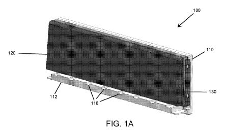
(e.g., glass fibers).
The upper panel may include an elastomeric material. The upper panel surface
may
include surface patterning or roughness to reduce sliding. The upper panel
surface may
include an outer lip along at least one edge for retaining items placed on the
shelf. In
1
CA 03191876 2023-02-14
WO 2022/036161 PCT/US2021/045835
some embodiments, the lip extends along an edge of the upper panel surface
opposite
the back panel.
[0010] The back panel may include a first side recess and a second side
recess. The
shelf panel may include a third side recess and a fourth side recess. The at
least one
fastener may include a first fastener and a second fastener. The first
fastener may be
sized and shaped to occupy the first and third recesses. The second fastener
may be
sized and shaped to occupy the second and fourth recesses. The first and
second
fasteners may be L-shaped (e.g., steel angle braces).
[0011] In some embodiments, the side fasteners fit entirely within the
recesses.
However, in other embodiments, only a portion (e.g., half) of a side fastener
fits within the
recesses of a first shelf assembly and a remaining portion fits within
recesses of a second
shelf assembly. The modular design allows a plurality of shelf assemblies to
be
connected to form a longer shelf system.
[0012] The back panel may include a ledge extending away from the surface
of the
back panel opposite the wall-facing surface. The upper surface of the ledge
and a lower
surface of the shelf panel may include complementary mating features. For
example, the
ledge may include at least one channel and the shelf panel may include at
least one
complementary feature sized and shaped to fit within the at least one channel.
The shelf
panel may also or alternatively include at least one clip and the ledge may
also or
alternatively include at least one recess configured to receive at least one
clip.
[0013] Also disclosed are packaged shelf systems including a container and
within the
container: a back panel comprising a ledge, a first side recess, and a second
side recess;
a shelf panel comprising a non-slip surface, a third side recess, and a fourth
side recess;
a first L-shaped fastener configured to mate resiliently with the first side
recess and the
third side recess; and a second L-shaped fastener configured to mate
resiliently with the
second side recess and the fourth side recess.
[0014] The shelf panel may reside on the ledge, a first straight portion of
the first L-
shaped fastener may extend between the shelf panel and the ledge on a first
side, and a
second straight portion of the second L-shaped fastener may extend between the
shelf
panel and the ledge on a second side.
2
CA 03191876 2023-02-14
WO 2022/036161 PCT/US2021/045835
[0015] In some embodiments, the system further includes at least one base
or bracket
for mounting the shelf system to a wall.
[0016] The back panel may include a wall-facing surface configured to be
slide over
the at least one base or bracket.
[0017] In some embodiments, the at least one base or bracket is visible
through a
transparent window of the container.
[0018] Methods for packing and/or assembling the shelf systems are also
disclosed.
[0019] These and other non-limiting characteristics are more particularly
described
below.
BRIEF DESCRIPTION OF THE DRAWINGS
[0020] The following is a brief description of the drawings, which are
presented for the
purposes of illustrating the exemplary embodiments disclosed herein and not
for the
purposes of limiting the same.
[0021] FIG. 1A is a front perspective view of a shelf system in a shipping
configuration
in accordance with some embodiments of the present disclosure.
[0022] FIG. 1B is a front view of the shelf system of FIG. 1A.
[0023] FIG. 1C is a side view of the shelf system of FIGS. 1A-B.
[0024] FIG. 2 is an exploded view of the shelf system of FIGS. 1A-C.
[0025] FIG. 3 is an exploded view of a shelf system in a mountable
configuration in
accordance with some embodiments of the present disclosure.
[0026] FIG. 4 is a schematic flow chart illustrating an assembly and
mounting method
in accordance with some embodiments of the present disclosure.
[0027] FIG. 5 is a front perspective view of an assembled shelf system in
accordance
with some embodiments of the present disclosure.
[0028] FIG. 6 is a drawing showing bases inserted in opposite orientation
in
accordance with some embodiments of the present disclosure.
[0029] FIG. 7 is a zoomed in view of a rear surface of the back panel
showing an
inserted helper tool in accordance with some embodiments of the present
disclosure.
[0030] FIG. 8 is a drawing of a template sliding into a shelf in accordance
with some
embodiments of the present disclosure.
3
CA 03191876 2023-02-14
WO 2022/036161 PCT/US2021/045835
[0031] FIG. 9 is a flow chart illustrating a process for securing a shelf
assembly to a
wall in accordance with some non-limiting embodiments of the present
disclosure.
DETAILED DESCRIPTION
[0032] The present disclosure may be understood more readily by reference
to the
following detailed description of desired embodiments included therein. In the
following
specification and the claims which follow, reference will be made to a number
of terms
which shall be defined to have the following meanings.
[0033] Unless otherwise defined, all technical and scientific terms used
herein have
the same meaning as commonly understood by one of ordinary skill in the art.
In case of
conflict, the present document, including definitions, will control. Preferred
methods and
materials are described below, although methods and materials similar or
equivalent can
be used in practice or testing of the present disclosure. All publications,
patent
applications, patents, and other references mentioned herein are incorporated
by
reference in their entirety. The materials, methods, and articles disclosed
herein are
illustrative only and not intended to be limiting.
[0034] The singular forms "a," "an," and "the" include plural referents
unless the
context clearly dictates otherwise.
[0035] As used in the specification and in the claims, the term
"comprising" may
include the embodiments "consisting of" and "consisting essentially of." The
terms
"comprise(s)," "include(s)," "having," "has," "can," "contain(s)," and
variants thereof, as
used herein, are intended to be open-ended transitional phrases that require
the presence
of the named ingredients/steps and permit the presence of other
ingredients/steps.
However, such description should be construed as also describing compositions,
mixtures, or processes as "consisting of" and "consisting essentially of" the
enumerated
ingredients/steps, which allows the presence of only the named
ingredients/steps, along
with any impurities that might result therefrom, and excludes other
ingredients/steps.
[0036] Unless indicated to the contrary, the numerical values in the
specification should
be understood to include numerical values which are the same when reduced to
the same
number of significant figures and numerical values which differ from the
stated value by
4
CA 03191876 2023-02-14
WO 2022/036161 PCT/US2021/045835
less than the experimental error of the conventional measurement technique of
the type
used to determine the particular value.
[0037] All ranges disclosed herein are inclusive of the recited endpoint
and
independently combinable (for example, the range of from 2 to 10" is inclusive
of the
endpoints, 2 and 10, and all the intermediate values). The endpoints of the
ranges and
any values disclosed herein are not limited to the precise range or value;
they are
sufficiently imprecise to include values approximating these ranges and/or
values.
[0038] As used herein, approximating language may be applied to modify any
quantitative representation that may vary without resulting in a change in the
basic function
to which it is related. Accordingly, a value modified by a term or terms, such
as "about"
and "substantially," may not be limited to the precise value specified, in
some cases. The
modifier "about" should also be considered as disclosing the range defined by
the absolute
values of the two endpoints. For example, the expression from about 2 to about
4" also
discloses the range from 2 to 4." The term "about" may refer to plus or minus
10% of the
indicated number. For example, "about 10%" may indicate a range of 9% to 11%,
and
"about 1" may mean from 0.9-1.1.
[0039] For the recitation of numeric ranges herein, each intervening number
there
between with the same degree of precision is explicitly contemplated. For
example, for the
range of 6-9, the numbers 7 and 8 are contemplated in addition to 6 and 9, and
for the
range 6.0-7.0, the number 6.0, 6.1, 6.2, 6.3, 6.4, 6.5, 6.6, 6.7, 6.8, 6.9,
and 7.0 are explicitly
contemplated.
[0040] The present disclosure relates to a wall mountable shelf system. The
shelf
system packs flat with insertion places for components for more efficient
shipping and
merchandising. The shelf system is easily assembled using fasteners (e.g., L-
shaped
stainless steel braces) to connect to plastic parts. A wall facing surface of
one of the
plastic parts may be configured to slide over one or more mounting bases or
braces
secured to a wall in advance.
[0041] FIGS. 1A-C illustrates a shipping configuration of a mountable shelf
system
100 in accordance with some embodiments of the present disclosure. As shown,
the
system 100 can be packed in a thin container due to the shapes of the
components. For
example, a system 100 with an assembled depth of 80 mm may have dimensions of
100
CA 03191876 2023-02-14
WO 2022/036161 PCT/US2021/045835
mm x 310 mm x 35 mm. The system 100 includes a back panel 110, a shelf panel
120,
and fasteners 130. The back panel includes a ledge 112 with recesses 118. In
the
shipping configuration, the shelf panel 120 fits on the ledge 112.
[0042] FIG. 2 is an exploded view of the system of FIGS. 1A-C. The system
200
includes a back panel 210 with a ledge 212, mounting braces or brackets 240,
shelf panel
220, and L-shaped fasteners 230. In this shipping configuration, the shelf
panel 220
resides of the ledge 212 and one of the straight portions of each fastener 230
fits between
the panels 210, 220. The shelf panel 220 includes lower layer 222 and upper
layer 224.
The lower layer 222 includes a clip 226 for mating with a recess in the ledge
212 (not
shown).
[0043] FIG. 3 is an exploded view of a mountable shelf system 300 in a
mountable
configuration. The system 300 includes a back panel 310, a shelf panel 320,
and
fasteners 330. The back panel 310 includes a ledge 312 having a plurality of
channels
318 and a recess 316. The back panel 310 further includes a side recess 311
(and a
similar recess on the opposite side is not visible). The shelf panel 320
includes a lower
layer 322 and an upper layer 324. The lower layer 322 includes a clip 326
which is
complementary to the recess 316 in at least one of the shipping and mounting
configurations. The lower layer 322 may further include features (not shown)
which are
complementary to the channels 318. The upper layer 324 may include one or more
features to reduce the likelihood of items stored on the shelf from rolling or
sliding off.
The features may include surface patterning or roughness for increased
friction and/or a
lip 328 extending from a top surface thereof. The surface may be a non-slip
grip surface.
The lower layer 322 further includes a side recess 321 (and a similar recess
on the
opposite side is not visible). It is also possible for the side recess 321 to
be located in the
upper layer 324 or between the lower and upper layers 322, 324. These recesses
are
sized to receive the L-shaped fasteners 330. These fasteners 330 hold the
panels
together. In the mounting configuration, it is possible to use an adhesive
composition
with the fasteners and/or at an interface between the panels. It is also
possible for the
shelf panel to be a unitary one-piece structure instead of a multi-piece
structure.
[0044] The fasteners may include a high strength material such as a metal
(e.g., steel).
6
CA 03191876 2023-02-14
WO 2022/036161 PCT/US2021/045835
[0045] The lower layer and the back panel may include the same or different
plastic
materials (optionally reinforced with a filler material such as glass fibers).
Non-limiting
examples of plastic materials include polyamides, polycarbonates, polyolefins
(e.g.,
polyethylene, polypropylene), acrylonitrile butadiene styrene (ABS) polymers,
polyethylene terephthalate (PET), polybutylene terephthalate (PBT), and
polyvinyl
chloride (PVC).
[0046] The upper layer may include an elastomeric material. Non-limiting
examples
of elastomeric materials include polyisoprene, polybutadiene, chloroprene
rubber, butyl
rubber, styrene-butadiene rubber, nitrile rubber, ethylene propylene rubber
(EPM),
ethylene propylene diene rubber (EPDM), epichlorohydrin rubber, polyacrylic
rubber,
silicone rubber, fluorosilicone rubber, fluoroelastomers, perfluoroelastomers,
polyether
block amides, and chlorosulfonated polyethylene.
[0047] FIG. 4 illustrates an embodiment of a method for assembling and
mounting the
shelf system. In step 1, the shelf panel is clipped onto the ledge. In step 2,
the L-shaped
fasteners are inserted into the recesses to secure the panels together. In
step 3, the shelf
system is mounted onto the wall.
[0048] FIG. 5 illustrates an assembled shelf system 400. The system 400
includes
back panel 410 and shelf panel 420 fastened together with fasteners 430. The
shelf panel
420 includes a lower plastic layer 422 and an upper elastomeric layer 424.
[0049] FIG. 6 is a drawing of the rear surface of a back panel with
mounting bases.
The bases are inserted in the opposite orientation so that they're held in
place for
packaging. The packaging may include transparent windows so that these bases
are
visible.
[0050] FIG. 7 is a zoomed in view of a portion of the back panel showing an
insertion
location for a helper tool.
[0051] FIG. 8 is a photograph showing a template being inserted into a
shelf.
[0052] In some embodiments, the fasteners fit fully within the side
recesses of the
plastic parts. However, in other embodiments, the fasteners extend partially
out (e.g.,
50%) of the recesses. In these embodiments, a plurality of modular shelf units
may be
connected to form the shelf system. For example, two shelf modules may be
connected
using an L-shaped fastener to form a longer shelf system. It is possible to
include smaller
7
CA 03191876 2023-02-14
WO 2022/036161 PCT/US2021/045835
fasteners for the ends of the shelf system and larger fasteners securing
adjacent modules
together. Where multiple shelf modules are connected to form a longer shelf
system,
each individual module may independently have the same length or a different
length
compared to every other module. Modules with different lengths may enhance the
customizability of the overall length of the shelf system.
[0053] Non-limiting examples of mounting brackets and how they may be
secured to
walls (optionally using templates) are described in WO 2019/141969A1 to
Woolman
published July 25, 2019 and U.S. Pat. No. 10,143,316 to Will etal. issued
December 4,
2018. The contents of these documents are incorporated by reference herein in
their
entireties.
[0054] The upper and lower layers of the shelf panel may be permanently
secured to
each other. In other embodiments, these layers are detachably attached. For
example,
the upper elastomeric layer may be removable and could be replaced with
another
elastomeric layer having a different color and/or texture.
[0055] The elastomeric material may be a thermoplastic elastomer. Non-
limiting
examples include styrenic block copolymers, thermoplastic
polyolefinelastomers,
thermoplastic vulcanizates, thermoplastic polyurethanes, thermoplastic
copolyester, and
thermoplastic polyamides.
[0056] The elastomeric material may be continuous or discontinuous on the
surface.
For example, the elastomeric material may be present in strips oriented
perpendicular to
the length of the shelf, parallel to the length of the shelf, or at an
intermediate angle.
[0057] The system may include two bases per 12" of shelf length in some
embodiments.
[0058] The bases may include an adhesive on at least one of a wall-facing
surface
and a back panel-facing surface.
[0059] Each base may include a level (e.g., a bubble level). Alternatively
or
additionally, a template used to achieve correct spacing between adjacent
bases may
include a level (e.g., a bubble level).
[0060] The template may include holes or transparent portions such that
desired areas
of the base are visible and/or readily accessible. For example, at least one
level (e.g., a
bubble level) of the base may be visible through the template to assist in
applying the
8
CA 03191876 2023-02-14
WO 2022/036161 PCT/US2021/045835
base to the wall properly. Alternatively or additionally, holes for screws,
pins, or other
fasteners in the base may be accessible through the template.
[0061] A process for securing the bases to a wall may include associating a
template
with a plurality (e.g., 2) bases, positioning the template at the wall,
inserting fasteners
through apertures in the template and bases to secure the bases to the wall,
and removing
the template (e.g., by sliding it over the bases). The shelf can then be
attached to the
wall (e.g., by sliding it over the bases).
[0062] The template may be aligned with a top surface of the base, a bottom
surface
of the base, or both the top and bottom surfaces of the base.
[0063] The template may be aligned with a top surface of the shelf
assembly, a bottom
surface of the shelf assembly, or both the top and bottom surfaces of the
shelf assembly.
[0064] Two or more shelf assemblies may be attached to a wall at the same
time by
joining the assemblies together with a joiner piece (e.g., L-shaped fastener).
The joined
assemblies can then be installed on the wall as a single unit.
[0065] When the fasteners are L-shaped, they may be cut from a flat metal
element
(i.e., 2-dimensional) or cut from a bent metal element (i.e., 3-dimensional).
[0066] A process for installing multiple shelf assemblies can include using
a template
to align a first base with a second base, removing the template and shifting
it over to align
the second base with a third base, etc. Use of the template may assist in
achieving
correct spacing and alignment.
[0067] FIG. 9 is a flow chart illustrating a process 501 for assembling and
securing a
shelf assembly to a wall in accordance with some non-limiting embodiments of
the
present disclosure. The process 501 includes assembling the shelf assembly
550,
inserting braces 552, removing release liners from bases to expose an adhesive
554,
adhering the bases to the wall 556, inserting pins or other fasteners into the
wall through
holes in the base 558, removing a template from the bases and applying the
shelf
assembly to the bases 560, and optionally applying a further shelf assembly by
repeating
these elements 562.
[0068] The assembling 550 includes joining the back panel and shelf panel.
In some
embodiments, the assembly is configured such that a click is audible when the
panels are
properly joined.
9
CA 03191876 2023-02-14
WO 2022/036161 PCT/US2021/045835
[0069] The braces may be inserted 552 through a rear surface of the back
panel and
extend into the shelf panel. The braces may be L-shaped. In some embodiments,
the
braces are not visible through the side surface(s) of the back panel and/or
the shelf panel.
In other embodiments, the braces are visible through the side surface(s). The
braces
may or may not extend through the side surface(s) (e.g., to allow an
additional shelf
assembly to be connected and lengthen the shelf).
[0070] The release liners may be removed 554 while the bases are in the
template to
expose an adhesive (e.g., a permanent adhesive).
[0071] Next, the bases are adhered to the wall 556 (e.g., a clean drywall
surface).
They may be adhered while a bubble level on the template is utilized for
proper alignment.
For example, the bases and/or template in the region of the bases may be
pressed firmly
for about 30 seconds.
[0072] Fasteners are inserted 558 into the wall through holes in the bases.
The
fasteners may be pins (e.g., six pins per base). In some embodiments, a
magnetic pin
helper is used to insert the pins. The fasteners used may depend on the wall
surface.
For example, screws may be utilized for a wooden surface.
[0073] The template is removed and the shelf assembly is applied to the
bases 560.
In other embodiments, the shelf assembly may be applied over the bases and
template
without removal of the template. The application may involve sliding the shelf
assembly
over the bases in a vertical direction (e.g., over the top) or a horizontal
direction (e.g.,
from left to right or right to left).
[0074] Optionally, these steps are repeated 562 to apply additional shelf
assemblies
(e.g., to lengthen the shelf).
[0075] It will be appreciated that variants of the above-disclosed and
other features
and functions, or alternatives thereof, may be combined into many other
different systems
or applications. Various presently unforeseen or unanticipated alternatives,
modifications,
variations or improvements therein may be subsequently made by those skilled
in the art
which are also intended to be encompassed by the following claims.