Note: Descriptions are shown in the official language in which they were submitted.
CA Application
CPST Ref: 41049/00001
I DOCK DOOR ASSEMBLY
2 CROSS REFERENCE TO RELATED APPLICATION
3 [01] The present application claims priority to U.S. Application No.
63/322,497 filed on March
4 22, 2022, which is hereby incorporated fully by reference for any non-
limiting purposes.
l'ECHNICAL FIELD
6 [02] In a principal aspect the present invention relates to a dock door
assembly and method of
7 assembly for a multi-section dock door assembly and commercial sectional
doors for warehouses
8 and other types of buildings.
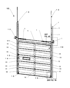
9 BACKGROUND
[03] Various types of buildings, such as warehouses with docks may include
openings with
11 doors for ingress and egress comprised of multiple, horizontal sections
joined together by hinges
12 and mounted on tracks to guide the articulating door sections between a
closed position and an
13 open position.
14 [04] Warehouses and warehousing storage continue to grow with both new and
retrofit
requirements. With today's fast paced shipping world with next day and 2-day
deliveries, there is
16 a continued need for more warehouses and more dock doors. Garage door
service providers are
17 looking for faster and more cost effective ways to install dock doors.
Dock door installation comes
18 at a price, such as time and money. An ideal dock door installation
method would include minimal
19 trips to the dock door opening and minimal parts to save installation
time and money.
SUMMARY
21 [05] Briefly, the present invention comprises a unique and novel dock
door assembly and
22 method of assembly for a multi-sections dock door assembly and
commercial sectional doors for
23 warehouses and other types of buildings.
1
CPST Doc: 480358.1
Date Recue/Date Received 2023-03-09
CA Application
CPST Ref: 41049/00001
1 [06] In a first aspect, a dock door assembly for use in a dock door
opening in a warehouse may
2 comprise a pair of tracks; a multiple, horizontal section door; a spring
shaft assembly; a pair of
3 headplates; and a pair of door cables and a pair of corner cable
attachments. The pair of tracks
4 may include each track configured to be attached to a wall along opposing
lateral sides of the dock
door opening. Each track may comprise a vertical roller track and a clip angle
wall plate to attach
6 each vertical roller track to the wall. The multiple, horizontal section
door may be characterized
7 by a vertical height when closed and mounted on the pair of tracks. The
door may be moveable
8 on the vertical roller tracks between an open and a substantially
vertical closed position. The door
9 may include a plurality of horizontal sections. The spring shaft assembly
may be located adjacent
and above a top of the door opening at approximately 16-1/2 inches above
header height. The
11 spring shaft assembly may include a torsion shaft, a pair of cable drums
with each cable drum
12 located near an end of the torsion shaft, at least one counterbalance
torsion spring extending along
13 the torsion shaft, and at least one torque bracket. The pair of
headplates may include one headplate
14 fastened to each of the clip angle wall plates and vertical track. Each
headplate may be located at
the opposing lateral sides of the door opening. The headplate may have a U-
shaped opening to
16 receive each end of the torsion shaft. The pair of door cables and the
pair of corner cable
17 attachments may connect each door cable to each of the cable drums. The
door cable may have a
18 first end attached to the cable drum and a second end attached to the
corner cable attachment. The
19 corner cable attachment may be located on an interior of the dock door
and on a lowermost
horizontal section of the dock door.
21 [07] In other embodiments, the door dock assembly may further include a
section cleat that
22 includes a wind lock feature that comprises a wall cleat and a door
cleat. The wall cleat and the
23 door cleat may cooperatively engage and secure the dock door for
windload resistance. The wall
24 cleat may be attached to the clip angle wall plate and the door cleat
may be attached to two of the
horizontal sections. The wall cleat may comprise a wall cleat extension arm
that extends from a
26 wall cleat support plate attached to the clip angle wall plate. The door
cleat may comprise a door
27 cleat extension arm that extends from the door cleat support plate
attached to two of the horizontal
2
CPST Doc: 480358.1
Date Recue/Date Received 2023-03-09
CA Application
CPST Ref: 41049/00001
1 sections. The wall cleat extension arm and the door cleat extension arm
may cooperate and engage
2 with each other to keep the dock door secure for windload resistance.
3 [08] In other embodiments, the dock door assembly may further include an
interior lock that
4 comprises a slide bar attached to one of the horizontal sections. The
slide bar may slide between
an extended position and a compressed position. When the slide bar is in the
compressed position,
6 the slide bar may engage with a strike plate attached to the vertical
track and locks the dock door
7 in a closed position. When the slide bar is in the extended position, the
slide bar may be disengaged
8 with the strike plate and the dock door is unlocked. The slide bar may be
approximately 9 inches
9 long.
[09] Additionally, in other embodiments, two of the plurality of horizontal
sections may be
11 fastened together by a section center plate and two section end cleats
using one or more fasteners,
12 such as four fasteners. Further, each of the headplates may extend
perpendicular to the wall. The
13 U-shaped opening may be angled upward to ensure the torsion shaft sets
into the opening and
14 remains in the opening, thereby allowing the spring shaft assembly to be
front loaded and front
mounted on the headplate and the pair of tracks and wall. The upward angled U-
shaped opening
16 may allow the spring shaft assembly to rest in place while the spring
shaft assembly is being bolted
17 to the headplate.
18 [10] Further, in other embodiments, the dock door assembly may comprise
one or more
19 outboard shaft support plates mounted to the wall to support the spring
shaft assembly and the
torsion shaft. The one or more outboard shaft support plates may include a
wall bracket attached
21 to the wall and a support arm extending perpendicularly from the wall
bracket to receive and hold
22 one or more of the ends of the torsion shaft. The outboard shaft support
plates may limit the
23 deflection of the torsion shaft in the middle of the torsion assembly,
with one outboard shaft
24 support plate on each side of the headplate. The outboard shaft support
plates may be only required
on doors with a weight of the spring shaft assembly and the torsion shaft
great enough to cause
26 substantial deflection.
3
CPST Doc: 480358.1
Date Recue/Date Received 2023-03-09
CA Application
CPST Ref: 41049/00001
1 1111 In another aspect, a dock door assembly kit for installation and
assembly in a dock door
2 opening of a warehouse, the dock door assembly kit may comprise: a track
assembly configured
3 to be attached to a wall; a plurality of pre-assembled door panels; a
spring shaft assembly; and a
4 hardware carton comprising components required for final installation of
the dock door assembly.
The track assembly may include a pair of pre-assembled vertical tracks with
each of the pre-
6 assembled vertical tracks comprising a vertical roller track, a clip
angle wall plate attached to the
7 vertical roller track with a plurality of track clips, and a headplate.
The headplate may have a U-
8 shaped opening and may be attached to the clip angle wall plate and
vertical track. Each of the
9 pre-assembled vertical tracks may be configured to attach to opposing
lateral sides of a door
opening. Each pre-assembled door panel may comprise a plurality of horizontal
door sections pre-
11 assembled together with one or more section center plates and one or
more section end cleats. The
12 plurality of pre-assembled door panels connected together may define a
multiple, horizontal
13 section door characterized by a vertical height when closed and mounted
on the track assembly.
14 The door may be configured to be moveable on the track assembly between an
open and a
substantially vertical closed position. The spring shaft assembly may include
a torsion shaft with
16 pre-assembled components defined by a pair of cable drums with each
cable drum located at an
17 end of the torsion shaft, at least one counterbalance torsion spring
extending along the torsion
18 shaft, and at least one torque bracket adjacent the at least one
counterbalance torsion spring. The
19 ends of the torsion shaft may be configured to set in the U-shaped
opening of the headplates. The
components may include: one or more door cables, an interior lock, a door
handle, one or more
21 section center plates, one or more edge hinge assemblies, two corner
cable brackets, two top
22 fixtures, a plurality of rollers, a step plate, and a plurality of
fasteners for the component
23 installation.
24 [12] In other embodiments of the dock door assembly kit, the plurality
of pre-assembled door
panels may include a top door panel and a bottom door panel. The top door
panel may be
26 comprised of two or three horizontal sections pre-assembled together
with one section center plate
27 and two section end cleats. The bottom door panel may be comprised of
two or three horizontal
4
CPST Doc: 480358.1
Date Recue/Date Received 2023-03-09
CA Application
CPST Ref: 41049/00001
1 sections pre-assembled together with two section center plates and four
section end cleats. In yet
2 a further embodiment of the dock door assembly kit, the hardware carton
may include one or more
3 outboard shaft support plates configured to be mounted to the wall to
support the spring shaft
4 assembly and the torsion shaft. The one or more outboard shaft support
plates may include a wall
.. bracket configured to be attached to the wall and a support arm extending
perpendicularly from
6 the wall bracket configured to receive and hold one or more of the ends
of the torsion shaft.
7 BRIEF DESCRIPTION OF THE DRAWING
8 [13] The foregoing summary, as well as the following detailed description
of exemplary
9 embodiments, is better understood when read in conjunction with the
accompanying drawings,
which are included by way of example, and not by way of limitation with regard
to the claimed
11 invention. In the detailed description which follows, reference will be
made to the drawing
12 comprised of the following figures:
13 [14] FIG.1 is a perspective exterior view of a typical warehouse
arrangement with various dock
14 locations and dock doors in accordance with aspects of the invention;
[15] FIG. 2A is an isometric interior view sectional dock door assembly in
accordance with
16 aspects of the invention;
17 [16] FIG. 2B is a front interior view of the dock door assembly from
FIG. 2A in accordance
18 with aspects of the invention;
19 [17] FIG. 2C is a top interior view of the dock door assembly from FIG.
2A in accordance with
aspects of the invention;
21 [18] FIG. 2D is a side interior view of the dock door assembly from FIG.
2A in accordance
22 with aspects of the invention;
5
CPST Doc: 480358.1
Date Recue/Date Received 2023-03-09
CA Application
CPST Ref: 41049/00001
1 [19] FIGS. 3A and 3B are side views of a track assembly of the dock door
assembly from FIG.
2 2A in accordance with aspects of the invention;
3 [20] FIG. 4A is a side perspective view of a spring shaft assembly of the
dock door assembly
4 from FIG. 2A in accordance with aspects of the invention;
[21] FIG. 4B is a perspective view of the spring shaft assembly taken from
FIG. 2A of the dock
6 .. door assembly in accordance with aspects of the invention;
7 [22] FIGS. 5A and 5B are top views of various embodiments of the spring
shaft assembly of
8 the dock door assembly from FIG. 2A in accordance with aspects of the
invention;
9 [23] FIGS. 6A and 6B are various views of a headplate from the dock door
assembly from FIG.
2A in accordance with aspects of the invention;
11 [24] FIG. 6C is a side perspective view of a torque bracket from the
dock door assembly from
12 FIG. 2A in accordance with aspects of the invention;
13 [25] FIG. 6D is a side perspective view of an outboard shaft support
plates from the dock door
14 assembly from FIG. 2A in accordance with aspects of the invention;
.. [26] FIGS. 7A and 7B are front perspective views of a cable assembly of the
dock door
16 assembly from FIG. 2A in accordance with aspects of the invention;
17 [27] FIG. 8A is a side perspective view of a windload lock from the dock
door assembly from
18 FIG. 2A in accordance with aspects of the invention;
19 [28] FIG. 8B is a top view of the windload lock from the dock door
assembly from FIG. 2A in
accordance with aspects of the invention;
21 [29] FIGS. 8C and 8D are various views of a wall cleat from the windload
lock from the dock
22 door assembly from FIG. 2A in accordance with aspects of the invention;
6
CPST Doc: 480358.1
Date Recue/Date Received 2023-03-09
CA Application
CPST Ref: 41049/00001
1 [30] FIGS. 8E-8G are various views of a door cleat from the windload lock
from the dock door
2 assembly from FIG. 2A in accordance with aspects of the invention;
3 [31] FIGS. 8H and 81 are various views of another wall cleat from the
windload lock from the
4 dock door assembly from FIG. 2A in accordance with aspects of the
invention;
[32] FIGS. 8J and 8K are various views of another door cleat from the windload
lock from the
6 dock door assembly from FIG. 2A in accordance with aspects of the
invention;
7 [33] FIGS. 9A-9D are various views of an interior lock from the dock door
assembly from FIG.
8 2A in accordance with aspects of the invention;
9 [34] FIG. 9E is a component and installation view of the interior lock
from the dock door
assembly from FIG. 2A in accordance with aspects of the invention;
11 [35] FIG. 10A is a front view of pre-assembled door panels from the dock
door assembly from
12 FIG. 2A in accordance with aspects of the invention;
13 [36] FIG. 10B are front perspective views of a pre-assembled track
assembly, a pre-assembled
14 spring shaft assembly, and a hardware carton for the dock door assembly
from FIG. 2A in
accordance with aspects of the invention;
16 [37] FIGS. 11A and 11B are various views of a racking to ship one or
more pre-assembled
17 spring shaft assemblies for the dock door assembly from FIG. 2A in
accordance with aspects of
18 the invention; and
19 [38] FIG. 12 is a perspective view of a racking to ship one or more pre-
assembled door panels
for the dock door assembly from FIG. 2A in accordance with aspects of the
invention.
21 [39] The reader is advised that the attached drawings are not
necessarily drawn to scale.
7
CPST Doc: 480358.1
Date Recue/Date Received 2023-03-09
CA Application
CPST Ref: 41049/00001
1 DETAILED DESCRIPTION OF EMBODIMENTS
2 [40] In the following description of various examples of the invention,
reference is made to the
3 accompanying drawings, which form a part hereof, and in which are shown
by way of illustration
4 various example structures, systems, and steps in which aspects of the
invention may be practiced.
It is to be understood that other specific arrangements of parts, structures,
example devices,
6 systems, and steps may be utilized and structural and functional
modifications may be made
7 without departing from the scope of the present invention. Also, while
the terms "top," "bottom,"
8 "front," "back," "side," and the like may be used in this specification
to describe various example
9 features and elements of the invention, these terms are used herein as a
matter of convenience,
e.g., based on the example orientations shown in the figures. Nothing in this
specification should
11 be construed as requiring a specific three-dimensional orientation of
structures in order to fall
12 within the scope of this invention.
13 [41] Dock doors are an important piece to the warehouse and shipping
market. Referring to
14 FIG. 1, there is depicted a typical warehouse arrangement 10 with
various dock locations and dock
doors 110. The dock door assembly may be utilized for commercial sectional
doors also. The
16 dock door assembly might include minimal parts, such as pre-assembled door
panels; pre-
17 assembled clip angle track, headplates, and brackets; pre-assembled
spring shaft assembly with
18 counterbalance and drums set on the shaft. The dock doors 110 may be
various sizes known and
19 used in the art, such as 8'-2", 8'-4", 9'-2", or 9'-4" wide and 8', 9',
or 10' high. The dock doors
110 may be various models and construction, such as 20 gauge steel, 24 gauge
steel, 26 gauge
21 steel, 2" thick sandwich polystyrene, or 2" thick polyurethane. A dock
door assembly may include
22 dock door tracks that may be various sizes, such as for example 2" and
3" tracks. The dock door
23 assembly 100 may include windows, locks, and/or step plates. Other dock
door sizes, dock door
24 models and construction, and track sizes may be utilized without
departing from this invention.
[42] Referring to FIG. 2A, there is depicted in an isometric view a new
sectional dock door
26 assembly 100. FIG. 2B depicts a front view of the dock door assembly
100. FIG. 2C depicts a
8
CPST Doc: 480358.1
Date Recue/Date Received 2023-03-09
CA Application
CPST Ref: 41049/00001
1 top view of the dock door assembly 100. FIG. 2D depicts a side view of
the dock door assembly
2 100. The dock door assembly 100 and dock door assembly kits (as detailed
and described in
3 reference to FIGS. 10A and 10B) may be installed quicker than equivalent
prior art versions. For
4 example, prior art dock door installation takes approximately 60-75
minutes using two installers.
The dock door assembly 100 and dock door assembly kit installation of the
present invention may
6 take approximately 30 minutes and even as low as 24 minutes using two
installers.
7 [43] The dock door assembly 100 may include a multiple section,
horizontal section dock door
8 110; a track assembly 120 configured to be attached to a wall; a torsion
spring assembly 150 to
9 raise and lower the dock door 110 along the track assembly 120; and a
cable assembly 160 attached
to the spring shaft assembly 150 with the dock door 110.
11 [44] The dock door 110 may be made up of a series of horizontal sections
111, 112, 113, 114,
12 115. The horizontal sections 111, 112, 113, 114, 115 may be connected by
section center plates
13 116 and section end cleats 118 using one or more fasteners. The section
center plates 116 may be
14 a flat plate without a pivoting hinge as utilized in prior art. The
section end cleats 118 may be
"L"-shaped plates with holes and fasteners. The section end cleats 118 may be
utilized to allow
16 for both reduced number of edge hinges and the packaging of multiple pre-
assembled panels
17 together. The section center plates 116 and the section end cleats 118
provide a clean, simple, and
18 less moving parts for installation and operation. The horizontal
sections 111, 112, 113, 114, 115
19 may be of different construction, materials and combinations of
materials. For example, the
section 113 depicted in FIGS. 2A and 2B includes a window 130. The composition
and
21 construction of the various sections thus provide a door construction
which may vary in terms of
22 materials, size, and weight.
23 1451 The composite arrangement of the horizontal sections 111, 112,
113, 114, 115 are depicted
24 from the inside view of the door construction as arranged to provide an
access opening upon raising
the array of composite sections upwardly guided by first and second multi-
sectioned track
26 assemblies 120 positioned inside of a building such as a warehouse or
garage. Each of the track
9
CPST Doc: 480358.1
Date Recue/Date Received 2023-03-09
CA Application
CPST Ref: 41049/00001
1 assemblies 120 may be attached to a wall along opposing lateral sides of
the dock door opening.
2 Each of the track assemblies 120 may include a clip angle wall plate 122,
a plurality of track clips
3 124, a weather seal 125, and a vertical track 126 which guides wheels or
rollers attached to the
4 opposing lateral sides of the horizontal sections 111, 112, 113, 114, 115
on the opposing lateral
sides thereof to guide the sections upwardly along the vertical track 126.
6 [46] The dock door 110 may be raised or lowered by means of a spring
shaft assembly 150. The
7 spring shaft assembly 150 may be rotationally mounted above the top
horizontal section 111 on a
8 headplate 142 attached to the track assembly 120. Optionally, one or more
outboard shaft support
9 plates 144 may be mounted to the wall to provide support to the spring
shaft assembly 150. The
spring shaft assembly 150 may include a torsion shaft 152, one or more torque
brackets 154, one
11 or more cable drums 156, one or more bearings, and one or more torsion
springs 158. The torsion
12 springs 158 may provide a means to counterbalance the weight of the door
construction. The cable
13 drum 156 may be mounted on opposite ends of the torsion shaft 152 and be
attached to the torsion
14 shaft 152 to rotate coaxially therewith.
[47] A cable assembly 160 may be attached to the spring shaft assembly 150
with the dock door
16 110. The cable assembly 160 may include a door cable 162 and a corner
cable bracket 164
17 connecting the door cable 162 to the dock door 110. Each cable drum 156
may receive the door
18 cable 162 which is cooperative respectively with the cable drum 156. One
end of each door cable
19 162 may be attached, respectively, to the cable drum 156 associated
therewith. Each door cable
162 may wind or unwind from the associated cable drum 156 upon rotation of the
torsion shaft
21 142. The opposite end of each door cable 162 is attached to the lowest
or lower horizontal section
22 115 at the corner cable bracket 164. Thus, in order to raise the dock
door 110 from the closed
23 position as depicted in FIGS. 2A and 2B, the torsion shaft 152 may be
rotated appropriately to
24 wind the appropriate door cable 162 on the appropriate drum 156. The
winding and unwinding
operation may involve rotating the torsion shaft 152 in the appropriate
rotational sense relative to
26 raising and lowering the dock door 110. Thus, movement of the dock door
110 may be affected
CPST Doc: 480358.1
Date Recue/Date Received 2023-03-09
CA Application
CPST Ref: 41049/00001
1 by manually raising or lifting the spring counterbalanced dock door 110.
One or more door cables
2 162, such as two door cables 162, may be utilized.
3 [48] The torsion shaft 152 may be rotationally driven, for example, by an
electric motor (not
4 shown). Such opening of the dock door 110 may thus move the dock door 110
electronically using
the electric motor from the closed position to an open position.
6 [49] FIGS. 3A and 3B illustrate a side view of the track assembly 120. As
illustrated in FIGS.
7 3A and 3B, the track assembly 120 may include a clip angle wall plate
122, a plurality of track
8 clips 124, a weather seal 125, and a vertical track 126. The weather seal
125 may snap onto an
9 edge of the clip angle wall plate 122. The clip angle wall plate 122 may
be configured to mount
to a wall of the building. The clip angle wall plate 122 may be defined by an
"L" shape. The
11 plurality of track clips 124 may connect the vertical track 126 to the
clip angle wall plate 122 using
12 one or more fasteners. As illustrated in FIG. 3A, the plurality of track
clips 124 may include
13 approximately eight track clips. Other numbers of track clips 124 may be
utilized to attach the
14 vertical track 126 to the clip angle wall plate 122, which may be based
on and vary with the height
of the door. As depicted in FIG. 3A, the vertical track 126 may be slightly
angled away from the
16 wall using the track clips 124. As will be explained and detailed
further, the track assembly 120
17 may be pre-assembled to create a one-piece track style to save
installation time. The track
18 assembly 120 may also include type "A" track graduation so that the
track assembly 120 may be
19 installed tight to the wall. The track assembly 120 may be sized for
various widths known and
used in the art, for example, 2" tracks and 3" tracks. Other track
sizes/widths may be used without
21 departing from this invention. Additionally, the headplate 142 may be
pre-assembled with the
22 track assembly 120.
23 [50] FIGS. 4A and 4B illustrate views of and the spring shaft assembly
150 mounted on the
24 headplate 142. FIG. 4A illustrates a spring shaft assembly 150 without
an outboard shaft support
plate 144. FIG. 4B illustrates the spring shaft assembly 150 with an outboard
shaft support plate
26 144 mounted to the wall to support the torsion shaft 152. The outboard
shaft support plate 144
11
CPST Doc: 480358.1
Date Recue/Date Received 2023-03-09
CA Application
CPST Ref: 41049/00001
1 may be required to reduce deflection of the torsion shaft 152 if the
additional weight of the torsion
2 springs 158 is over a pre-determined weight.
3 1511 As illustrated in FIGS. 4A and 4B, the spring shaft assembly 150 may
include a torsion
4 shaft 152, one or more torque brackets 154, one or more cable drums 156,
one or more bearings,
and one or more torsion springs 158. As illustrated in FIGS. 4A and 4B, the
headplate 142 may
6 be connected to and/or fastened to the track assembly 120 and
specifically the clip angle wall plate
7 122 and the vertical track 126 using one or more fasteners. The headplate
142 may extend
8 perpendicular to the wall. The headplate 142 may include a U-shaped
opening 143 for receiving
9 each end of the torsion shaft 152. The U-shaped opening 143 may be angled
upward to ensure
that the torsion shaft 152 sets into the opening 143 and remains in the
opening 143. The spring
11 shaft assembly 150 may be front loaded and front mounted on the
headplate 142, the track
12 assembly 120, and the wall. As will be explained and detailed further,
the spring shaft assembly
13 150 may be pre-assembled so that the entire spring shaft assembly 150
can be set into the headplate
14 142 and bolted into place to save installation time.
1521 Additionally, as illustrated in FIGS. 4A and 4B, the spring shaft
assembly 150 may be
16 located approximately 6 inches to 48 inches above the header height
above the top horizontal
17 section 111 of the dock door 110. In another embodiment, the spring
shaft assembly 150 may be
18 located approximately 12 inches to 40 inches above the header height
above the top horizontal
19 section 111 of the dock door 110. In another embodiment, the spring
shaft assembly 150 may be
located approximately 16-1/2 inches above the header height above the top
horizontal section 111
21 of the dock door 110. In other prior art dock door assemblies, the
spring shaft assembly is located
22 approximately 8-12 feet above the header height to avoid the
interference between the dock door
23 and the traditional A-frame mounting for the torsion spring 158 and
shaft 152. Moving the spring
24 shaft assembly 150 location down to the header height above the top
horizontal section 111 of the
dock door 110 allows for easier installation with safer working conditions by
working at
26 approximately twelve feet high instead of approximately 20-24 feet in
the air as with prior art dock
27 door assemblies.
12
CPST Doc: 480358.1
Date Recue/Date Received 2023-03-09
CA Application
CPST Ref: 41049/00001
1 [53] FIGS. 5A and 5B illustrate top views of two exemplary spring shaft
assemblies 150. The
2 spring shaft assembly 150 in FIG. 5A includes one torsion spring 158
located on one end of the
3 torsion shaft 152. The spring shaft assembly 150 in FIG. 5B includes two
torsion springs 158 with
4 one torsion spring 158 located on each of the ends of the torsion shaft
152. Various sizes and
lengths of springs 158 may be utilized with the spring shaft assembly 150
depending on the weight
6 and size of the dock door 110.
7 [54] FIGS. 6A-6D illustrate various views of components of the spring
shaft assembly 150.
8 FIGS. 6A and 6B illustrate a front view and a perspective view of the
headplate 142. As illustrated
9 in FIGS. 6A and 6B, the headplate 142 includes a U-shaped opening 143.
The headplate 142 may
also include various slots and/or holes 145 for attaching to the clip angle
wall plate 122 and the
11 vertical track 126. The headplate 142 may also include locking holes 146
at the arms of the
12 opening 143 to hold the torsion shaft 152 in place in the U-shaped
opening 143 on the headplate
13 142 using one or more fasteners.
14 [55] FIG. 6C illustrates a perspective view of the torque bracket 154.
The torque bracket 154
may include two main holes 154A to receive and hold the torsion shaft 152 next
to the torsion
16 spring 158.
17 [56] FIG. 6D illustrates a perspective view of the outboard shaft
support plate 144. As stated
18 above, the outboard shaft support plate 144 may be optionally mounted to
the wall to support the
19 spring shaft assembly 150 and the torsion shaft 152. The outboard shaft
support plate 144 may be
required if the additional weight of the torsion springs 158 is over a pre-
determined weight. The
21 outboard shaft support plate 144 may include a wall bracket 147 and a
support arm 148 extending
22 perpendicular to the wall bracket 147. The support arm 148 may include a
slot 149 to receive the
23 ends of the torsion shaft 152. The outboard shaft support plate 144 may
include various holes
24 and/or slots to attach to the wall using one or more fasteners. The
outboard shaft support plate 144
may also include various holes and/or slots to hold/lock the torsion shaft 152
in place within the
26 slot 149 using one or more fasteners. The spring shaft assembly 150 may
also include one or more
13
CPST Doc: 480358.1
Date Recue/Date Received 2023-03-09
CA Application
CPST Ref: 41049/00001
1 bearings with set screws to help support the load, and allow rotational
or sliding motion of the
2 spring shaft assembly 150.
3 [57] FIGS. 7A and 7B illustrate a cable assembly 160 that may be attached
to the spring shaft
4 assembly 150 with the dock door 110. FIG. 7A illustrates a front view of
the cable assembly 160.
FIG 7B illustrates a perspective front view of the cable assembly 160 from
FIG. 2A. The cable
6 assembly 160 may include a door cable 162 and a corner cable bracket 164
connecting the door
7 cable 162 to the dock door 110. The corner cable bracket 164 may be
located at the lowest or
8 lower horizontal section 115. The corner cable bracket 164 may include a
door cable pick-up 166
9 to connect the door cable 162 to the corner cable bracket 164. The door
cable 162 may be attached
to the door cable pick-up 166 by various methods known and used in the art.
The door cable pick-
11 up 166 may be located at the front of the dock door 110. The door cable
pick-up 166 may be
12 repositioned from prior art versions. This repositioning and locating
the door cable pick-up 166
13 at the front of the door eliminates any cable interference during door
operation from the
14 repositioning of the spring shaft assembly 150 to the front of the dock
door 110 and at
approximately 16-1/2 inches above the header above the top horizontal section
111 of the dock
16 door 110. As further illustrated in FIGS. 7A and 7B, the corner cable
bracket 164 includes a
17 tubular shape 167 to hold roller shaft 169 of a roller wheel 168 in the
corner cable bracket 164.
18 The roller wheel 168 may be held in the vertical track 126 of the track
assembly 120.
19 [58] FIGS. 8A-8G illustrate a windload lock (or wind lock) 170 that may
be utilized with the
dock door assembly 100 in accordance with aspects of the invention. FIG. 8A
illustrates a
21 perspective front view of the windload lock 170 installed with the dock
door assembly 100. FIG.
22 8B illustrates a top view of the windload lock 170. FIG. 8C illustrates
a perspective view of a wall
23 cleat 172 as part of the windload lock 170. FIG. 8D illustrates a top
view of the wall cleat 172
24 from the windload lock 170. FIG. 8E illustrates a perspective view of a
door cleat 176 as part of
the windload lock 170. FIG. 8F illustrates a top view of the door cleat 176
from the windload lock
26 170. FIG. 8G illustrates a side view of the door cleat 176 from the
windload lock 170.
14
CPST Doc: 480358.1
Date Recue/Date Received 2023-03-09
CA Application
CPST Ref: 41049/00001
1 [59] The windload lock 170 may act as a windload cleat that provides seal
and security of the
2 dock door 110 to the door jamb without using the typical number of edge
hinges. The windload
3 lock 170 may keep the door tight to the door jamb for windload
resistance. The windload lock
4 170 may include a wall cleat 172 and a door cleat 176 to cooperatively
engage and secure the dock
door 110 for windload resistance and reducing air infiltration. The wall cleat
172 may be attached
6 to the wall and specifically the clip angle wall plate 122. The door
cleat 176 may be attached to
7 the dock door 110 and one of the horizontal sections 111, 112, 113, 114,
115 in place of the section
8 end cleat 118. As illustrated in FIGS. 8A and 8B, the wall cleat 172 and
the door cleat 176 may
9 engage with each other to secure the door 110 against the doorjamb.
[60] FIGS. 8C and 8D depicts the wall cleat 172 of the windload lock 170. The
wall cleat 172
11 may include a wall cleat extension arm 173 that extends from a wall
cleat support plate 174. The
12 wall cleat support plate 174 may attach and/or fasten to the wall and
the clip angle wall plate 122
13 using one or more holes in the wall cleat support plate 174 and one or
more fasteners.
14 [61] FIGS. 8E, 8F, and 8G depicts the door cleat 176 of the windload
lock 170. The door cleat
176 may include a door cleat extension arm 177 that extends from a door cleat
support plate 178.
16 The door cleat support plate 178 may attach and/or fasten to the dock
door 110 using one or more
17 holes in the door cleat support plate 178 and one or more fasteners.
Additionally, as illustrated in
18 FIG. 8G, the door cleat 176 may include an angled portion 179 with an
angle of A. The angle A
19 may be approximately 2 degrees in an exemplary embodiment. Other angles
may be utilized with
the angle A without departing from the invention. The angled portion 179 may
provide a lead-in
21 when the wall cleat 172 and the door cleat 176 come into contact as the
door 110 moves into the
22 closed position. The angled portion 179 may also work to pulls the door
110 tighter against the
23 door jamb and weather seal 125 to reduce air infiltration. Additionally,
the angled portion 179
24 may be at a right angle to the body of the door cleat 176 so that the
door cleat 176 sits at an angle
and achieves the same effect.
CPST Doc: 480358.1
Date Recue/Date Received 2023-03-09
CA Application
CPST Ref: 41049/00001
1 [62] The wall cleat extension arm 173 and the door cleat extension arm
177 may be sized and
2 shaped to ensure engagement with and cooperation with each other when the
dock door 110 moves
3 outwardly from the door jamb. For example, the wall cleat extension arm 173
may be
4 approximately one inch long and the door cleat extension arm 177 may be
approximately 1/2 inch
long. Other lengths for the wall cleat extension arm 173 and the door cleat
extension arm 177 may
6 be utilized without departing from this invention.
7 [63] FIGS. 8H and 81 illustrate another wall cleat 172B that could be
utilized with the windload
8 lock 170. The wall cleat 172B may include a wall cleat extension arm 173B
that extends from a
9 wall cleat support plate 174B. The wall cleat support plate 174B may
attach and/or fasten to the
wall and the clip angle wall plate 122 using one or more holes in the wall
cleat support plate 174B
11 and one or more fasteners.
12 [64] FIGS. 8J and 8K illustrate another door cleat 176B that could be
utilized with the windload
13 lock 170 and the wall cleat 172B. The door cleat 176B may include a door
cleat extension arm
14 177B that extends from a door cleat support plate 178B. The door cleat
support plate 178B may
attach and/or fasten to the dock door 110 using one or more holes in the door
cleat support plate
16 178B and one or more fasteners.
17 [65] FIGS. 9A-9E illustrate an interior lock 180 that may be utilized
with the dock door
18 assembly 100 in accordance with aspects of the invention. FIG. 9A
illustrates a front view of the
19 interior lock 180 installed on the dock door 110. FIGS. 9B-9D illustrate
various views of the
interior lock 180. The interior lock 180 may be installed or utilized on the
dock door 110 and one
21 of the horizontal sections 111, 112, 113, 114, 115.
22 [66] The interior lock 180 may include a slide bar 181 that extends
through a lock cover 182.
23 The slide bar 181 may slide within the lock cover 182 from an open
(extended) position or
24 closed/locked (compressed) position. The slide bar 181 may engage with a
strike plate 185
installed on the vertical track 126 when the slide bar 181 is in the
closed/locked and compressed
26 position. The slide bar 181 and lock cover 182 may be connected by a
spring 183 that provides
16
CPST Doc: 480358.1
Date Recue/Date Received 2023-03-09
CA Application
CPST Ref: 41049/00001
1 bias to pull and/or pull the slide bar 181 from either the open
(extended) position or closed/locked
2 (compressed) position. The slide bar 181 may include a slide bar cover
184. The slide bar 181
3 may include a longer handle to help keep hands away from the door cable
162. The length of the
4 slide bar 181 may be approximately nine inches long. Other lengths of the
slide bar 181 may be
utilized without departing from the invention. The longer handle for the slide
bar 181 allows for
6 a safer lock option where hands will not get in the way of the door cable
162.
7 [67] FIG. 9E illustrates a component and installation view of the
interior lock 180 installed on
8 a dock door 110. As illustrated in FIG. 9E, the interior lock 180 may be
installed and attached to
9 the dock door 110 or horizontal door sections 111, 112, 113, 114, 115
using and one or more
fasteners. The strike plate 185 may be attached to or connected to the
vertical track 126, track
11 assembly 120, wall, or door jamb using one or more fasteners.
12 [68] FIGS. 10A and 10B illustrate a dock door assembly kit 101 to use
minimal parts for
13 assembly and installation, thus providing a fast and easy installation.
The dock door assembly 100
14 and dock door assembly kits (as detailed and described in reference to
FIGS. 10A and 10B) may
be installed quicker than equivalent prior art versions. For example, prior
art dock door installation
16 takes approximately 60-75 minutes using two installers. The dock door
assembly 100 and dock
17 door assembly kit installation of the present invention may take
approximately 30 minutes and
18 even as low as 24 minutes using two installers. For example, FIGS. 10A
and 10B illustrate the
19 door dock assembly 100 with pre-assembled door panels 102; a pre-
assembled track assembly 104;
a pre-assembled spring shaft assembly 106; and a hardware carton 108. FIG. 10A
illustrates both
21 a front view and a side view of the pre-assembled door panels 102 of the
door dock assembly 100.
22 The pre-assembled door panels 102, as depicted in FIG. 10A, may include
two door panels 103A,
23 103B with the various horizontal door sections 111, 112, 113, 114, 115
already cleated together.
24 For example, the top door panel may be comprised of two horizontal
sections 111, 112 pre-
assembled together with one section center plate 116 and two section end
cleats 118. The bottom
26 door panel may be comprised of three horizontal sections 113, 114, 115
pre-assembled together
27 with two section center plates 116 and four section end cleats 118. The
pre-assembled joining of
17
CPST Doc: 480358.1
Date Recue/Date Received 2023-03-09
CA Application
CPST Ref: 41049/00001
1 multiple horizontal door sections provides less sub-assembly
components/parts (i.e. two pre-
2 assembled panels versus five separate horizontal door sections) for dock
door installations. The
3 two door panels 103A, 103B may be pre-assembled together using the
horizontal door sections
4 111, 112, 113, 114, 115 with the section center plates 116 and section
end cleats 118 using one or
more fasteners. Other combinations of numbers of horizontal door section pre-
assembly for the
6 various door panels may be provided without departing from this
invention.
7 [69] FIG. 10B illustrates the pre-assembled track assembly 104, the pre-
assembled spring shaft
8 assembly 106, and the hardware carton 108. The pre-assembled track
assembly 104 may include
9 the clip angle track, headplates, weather seal, and brackets all pre-
assembled. The pre-assembled
track assembly 104 may be configured to be attached to a wall. The pre-
assembled track assembly
11 104 may include a pair of pre-assembled vertical tracks with each of the
pre-assembled vertical
12 tracks comprising a vertical roller track, a clip angle wall plate
attached to the vertical roller track
13 with a plurality of track clips, and a headplate having a U-shaped
opening and attached to the clip
14 angle wall plate and the vertical track. Each of the pre-assembled
vertical tracks may be attached
to opposing lateral sides of a door opening. The pre-assembled spring shaft
assembly 106 may
16 include the torsion shaft with the counterbalance torsion springs,
torsion brackets, bearings, and
17 drums set on the torsion shaft all pre-assembled. The hardware carton
108 may include the various
18 other contents required for final installation of the door assembly 100.
For example, the hardware
19 carton 108 may include one or more of the following: the door cable 162,
the interior lock 180, a
door handle 134, one center plate 116, two edge hinge 135, two upper top
fixtures 136, two corner
21 cable brackets 164, six roller wheels 168, and various fasteners
required to complete the
22 installation. The hardware carton 108 may be pre-assembled and/or loaded
on a pallet with each
23 of the components attached to the pallet.
24 [70] Additionally, as illustrated in FIGS. 11A, 11B, and 12, the pre-
assembled door panels 102,
the pre-assembled track assembly 104, the pre-assembled spring shaft assembly
106, and the
26 hardware carton 108 may all be provided on specific racking to ship the
pre-assembled portions of
27 the door assembly 100 of the present invention. These racking are
designed to protect the
18
CPST Doc: 480358.1
Date Recue/Date Received 2023-03-09
CA Application
CPST Ref: 41049/00001
1 assemblies during shipment, maximize the amount of product on a truck,
provide an easy method
2 .. for unloading the truck with a forklift rather than by hand, and getting
the parts easily to the door
3 openings.
4 [71] FIGS. 11A and 11B illustrate a racking 200 to ship a plurality of
pre-assembled spring
shaft assemblies 106. FIGS. 11A and 11B illustrate the racking 200 both empty
and with the
6 plurality of pre-assembled spring shaft assemblies 106 stacked within the
racking 200. Various
7 stacking configurations may be utilized for the plurality of pre-
assembled spring shaft assemblies
8 106 within the racking 200.
9 .. [72] FIG. 12 illustrates a racking 300 to ship the pre-assembled door
panels 102. The racking
300 may hold any of the pre-assembled door panels 102, such as door panels
103A, 103B with the
11 various horizontal door sections 111, 112, 113, 114, 115 already cleated
together. The pre-
12 assembled joining, packing, and shipping of multiple horizontal door
sections provides less sub-
13 assembly components/parts (i.e. two pre-assembled panels versus five
separate horizontal door
14 sections) for dock door installations. FIG2. 12 illustrates the racking
300 both empty and with the
pre-assembled door panels 102 stacked within the racking 300. Various stacking
configurations
16 may be utilized for the pre-assembled door panels 102 within the racking
300. The racking 300
17 may utilized perforated angles fastened to keep the pre-assembled door
panels 102 upright.
18 Additionally, the racking 300 may include spaces between the pre-
assembled door panels 102
19 .. filled with bubble wrap or possibly cardboard. The racking 300 may
include two perforated angle
pieces per pre-assembled door panels stack that may be required to ensure the
pre-assembled door
21 panels 102 do not slant in a "zigzag" pattern. In a given method of
installation of the dock door
22 .. assembly kit, a dock door installation method may be defined various
steps. In a first step, a left
23 or right track assembly 104 may be installed on the wall and lateral
side of the dock door opening.
24 In a second step, the other of the left or right track assembly 104 may
be installed on the opposing
side of the wall and lateral side of the dock door opening. In a third step,
the lower door panel
26 .. 103B may be installed and stacked within the track assembly 104. The
bottom half of the two
27 edge hinges 135 may be attached to the top of the lower door panel 103B
using one or more
19
CPST Doc: 480358.1
Date Recue/Date Received 2023-03-09
CA Application
CPST Ref: 41049/00001
1 fasteners and two rollers 137 may be installed. The two corner cable
brackets 164 may be attached
2 at the bottom of the lower door panel 103B using one or more fasteners
and two rollers 137 may
3 be installed. In a fourth step, the upper door panel 103A may be
installed and stacked above the
4 lower door panel 103B within the track assembly 104 using a center plate
116. The top half of the
two edge hinges 135 may be attached to the bottom of the upper door panel 103B
using one or
6 more fasteners. The top fixture 136 may be attached to the top of the
upper door panel 103B using
7 one or more fasteners and two rollers 137 may be installed. In a fifth
step, the pre-assembled
8 spring shaft assembly 106 may be installed adjacent and above a top of
the door opening at
9 approximately 16-1/2 inches above header height. In a sixth step, the
other various components
may be installed, such as: the door cable 162 and the two corner cable
brackets 164, the door cleat
11 176 of the windload lock 170, the interior lock 180, a door handle 134,
two edge hinges 135, two
12 upper top fixtures 136, and the six roller wheels 168. The order of
steps detailed above may be
13 varied, and/or one or more steps may be omitted, and/or one or more
steps may be added.
14 [73] It is to be understood that the invention is not limited in its
application to the details of
construction and the arrangement of the components set forth herein. The
invention is capable of
16 other embodiments and of being practiced or being carried out in various
ways. Variations and
17 modifications of the foregoing are within the scope of the present
invention. It should be
18 understood that the invention disclosed and defined herein extends to
all alternative combinations
19 of two or more of the individual features mentioned or evident from the
text and/or drawings. All
of these different combinations constitute various alternative aspects of the
present invention. The
21 embodiments described herein explain the best modes known for practicing
the invention and will
22 enable others skilled in the art to utilize the invention.
23 [74] While the preferred embodiments of the invention have been shown
and described, it will
24 be apparent to those skilled in the art that changes and modifications
may be made therein without
departing from the spirit of the invention, the scope of which is defined by
this description.
CPST Doc: 480358.1
Date Recue/Date Received 2023-03-09
CA Application
CPST Ref: 41049/00001
1 [75] While there has been set forth a preferred embodiment of the
invention, it is to be
2 understood that the invention is limited only by the following claims and
equivalents thereof.
3 [76] While the invention has been described with respect to specific
examples and includes
4 presently preferred modes of carrying out the invention, those skilled in
the art will appreciate that
there are numerous variations and permutations of the above described systems
and techniques
6 that fall within the spirit and scope of this disclosure.
7
21
CPST Doc: 480358.1
Date Recue/Date Received 2023-03-09