Note: Descriptions are shown in the official language in which they were submitted.
1
Vacuum valve for a vacuum transport system
The invention relates to a vacuum valve for substantially gas-tight closing of
a
valve opening for a vacuum transport system. Furthermore, the invention
relates to
a vacuum transport system and a method for venting a transport tube segment of
a
vacuum transport system.
Vacuum transport systems are currently still in the development phase. In each
case, this is a high-speed transport system in which capsules glide along at
very
high speed in a (largely) evacuated tube, e.g. on guide systems, rail systems,
air
cushions or magnetically repelled. In the vicinity of stations, linear motors
can
enable high accelerations, as in a maglev train, while electrically driven
compressors can generate sufficient propulsion when cruising speed is reached.
Alternatively, a corresponding drive can be provided on the part of the object
moving in the tube.
Such a vacuum transport system has, for example, on reinforced concrete
supports
with two adjacent travel tubes made of steel or other suitable materials
containing
metal and/or concrete, in which at least a rough or fine vacuum prevails.
Instead of
being arranged on supports, the tube system can also be developed underground.
The vacuum is intended to enable travel speeds up to just above the speed of
sound by reducing air resistance within the transport tube. Capsules or
vehicles
with space for several passengers can be moved or loads transported in the
tubes
(e.g. cars).
For example, the capsules or vehicles can be made primarily of aluminum or
alternative lightweight materials and have a diameter of at least two meters.
Furthermore, an unladen weight of 3 to 3.5 metric tons is proposed, and a
payload
of between 12 and 25 metric tons may be provided.
The transport tubes can have an inner diameter of slightly more than the
capsule
diameter and a wall thickness of at least 20 mm. The internal pressure can be
maintained at, for example, about 100 Pascal (1 millibar). The support piers
carrying the transport tubes may be positioned with an average spacing of
about 30
meters and secured against earthquakes by damping elements.
Generally, it is a problem for the operation of such a vacuum transport system
to
create and maintain a desired vacuum inside the system. Especially during
CA 03193013 2023- 3- 17
2
unloading or loading or removal or insertion of a transport vehicle into the
transport
tube, large losses of the internal vacuum can occur.
A further problem is the fulfillment of safety requirements, in particular
those
imposed by the authorities, so that possible hazards can be avoided during
operation of the system. Particularly when transporting people, but also when
transporting goods (e.g. hazardous goods), it is essential that intended
safety
devices enable people or goods to be recovered from the transport tube
unharmed
in the event of an emergency.
It is therefore the object of the present invention to solve these problems.
These objects are solved by the realization of the characterizing features of
the
independent claims. Features which further form the invention in an
alternative or
advantageous manner are to be taken from the dependent claims.
The approach of the present invention to solve the above problems is based on
an
integration of a plurality of vacuum valves along the transport tube. On the
one
hand, the vacuum valves can be used to atmospherically isolate certain station
areas along the line from the tube and make them ventilated and accessible for
loading and unloading. After the loading activity, the area is then closed off
again,
evacuated and the valves opened.
On the other hand, the valves can be provided at certain regular intervals
along the
line. This allows a certain section of the transport tube to be closed in an
emergency and then ventilated so that a rescue of people and/or goods can be
initiated.
The invention relates to a vacuum valve for gas-tight closure of a valve
opening for
a vacuum transport system, wherein the vacuum transport system comprises a
transport tube having a plurality of transport tube segments for transporting
a
vehicle internally along the transport tube, wherein the valve opening defines
an
opening axis, and wherein the vacuum valve further comprises: a sealing
surface
surrounding the valve opening, a closure component for closing the valve
opening
in a gas-tight manner, comprising a circumferentially closed integral seal
adapted
to interact with the sealing surface, and a drive unit for providing such
movement
of the closure component relative to the valve opening that the closure
component
is displaceable parallel to a closure axis from an open position to a closed
position
CA 03193013 2023- 3- 17
3
and back, wherein the closure component at least partially releases the valve
opening in the open position, wherein the seal contacts the sealing surface in
the
closing position and closes the valve opening in a gas-tight manner, and
wherein
the closure axis is perpendicular to the opening axis, wherein the
progressions of
the sealing surface and the seal each have a first and a second main section
as well
as two side sections, the two main sections lying in planes which are at right
angles
to the opening axis and are spaced apart from one another, and being connected
on
two opposite main section sides in each case by one of the side sections.
In one embodiment, the side sections extend in a U-shaped manner in planes
that
are at right angles to the closure axis.
In another embodiment, surface normals of the sealing surface are always at
right
angles to the opening axis.
In another embodiment, the seal has a Y-shaped cross-section, with the two
legs of
the cross-section contacting the sealing surface in the closed position.
In another embodiment, the closure component, as viewed in a plane
perpendicular
to the opening axis, is planar in the region between the two main sections and
has
a shoulder that supports the seal in the first main section.
In another embodiment, the sealing surface is arranged in its second main
section
on the track bed and in its first main section in the shaft.
In a further embodiment, the vacuum valve comprises a valve housing. In
particular, the valve housing can provide the valve opening and/or be designed
to
connect two transport tube segments of the vacuum transport system.
In another embodiment, the valve housing has a shaft in which the closure
component is fully positioned in the open position.
In a further embodiment, the valve housing has a slot that is formed such that
the
closure component dips into the slot on its way from the open position to the
closed
position.
In a further embodiment, the slot is arranged and formed in such a way that
the
closure component is locked in the closed position in the direction of the
opening
CA 03193013 2023- 3- 17
4
axis by end faces on the slot.
In another embodiment, the closure component is linearly mounted in the valve
housing at the side of the valve opening.
The invention further relates to a vacuum transport system comprising a
transport
tube having a plurality of transport tube segments for transporting a vehicle
in the
interior along the transport tube, wherein a negative pressure, in particular
a
vacuum, can be provided in the interior of the transport tube relative to the
surrounding atmosphere, wherein the vacuum transport system comprises a
plurality of vacuum valves each arranged between two adjacent transport tube
segments according to the description herein and a controller which is
designed to
control two adjacent ones of the vacuum valves such that they close or open an
inner volume of at least one interposed transport tube segment.
In one embodiment, the vacuum transport system comprises a venting device,
wherein the controller is adapted to control the venting device such that a
vacuum
or prevailing negative pressure prevailing in the internal volume of the
intermediate
transport tube segment is cancelled by venting.
In another embodiment, the vehicle is formed as a capsule or vehicle for
transporting at least one person and/or goods.
The invention further relates to a method for venting a transport tube segment
of a
transport tube of a vacuum transport system as described herein, comprising
the
steps of: decelerating a vehicle traveling in the transport tube to a
standstill,
closing in a gas-tight manner those vacuum valves which delimit the transport
tube
segment in which the vehicle has come to a standstill, venting the transport
tube
segment in which the vehicle is located with a venting device.
The device according to the invention is described in more detail below by
means of
concrete exemplary embodiments shown schematically in the drawings, purely by
way of example, and further advantages of the invention are also discussed.
The
figures show in detail:
Fig. 1 shows an embodiment of a transport tube of a vacuum
transport
system;
CA 03193013 2023- 3- 17
5
Figs. 2-4 show an embodiment of a vacuum valve according to the
invention;
Fig. 5 shows an embodiment of a closure component according to
the
invention;
Fig. 6 shows an embodiment of a profile of a seal according to
the invention.
Fig. 1 schematically shows a section of an exemplary transport tube 1 of a
vacuum
transport system. The tube 1 is preferably composed of a plurality of segments
(see
2a and 2b) which can be shut off from one another by vacuum valves (see 3a and
3b).
Flooding with air or equalizing pressure with the environment is relevant for
safety
reasons. For example, a vehicle 4 could experience a complication K such as a
medical emergency of a patient, a leak in the vehicle housing, or a fire. In
such an
emergency situation, the vehicle 4 must stop as soon as possible. If the
situation
allows, the vehicle 4 could stop in a defined transport tube segment, or in
any
segment, in which case sensors are preferably present to detect the vehicle 4.
If the vehicle 4 comes to a stop in such a way that a valve cannot close, the
next
available valve can advantageously be accessed. Otherwise, a device could also
be
provided that moves the vehicle 4 in such a way that the valve area becomes
free
and the valve can close.
The vehicle 4 may be, for example, a capsule or a vehicle and may be
configured to
transport at least one person and/or goods.
As Fig. 2 shows in detail, the vacuum valve has, in particular, a housing 5 in
which
the sealing component is linearly displaceably mounted. However, the housing
can
also be provided by the transport tube system, i.e. the valve opening and/or
the
sealing surface could also be regarded as an external part, i.e. as not
belonging to
the vacuum valve. As a third variant, the housing 5 is part of the vacuum
valve, but
not the valve opening 6, which is then seen as part of the tube.
The valve opening 6 is integrated into the vacuum transport system as can be
seen
from the continuous rails 7. The valve opening defines an opening axis Al.
Fig. 3 shows the sealing surface 8, which extends in sections offset from one
CA 03193013 2023- 3- 17
6
another. A first main section H11 of the sealing surface is located in the
shaft 9 on
the outer wall of the tube. The seal 10 rests here in the closed position. The
lateral
bearing and guide 11 of the closure component 12 can also be seen here, which
advantageously saves space compared to conventional shaft guides which drive
the
closure component from above.
The closure component 12 is planar throughout, except for a shoulder in the
upper
part which supports the seal in the main section H21. In the main section H22,
the
seal 10 abuts the main section H12 of the sealing surface 8 in the closed
position.
The main sections H11 and H21 lie in a first plane which is perpendicular to
the
opening axis Al. The main sections H12 and H22 lie in a second plane, which is
also
perpendicular to the opening axis Al. The first plane and the second plane are
axially offset from each other (relative to the opening axis Al). This offset
is
bridged by the side sections, which are hidden here but will be explained in
more
detail with reference to Fig. 5.
The sealing surface 8 surrounds the valve opening 6 and the circumferentially
closed, integral seal 10 is consequently configured to cooperate with the
sealing
surface 8 so that the valve opening can be closed in a gas-tight manner.
A drive unit 13 provides such a movement of the closure component 12 relative
to
the valve opening that the closure component can be adjusted parallel to the
closure axis A2 from the open position to the closed position and back. The
closure
axis A2 is perpendicular to the opening axis Al.
When the vacuum valve is fully open, the closure component 12 is fully
immersed
in the shaft 9 through the slot 14.
Fig. 4 shows a sectional view of the vacuum valve in the closed position.
Here, the
aforementioned shoulder in the closure component 12 can be clearly seen in the
upper area, which ultimately also provides for the offset of the main sections
H21
and H22.
On its way from the open position to the closed position, the sealing
component
with the flat area dips through the slot 14 into the tube. The seal then
contacts the
sealing surface 8 in its first and second main sections H21 and H22 at their
respective first and second main sections H11 and H12, thereby closing the
valve
opening in a gas-tight manner.
CA 03193013 2023- 3- 17
7
An example of how the seal 10 is then applied to the sealing surface 8 is
shown in
Fig. 6. In particular, the seal 10 has a sealing lip with a Y-shaped cross-
section or
profile. By pressing against the sealing surface 8, the Y-limbs spread open,
which
promises additional security of sealing when the high pressure difference
occurs
during flooding of the tube segment. The (not necessarily symmetrical) Y-
profile
also ensures that sealing is possible in both directions.
However, such a Y-profile of the seal 10 is not mandatory. In other
embodiments,
the seal has any other type of profile, such as a circular, rectangular,
triangular,
square, polygonal, labyrinth, U-shaped, W-shaped, or M-shaped profile.
The pressure difference resulting from flooding of the segment also causes a
very
high force to be exerted on the closure component 12. The fact that the slot
14
allows little or no play in the immersed closure component 12 means that it is
locked or held in place by the end faces of the slot 14, this over the entire
first main
section.
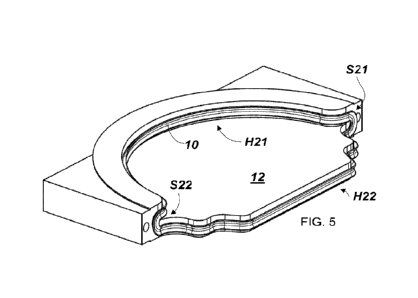
The geometry of the seal circumference is now shown in detail in Fig. 5. Here,
the
side sections S21 and S22 of the seal extend in an exemplary U-shape in planes
which are perpendicular to the closure axis A2 and parallel to the opening
axis Al,
respectively. Side sections of the sealing surface Sll and S12 extend
accordingly
(see Fig. 3). The limbs of the U-shaped sections thereby connect the two main
sections of the seal or sealing surface. Thus, the axial offset is created,
allowing the
valve to be closed by a vertical feed (along the closure axis).
The surface normals of the sealing surface 8 or the seal 10 are always at
right
angles to the opening axis Al. Therefore, at all locations of the
circumferential seal,
sealing is always perpendicular to the pressure exerted. In the direction of
contact
pressure, the seal itself is therefore never deflected or changed by the
pressure
difference - it is independent of the flooding. Retention of the closure
component 12
is uncoupled because this is taken over by the end faces of the slot 14.
In its second main section H22, the seal 10 and correspondingly the course of
the
closure component 12 are designed to seal against the track bed as sealing
surface
8. Specifically, this can mean that thus the shape of the closure component 12
and/or that of the seal 10 are adapted to a track bed. However, it can also
mean,
as in the case shown in Fig. 4, that an uneven track bed is bridged and sealed
by a
closure component 12 and seal 10 that are flat in this area by means of
resilient
CA 03193013 2023- 3- 17
8
"nestling" of the sealing material. In other words, in one embodiment, the
seal 10 is
thus configured to seal the valve opening in a gas-tight manner by elastically
deforming the seal to form a gas-tight seal in the second main section with
respect
to a track bed structure encompassed by the sealing surface. An uneven track
bed,
i.e. a track bed structure of any kind that is not a flat surface, may or may
not
include a rail as shown in Figs. 2-4. It may also be track depressions or a
combination of elevations and depressions, in which case the seal 10 per se at
least
partially compensates for such unevenness by resiliently conforming to the
shape.
Other forms of a sealing surface are of course also conceivable, for example a
straight form, so that the second main section H22 of the seal can at least
partially
dip into a flat groove in the track bed as a sealing surface (not shown). Such
grooves do not normally interfere with the vehicle 4, since magnetic guides
are
preferably used, and in particular also because the "plate", i.e. the closure
component 12 can be designed to be very thin, which means that the groove in
the
floor can be very thin. Such an additional groove would additionally lock the
closure
component in the axial direction.
The transport tube segments of a vacuum transport system can each be connected
to the housing 5, as shown in Fig. 1. A controller (not shown), in particular
a
computer, controls two adjacent ones of the vacuum valves 3a and 3b, so that
they
close or open an inner volume of the interposed transport tube segment. A
venting
device 15 is then controlled, e.g. also by the controller, to cancel a vacuum
or
negative pressure prevailing in the inner volume of the intermediate transport
tube
segment 2a by venting.
In particular, an unloading/reloading hatch, e.g. for a vehicle, is to be
provided in
some or all of the tube segments (not shown in Fig. 1).
When reference is made to "two adjacent vacuum valves", this of course also
includes the case where two segments are flooded simultaneously by closing two
valves, between which there are two tube segments and one valve remaining
open,
or even three tube segments and two valves remaining open, and so on.
It is understood that the figures shown are only schematic illustrations of
possible
exemplary embodiments. According to the invention, the various approaches can
also be combined with each other and with valves for closing process volumes
under vacuum conditions of the prior art.
CA 03193013 2023- 3- 17