Note: Descriptions are shown in the official language in which they were submitted.
CA 03193046 2023-02-24
WO 2022/046862 PCT/US2021/047490
SYSTEM AND METHOD OF CONTROLLING A MICROWAVE HEATING CYCLE
CROSS REFERENCE TO RELATED APPLICATIONS
[0001] This
application claims the benefit of U.S. Provisional Application Serial No.
63/071,475 filed August 28, 2020, the disclosure of which is expressly
incorporated
herein by reference.
BACKGROUND
[0002]
Typical microwaves do not have safety features that can facilitate use of the
microwave with an enclosed package while preventing rupture of the enclosed
package.
Such enclosed packages can unexpectedly rupture as a result of prolonged
operation of
the microwave. Accordingly, opened, vented, or otherwise unsealed food
containers or
packaging are used in typical microwaves. Therefore, typical microwaves may be
exposed to splatter of food products from the opened food containers during
use.
SUMMARY
[0003] A
first aspect of the disclosure provides a microwave appliance comprising
one or more microwave sources and a microwave chamber in electromagnetic
communication with the one or more microwave sources. The microwave appliance
comprises a product holder configured to support a food container within the
microwave
chamber and a temperature sensor configured to sense a temperature of the food
container supported within the product holder. The microwave appliance
comprises a
user interface configured to receive a temperature selection. The microwave
appliance
comprises a controller in communication with the temperature sensor and the
user
interface configured to determine a target temperature of the food container
based on the
temperature selection. The controller is configured to operate the one or more
1
CA 03193046 2023-02-24
WO 2022/046862 PCT/US2021/047490
microwave sources to heat a food product in the food container until the
temperature of
the food container is equal to the target temperature of the food container.
[0004] In some implementations of the first aspect of the disclosure, the
controller
is configured to determine the target temperature of the food container based
on a model
of experimental results that relates the temperature of the food container to
a temperature
of the food product in the food container.
[0005] In some implementations of the first aspect of the disclosure, the
food
product is sealed within the food container.
[0006] In some implementations of the first aspect of the disclosure, the
model is a
second-order polynomial equation,
= ¨ Pi
where Tc is the target temperature of the food container, Tp is the
temperature selection,
and each of X, Y, and Zare constants determined based on the experimental
results.
[0007] In some implementations of the first aspect of the disclosure, the
microwave appliance further comprises a product identification scanner in
communication
with the controller and configured read an identifier on the food container.
The controller
is configured to determine a product attribute of the food container based on
the identifier.
[0008] In some implementations of the first aspect of the disclosure, the
model
includes an attribute multiplier that scales the target temperature of the
food container
based on the product attribute.
[0009] In some implementations of the first aspect of the disclosure, the
product
attribute is selected from the group of product attributes consisting of: a
type of food
product, a type of packaging, a size of packaging, and combinations thereof.
2
CA 03193046 2023-02-24
WO 2022/046862 PCT/US2021/047490
[0010] In some implementations of the first aspect of the disclosure, the
microwave appliance further comprises a second temperature sensor configured
to sense
a temperature of the microwave chamber, wherein the model includes a cavity
temperature adjustment that is added to the target temperature of the food
container
based on the temperature of the microwave chamber.
[0011] In some implementations of the first aspect of the disclosure, the
cavity
temperature adjustment is 0 C when the temperature of the microwave chamber
is 22
C, 4 C when the temperature of the microwave chamber is 85 C, and a linear
extrapolation therebetween for other temperatures of the microwave chamber.
[0012] In some implementations of the first aspect of the disclosure, the
controller
is configured to operate the one or more microwave sources to heat the food
product in
the food container temperature to within a tolerance of the temperature
selection, wherein
the tolerance is +1- 5%.
[0013] A second aspect of the disclosure provides a method of operating a
microwave appliance. The method comprises receiving a temperature selection
from a
user interface. The method comprises determining a target temperature of a
food
container based on the temperature selection. The method comprises powering
one or
more microwave sources to heat a food product in a food container within a
microwave
chamber. The method comprises sensing a temperature of the food container with
a
temperature sensor. The method comprises turning off power to one or more
microwave
sources upon the temperature of the food container reaching the target
temperature.
[0014] In some implementations of the second aspect of the disclosure,
determining the target temperature of the food container is based on a model
of
3
CA 03193046 2023-02-24
WO 2022/046862 PCT/US2021/047490
experimental results that relates the temperature of the food container to a
temperature of
the food product in the food container.
[0015] In some implementations of the second aspect of the disclosure, the
food
product is sealed within the food container.
[0016] In some implementations of the second aspect of the disclosure, the
model
is a second-order polynomial equation,
Tv)
where Tc is the target temperature of the food container, Tp is the
temperature selection,
and each of X, Y, and Zare constants determined based on the experimental
results.
[0017] In some implementations of the second aspect of the disclosure, the
method further comprises identifying the food container based on scanning an
identifier
on the food container by a product identification scanner. The method further
comprises
determining a product attribute of the food container based on the identifier.
[0018] In some implementations of the second aspect of the disclosure, the
model
includes an attribute multiplier that scales the target temperature of the
food container
based on the product attribute.
[0019] In some implementations of the second aspect of the disclosure, the
product attribute is selected from the group of product attributes consisting
of: a type of
food product, a type of packaging, a size of packaging, and combinations
thereof.
[0020] In some implementations of the second aspect of the disclosure, the
method further comprises sensing a temperature of the microwave chamber with a
second temperature sensor. The model includes a cavity temperature adjustment
that is
added to the target temperature of the food container based on the temperature
of the
microwave chamber.
4
CA 03193046 2023-02-24
WO 2022/046862 PCT/US2021/047490
[0021] In some implementations of the second aspect of the disclosure, the
cavity
temperature adjustment is 0 C when the temperature of the microwave chamber
is 22
C, 4 C when the temperature of the microwave chamber is 85 C, and a linear
extrapolation therebetween for other temperatures of the microwave chamber.
[0022] In some implementations of the second aspect of the disclosure, the
food
product in the food container is heated to a temperature within a tolerance of
the
temperature selection, wherein the tolerance is +/- 5%.
[0023] These and other features will be more clearly understood from the
following
detailed description taken in conjunction with the accompanying drawings and
claims.
BRIEF DESCRIPTION OF THE DRAWINGS
[0024] For a more complete understanding of the present disclosure,
reference is
now made to the following brief description, taken in connection with the
accompanying
drawings and detailed description, wherein like reference numerals represent
like parts.
[0025] FIG. 1 is a front view of a microwave appliance for heating
packaged food
products to a desired temperature.
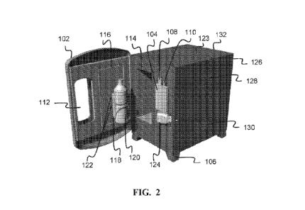
[0026] FIG. 2 is a perspective view of the microwave appliance with the
door
opened.
[0027] FIG. 3 is a left perspective view of the microwave appliance with
the
microwave access panel removed.
[0028] FIG. 4 is a right perspective view of the microwave appliance with
the
electronics access panel removed.
[0029] FIG. 5 is a block diagram of the micro-controller assembly of the
microwave
appliance.
CA 03193046 2023-02-24
WO 2022/046862 PCT/US2021/047490
[0030] FIG. 6 is a block diagram of the computer system of the microwave
appliance.
[0031] FIG. 7 is flow diagram of a control algorithm for a heating cycle
performed
by the microwave appliance.
[0032] FIGS. 8A-8E are plots of experimental data and determined trend
lines
correlating a package temperature to a product temperature for various
products.
[0033] FIG. 9 illustrates an exemplary computer system suitable for
implementing
the several embodiments of the disclosure.
DETAILED DESCRIPTION
[0034] It should be understood at the outset that although illustrative
implementations of one or more embodiments are illustrated below, the
disclosed
systems and methods may be implemented using any number of techniques, whether
currently known or in existence. The disclosure should in no way be limited to
the
illustrative implementations, drawings, and techniques illustrated below, but
may be
modified within the scope of the appended claims along with their full scope
of
equivalents. Use of the phrase "and/or" indicates that any one or any
combination of a
list of options can be used. For example, "A, B, and/or C" means "A", or "B",
or "C", or "A
and B", or "A and C", or "B and C", or "A and B and C".
[0035] A microwave appliance is disclosed herein to facilitate reliable
and efficient
heating of packaged food products. The microwave appliance includes a
temperature
sensor configured to sense a temperature of the packaged food product. In some
implementations, the temperature sensor is a contactless temperature sensor
configured
to sense a temperature of the packaged food product from outside of a
microwave
chamber. Using a contactless temperature sensor prevents interaction between
the
6
CA 03193046 2023-02-24
WO 2022/046862 PCT/US2021/047490
temperature sensor and microwave radiation used in heating the packaged food
product.
For example, the temperature sensor may be an infrared temperature sensor
arranged to
sense infrared radiation emitted by the packaged food product. In another
example, an
ultrasound sensor may be used to sense a temperature of the packaged food
product.
Other contact-based or contactless temperature sensors may be used.
[0036] As opposed to a time-based operation as with traditional microwave
appliances, operation of the disclosed microwave appliance may be based on the
measured temperature of the packaged food product determined by the
temperature
sensor. In use, a consumer may select a desired product temperature. The
desired
product temperature may be an absolute temperature input received via input on
a user
interface (e.g., 52 C) or a relative temperature input (e.g., ambient, hot,
very hot)
received via input on the user interface. The relative temperature inputs may
be
configurable by a technician to a particular set point (e.g., an ambient
selection
corresponds to 25 C, a hot selection corresponds to 55 C, etc.). The
temperature-
based operation of the microwave appliance may be used with a variety of sizes
and
types of packaged food products while ensuring that a product is not
overheated in use.
Additionally, a packaged food product may be re-heated or a partially filled
packaged
food product may be safely heated to the desired product temperature. A
maximum
operation time may also be used as a fail safe against failure of the
temperature sensor.
[0037] However, the temperature of the food container is not an accurate
measurement of a food product (e.g., beverage, soup, etc.) contained therein.
The
temperature of the food product may be higher than the temperature of the food
container, particularly for higher temperature settings for the food product.
A control
method is provided herein to calculate a target temperature of the food
container at which
7
CA 03193046 2023-02-24
WO 2022/046862 PCT/US2021/047490
a heating cycle is to be stopped. The control method stops the heating cycle
when the
measured temperature of the food container reaches the target temperature of
the food
container. The control method results in a final food product temperature
within a
tolerance (e.g., within +/- 5%) of a temperature selection received from a
consumer on
the user interface at the start of the heating cycle.
[0038] The control method uses test data of various categories and volumes
of
food products (e.g., beverages) to be heated in the microwave appliance to
determine
correlation values specific to a particular food container placed within the
microwave
appliance. The control method uses a lookup table, which has correlation
values for
different combinations of food product attributes to use to calculate the
target temperature
of the food container. In some implementations, the calculation is a second-
order
polynomial equation which correlates the measured temperature of the food
container to
a temperature of the food product contained therein, based on experimental
data. A
temperature of the microwave cavity also affects the measured temperature of
the food
container. Accordingly, the temperature of the microwave cavity may be used to
determine an adjustment to the target temperature of the food container.
[0039] An example of a microwave appliance suitable for heating a sealed
food
product container is described in WO 2020/061049, titled "Packaged Food
Product
Microwave System and Method," herein incorporated by reference in its
entirety. An
abbreviated description of the microwave appliance is provided below with
reference to
FIGS. 1-6. Other microwave appliances are contemplated by this disclosure to
be
suitable for the systems and methods described herein.
[0040] FIGS. 1-4 illustrate various views of a microwave appliance 100
suitable for
heating packaged food products to a desired temperature. FIG. 1 is a front
view of the
8
CA 03193046 2023-02-24
WO 2022/046862 PCT/US2021/047490
microwave appliance 100 showing a door 102 and a user interface 104. The door
102
includes a window 112 for accessing the user interface 104 when the door 102
is closed.
[0041] FIG. 2 is a perspective view of the microwave appliance 100 with
the door
102 opened. A door switch 532 may be positioned on a front surface of a body
123 of the
microwave appliance 100 or on the door 102 and provide a signal indicative of
a position
of the door 102 (e.g., open or closed). A holder 118 is positioned on the door
and sized
and shaped to receive a sealed food container 120, such as a food or beverage
container. In the example shown in FIG. 2, the food container 120 is a
beverage bottle.
The food container 120 may be made of plastic (e.g., polyethylene
terephthalate, high
density polyethylene, or the like), glass, ceramic, a non-foil lined carton,
or the like. The
holder 118 is positioned on the door 102 to locate the food container 120
within a
microwave cavity 114 when the door 102 is closed. For example, as the door 102
is
rotated to a closed position, the holder 118 passes through an opening in the
microwave
cavity 114 to be positioned therein.
[0042] A reactive choke 116 is positioned on the door 102 around the
holder 118
about a perimeter of the opening in the microwave cavity 114 when the door 102
is
closed. The reactive chock 116 prevents microwave radiation from passing
through the
door 102 in use. One or more product presence detectors 122 are positioned on
the door
102 about the product holder 118 and are configured to confirm whether the
food
container 120 is located within the product holder 118. The product presence
detector(s)
122 may be an optical sensor or acoustic rangefinder to detect the presence of
the food
container 120 in the product holder 118. A plurality of product presence
detectors 122
may be used to ensure detection of various sizes of food containers 120. The
plurality of
9
CA 03193046 2023-02-24
WO 2022/046862 PCT/US2021/047490
product presence detectors 122 may also be used to verify a size of the food
container
120.
[0043] The user interface 104 is positioned on a body 123 of the microwave
appliance 100. For example, the user interface 104 is positioned on the front
surface of
the body 123 of the microwave appliance 100. As shown in FIG. 2, the front
surface of
the body of the microwave appliance 100 is the same surface that includes the
opening in
the microwave cavity 114. The user interface 104 may be a touchscreen user
interface.
The user interface 104 may include a graphics port 108, such as a high-
definition
multimedia interface (HDMI) port, and a data port 110, such as a universal
serial bus
(USB) port. The graphics port 108 may supply graphics data for display on the
user
interface 104. The data port 110 may communicate touch or gesture inputs
registered on
the touchscreen. Other user interface elements may be used and communicate via
the
data port 110 or another data port. For example, in a vending environment, a
payment
module may additionally be present to facilitate receiving payment and
unlocking the door
102.
[0044] A product identification scanner 124 is positioned on the body 123
of the
microwave appliance 100. In the example shown in FIG. 2, the product
identification
scanner 124 is positioned below the user interface 104 and faces the product
holder 118
when the door 102 is open. The product identification scanner 124 may be an
optical
scanner such as a barcode reader or camera configured to read an identifier on
the food
container 120. In some implementations, more than one barcode reader may be
configured to read the identifier at multiple locations along the food
container 120.
Including multiple barcode readers facilitates identification of different
food containers 120
CA 03193046 2023-02-24
WO 2022/046862 PCT/US2021/047490
with barcodes located at different places on the container 120 and accounts
for
containers 120 of varying heights.
[0045] The product holder 118 may include an opening above a base of the
product holder 118 sized to facilitate a view of the identifier on the food
container 120
when placed in the product holder 118. For example, the identifier may be a
barcode,
symbol, quick response (OR) code, or the like that encodes a universal product
code
(UPC) or other product identifier. The product holder 118 may be sized to
allow a user to
turn the food container 120 in the product holder 118 to facilitate scanning
or otherwise
reading the identifier on the food container 120. For example, by running the
food
container 120 in the product holder 118, the identifier may be located within
the opening
of the product holder 118 and in the view of the product identification
scanner 124.
[0046] In some implementations, the product holder 118 includes a turntable
on a
base of the product holder 118 to facilitate easier turning of the food
container 120 within
the product holder 118. The turntable may be driven by a motor to
automatically scan the
identifier on the food container 120 within the product holder 118. The
turntable motor
may be activated upon the door switch providing a signal indicative of the
door 102 being
opened or after a predetermined delay of the door 102 being opened.
[0047] In some implementations, the identifier on the food container 120
may be
scanned by the product identification scanner 124 prior to insertion into the
product holder
118. In such implementations, the product presence detector(s) 122 may verify
that the
food container 120 has been inserted into the product holder 118 after being
scanned by
the product identification scanner 124.
[0048] While the product identification scanner 124 is described in an
example
above as an optical scanner, the product identification scanner 124 may be a
wireless tag
11
CA 03193046 2023-02-24
WO 2022/046862 PCT/US2021/047490
reader. For example, a wireless tag may be positioned on the food container
120, such
as on a label or closure of the food container and store the identifier for
the food container
120. The wireless tag may be a radio frequency identification (RFID) tag, a
BLUETOOTH
low energy (BLE) tag, a nearfield communication (NFC) tag, a beacon tag, or
the like.
The wireless tag reader of the product identification scanner 124 is
configured to read the
identifier for the food container 120 from the wireless tag on the food
container 120.
[0049] Based on the identifier read from the food container 120 by the
product
identification scanner 124, the microwave appliance 100 is configured to
identify a type of
food product (e.g., sugar sweetened carbonated beverage, diet carbonated
beverage,
juice beverage, tea, coffee, smoothie, dairy beverage, yogurt product, etc.),
a type of
packaging (e.g., PET carbonated beverage bottle, aluminum can, aluminum
bottle, hot-fill
PET beverage bottle, aseptic PET beverage bottle, etc.), and/or a size of
packaging (e.g.,
20 fl. oz. package, 12 fl. oz. package, 8 fl. oz. package, etc.) being
inserted into the
microwave appliance 100. Based on the identification of the type of food
product
inserted, the microwave appliance 100 may identify the dielectric constant
and/or
electrical conductivity of the food product and adjust operation of the
microwave
appliance accordingly. For example, a power level of the microwave appliance
100 may
be adjusted based on the dielectric constant and/or electrical conductivity of
the food
product. In response to reading the identifier, the microwave appliance 100
may access
a local database or a network accessible database that provides one or more
tables or
other logical structures that associate the identifier with the type of food
product, a type of
packaging, a size of packaging, a dielectric constant of the food product,
and/or an
electrical conductivity of the food product.
12
CA 03193046 2023-02-24
WO 2022/046862 PCT/US2021/047490
[0050] The body 123 of the microwave appliance 100 comprises an electronics
access panel 126 and a microwave access panel 132. The electronics access
panel 126
is positioned on a right side surface of the body 123 of the microwave
appliance 100.
The electronics access panel 126 comprises a fan vent 128 and a duct vent 130
configured to facilitate air exchange with a surrounding environment for
cooling the
microwave appliance 100. The microwave access panel 132 likewise includes a
fan vent
(not shown) and duct vent (not shown) on a left side surface of the body 123
on the
opposite side of the microwave appliance 100.
[0051] FIG. 3 is a left perspective view of the microwave appliance 100
with the
microwave access panel 132 removed. The microwave access panel 132 provides
access to a microwave compartment 133 with the microwave components of the
microwave appliance 100. FIG. 4 is a right perspective view of the microwave
appliance
100 with the electronics access panel 126 removed. The electronics access
panel 126
provides access to an electronics compartment 135. The microwave compartment
133
and the electronics compartment 135 are separated by a partition wall 134.
[0052] The microwave compartment 133 includes a microwave chamber 136
provides an enclosed volume for receiving the holder 118. The microwave
chamber 136
includes surfaces that reflect microwave radiation within the chamber 136. For
example,
the sides of the microwave chamber 136 may be made of a metal such as aluminum
or
steel. The microwave chamber 136 may include an electric field detector 538
for
measuring an electric field within the microwave chamber 136. The electric
field detector
538 may be used to estimate a volume of product within the food container 120.
[0053] The microwave chamber 136 receives microwave radiation from one or
more waveguides, such as waveguide 138 and a waveguide 144. The waveguide 144
is
13
CA 03193046 2023-02-24
WO 2022/046862 PCT/US2021/047490
shown in dashed lines in FIG. 4 to illustrate that the waveguide 144 is on the
other side of
the partition wall 134. The
waveguide 138 is offset in a vertical direction from the
waveguide 144 on the microwave chamber 136. A magnetron may be positioned
about
each of the one or more waveguides, respectively. A first magnetron (not
shown) is
positioned about the waveguide 138 for supplying microwave radiation to the
waveguide
138. The first magnetron includes an antenna located within the waveguide 138.
The
waveguide 138 is configured to direct the received microwave radiation into
the
microwave chamber 136 along a first surface of the microwave chamber 136.
Likewise, a
second magnetron (not shown) is positioned about the waveguides 144 for
supplying
microwave radiation to the waveguide 144. The second magnetron includes an
antenna
located within the waveguide 144. The waveguide 144 is configured to direct
the
received microwave radiation into a second surface the microwave chamber 136
along a
second surface of the microwave chamber 136.
[0054] While
two magnetrons are disclosed, more or fewer magnetrons may be
used. An additional waveguide may be provided for each such additional
magnetron.
Providing additional magnetrons enables the creation of more complex patterns
of
standing waves for ensuring strong coupling to the food product in a larger
variety of food
containers 120.
[0055] In
some implementations, depending on the product identified by the
product identification scanner 124 a power level of one or more of the
magnetrons may
be adjusted or turned off during use. For example, because the waveguide 138
introduces microwave radiation into the microwave chamber 136 at a location
higher from
the waveguide 144, if a short bottle or other food container 120 is placed in
the product
holder 118, then the first magnetron may be reduced or turned off during use.
14
CA 03193046 2023-02-24
WO 2022/046862 PCT/US2021/047490
[0056] While the example shown in FIG. 3 provides waveguides 138, 144 for
supplying microwave radiation to the microwave chamber 136 from opposite sides
of the
microwave chamber 136, other configurations may be used. In some
implementations, a
solid state microwave source may be used instead of one or more of the
magnetrons.
[0057] The microwave compartment 133 also includes a first magnetron power
supply 154 and a second magnetron power supply 156 for powering the magnetrons
positioned about the waveguides 138, 144. The magnetron power supplies 154,
156
may be a half-wave voltage doubler power supply or an inverter or switch mode
power
supply. Other power supply types may also be used.
[0058] A temperature sensor 162 is positioned about the bottom surface of
the
microwave chamber 136 and configured to measure a temperature of the food
container
120 in the product holder 118 when the door 102 is closed. In various
implementations,
the temperature sensor 162 may be positioned in other locations to sense a
temperature
of the food container 120. The temperature sensor 162 may be a contactless
temperature sensor configured to sense a temperature of the packaged food
product
from outside of a microwave chamber. Using a contactless temperature sensor
prevents
interaction between the temperature sensor and microwave radiation used in
heating the
food product in the food container 120. For example, the temperature sensor
162 may be
an infrared temperature sensor arranged to sense infrared radiation emitted by
the food
product in the food container 120. In another example, an ultrasound sensor
may be
used to sense a temperature of the packaged food product. Other contact-based
or
contactless temperature sensors may be used. In some implementations, an
additional
temperature sensor (not shown) may be positioned to measure a temperature
within the
microwave cavity 114.
CA 03193046 2023-02-24
WO 2022/046862 PCT/US2021/047490
[0059] The
food container 120 may have a variety of shapes and sizes and have
product labels at different locations. The product label may insulate or
otherwise impact a
temperature reading for the food container 120 by the temperature sensor 162.
However,
the base of food containers 120 typically have less variety or variability,
particularly at a
central location of the base of the food container 120. For example, beverage
containers
typically have a flat or petaloid shaped base. Even with a petaloid shaped
base, a central
location of the base of the beverage container is largely uniform.
Additionally, product
labels are rarely located on the base of the food container 120.
[0060] The
temperature sensor 162 is arranged to face towards a bottom of the
product holder 118 when the door 102 is closed. The bottom of the product
holder 118
may include a hole or aperture through which the temperature sensor 162 may
view the
base of the food container 120. Measuring the temperature from the bottom of
the food
container 120 allows for accurately sensing a temperature of a greater variety
of package
types by not needing to take into account different package sizes, shapes, and
product
label positions. The temperature may be measured from other locations on the
food
container 120, such as along a sidewall, closure, or other location on the
food container.
[0061] As
best seen in FIG. 4, the electronics compartment 135 includes a
computer system 600 and a micro-controller assembly 500. A port access door
170 is
located on the rear surface of the body 123 of the microwave appliance 100
provides
access to one or more input/output (I/O) ports on the computer system 600. The
partition
wall 134 isolates the components in the electronics compartment 135 from heat
and
electromagnetic noise generated form components in the microwave compartment
133.
[0062] FIG.
5 is a block diagram of the micro-controller assembly 500 of the
microwave appliance 100. The micro-controller assembly 500 includes a micro-
controller
16
CA 03193046 2023-02-24
WO 2022/046862 PCT/US2021/047490
502 and an I/O interface board 504. The I/O interface board 504 is configured
to receive
and communicate various input signals to the micro-controller 502. The micro-
controller
502 includes firmware 506 for processing the received input signals and
generating
output control signals 508. The I/O interface board 504 supplies the output
control
signals 508 to control components of the microwave compartment 133.
[0063] The I/O interface board 504 also receives analog inputs from the
temperature sensor 162 and an electric field detector 538. As noted above, the
electric
field detector 538 may be used to estimate a volume of product within the food
container
120. Additionally, the electric field detector 538 may be used to verify that
electric fields
within the microwave chamber 136 are in an expected range of normal operation.
For
example, if a metallic food container 120, such as a 12 oz. aluminum can, were
inserted
into the microwave appliance 100, the electric field detector 538 would sense
a lower
than expected or zero value load. At the same time, the product presence
detector(s)
122 would sense that the food container 120 is present in the product holder
118.
Similarly, if no product were inserted into the microwave appliance 100, the
electric field
detector 538 would sense a lower than expected or zero value load. The product
presence detector(s) 122 would also sense that no product is present in the
product
holder 118. In either case, operation of the microwave appliance 100 may be
prevented
from being started or otherwise terminated upon the electric field detector
538 sensing a
load value below an allowable minimum as indicated by a maximum allowable
electric
field threshold value.
[0064] The maximum electric field threshold value may correspond to a
minimum
amount of volume of a given type of food product in a given food container
120. For
example, the maximum threshold value may be an expected electric field reading
that
17
CA 03193046 2023-02-24
WO 2022/046862 PCT/US2021/047490
corresponds to at least 5%, 10%, or 25% of a volume of a given food container
120 for
the type of food product contained in the given food container 120.
[0065] Different materials have different dielectric constants and
electrical
conductivity thus couple to, absorb, or otherwise react to microwave radiation
differently.
For example, the dielectric constant of PET is about 1-3 C whereas water has a
dielectric
constant of about 80 C. Likewise, the electrical conductivity of PET is about
10-21 S/m,
whereas saline water solutions have an electrical conductivity of around 1-5
S/m.
Therefore, food products much more readily absorb microwave radiation than the
containers in which they are typically contained.
[0066] However, different food products have different electrical
properties. Based
upon the electrical properties (e.g., dielectric constant and/or electrical
conductivity) of the
food product being inserted into the microwave chamber 136, such as based on a
reading from the product identification scanner 124, and a detected electric
field strength
measured by the electric field detector 538, a volume of the food product may
be
estimated. Using the estimated volume of food product inserted into the
microwave
chamber 136, operation of the first magnetron power supply 154 and/or the
second
magnetron power supply 156 may be modified. For example, a power level of one
or
more of the magnetron power supplies 154, 156 may be adjusted based on the
estimated
volume to avoid flash boiling or otherwise reduce a risk of pressure buildup
in the food
container 120. Therefore, even partially full food containers 120 may be
safely heated to
a target temperature in the microwave appliance 100.
[0067] The I/O interface board 556 also includes an output block 556 for
supplying
output control signals 508 to components in the microwave compartment 133. A
first
magnetron signal 554 is provided to the first magnetron MOSFET to turn on or
off the first
18
CA 03193046 2023-02-24
WO 2022/046862 PCT/US2021/047490
power relay. Likewise, a second magnetron signal 556 is provided to the second
magnetron MOSFET to turn on or off the second power relay. Upon the first
power relay
being turned on, power is provided to the first magnetron power supply 154 and
a
corresponding fan. Upon the second power relay being turned on, power is
provided to
the second magnetron power supply 156 and a corresponding fan.
[0068] A first power control signal 558 is provided to the first magnetron
power
supply 154 to modulate the power output by the first magnetron power supply
154 to the
first magnetron. A second power control signal 560 is provided to the second
magnetron
power supply 156 to modulate the power output by the second magnetron power
supply
156 to the second magnetron. In some implementations, the first and second
power
control signals 558, 560 are pulse width modulated control signals. The first
and second
power control signals 558, 560 may be the same or different. For example, the
first and
second magnetron power supplies 154, 156 may be operated to provide different
power
levels to their respective magnetrons.
[0069] FIG. 6 is a block diagram of the computer system 600 of the
microwave
appliance 100. The computer system 600 includes an operating system 602 and
one or
more applications 604 installed on the operating system 602. The computer 600
also
includes a memory 606 with a file system for storing images, audio, and video
data 608
for display on the user interface 104 or output from the speaker 168. The one
or more
applications 604 control operation of components on a communications bus 610,
such as
the micro-controller 502. An I/O interface 612 provides communication between
the one
or more applications 604 and the user interface 104, for example supplying
video or
image data and receiving touch inputs from a touchscreen. A port 614, which
may be
accessible via the port access door 170, provides access to technicians to
download
19
CA 03193046 2023-02-24
WO 2022/046862 PCT/US2021/047490
usage and diagnostic data as well as to upload software updates for the
application(s)
604 or the firmware 506. A database 616 may locally store the usage and
diagnostic
data for the microwave appliance 100. For example, the usage data may include
how
many times the door 102 is opened, which products are scanned by the product
identification scanner 124, what temperature is selected on the user interface
104 to heat
the products, and when each of these events occur. Other usage data may be
collected.
Diagnostic data may include logs of the inputs received on the input block
516, the
analog input 544, and the analog amplifier 542 as well as the control signals
508. Other
diagnostic data may be stored in the database 616. A modem 618 may also be
included
for uploading the usage and diagnostic data to a remote server (not shown) or
for
receiving software updates from the remote server. Other
configurations and
components are contemplated by this disclosure.
[0070]
Operation of the microwave appliance 100 is based on the measured
temperature of the food container 120 as determined by the temperature sensor
162.
However, the temperature of the food container 120 is not an accurate
measurement of a
food product (e.g., beverage, soup, etc.) contained therein. The temperature
of the food
product may be higher than the temperature of the food container 120,
particularly for
higher temperature settings for the food product.
[0071] A
control method is provided herein to calculate a target temperature of the
food container 120 at which a heating cycle is to be stopped (e.g., turning
off power to the
magnetron(s)). The control method stops the heating cycle when the measured
temperature of the food container 120 reaches the target temperature of the
food
container 120. The control method results in a final food product temperature
within a
CA 03193046 2023-02-24
WO 2022/046862 PCT/US2021/047490
tolerance (e.g., within +/- 5%) of a temperature selection received from a
consumer on
the user interface 104 at the start of the heating cycle.
[0072] Test
data of various categories and volumes of food products (e.g.,
beverages) to be heated in the microwave appliance 100 (e.g., water, tea,
juice, coffee
without cream/sugar, coffee with cream/sugar, etc.) is used to determine
correlation
values specific to a particular food container 120 placed within the microwave
appliance
100. The control method uses a lookup table, which has correlation values for
different
combinations of food product attributes to use to calculate the target
temperature of the
food container 120. In some implementations, the calculation is a second-order
polynomial equation which correlates the measured temperature of the food
container
120 to a temperature of the food product contained therein, based on
experimental data.
A temperature of the microwave cavity 114 also affects the measured
temperature of the
food container 120. Accordingly, the temperature of the microwave cavity 114
may be
used to determine an adjustment to the target temperature of the food
container 120.
[0073] FIG.
7 is flow diagram of a control method 700 for a heating cycle
performed by the microwave appliance 100. In various implementations, the
control
method 700 is executed by the micro-controller assembly 500 (e.g., micro-
controller 502)
and/or the computer system 600.
[0074] At
702, the control method 700 identifies the food container 120 inserted
into the microwave appliance 100. For example, the product identification
scanner 124
scans an identifier on the food container 120, as described above. Based
on the
identifier read from the food container 120 by the product identification
scanner 124, the
microwave appliance 100 is configured to identify a type or category of food
product, a
type of packaging, and/or a size or volume of packaging.
21
CA 03193046 2023-02-24
WO 2022/046862 PCT/US2021/047490
[0075] At 704, the control method 700 receives a user input via the user
interface
104 of a product temperature for a food product within the food container 120
to be
heated. The input product temperature may be an absolute temperature input
received
via input on the user interface 104 (e.g., 52 C) or a relative temperature
input (e.g.,
ambient, hot, very hot) received via input on the user interface 104. Relative
temperature
inputs may be configured within the microwave appliance 100 to correspond to
particular
absolute temperatures (e.g., a hot selection corresponds to 55 C, etc.).
[0076] At 706, the control method 700 determines a target temperature of
the food
container 120 that correlates with the input product temperature received via
the user
interface 104. The correlation between the temperature of the food container
120 and the
temperature of the food product within the food container 120 is determined
experimentally. While an example is provided herein of a second-order
polynomial
equation which models the relationship between the temperature of the food
container
120 and the temperature of the food product within the food container 120,
other
statistical or machine learning methods may be used to model the values
determined in
the experimental results.
[0077] FIGS. 8A-8E are plots of experimental data and determined trend
lines
correlating a package temperature to a product temperature for various
products. As
shown, a non-linear relationship exist between the package temperature and the
product
temperature. Specifically, small changes in the package temperature (IR Temp)
were
found to result in large changes in the product temperature (TO Temp). Such
non-linear
effects were determined to be based in part on the increased pressure within
the sealed
food container 120 as it is heated. For example, the pressure within the food
container
120 may increase to 8-22 psi in a heating cycle, more typically around 14 psi.
The
22
CA 03193046 2023-02-24
WO 2022/046862 PCT/US2021/047490
increasing pressure leads to non-linearity of the specific heat of water.
Additionally, the
insulating properties of the food container 120 dampen and delay the heat
transfer from
the food product to the food container 120.
[0078] Based on the experimental results, a second-order polynomial
equation
was determined to model the relationship between the temperature of the food
container
120 and the temperature of the food product within a tolerance (e.g., within
+/- 5%) of a
temperature selection received from a consumer on the user interface 104. The
second-
order polynomial equation is,
= (µg Tp2 ¨ (Y Tp ) Equation (1)
where Tc is the target temperature of the food container 120, Tp is the target
temperature
of the food product (e.g., the temperature selection received via the user
interface 104),
and each of X, Y, and Zare constants determined based on the experimental
results.
[0079] In some examples, each of the constants X and Y are in turn
determined
from a second order polynomial that characterizes one or more physical
attributes of the
identified food container 120 (e.g., identified type or category of food
product, type of
packaging, size or volume of packaging, estimated volume of product based on
electric
field detector 538, etc.). In a specific example where the estimated volume of
product
detected within the food container 120 is a primary contributing factor,
X= 6.67e-8x2¨ 2.96e-5x + 0.0109, Equation (2)
Y= 5e-6x2 ¨ 0.00265x+ 0.8117, Equation (3)
Z = 29.6928, Equation (4)
where x is the estimated volume of produce detected by the electric field
detector 538. In
some implementations x is a value combining one or more of the physical
attributes of the
identified food container 120.
23
CA 03193046 2023-02-24
WO 2022/046862 PCT/US2021/047490
[0080] In some embodiments, the microwave appliance 100 may maintain a
model
for each product anticipated to be heated within the microwave appliance 100.
However,
such an approach requires extensive testing of each combination of product,
packaging
type, and package volume. Rather than individually testing each combination,
the
microwave appliance 100 may maintain one or more attribute multipliers that
model the
impact of each attribute variation on the determination of the target
temperature of the
product container 120. In some implementations, a single attribute multiplier
may be
used. In some implementations, more than one attribute multiplier may be used.
Each of
the one or more attribute multipliers is multiplied by the value of Equation
(1) as,
T, = ((X $. T;) ¨(Y = Tv) 4- n Z)
i Equation (5)
,
where am is the attribute multiplier(s) and n is the number of attribute
multipliers.
Therefore, the attribute multiplier(s) scale the target temperature of the
product container
120 based on the attribute(s) of the product container determined based on the
identifier
read from the food container 120 by the product identification scanner 124.
[0081] For example, for beverage food products, a category multiplier may
include
a coffee multiplier of 1.2, a tea multiplier of 1.1, a juice multiplier of
1.07, a water multiplier
of 1.25, an animal milk multiplier of 1.4, and a plant dairy multiplier of
1.3. Likewise, a
package volume multiplier may include a 1.15 multiplier for beverage
containers between
100-225 mL, a 1.25 multiplier for beverage containers between 226-350 mL, a
1.35
multiplier for beverage containers between 351-475 mL, and a 1.4 multiplier
for beverage
containers between 476-600 mL. Other attribute multipliers and values for
those
multipliers are contemplated by this disclosure.
24
CA 03193046 2023-02-24
WO 2022/046862 PCT/US2021/047490
[0082] Returning to FIG. 7, at 708, the control method 700 optionally
measures a
temperature of the microwave cavity 114. A temperature of the microwave cavity
114
also affects the measured temperature of the food container 120. Accordingly,
the
temperature of the microwave cavity 114 may be used to determine an adjustment
to the
target temperature of the food container 120. As the temperature within the
microwave
cavity 114 increases, the temperature of the food container 120 likewise
increases based
on the heat present within the microwave cavity 114. Accordingly, the target
temperature
of the food container 120 is reached sooner than with a lower temperature in
the
microwave cavity 114. Therefore, a cavity temperature adjustment may be added
to
Equation (1) or Equation (5), respectively, as,
) - (Y T p) Z) CT
Equation (6)
= ((X (Y *Tp)+ Z) f] + CT
Equation (7)
where CT is the cavity temperature adjustment. In an example, the cavity
temperature
adjustment, CT, is 0 C when the temperature of the microwave cavity 114 is 22
C, 4 C
when the temperature of the microwave cavity 114 is 85 C, and a linear
extrapolation
therebetween for other temperatures of the microwave cavity 114.
[0083] At 710, the control method 700 starts the heating cycle by turning
on power
to the magnetron(s). At 714, the control method 700 receives a measurement of
a
temperature of the food container 120 using the temperature sensor 162. At
716, the
control method 700 determines whether the measured temperature of the food
container
120 is equal to the target temperature of the food container 120. If not, the
control
method 700 continues the heating cycle and proceeds back to 712. Otherwise, if
the
measured temperature of the food container 120 is equal to the determined
target
CA 03193046 2023-02-24
WO 2022/046862 PCT/US2021/047490
temperature of the food container, the control method stops the heating cycle
(e.g., turns
off power to the magnetron(s)), at 716. Accordingly, the product within the
food container
120 is heated to the input product temperature received at the user interface
104 to within
a tolerance (e.g., within +/- 5%).
[0084] It
should be appreciated that the logical operations described herein with
respect to the various figures may be implemented (1) as a sequence of
computer
implemented acts or program modules (i.e., software) running on a computing
device
(e.g., the computing device described in FIG. 9), (2) as interconnected
machine logic
circuits or circuit modules (i.e., hardware) within the computing device
and/or (3) a
combination of software and hardware of the computing device. Thus, the
logical
operations discussed herein are not limited to any specific combination of
hardware and
software. The implementation is a matter of choice dependent on the
performance and
other requirements of the computing device.
Accordingly, the logical operations
described herein are referred to variously as operations, structural devices,
acts, or
modules. These operations, structural devices, acts and modules may be
implemented
in software, in firmware, in special purpose digital logic, and any
combination thereof. It
should also be appreciated that more or fewer operations may be performed than
shown
in the figures and described herein. These operations may also be performed in
a
different order than those described herein.
[0085]
Referring to FIG. 9, an example computing device 1100 upon which
embodiments of the invention may be implemented is illustrated. For example,
the
microwave appliance 100, user interface 104, micro-controller 502, and/or
computer 600
described herein may each be implemented as a computing device, such as
computing
device 1100. It should be understood that the example computing device 1100 is
only
26
CA 03193046 2023-02-24
WO 2022/046862 PCT/US2021/047490
one example of a suitable computing environment upon which embodiments of the
invention may be implemented. Optionally, the computing device 1100 can be a
well-
known computing system including, but not limited to, personal computers,
servers,
handheld or laptop devices, multiprocessor systems, microprocessor-based
systems,
network personal computers (PCs), minicomputers, mainframe computers, embedded
systems, and/or distributed computing environments including a plurality of
any of the
above systems or devices.
Distributed computing environments enable remote
computing devices, which are connected to a communication network or other
data
transmission medium, to perform various tasks. In
the distributed computing
environment, the program modules, applications, and other data may be stored
on local
and/or remote computer storage media.
[0086] In an
embodiment, the computing device 1100 may comprise two or more
computers in communication with each other that collaborate to perform a task.
For
example, but not by way of limitation, an application may be partitioned in
such a way as
to permit concurrent and/or parallel processing of the instructions of the
application.
Alternatively, the data processed by the application may be partitioned in
such a way as
to permit concurrent and/or parallel processing of different portions of a
data set by the
two or more computers. In an embodiment, virtualization software may be
employed by
the computing device 1100 to provide the functionality of a number of servers
that is not
directly bound to the number of computers in the computing device 1100. For
example,
virtualization software may provide twenty virtual servers on four physical
computers. In
an embodiment, the functionality disclosed above may be provided by executing
the
application and/or applications in a cloud computing environment. Cloud
computing may
comprise providing computing services via a network connection using
dynamically
27
CA 03193046 2023-02-24
WO 2022/046862 PCT/US2021/047490
scalable computing resources. Cloud computing may be supported, at least in
part, by
virtualization software. A cloud computing environment may be established by
an
enterprise and/or may be hired on an as-needed basis from a third party
provider. Some
cloud computing environments may comprise cloud computing resources owned and
operated by the enterprise as well as cloud computing resources hired and/or
leased
from a third party provider.
[0087] In its most basic configuration, computing device 1100 typically
includes at
least one processing unit 1120 and system memory 1130. Depending on the exact
configuration and type of computing device, system memory 1130 may be volatile
(such
as random access memory (RAM)), non-volatile (such as read-only memory (ROM),
flash
memory, etc.), or some combination of the two. This most basic configuration
is
illustrated in FIG. 9 by dashed line 1110. The processing unit 1120 may be a
standard
programmable processor that performs arithmetic and logic operations necessary
for
operation of the computing device 1100. While only one processing unit 1120 is
shown,
multiple processors may be present. Thus, while instructions may be discussed
as
executed by a processor, the instructions may be executed simultaneously,
serially, or
otherwise executed by one or multiple processors. The computing device 1100
may also
include a bus or other communication mechanism for communicating information
among
various components of the computing device 1100.
[0088] Computing device 1100 may have additional features/functionality.
For
example, computing device 1100 may include additional storage such as
removable
storage 1140 and non-removable storage 1150 including, but not limited to,
magnetic or
optical disks or tapes. Computing device 1100 may also contain network
connection(s)
1180 that allow the device to communicate with other devices such as over the
28
CA 03193046 2023-02-24
WO 2022/046862 PCT/US2021/047490
communication pathways described herein. The network connection(s) 1180 may
take
the form of modems, modem banks, Ethernet cards, universal serial bus (USB)
interface
cards, serial interfaces, token ring cards, fiber distributed data interface
(FDDI) cards,
wireless local area network (WLAN) cards, radio transceiver cards such as code
division
multiple access (CDMA), global system for mobile communications (GSM), long-
term
evolution (LTE), worldwide interoperability for microwave access (WiMAX),
and/or other
air interface protocol radio transceiver cards, and other well-known network
devices.
Computing device 1100 may also have input device(s) 1170 such as a keyboards,
keypads, switches, dials, mice, track balls, touch screens, voice recognizers,
card
readers, paper tape readers, or other well-known input devices. Output
device(s) 1160
such as a printers, video monitors, liquid crystal displays (LCDs), touch
screen displays,
displays, speakers, etc. may also be included. The additional devices may be
connected
to the bus in order to facilitate communication of data among the components
of the
computing device 1100. All these devices are well known in the art and need
not be
discussed at length here.
[0089] The processing unit 1120 may be configured to execute program code
encoded in tangible, computer-readable media. Tangible, computer-readable
media
refers to any media that is capable of providing data that causes the
computing device
1100 (i.e., a machine) to operate in a particular fashion. Various computer-
readable
media may be utilized to provide instructions to the processing unit 1120 for
execution.
Example tangible, computer-readable media may include, but is not limited to,
volatile
media, non-volatile media, removable media and non-removable media implemented
in
any method or technology for storage of information such as computer readable
instructions, data structures, program modules or other data. System memory
1130,
29
CA 03193046 2023-02-24
WO 2022/046862 PCT/US2021/047490
removable storage 1140, and non-removable storage 1150 are all examples of
tangible,
computer storage media. Example tangible, computer-readable recording media
include,
but are not limited to, an integrated circuit (e.g., field-programmable gate
array or
application-specific IC), a hard disk, an optical disk, a magneto-optical
disk, a floppy disk,
a magnetic tape, a holographic storage medium, a solid-state device, RAM, ROM,
electrically erasable program read-only memory (EEPROM), flash memory or other
memory technology, CD-ROM, digital versatile disks (DVD) or other optical
storage,
magnetic cassettes, magnetic tape, magnetic disk storage or other magnetic
storage
devices.
[0090] It is fundamental to the electrical engineering and software
engineering arts
that functionality that can be implemented by loading executable software into
a computer
can be converted to a hardware implementation by well-known design rules.
Decisions
between implementing a concept in software versus hardware typically hinge on
considerations of stability of the design and numbers of units to be produced
rather than
any issues involved in translating from the software domain to the hardware
domain.
Generally, a design that is still subject to frequent change may be preferred
to be
implemented in software, because re-spinning a hardware implementation is more
expensive than re-spinning a software design. Generally, a design that is
stable that will
be produced in large volume may be preferred to be implemented in hardware,
for
example in an application specific integrated circuit (ASIC), because for
large production
runs the hardware implementation may be less expensive than the software
implementation. Often a design may be developed and tested in a software form
and
later transformed, by well-known design rules, to an equivalent hardware
implementation
in an application specific integrated circuit that hardwires the instructions
of the software.
CA 03193046 2023-02-24
WO 2022/046862 PCT/US2021/047490
In the same manner as a machine controlled by a new ASIC is a particular
machine or
apparatus, likewise a computer that has been programmed and/or loaded with
executable
instructions may be viewed as a particular machine or apparatus.
[0091] In an example implementation, the processing unit 1120 may execute
program code stored in the system memory 1130. For example, the bus may carry
data
to the system memory 1130, from which the processing unit 1120 receives and
executes
instructions. The data received by the system memory 1130 may optionally be
stored on
the removable storage 1140 or the non-removable storage 1150 before or after
execution
by the processing unit 1120.
[0092] It should be understood that the various techniques described
herein may
be implemented in connection with hardware or software or, where appropriate,
with a
combination thereof. Thus, the methods and apparatuses of the presently
disclosed
subject matter, or certain aspects or portions thereof, may take the form of
program code
(i.e., instructions) embodied in tangible media, such as floppy diskettes, CD-
ROMs, hard
drives, or any other machine-readable storage medium wherein, when the program
code
is loaded into and executed by a machine, such as a computing device, the
machine
becomes an apparatus for practicing the presently disclosed subject matter. In
the case
of program code execution on programmable computers, the computing device
generally
includes a processor, a storage medium readable by the processor (including
volatile and
non-volatile memory and/or storage elements), at least one input device, and
at least one
output device. One or more programs may implement or utilize the processes
described
in connection with the presently disclosed subject matter, e.g., through the
use of an
application programming interface (API), reusable controls, or the like. Such
programs
may be implemented in a high level procedural or object-oriented programming
language
31
CA 03193046 2023-02-24
WO 2022/046862 PCT/US2021/047490
to communicate with a computer system. However, the program(s) can be
implemented
in assembly or machine language, if desired. In any case, the language may be
a
compiled or interpreted language and it may be combined with hardware
implementations.
[0093] Embodiments of the methods and systems may be described herein with
reference to block diagrams and flowchart illustrations of methods, systems,
apparatuses
and computer program products. It will be understood that each block of the
block
diagrams and flowchart illustrations, and combinations of blocks in the block
diagrams
and flowchart illustrations, respectively, can be implemented by computer
program
instructions. These computer program instructions may be loaded onto a general
purpose
computer, special purpose computer, or other programmable data processing
apparatus
to produce a machine, such that the instructions which execute on the computer
or other
programmable data processing apparatus create a means for implementing the
functions
specified in the flowchart block or blocks.
[0094] These computer program instructions may also be stored in a
computer-
readable memory that can direct a computer or other programmable data
processing
apparatus to function in a particular manner, such that the instructions
stored in the
computer-readable memory produce an article of manufacture including computer-
readable instructions for implementing the function specified in the flowchart
block or
blocks. The computer program instructions may also be loaded onto a computer
or other
programmable data processing apparatus to cause a series of operational steps
to be
performed on the computer or other programmable apparatus to produce a
computer-
implemented process such that the instructions that execute on the computer or
other
32
CA 03193046 2023-02-24
WO 2022/046862 PCT/US2021/047490
programmable apparatus provide steps for implementing the functions specified
in the
flowchart block or blocks.
[0095] Accordingly, blocks of the block diagrams and flowchart
illustrations support
combinations of means for performing the specified functions, combinations of
steps for
performing the specified functions and program instruction means for
performing the
specified functions. It will also be understood that each block of the block
diagrams and
flowchart illustrations, and combinations of blocks in the block diagrams and
flowchart
illustrations, can be implemented by special purpose hardware-based computer
systems
that perform the specified functions or steps, or combinations of special
purpose
hardware and computer instructions.
[0096] While several embodiments have been provided in the present
disclosure, it
should be understood that the disclosed systems and methods may be embodied in
many other specific forms without departing from the spirit or scope of the
present
disclosure. The present examples are to be considered as illustrative and not
restrictive,
and the intention is not to be limited to the details given herein. For
example, the various
elements or components may be combined or integrated in another system or
certain
features may be omitted or not implemented.
[0097] Also, techniques, systems, subsystems, and methods described and
illustrated in the various embodiments as discrete or separate may be combined
or
integrated with other systems, modules, techniques, or methods without
departing from
the scope of the present disclosure. Other items shown or discussed as
directly coupled
or communicating with each other may be indirectly coupled or communicating
through
some interface, device, or intermediate component, whether electrically,
mechanically, or
otherwise. Other examples of changes, substitutions, and alterations are
ascertainable
33
CA 03193046 2023-02-24
WO 2022/046862 PCT/US2021/047490
by one skilled in the art and could be made without departing from the spirit
and scope
disclosed herein.
34