Note: Descriptions are shown in the official language in which they were submitted.
METHOD FOR LEAK TESTING A SEALED AND
THERMALLY INSULATING TANK FOR STORING A FLUID
[0001] [The invention relates to the field of sealed and thermally insulating
tanks with
membranes. In particular, the invention relates to the field of sealed and
thermally
insulating tanks for the storage and/or the transport of liquid at low
temperature, such as
tanks for transporting liquefied petroleum gas (also referred to as LPG)
having, for example,
a temperature between -50 C and 0 C, or for transporting liquefied natural gas
(LNG) at
approximately -162 C at atmospheric pressure. These tanks may be installed
onshore or
on a floating structure. In the case of a floating structure, the tank may be
intended for the
transport of liquefied gas at low temperature or to receive liquefied gas at
low temperature
which is used as fuel for propelling the floating structure. More
specifically, the invention
relates to devices and methods for detecting leakages in a secondary membrane
of such
a tank.
[0002] Tanks of vessels for transporting liquefied natural gas generally
comprise a carrier
structure which provides mechanical rigidity, a primary sealing membrane which
is
intended to be in contact with the product contained in the tank and a
secondary sealing
membrane which is arranged between the primary sealing membrane and the
carrier
structure. The secondary sealing membrane is intended to retain the product in
the event
of a leakage in the primary sealing membrane. The space between the primary
sealing
membrane and the secondary membrane is referred to as the primary space and
the space
between the secondary sealing membrane and the carrier structure is referred
to as the
secondary space.
[0003] The secondary sealing membrane is invisible and inaccessible after the
tank has been
produced. It is thus impossible to directly observe any faults of this
membrane such as a
scratch, a local dislocation of the membrane or an air channel between two
components
of which the membrane is composed.
[0004] In order to diagnose the sealing of the secondary membrane, a known
reference is, in
particular, document W02020128370, filed in the name of the applicant, which
describes
a method for checking the sealing of this secondary membrane. In that method,
the
presence of leaks at the secondary sealing membrane is detected in particular
by applying
to the primary insulation space an inert pressure that is higher in comparison
with that of
the secondary insulating space.
CA 03193539 2023- 3- 22
2
[0005] The inert gas used in such a method is conventionally nitrous oxide.
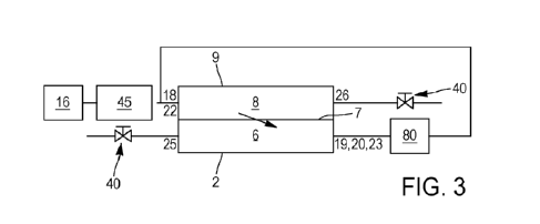
However, this gas
is stored on board the ship in limited quantity and has numerous applications
on the ship,
whenever inert gas needs to be circulated.
[0006] Now, the applicant has found that, in instances in which leaks in the
secondary sealing
membrane are substantial, the amount of inert gas needed for the leak
detection operation
is very great, to the point of completely exhausting the ship's supply of
inert gas during the
operation of checking the sealing of the tank. This is because the inert gas,
once it has
been used for each checking operation, is released into the surrounding air.
[0007] At the present time, there is no method for testing the sealing of the
secondary sealing
membrane in which the quantity of inert gas used is reduced, or even in which
the sealing
is checked with a neutral balance sheet regarding the inert gas.
[0008] A notion on which the invention is based is to provide devices and
methods for
detecting leakages in a sealed and thermally insulating tank which is filled
with liquid at
low temperature which does not have these disadvantages. In this manner, an
object of
the invention is to be able to locate abnormal porosities of the secondary
sealing
membrane, even when the leakage rate is very high.
[0009] The present invention thus relates to a method for checking the sealing
of a sealed
and thermally insulating tank for storing a liquefied gas at low temperature,
the tank being
at a low temperature, the tank comprising a carrier structure which has an
inner hull and
an outer hull, a confined space between the inner hull and the outer hull, a
primary sealing
membrane which is intended to be in contact with the liquefied gas at low
temperature
contained in the tank, and a secondary sealing membrane which is arranged
between the
primary sealing membrane and the inner hull, a primary space between the
primary sealing
membrane and the secondary sealing membrane and a secondary space between the
secondary sealing membrane and the inner hull, the primary space and the
secondary
space comprising insulating materials, the primary space comprising at least
one primary
gas inlet and the secondary space comprising at least one secondary gas
outlet, said
primary sealing membrane resting directly on the insulating materials
contained in the
primary space and said secondary sealing membrane resting directly on the
insulating
materials contained in the secondary space, the method comprising the
following
successive steps for detecting the location of a sealing defect of the
secondary sealing
membrane in the form of a cold spot on the outer surface of the inner hull:
- a step referred to as the main step in which the secondary space is brought
to a
pressure lower than the pressure of the primary space, with a pressure
differential P1,
by injecting an inert gas into the primary space via the primary gas inlet and
causing
CA 03193539 2023- 3- 22
3
gas to be expelled or drawn from the secondary gas outlet of the secondary
space and
then by measuring the temperature of an outer surface of the inner hull from
the
confined space situated around the inner hull;
-
a step referred to as a subsequent step in which the temperature of the
outer surface
of the inner hull is measured from the confined space under the normal
operating
conditions of the tank.
[0010] The invention is characterized in that at least some of the inert gas
injected into the
primary space is recovered by at least one secondary outlet of the secondary
space to be
reinjected into the primary space.
[0011] Thus, the applicant is proposing a simple, effective and inexpensive
system for
performing a leak test on the secondary membrane of a tank for a liquefied
gas, without
the loss of inert gas or while losing a reduced quantity thereof, such that
the checking
method can always be performed, whatever the conditions of sealing of the
secondary
sealing membrane.
[0012] Specifically, after several trials, the applicant has sought out an
architecture that is at
once simple, robust and efficient, for recirculating the inert gas used during
implementation
of the method according to the invention.
[0013] The term "liquefied gas at low temperature" is intended to be
understood to be any
body which is in the vapor state under normal pressure and temperature
conditions and
which has been placed in the liquid state by lowering the temperature thereof.
[0014] The term "confined space" is intended to be understood to be the
ballasts, the duct
keels, the cofferdams, the passageways and the closure bridge of the tank,
also referred
to as the "trunk deck".
[0015] The expression "tank at low temperature" is intended to be understood
to be a tank in
which the liquefied gas at low temperature occupies at least 20% of the volume
of the tank,
preferably 70%, or a tank which does not contain a load of liquefied gas, or a
volume less
than 20% of the volume of the tank but then, in this instance, the tank is
cooled by means
of spraying, or projection, of a liquefied gas at low temperature, such as,
for example, liquid
nitrogen or LNG.
[0016] The expression "normal operating conditions of the tank" is intended to
be understood
to refer to the conditions under which the tank is normally used. In this
state, the pressure
of the primary space is conventionally slightly lower than that of the
secondary space, for
example, by a few mbar (millibar), i.e., from 2 to 7 mbar, or, in rarer cases,
the pressure
CA 03193539 2023- 3- 22
4
of the primary space may be greater than the pressure of the secondary space,
for
example, by from 0 to 4 mbar.
[0017] In what follows, the present invention is illustrated, without being
restricted to this
embodiment, using a ship for storing and transporting liquefied gas, of the
LNGC
(Liquefied gas Natural Gas Carrier) type which conventionally comprises four
sealed and
thermally insulated tanks for storing a liquefied gas.
[0018] Further advantageous features of the invention are set out succinctly
below:
[0019] According to one embodiment, the entirety of the inert gas injected
into the primary
space is reinjected into said space after having been recovered by at least
one suction
means connected to a secondary outlet of the secondary space.
[0020] According to another embodiment, just some of the inert gas injected
into the primary
space, advantageously representing between 20% and 80% of the inert gas
injected into
the primary space, is reinjected into said space after having been recovered
by at least
one suction means connected to a secondary outlet of the secondary space.
[0021] Advantageously, the method according to the invention comprises a step
referred to
as the preliminary step in which the temperature of the outer surface of the
inner hull is
measured from the confined space under normal operating conditions of the
tank.
[0022] Advantageously the pressure differential P1 is comprised:
- between 500 Pa and 1500 Pa, preferably comprised between 800 Pa and 1200
Pa for
a duration of at least 10 hours, preferably at least 12 hours, or
- between 1800 Pa and 3200 Pa, preferably comprised between 2100 Pa and
2900 Pa
[0023] Advantageously the step referred to as the main step is preceded by a
step referred to
as an intermediate step in which the secondary space is brought to a pressure
lower than
the pressure of the primary space, with a pressure differential of between 500
Pa and
1500 Pa, preferably between 800 Pa and 1200 Pa, by injecting an inert gas into
the
primary space via the primary gas inlet and causing gas to be expelled or
drawn from the
secondary gas outlet of the secondary space and then by measuring the
temperature of
an outer surface of the inner hull from the confined space situated around the
inner hull.
[0024] As a preference, the inert gas consists of nitrous oxide.
[0025] Advantageously, the duration of each temperature measurement is at the
most five
hours, preferably a maximum of three hours. This duration is conventionally
provided to
prevent excessively significant cooling of the inner hull below the
temperatures tolerated
by the material of which the inner hull is composed.
CA 03193539 2023- 3- 22
5
[0026] As a preference, P1, advantageously the pressure differential in the
step referred to
as the intermediate step, is kept stable while the temperature is being
measured. Thus,
the pressures P1 and that of the step referred to as the intermediate step are
ideally
maintained at a value of within +1- 5% of their respective defined pressure
ranges.
[0027] The method according to the invention may further comprise a step of
stabilizing the
pressures in the primary space and the secondary space, a step of measuring
the flow
rate of the inert gas injected into the primary space, a step of measuring the
flow rate of
inert gas leaving the secondary space and a step of comparing the flow rate of
inert gas
injected into the primary space with the flow rate of inert gas leaving the
secondary space
in order to identify and quantify the flow rate of inert gas passing through
the membrane
and thus determining any potential porosity of the secondary membrane.
[0028] In a vessel, the tank, for example, on the upper wall thereof, has
structures which are
referred to as a vapor dome and a liquid dome. They may be in the form of two
towers
which are intended to allow the passage of cargo handling equipment for
handling a liquid
phase and a vapor phase of the liquefied gas at low temperature contained in
the tank. As
a result of this geometry, methods for detecting leakages based on the
observation of
abnormally hot or abnormally cold zones may fail, in particular as a result of
the influence
of the external climatic conditions and since the temperature ranges in and
close to these
towers may be very complex. By monitoring the flow rates of inert gas entering
the primary
space and leaving the secondary space by adding flow meters in the region of
the primary
gas inlet and the secondary gas outlet and a comparison of the values of these
flow rates,
it is thus possible to detect whether there is effectively a leakage in the
tank.
[0029] According to an embodiment, the preceding steps can be carried out
after the main
steps. This enables any potential leakage of the gas dome and the liquid dome
to be
located when no leakage has been detected anywhere else by the temperature
measurements.
[0030] According to an embodiment, the flow rate measurement steps are carried
out at the
same time as the main step, including the intermediate step if need be. This
enables the
total duration of the leakage detection method to be shortened and the
consumption of
inert gas to be reduced for the entire duration of the method.
[0031] According to an embodiment, the measurement of the flow rate of inert
gas injected
into the primary space is carried out at the primary gas inlet by means of a
flow meter.
[0032] According to an embodiment, the measurement of the flow rate of inert
gas leaving the
secondary space is carried out at the secondary gas outlet by means of a flow
meter.
CA 03193539 2023- 3- 22
6
[0033] According to an embodiment, only the primary gas inlet and the
secondary gas outlet
are open, the other gas inlets and the other gas outlets being closed.
[0034] According to an embodiment, the primary gas inlet is located on the
liquid dome.
[0035] According to an embodiment, the secondary gas outlet is located on the
gas dome.
[0036] This enables inerting lines which are also present in the domes to be
used for these
methods for detecting leakages in order to inert the primary and secondary
spaces.
[0037] According to an embodiment, the inert gas is selected from helium,
argon and the
admixture thereof, with or without nitrous oxide being present in the mixture.
[0038] According to an embodiment, the liquefied gas at low temperature is
selected from
liquefied natural gas (LNG), liquefied petroleum gas (LPG), liquid ethane,
liquid propane,
liquid nitrogen, liquid dioxygen, liquid argon, liquid xenon, liquid neon and
liquid hydrogen.
[0039] Such a method may be used in a floating structure, which is coastal or
in deep water,
in particular a liquid natural gas tanker, a floating storage and
regasification unit (FSRU),
a floating production, storage and offloading unit (FPSO) and the like. Such a
storage
installation may also act as a fuel reservoir in any type of vessel.
[0040] The present invention also relates to a floating or onshore storage
installation for a
liquefied gas at low temperature for implementing the method for checking the
sealing of
a sealed and thermally insulated tank as set out succinctly hereinabove,
comprising:
- a tank at low temperature comprising a carrier structure which has an inner
hull and an
outer hull, the space between the inner hull and the outer hull being referred
to as the
confined space, a primary sealing membrane which is intended to be in contact
with the
liquefied gas at low temperature contained in the tank, and a secondary
sealing membrane
which is arranged between the primary sealing membrane and the inner hull, the
space
between the primary sealing membrane and the secondary sealing membrane is
referred
to as the primary space and the space between the secondary sealing membrane
and the
inner hull is referred to as the secondary space, the primary space and the
secondary
space comprising insulating materials, the primary space comprising at least
one primary
gas inlet, the secondary space comprising at least one secondary gas outlet,
said primary
sealing membrane resting directly on the insulating materials contained in the
primary
space and said secondary sealing membrane resting directly on the insulating
materials
contained in the secondary space,
- an inert gas reservoir which is arranged in order to inject inert gas into
the primary space
through the primary gas inlet,
CA 03193539 2023- 3- 22
7
- an injection device which is capable of injecting inert gas of the inert
gas reservoir via the
primary gas inlet, and thus placing the primary space under pressure relative
to the
secondary space,
- a suction device which is connected to the secondary gas outlet in order
to generate a
pressure in the secondary space that is lower than the pressure in the primary
space,
- a device for measuring the temperature of the outer surface of the inner
hull,
- a system for displaying the temperature measurements in order to locate a
sealing defect
of the secondary sealing membrane in the form of a cold spot on the outer
surface of the
inner hull.
[0041] The invention is characterized in that the suction device comprises at
least one suction
means, consisting of a pump, drawing at least some of the inert gas from the
secondary
space to reinject it into the primary space, preferably using the aforesaid
injection device.
[0042] According to one embodiment of the invention, the aforesaid suction
means forms the
only suction means of said device such that all of the inert gas recovered in
the secondary
space is reinjected into the primary space.
[0043] According to another embodiment of the invention, the suction device
also comprises
at least one suction system recovering the inert gas and not reinjecting it
into the primary
space.
[0044] Highly advantageously, the suction system is a Venturi effect suction
system which
comprises a main pipe which has an inlet which is capable of being connected
to a
pressurized gas source, and an outlet toward the outer side of the tank, a
suction pipe
having an upstream side which is capable of being connected to the outlet port
of the
secondary space and a downstream side which opens laterally into a
convergent/divergent
section of the main pipe so that a gas flow in the main pipe produces a
reduced pressure
in the suction pipe.
[0045] Of course, the suction system may equally consist of a conventional
pump, or in other
words a pump that is not a Venturi effect pump, operating from an electrical
power supply.
Provision may equally be made for the suction system to comprise one or more
so-called
conventional pumps and one or more Venturi effect pumps, these various pumps
being
able to be operated together or otherwise according to the choice of the
operators
performing the operations with regard to environmental conditions and/or other
factors.
CA 03193539 2023- 3- 22
8
[0046] Advantageously, the pressurized gas source is a compressed air circuit.
Such a source
is conventionally present in a ship that carries hydrocarbons or, more
generally, flammable
or explosive substances.
[0047] As a preference, the injection device comprises a compressor which is
capable of
injecting the inert gas from the inert gas reservoir at a pressure between 3
and 8 bar.
[0048] According to an embodiment, the thickness of the primary sealing
membrane is less
than or equal to 2.5 mm (millimeter), for example, the thickness is less than
or equal to 1.5
mm.
[0049] According to an embodiment, the thickness of the secondary sealing
membrane is less
than or equal to 1.5 mm (millimeter), for example, the thickness is less than
or equal to 1.2
mm.
[0050] According to an embodiment, the suction device comprises a Venturi
effect suction
system which comprises a main pipe which has an inlet which is capable of
being
connected to a pressurized gas source and an outlet toward the outer side of
the tank, a
suction pipe having an upstream side which is capable of being connected to
the outlet
port of the secondary space and a downstream side which opens laterally in a
convergent/divergent section of the main pipe so that a gas flow in the main
pipe produces
a reduced pressure in the suction pipe.
[0051] According to an embodiment, the suction device comprises a plurality of
Venturi effect
suction systems, these systems preferably being arranged in series in order to
increase
the suction capacity.
[0052] According to an embodiment, the Venturi effect suction systems are
arranged in tiers.
[0053] According to an embodiment, the temperature measurement device is a
photodetector.
[0054] According to an embodiment, the photodetector is a camera with an infra-
red sensor.
[0055] According to an embodiment, the infra-red sensor is cooled using
cryogeny techniques,
in particular using the Peltier effect technology. Nevertheless, it is
possible to envisage
other techniques in which, for example, the sensor is enclosed in a chamber or
enclosed
in a Dewar flask, or cooled using a Stirling effect device. This reduction of
the temperature
of the sensor enables the thermal noise to be reduced.
[0056] According to an embodiment, the invention provides a vessel for
transporting a
liquefied gas at low temperature, comprising an above-mentioned floating
storage
installation.
CA 03193539 2023- 3- 22
9
[0057] According to an embodiment, the invention also provides a method for
loading or
unloading such a vessel, wherein a liquefied gas at low temperature is
conveyed through
insulated pipelines from or toward a floating or onshore storage installation
toward or from
the tank of the vessel.
[0058] According to an embodiment, the invention also provides a transfer
system for a
liquefied gas at low temperature, the system comprising the above-mentioned
vessel,
insulated pipelines arranged so as to connect the tank installed in the hull
of the vessel to
a floating or onshore storage installation and a pump for entraining a flow of
liquefied gas
at low temperature through the insulated pipelines from or toward the offshore
or onshore
storage installation toward or from the storage installation of the vessel.
[0059] The invention will be better understood and other objectives, details,
features and
advantages thereof will be appreciated more clearly from the following
description of a
number of specific embodiments of the invention, given purely by way of non-
limiting
example with reference to the appended drawings, in which:
[0060] [Fig.1] Figure 1 is a schematic cut-away illustration of a vessel tank.
[0061] [Fig.2] Figure 2 is a functional diagram of a vessel tank viewed in
section along a
longitudinal axis of the vessel.
[0062] [Fig.3] Figure 3 is a schematic diagram of the method of the invention.
[0063] [Fig.4] Figure 4 is a schematic illustration of a first embodiment of
the nitrous oxide
flow circuit according to the invention in a storage installation.
[0064] [Fig.5] Figure 5 is a schematic illustration of a second embodiment of
the nitrous oxide
flow circuit according to the invention in a storage installation.
[0065] [Fig.6] Figure 6 is a schematic illustration of a third embodiment of
the nitrous oxide
flow circuit according to the invention in a storage installation.
[0066] [Fig.7] Figure 7 is a schematic illustration of the arrangement of the
Venturi effect
suction system relative to the secondary space.
[0067] [Fig.8] Figure 8 is an enlarged sectional illustration of the zone IV
of Figure 7.
[0068] [Fig.9] Figure 9 is a schematic cut-away illustration of a storage
installation for a
liquefied gas at low temperature for a liquid natural gas tanker and a
terminal for
loading/unloading a tank of the storage installation for a liquefied gas at
low temperature.
[0069] With reference to Figure 1, a cross section of a tank 1 of a liquid
natural gas tanker
produced in accordance with the technology of membrane tanks has been
illustrated
CA 03193539 2023- 3- 22
10
schematically. A vessel may thus comprise one or more similar tanks. This tank
is intended
for the transport of liquefied gas at low temperature 30. A liquefied gas at
low temperature
is in the vapor state under normal pressure and temperature conditions and is
placed in
the liquid state by lowering the temperature thereof in particular for the
transport thereof.
This liquefied gas at low temperature could be liquefied natural gas,
liquefied petroleum
gas, liquid ethane, liquid propane, liquid nitrogen, liquid dioxygen, liquid
argon, liquid
xenon, liquid neon or liquid hydrogen.
[0070] The tank 1 comprises a carrier structure which provides the mechanical
rigidity. The
carrier structure is a dual wall which comprises an inner hull 2 and an outer
hull 3. The
inner hull 2 and the outer hull 3 delimit a confined space 4 whose dimensions
are sufficient
for humans to be able to move therein.
[0071] The confined space 4 combines the ballasts, the duct keels, the
cofferdams, the
passageways and the closure bridge of the tank 1, also referred to as the
"trunk deck".
[0072] The tank 1 further comprises a primary sealing membrane 9 which is
intended to be in
contact with the product contained in the tank, and a secondary sealing
membrane 7 which
is arranged between the primary sealing membrane 9 and the inner hull 2. The
secondary
sealing membrane 7 is intended to retain the product in the event of a leakage
in the
primary sealing membrane 9. The space between the primary sealing membrane 9
and
the secondary sealing membrane 7 is referred to as the primary space 8 and the
space
between the secondary sealing membrane 7 and the inner hull 2 is referred to
as the
secondary space 6.
[0073] The primary space 8 and the secondary space 6 comprise insulating
materials which
are in the form of juxtaposed panels of thermally insulating material. These
panels may be
of expanded or cellular synthetic resin or another natural or synthetic
thermally insulating
material. Furthermore, these spaces 6, 8 comprise a filling material such as
glass wool or
mineral wool. This filling material may be intended to be inserted between the
juxtaposed
panels.
[0074] The primary sealing membrane 9 rests directly on the insulating
materials of the
primary space 8, and the secondary sealing membrane 7 rests directly on the
insulating
materials of the secondary space 6.
[0075] With reference to Figures 2 and 3, the tank comprises an upper wall 14
which is
interrupted at two locations by two protruding structures in the form of a
tower or chimney.
They are intended to allow the passage of cargo handling equipment for
handling a liquid
phase and a vapor phase of the liquefied gas at low temperature with a view to
its storage
CA 03193539 2023- 3- 22
11
in the tank. The first tower is a liquid dome 15 which acts as an introduction
location for
various items of handling equipment, that is to say, in the example
illustrated a filling line
10, an emergency pumping line 11, unloading lines which are connected to
unloading
pumps 12, a spraying line (not illustrated) and a supply line which is
connected to a
spraying pump 13. The second tower is a vapor dome 21 which acts as an
introduction
location for a vapor collection pipe. The operation of this equipment is
further known.
[0076] The primary space 8 comprises a primary gas inlet 18 and a primary gas
outlet 26. It
may further comprise a second primary gas inlet 22. The secondary space 6
comprises a
secondary gas inlet 25 and a secondary gas outlet 19. The secondary space 6
may further
comprise a second secondary gas outlet 20 and a third secondary gas outlet 23.
[0077] The tank may further comprise a safety valve 24 in the event of excess
pressure in the
primary space 8 and secondary space 6.
[0078] The secondary sealing membrane 7 is invisible and inaccessible after
the tank has
been produced. The method for checking the sealing of a tank according to the
invention
enables defects of the secondary sealing membrane 7 to be detected and located
and is
suitable for the majority of tank technologies.
[0079] With reference to Figure 1 or 3, the method is based on the use of a
thermal gradient
which is generated between the primary space 8 and secondary space 6 of a tank
1 loaded
with liquefied gas at low temperature 30 in order to detect by means of
thermal imaging or
thermography the impact on the inner hull 2 of an inert gas passing through
the secondary
sealing membrane 7. The tank is loaded at least to 20% of the total capacity
thereof with
liquefied gas at low temperature or is cooled by spraying a cryogenic liquid.
[0080] This figure 3 illustrates one of the principal aspects of the checking
method according
to the invention, namely the reinjection of at least some of the inert gas
introduced into the
primary space 8 thanks to a suction means 80, in this instance a conventional
pump, which
at a secondary outlet 19, 20 or 23 of the secondary space 6 recovers some or
all of this
injected inert gas to convey it, via a pipe, so that it circulates once again
into the primary
space 8, via one of the primary inlets 18 or 22. In figures 3 to 6, valves 40
are arranged on
the pipes in order to regulate the flowrate or halt the flow in the pipe
concerned.
[0081] Figures 4 to 6 show arrangements for achieving this recirculation of
the inert gas, it
being appreciated that these embodiments are nonlimiting examples which may,
moreover,
be combined.
[0082] Thus, in Figure 4, an injection device 45 is installed at the primary
gas inlet 18 and
attached to the inert gas reservoir 16. The inert gas is, for example, nitrous
oxide. This
CA 03193539 2023- 3- 22
12
injection device 45 will enable inert gas to be injected into the primary
space 8. A suction
device 80 is also installed in the region of the secondary gas outlet 19.
[0083] This suction means 80 has two main functions, firstly to enable the
generation of a
pressure difference between the primary space 8 and the secondary space 6 to
be made
easier, even if the porosity of the secondary sealing membrane 7 is very
significant, and
to recirculate all or some of the nitrous oxide injected into the primary
space 8. Of course,
the inert gas recovered by the suction means 80 must not be mixed with any
other gas or
constituent. In order to ensure that this recirculated inert gas does not
include any ancillary
or unwanted gas, provision may be made for particle filters to be inserted
into the
recirculation circuit.
[0084] Figures 5 and 6 show a suction system 80' which has the sole function
of drawing the
inert gas from the secondary space 6, but does not have the ability or the
function of
reinjecting this inert gas into the primary space 8. Thus, to the architecture
depicted in
figure 4, which may in itself suffice, may be added the module having the
architecture
depicted in figure 5 in which the suction system 80' draws the inert gas from
the gas dome
21, via a secondary outlet 19, 20 or 23.
[0085] More specifically, in the architecture of figure 4, the inert gas is
injected into the primary
space 8 at the liquid dome 15 and the recovery of the inert gas is likewise
performed at
the liquid dome 15, via a secondary outlet 19, 20 or 23. A valve 40 enables
regulation of
the flow drawn in by the suction means 80. The suction means 80 is connected
to the
circuit conveying the inert gas, from the reservoir 16, downstream (as
depicted in this figure
4) or upstream of the injection device 45, preferably upstream of said device
45 so as to
use the suction power of the latter 45.
[0086] Figure 6 depicts an architecture in which use is made of a suction
means 80 that
causes the inert gas to be recirculated into the primary space 8 via, for
example, the
primary inlet 18, and a suction system 80' which discharges the recovered
inert gas into
the surrounding air in the conventional way. Of course, the architecture of
figure 6 needs
to be combined for example with an injection device 45 in order to initiate
the injection of
inert gas into the primary space 8.
[0087] By way of nonlimiting example, for such architecture employing a
suction means 80
and a suction system 80', it is possible to have an injection device 45
injected at
100 m3/hour (cubic metres per hour), pumps 80 and 80' each having a flow rate
of
50 m3/hour. In that case, since the flow rate injected by the pump 80 is 50
m3/hour, the
capacity of the injection device can be regulated or lowered to 50 m3/hour in
order to
achieve a constant injection rate 45. Of course, this ratio of 50%
recirculation or reinjection
CA 03193539 2023- 3- 22
13
of inert gas can be chosen to have a different value, through the selection of
pump(s) 80
of a higher or lower power and/or through flow regulation using the circuit
valves 40.
[0088] In instances in which the suction means 80 alone performs the suction,
and therefore
the reinjection of inert gas into the primary space 8, the injection device 45
can be shut off
or stopped after a few moments so that the suction means 80 alone is
circulating the inert
gas, constantly recirculating this gas for the time it takes to conduct the
checking
operations. Of course, in such a solution, the suction means 80 needs to
consist of a pump,
or a series of pumps, powerful enough to be able, alone, to handle the
functions of injecting
inert gas and recirculating same.
[0089] The suction device 80' may, for example, be a system of the Venturi
type. It will thus
be connected to the compressed air system 71 of the boat. With reference to
Figures 7
and 8, the operation of the Venturi system will be described. When the valves
72 and 75
are open, a flow of compressed air is introduced into the inlet side of the
convergent/divergent section, as indicated by the arrows 84, and brings about
as a result
of the Venturi effect a reduced pressure in the lateral pipeline 81 of the
Venturi effect
suction system 80' which is connected to the sampling pipeline 70 which is
connected to
the secondary gas outlet 19 of the secondary space 6. A quantity of inert gas
contained in
the secondary space 6 is subsequently drawn in, as indicated by the arrow 82.
The flow
of inert gas drawn in and the flow of compressed air mix in the outlet side of
the
convergent/divergent section, as indicated by the arrows 85, and flow into the
pipeline 76
which opens at the outer side of the tank.
[0090] Preferably, a valve 40 is also provided in the sampling pipeline 70
which is opened
only after a stable flow of compressed air has been established at an
appropriate speed
in the main pipe 83. This enables a reflux of air in the direction of the
secondary space 6
to be prevented during the starting phase of the flow of compressed air. It is
possible in
the same manner to completely or partially close this valve before
interrupting the flow of
compressed air or to control the flow rate/suction flow.
[0091] Before carrying out the main steps, namely the creation of the pressure
differential P1
(step referred to as main step) and the step referred to as the intermediate
step, it is
possible to reduce the heating of the confined space 4 at least 3 hours before
the detection
by means of thermography. This is because heating could conceal a potential
cold spot
on the inner hull 2.
[0092] Then, it is ensured that the gas pressure in the tank 1, if it is
filled with a liquefied gas
at low temperature, is greater than 50 mbarg. Then, the value of the pressure
in the
secondary space 6 is reduced in order to reach a value between 1 mbarg and 5
mbarg
CA 03193539 2023- 3- 22
14
without using the suction device and leaving in an open position only the
secondary gas
outlet 19, all the other gas inlets and gas outlets of the secondary space 6
being closed.
The secondary gas outlet 19 is preferably located on the liquid dome 15.
However, it is
possible to accelerate the process by connecting the suction device 80, 80' to
a second
secondary gas outlet 20 of the secondary space which is placed in an open
position. The
second secondary gas outlet 20 is preferably located on the liquid dome 15.
Should this
not be sufficient, the suction device 80, 80' could be connected to a third
secondary gas
outlet 23 of the secondary space which is then also placed in an open
position. The third
secondary gas outlet 23 is preferably located on the liquid dome 15. Where
applicable, it
is possible to use a suction device 80 for each gas outlet of the secondary
space.
[0093] Then, or in parallel with the step described above, the injection
device 45 is activated
in order to inject nitrous oxide from the gas source 71 into the primary space
8 via the
primary gas inlet 18 so that the value of the pressure in the primary space 8
reaches a
value between 21 and 29 mbar above the pressure of the secondary space 6. Only
the
primary gas inlet 18 is left in the open position, all the other gas inlets
and outlets of the
primary space 8 being closed. If this is not sufficient, the injection device
45 may also be
connected to a second primary gas inlet 22 of the primary space 8. This second
primary
gas inlet 22 may be located in the region of the gas dome. Where applicable,
stabilization
of the pressure is then awaited. This may take between 30 and 60 minutes.
[0094] The pressures of the primary and secondary spaces are controlled within
acceptable
pressure ranges by safety valves (not illustrated) of the primary and
secondary spaces.
[0095] It is then possible to carry out the measurement of the temperatures on
the outer
surface of the inner hull 2 by means of thermography from the confined space
4.
[0096] After the measurement has been carried out, the pressures of the spaces
are returned
to their values for normal operating conditions and the heating of the
confined space 4.
[0097] Using this method, the inert gas is cooled by passing into the primary
space 6. Then,
the cooled inert gas passes through the secondary sealing membrane 7 if it has
abnormal
porosities. The cooled inert gas will then generate a cold spot on the inner
hull 2. A thermal
camera is then used to detect the potential cold spot on the outer surface of
the inner hull
2.
[0098] In order to measure the temperature of the outer surface of the inner
hull 2 from the
confined space 4, a photodetector can be used such as a thermographic camera
with an
infrared sensor as a result of the extent for which it is necessary to measure
the
temperature. It records different infrared radiations which are transmitted by
the surface
CA 03193539 2023- 3- 22
15
observed and which vary as a function of their temperature. This type of
camera uses a
container which is cooled by cryogenic techniques, the sensor being able to be
enclosed
in a vacuum chamber. This reduction or this control of the temperature of the
sensor may
be found to be advantageous for reducing the thermal noise to a level less
than that of the
signal of the scene filmed.
[0099] Typically, it is possible to use a thermographic camera with an
infrared sensor which
is capable of detecting wavelengths between 7.5 and 13 pm, with a sensitivity
of less than
0.05 K on a black body at 303K 10K and a precision of less than 2K on a
black body in
the range from 253K to 353K.
[0100] The image obtained with the type of cameras explained above is referred
to as a
thermogram and consists of an image in which at each point of the image there
is allocated
a temperature value observed by the thermographic camera with an infrared
sensor. In
order to facilitate the visual detection of the temperatures and therefore to
facilitate the
location of a cold spot on the inner hull 2, a color representing a
temperature may be
associated with the points of the thermogram.
[0101] However, it is possible to obtain cold spots which are not caused by a
sealing defect.
They may be the result of other phenomena which take place in the secondary
space,
such as conduction, natural convection, forced convection or radiation. In
order to
eliminate them and to refine the detection of leakages in the secondary
sealing membrane
7, the data obtained using the thermographic camera may be post-processed. In
this
manner, the temperature gradient illustrated by the cold spot must comply with
the
following two conditions:
[0102] IATulterieurl < IATintermediairel < IATprincipall and IATprincipall -
IATulterieurl 1 K
[0103] The terms "ulterieur", "intermediaire" and "principale" connected with
the temperature
refer to temperature measurements following the steps referred to as the
subsequent,
intermediate and main steps, respectively.
[0104] ATulterieur indicates the temperature difference between the
temperature of a point of the
image measured in the subsequent step and the mean temperature of a reference
zone
of the inner hull measured in the subsequent step,
[0105] ATintermediaire indicates the temperature difference between the
temperature of the
preceding point of the image measured in the intermediate step and the mean
temperature
of a reference zone of the inner hull measured in the intermediate step,
CA 03193539 2023- 3- 22
16
[0106] ATprincipal indicates the temperature difference between the
temperature of the
preceding point of the image measured in the main temperature measurement step
and
the mean temperature of a reference zone of the inner hull measured in the
main step.
[0107] In its entire procedure, the checking method according to the invention
comprises four
successive steps, namely:
1. a preliminary step with a temperature measurement under the normal
operating
conditions of the tank 1, then
2. an intermediate step with a temperature measurement in which the pressure
differential between the primary space 8 and the secondary space 6 - in favor
of the
primary space 8 - is comprised between 500 Pa and 1500 Pa, preferably between
800 Pa and 1200 Pa, then
3. a main step with a temperature measurement in which the pressure
differential
between the primary space 8 and the secondary space 6 is equal to P1, then
4. a subsequent step with a temperature measurement under the normal operating
conditions of the tank 1.
[0108] It is important to note that only steps 3 and 4 are essential, or in
other words that the
control method according to the invention needs to perform at least these two
steps in
succession.
[0109] The method for checking the sealing of a tank may thus comprise a
preliminary step
whose objective is to ensure that there is no cold spot on the inner hull
under normal
operating conditions of the tank. It may also enable the emissivity of the
painting of the
inner hull to be verified locally in order to determine the performance levels
of the
temperature measurement.
[0110] First of all, the heating of the confined space is reduced or stopped
at least 3 hours
before the inspection. The pressures of the primary space 8 and secondary
space 6 are
maintained in accordance with the normal operating conditions of the tank, for
example,
the pressure of the secondary space 6 is greater than the pressure of the
primary space
8. Then, the inner hull 2 is completed inspected using a thermal camera. This
enables the
inner hull 2 to be thermally inspected under normal operating conditions of
the tank. At the
end of the inspection, the system of the confined space 4 is returned to
normal operating
conditions.
[0111] In order to ensure in particular that the tank 1 has not been damaged
or the state
thereof worsened by the main steps, a subsequent step for measuring the
temperature of
CA 03193539 2023- 3- 22
17
the outer surface of the inner hull 2 is carried out. This subsequent step is
identical in all
regards to the preliminary step with respect to the conditions of
implementation. If the
preliminary step has been carried out, it will then be possible to compare the
thermograms
obtained in order to draw a conclusion regarding the state of the tank under
normal
operating conditions. If the preliminary step has not been carried out, it
will then be possible
to ensure that there is no cold spot on the thermogram.
[0112] Finally, the method may also include an intermediate step in order to
determine
whether the tank is capable of withstanding the main steps. In this manner,
the
intermediate step can be carried out before the main steps and after the
preliminary step.
This step involves measuring the temperature of the outer surface of the inner
hull 2 from
the confined space 4 when the pressure difference between the primary space 8
and the
secondary space 6 is between 800 Pa and 1200 Pa, the primary space 8 being
under
excess pressure by the pressure difference compared with the secondary space
6.
[0113] Before carrying out this intermediate step, it is possible to reduce
the heating of the
confined space 4 at least 3 hours before the detection by means of
thermography. This is
because, in this instance also the heating could mask any potential cold spot
on the inner
hull 2. Then, it is ensured that the gas pressure in the tank 1, if it is
filled with a liquefied
gas at low temperature, is greater than 50 mbarg. Then, the value of the
pressure in the
secondary space 6 is reduced in order to achieve a value between 1 mbarg and 5
mbarg
using the suction device and leaving only the secondary gas outlet 19 in an
open position.
Afterwards, the injection device 45 is activated in order to inject nitrous
oxide from the gas
source 71 into the primary space 8 through the primary gas inlet 18 so that
the pressure
value in the primary space 18 reaches a value between 8 and 12 mbar above the
pressure
of the secondary space 6. Only the primary gas inlet 18 is left in the open
position, all the
other gas inlets and gas outlets of the primary space 8 being closed. Where
applicable,
the stabilization of the pressure is then awaited. This can take between 30
and 60 minutes.
The pressures of the primary and secondary spaces are controlled in the
pressure ranges
acceptable by the safety valves (not illustrated) of the primary and secondary
spaces. It is
then possible to carry out the thermal inspection of the outer surface of the
inner hull 2 by
means of thermography from the confined space 4. After the measurement has
been
carried out, the pressures of the spaces are returned to their values for
normal operating
conditions and the heating of the confined space 4.
[0114] In this manner, if the thermographic inspection carried out following
this intermediate
step does not have significant cold spots, the tank will be able to withstand
the main steps
of the method.
CA 03193539 2023- 3- 22
18
[0115] As a result of the geometry of the liquid dome 15 and the gas dome 21,
the method
described above may possibly fail. This is because the external climatic
conditions and the
temperature ranges in and in the vicinity of these towers may distort the
temperature
measurements with the thermographic camera and/or be very complex to take into
account in the post-processing of the temperature measurements. The method may
thus
be supplemented with a measurement of the flow of nitrogen passing through the
potential
leakages of the secondary sealing membrane 7. Preferably, the flow will be
orientated from
the primary space to the secondary space.
[0116] A first flow meter is installed in the liquid dome 15. The flow meter
is installed on the
pipeline which connects the nitrogen source 16 and the primary gas inlet 18.
The other
primary inlets are placed in a closed position. The primary outlets are
themselves also in
a closed position. In this manner, the only possible path of the nitrogen flow
is to pass
toward the secondary space if the secondary sealing membrane 7 has an abnormal
porosity. This flow meter will therefore enable the flow of nitrogen entering
the primary
space to be measured.
[0117] A second flow meter is installed, it is placed at the level of the
secondary gas outlet 19
of the secondary space 6 located on the gas dome 21. The secondary inlets and
the other
secondary outlets are in a closed position. In this manner, the flow meter
correctly
measures the flow of nitrogen passing from the primary space 8 to the
secondary space 6
via an abnormal porosity of the secondary sealing membrane 7.
[0118] With this arrangement, it is ensured that the flow of nitrogen passes
via the flow meters
and losses of information are prevented. It should be noted that the location
of the flow
meters may be different on each vessel.
[0119] Before the installation of the flow meters, it is ensured that the
pressures in the primary
and secondary spaces are normal, that is to say, the pressures observed under
normal
operating conditions. The vapor pressure in the tank, if it is filled with
liquefied gas at low
temperature, has to be maintained above 50 mbarg, preferably above 100 mbarg.
The
primary and secondary inlets and the primary and secondary outlets which can
influence
the measurement of the flow of nitrogen are then placed in a closed position.
Then, the
flow meters are installed, the first flow meter is placed at the primary gas
inlet 18 and the
second flow meter is placed at the secondary gas outlet 19 or at the second
secondary
gas outlet 20. After the flow meters have been assembled, the primary space 8
is supplied
with nitrogen whilst controlling this supply using a valve, for example, up to
12 m3/h (cubic
meters per hour). The measurement of the flow rates entering the primary space
and
leaving the secondary space using the flow meters is then begun. The control
and the
CA 03193539 2023- 3- 22
19
measurement of the flow rates at the primary gas inlet 18 and the secondary
gas outlet 19
lasts a maximum of 5 hours, preferably 3 hours.
[0120] At the end of the measurements, the flow rates at the primary gas inlet
18 and the
secondary gas outlet 19 are compared. If the measurements are similar, the
secondary
sealing membrane 7 has an abnormal porosity, in particular in the region of
the liquid dome
and/or gas dome. If the flow rates are significantly different or the flow
rate at the secondary
gas outlet is zero, however, the secondary sealing membrane 7 does not have
abnormal
porosity anywhere.
[0121] The installation which is described above and uses the method described
above may
be used, for example, in an onshore installation or in a floating structure
such as a liquid
natural gas tanker or the like.
[0122] With reference to Figure 9, a cut-away view of a liquid natural gas
tanker 100 shows
an installation for storing a liquefied gas at low temperature comprising a
sealed and
insulated tank 1 of generally prismatic shape mounted in the dual hull 101 of
the vessel.
The tank 1 comprises a primary sealing membrane which is intended to be in
contact with
the liquefied gas at low temperature LNG contained in the tank such as LNG, a
secondary
sealing membrane which is arranged between the primary sealing membrane and
the dual
hull 101 of the vessel, and two insulating barriers which are arranged between
the primary
sealing membrane and the secondary sealing membrane and between the secondary
sealing membrane and the dual hull 101, respectively.
[0123] Figure 9 shows an example of a sea terminal comprising a loading and
unloading
station 103, an underwater pipe 104 and an onshore installation 105. The
loading and
unloading station 103 is a fixed offshore installation which comprises a
movable arm 106
and a tower 107 which supports the movable arm 106. The movable arm 106
carries a
bundle of insulated flexible pipes 108 which can be connected to the
loading/unloading
channels 109. The movable arm 106 which can be orientated adapts to all gauges
of liquid
natural gas tankers. A connection pipe which is not illustrated extends inside
the tower
107. The loading and unloading station 103 enables the vessel 100 to be loaded
and
unloaded to or from the ground-based installation 105. This comprises storage
tanks for
liquefied gas at low temperature 110 and connection pipes 111 which are
connected via
the underwater pipe 104 to the loading and unloading station 103. The
underwater pipe
104 enables the liquefied gas at low temperature to be transferred between the
loading
and unloading station 103 and the ground-based installation 105 over a great
distance, for
example, 5 km, which enables the vessel 100 to be kept at a great distance
from the coast
during the loading and unloading operations.
CA 03193539 2023- 3- 22
20
[0124] In order to bring about the pressure required for the transfer of the
liquefied gas at low
temperature, pumps on board the vessel 100 and/or pumps with which the ground-
based
installation 105 is provided and/or pumps with which the loading and unloading
station 103
is provided are used.
[0125] Although the invention has been described in connection with several
specific
embodiments, it is self-evident that it is by no means limited thereto and
that it comprises
all the technical equivalents of the means described and the combinations
thereof if they
are included within the scope of the invention.
[0126] The use of the verb "have", "comprise" or "include" and the conjugated
forms thereof
does not exclude the presence of elements or steps other than those set out in
a claim.
[0127] In the claims, any reference numeral in brackets should not be
interpreted to be a
limitation of the claim.
CA 03193539 2023- 3- 22