Note: Descriptions are shown in the official language in which they were submitted.
WO 2022/074136
PCT/EP2021/077732
1
ELECTRODE ASSEMBLY PATCH FOR
CONDUCTANCE AND ADMITTANCE MEASUREMENTS
CROSS-REFERENCE TO RELATED APPLICATIONS
[0001]
The present application claims priority to U.S. Provisional Application
No. 63/088,784, filed
October 7, 2020, U.S. Provisional Application No. 63/173,709, filed April 12,
2021, and U.S. Provisional
Application No. 63/252,434, filed October 5, 2021, the entire disclosures of
which are hereby
incorporated by reference herein.
TECHNICAL FIELD
[0002]
The present disclosure relates to electrode assemblies, such as electrode
assemblies for
intravascular blood pumps.
BACKGROUND
[0003]
Intravascular blood pumps can be introduced into a patient either
surgically or
percutaneously and used to deliver blood from one location in the heart or
circulatory system to another
location in the heart or circulatory system. For example, when deployed in the
left heart, an intravascular
blood pump can pump blood from the left ventricle of the heart into the aorta.
Likewise, when deployed
in the right heart, an intravascular blood pump can pump blood from the
inferior vena cava into the
pulmonary artery. Intravascular blood pumps can be powered by a motor located
outside of the patient's
body via an elongate drive shaft or by an onboard motor located inside the
patient's body. Some
intravascular blood pumps can operate in parallel with the native heart to
supplement cardiac output
and partially or fully unload components of the heart.
BRIEF SUMMARY
[0004]
The present technology relates to electrode assemblies configured for
conductance and
admittance measurements, and methods of manufacturing same. In that regard,
the present technology
describes electrode assemblies adapted for use with intravascular blood pumps
and other devices for
which real-time ventricular volume measurements may be relevant.
[0005]
In an embodiment, an electrode assembly patch that is attachable to an
intravascular device
comprises: a strip extending from a proximal end to a distal end; a first
electrode tab extending outwardly
and away from the strip, the first electrode tab configured to provide a
current to an ambient fluid; a
second electrode tab spaced from the first electrode tab, the second electrode
tab extending outwardly
and away from the strip, the second electrode tab configured to measure
voltage in the ambient fluid; a
third electrode tab spaced from the second electrode tab, the third electrode
tab extending outwardly
and away from the strip, the third electrode tab configured to measure voltage
in the ambient fluid; and
a fourth electrode tab spaced from the third tab, the fourth electrode tab
extending outwardly and away
from the strip, the fourth electrode tab configured to provide a current to
the ambient fluid.
[0006]
In an embodiment, the first, second, third, and fourth electrode tabs
extend outwardly and
away from a first side of the strip in a first direction.
CA 03193572 2023- 3- 22
WO 2022/074136
PCT/EP2021/077732
2
[0007] In an embodiment, the electrode assembly patch further
comprises: a first stabilizing tab
extending outwardly and away from a second side of the strip in a second
direction opposite the first
direction; and a second stabilizing tab spaced from the first stabilizing tab
and extending outwardly away
from the strip in the second direction.
[0008] In an embodiment, the electrode assembly may further comprise
a first non-conductive tab
extending outwardly and away from the strip; and a second non-conductive tab
extending outwardly and
away from the strip.
[0009] The first and second non-conductive tab may be configured to
ensure separation and/or
proper alignment of the electrode tabs (when wrapped around an intravascular
device).
[0010] In addition or as an alternative, the first and second non-
conductive tabs may be configured
to enhance adhesion of the electrode assembly patch and may be further
configured to stabilize the
electrode assembly patch when it is being affixed to a portion of an
intravascular blood pump or other
device.
[0011] The first and second non-conductive tabs may be non-conductive
stabilizer tabs.
[0012] In an embodiment, the first stabilizing tab is positioned
laterally in between the first and
second electrode tabs.
[0013] In an embodiment, the second stabilizing tab is positioned
laterally between the third and
fourth electrode tabs.
[0014] The second side may be opposite to the first side.
[0015] In an embodiment, the electrode assembly patch is configured
to be flexible.
[0016] The electrode assembly patch may have a sandwich
configuration.
[0017] The electrode assembly patch may include two or more layers,
for example, the electrode
patch may include four layers.
[0018] The electrode assembly patch may have a multi-layer
configuration.
[0019] Layers of the electrode patch assembly may be fused or welded
together, for example via
thermo-forming, or glued together.
[0020] The electrode assembly patch may comprise a base layer, for
example a non-conductive
base layer.
[0021] The electrode assembly patch may comprise one or more non-
conductive layers and one
or more conductive layers.
[0022] The base layer may be a non-conductive layer.
[0023] The electrode assembly may include an outer layer.
[0024] The outer layer of the electrode assembly patch may include
one or more exposed
electrodes.
[0025] In an embodiment, the electrode assembly patch is configured
to have a two-dimensional
configuration in an undeployed state and wherein the electrode assembly patch
is further configured to
have a three-dimensional configuration in a deployed state.
[0026] For example, the electrode assembly patch can be wrapped or
rolled into the three-
dimensional configuration.
CA 03193572 2023- 3- 22
WO 2022/074136
PCT/EP2021/077732
3
[0027] In an embodiment, each of the first, second, third, and fourth
electrode tab includes an
electrode extending in the tab.
[0028] In an embodiment, the electrode includes one or both of gold
or platinum.
[0029] In an embodiment, the second tab is spaced apart from the
first tab by a first distance, the
third tab is spaced apart from the second tab by a second distance, and the
fourth tab is spaced apart
from the third tab by the first distance.
[0030] In an embodiment, the second distance is greater than the
first and third distances.
[0031] In an embodiment, each of the first, second, third and fourth
electrode tabs and each of the
first and second stabilizing tabs extend perpendicular to the strip.
[0032] In an embodiment a width of the first stabilizing tab is less
than or equal to a first lateral
distances between the first and second electrode tabs and wherein a width of
the second stabilizing tab
is less than or equal to a second lateral distance between the third and
fourth electrode tabs.
[0033] In an embodiment, the electrode assembly patch includes four
layers, each layer having a
thickness of 5 pm.
[0034] In an embodiment, a system for determining an admittance or
conductance comprises:
[0035] an intravascular device configured to be inserted into a
patient's heart; and
[0036] a flexible electrode assembly patch attached to at least a
portion of the intravascular device,
wherein the flexible electrode assembly patch includes two or more electrodes
configured to determine
an admittance and/or conductance.
[0037] In an embodiment, the flexible electrode assembly patch
includes: a strip extending from a
proximal end to a distal end; a first electrode tab extending outwardly and
away from the strip, the first
electrode tab configured to provide a current to an ambient fluid; a second
electrode tab spaced from
the first electrode tab, the second electrode tab extending outwardly and away
from the strip, the second
electrode tab configured to measure voltage in the ambient fluid; a third
electrode tab spaced from the
second electrode tab, the third electrode tab extending outwardly and away
from the strip, the third
electrode tab configured to measure voltage in the ambient fluid; and a fourth
electrode tab spaced from
the third tab, the fourth electrode tab extending outwardly and away from the
strip, the fourth electrode
tab configured to provide a current to the ambient fluid.
[0038] In an embodiment, the first, second, third, and fourth
electrode tabs extend outwardly and
away from a first side of the strip in a first direction.
[0039] In an embodiment, the system further comprises: a first
stabilizing tab extending outwardly
and away from a second side of the strip in a second direction opposite the
first direction; and a second
stabilizing tab spaced from the first stabilizing tab and extending outwardly
away from the strip in the
second direction.
[0040] In an embodiment, the flexible electrode assembly patch
includes a strip having a proximal
end and a distal end.
[0041] In an embodiment, the system further comprises: a controller
electrically connected to the
electrode assembly patch, the controller comprising: a current source; a
memory; and one or more
processors coupled to the memory and configured to: provide an alternating
current to electrodes of the
CA 03193572 2023- 3- 22
WO 2022/074136
PCT/EP2021/077732
4
first electrode tab and the fourth electrode tab; measure voltages through
electrodes of the second
electrode tab and the third electrode tab; and determine an admittance or a
conductance based on the
measured voltages of the second tab and the third tab.
[0042] In an embodiment, a system for determining an admittance or
conductance comprises: an
intravascular device configured to be inserted into a patient's heart; and an
electrode assembly patch
attached to at least a portion of the intravascular device, wherein the
electrode assembly patch includes
a multi-layered construction comprising: a first non-conductive layer
configured to adhered to the portion
of the intravascular device; a second layer having one or more wires; a third
non-conductive layer
configured to electrically insulate the one or more wires; and a fourth layer
including one or more
electrodes.
[0043] In an embodiment, the first non-conductive layer may be formed
from a polymer material
configured to be glued, bonded and/or thermoformed to the portion of the
intravascular device.
[0044] In an embodiment, each of the one or more wires are spaced
apart by a non-conductive
material.
[0045] In an embodiment, the one or more wires are formed from a
conductive material.
[0046] In an embodiment, the conductive material includes platinum,
gold, silver, and/or copper.
[0047] In an embodiment, the one or more electrodes in the fourth
layer are at least partially
exposed.
[0048] In an embodiment, the multi-layered construction includes four
sandwiched layers.
[0049] In an embodiment, the layers are glued, bonded, and/or
thermoformed together.
[0050] In an embodiment, the electrode assembly patch includes: a
strip extending from a proximal
end to a distal end; a first electrode tab extending outwardly and away from
the strip, the first electrode
tab configured to provide a current to an ambient fluid; a second electrode
tab spaced from the first
electrode tab, the second electrode tab extending outwardly and away from the
strip, the second
electrode tab configured to measure voltage in the ambient fluid; a third
electrode tab spaced from the
second electrode tab, the third electrode tab extending outwardly and away
from the strip, the third
electrode tab configured to measure voltage in the ambient fluid; and a fourth
electrode tab spaced from
the third tab, the fourth electrode tab extending outwardly and away from the
strip, the fourth electrode
tab configured to provide a current to the ambient fluid.
[0051] In an embodiment, the first, second, third, and fourth
electrode tabs extend outwardly and
away from a first side of the strip in a first direction.
[0052] In an embodiment, the system further comprises: a first
stabilizing tab extending outwardly
and away from a second side of the strip in a second direction opposite the
first direction; and a second
stabilizing tab spaced from the first stabilizing tab and extending outwardly
away from the strip in the
second direction.
[0053] In an embodiment, the electrode assembly patch includes a
strip having a proximal end and
a distal end.
[0054] In an embodiment, the system further comprises: a controller
electrically connected to the
electrode assembly patch, the controller comprising: a current source; a
memory; and one or more
CA 03193572 2023- 3- 22
WO 2022/074136
PCT/EP2021/077732
processors coupled to the memory and configured to: provide an alternating
current to electrodes of the
first electrode tab and the fourth electrode tab; measure voltages through
electrodes of the second
electrode tab and the third electrode tab; and determine an admittance or a
conductance based on the
measured voltages of the second tab and the third tab.
[0055] In an embodiment, a method of forming a system for determining
an admittance or
conductance comprises: rolling and/or wrapping a flexible electrode assembly
patch to at least a portion
of an intravascular device configured to be inserted into a patient's heart;
and attaching the flexible
electrode assembly patch to the portion of the intravascular device.
[0056] For example, it is possible that the cannula of an
intravascular blood pump is formed at
least partly by the electrode assembly patch.
[0057] For example, the cannula may be formed at least partly by
rolling and/or wrapping the
electrode assembly patch.
[0058] The cannula may comprise a support structure and the electrode
assembly patch may be
rolled and/or wrapped around the support structure.
[0059] The support structure may comprise one or more strands or
coils of a shape-memory
material such as Nitinol.
[0060] The electrode assembly patch may form a fluid-tight outer
shell of the cannula.
[0061] In an embodiment, the step of attaching includes,
thermoforming the flexible electrode
assembly patch to the portion of the intravascular device.
[0062] In an embodiment the flexible electrode assembly patch
includes a multi-layered
construction.
[0063] In an embodiment, the flexible electrode assembly patch
includes: a strip extending from a
proximal end to a distal end; a first electrode tab extending outwardly and
away from the strip, the first
electrode tab configured to provide a current to an ambient fluid; a second
electrode tab spaced from
the first electrode tab, the second electrode tab extending outwardly and away
from the strip, the second
electrode tab configured to measure voltage in the ambient fluid; a third
electrode tab spaced from the
second electrode tab, the third electrode tab extending outwardly and away
from the strip, the third
electrode tab configured to measure voltage in the ambient fluid; and a fourth
electrode tab spaced from
the third tab, the fourth electrode tab extending outwardly and away from the
strip, the fourth electrode
tab configured to provide a current to the ambient fluid.
[0064] In an embodiment, the first, second, third, and fourth
electrode tabs extend outwardly and
away from a first side of the strip in a first direction.
[0065] In an embodiment, the flexible electrode assembly patch
further comprises: a first stabilizing
tab extending outwardly and away from a second side of the strip in a second
direction opposite the first
direction; and a second stabilizing tab spaced from the first stabilizing tab
and extending outwardly away
from the strip in the second direction.
[0066] In an embodiment, wherein the flexible electrode assembly
patch includes a two-
dimensional configuration before the flexible electrode assembly patch is
rolled and/or wrapped onto
the intravascular device.
CA 03193572 2023- 3- 22
WO 2022/074136
PCT/EP2021/077732
6
BRIEF DESCRIPTION OF DRAWINGS
[0067] FIG. 1 depicts a schematic perspective view of an exemplary
intravascular blood pump
configured for left heart support, in accordance with aspects of the
disclosure.
[0068] FIG 2 depicts a schematic perspective view of an exemplary
intravascular blood pump
configured for right heart support, in accordance with aspects of the
disclosure.
[0069] FIG. 3 is a functional block diagram of an exemplary system,
in accordance with aspects of
the disclosure.
[0070] FIG. 4A depicts a schematic top view of an exemplary electrode
assembly patch, in
accordance with aspects of the disclosure.
[0071] FIG. 4B depicts selected dimensions of the electrode assembly
patch of FIG. 4A, in
accordance with aspects of the disclosure.
[0072] FIG. 4C depicts a schematic cross-sectional view of the
electrode assembly patch of
FIG. 4A taken along line X-X, in accordance with aspects of the disclosure.
[0073] FIG. 4D depicts a schematic cross-sectional view of the
electrode assembly patch of
FIG. 4A taken along line Y-Y, in accordance with aspects of the disclosure.
[0074] FIG. 4E depicts a schematic cross-sectional top view of the
electrode assembly patch of
FIG. 4A attached to a cannula of an intravascular pump.
[0075] FIG. 5 depicts a schematic perspective view of an exemplary
application of the electrode
assembly patch of FIG. 4A to a portion of the exemplary intravascular blood
pump of FIG. 1, in
accordance with aspects of the disclosure.
[0076] FIG. 6A depicts a schematic top view of an exemplary electrode
assembly patch, in
accordance with aspects of the disclosure.
[0077] FIG. 6B depicts selected dimensions of the electrode assembly
patch of FIG. 6A, in
accordance with aspects of the disclosure.
[0078] FIG. 7A depicts a schematic top view of an exemplary electrode
assembly patch, in
accordance with aspects of the disclosure.
[0079] FIG. 7B depicts selected dimensions of the electrode assembly
patch of FIG. 7A, in
accordance with aspects of the disclosure.
[0080] FIG. 8 depicts a schematic top view of an exemplary electrode
assembly patch in
accordance with aspects of the disclosure.
DETAILED DESCRIPTION
[0081] Embodiments of the present disclosure are described in detail
with reference to the figures
wherein like reference numerals identify similar or identical elements. It is
to be understood that the
disclosed embodiments are merely examples of the disclosure, which may be
embodied in various
forms. Well known functions or constructions are not described in detail to
avoid obscuring the present
disclosure in unnecessary detail. Therefore, specific structural and
functional details disclosed herein
are not to be interpreted as limiting, but merely as a basis for the claims
and as a representative basis
CA 03193572 2023- 3- 22
WO 2022/074136
PCT/EP2021/077732
7
for teaching one skilled in the art to variously employ the present disclosure
in virtually any appropriately
detailed structure.
[0082]
[0083]
To provide an overall understanding of the systems, methods, and devices
described
herein, certain illustrative examples will be described. Although various
examples may describe
intravascular blood pumps, it will be understood that the improvements of the
present technology may
also be adapted and applied to other types of medical devices such as
electrophysiology study and
catheter ablation devices, angioplasty and stenting devices, angiographic
catheters, peripherally
inserted central catheters, central venous catheters, midline catheters,
peripheral catheters, inferior
vena cava filters, abdominal aortic aneurysm therapy devices, thrombectomy
devices, TAVR delivery
systems, cardiac therapy and cardiac assist devices, including balloon pumps,
cardiac assist devices
implanted using a surgical incision, and any other venous or arterial based
introduced catheters and
devices. As is known, intravascular blood pumps can be introduced into a
patient, either surgically or
percutaneously, to deliver blood from one location in the heart or circulatory
system to another location
in the heart or circulatory system. For example, when deployed in the left
heart, an intravascular blood
pump can pump blood from the left ventricle of the heart into the aorta. When
deployed in the right heart,
an intravascular blood pump can pump blood from the inferior vena cava into
the pulmonary artery.
[0084]
The inventors have recognized the benefits of enabling such intravascular
blood pumps to
take continuous measurements while the intravascular blood pump is operating.
For example,
advantages may be realized by determining ventricular volume, such as while
the intravascular pump
or other device remains within the patient's heart. In some instances, the
ventricular volume may be
used to improve the functionality of the intravascular blood pump and other
devices. The ventricular
volume also may be used to assess cardiac performance and cardiac unloading.
[0085]
According to embodiments described herein, the ventricular volume may be
determined
using a conductance or admittance method. Such real-time ventricular volume
measurements may then
be used to generate pressure-volume loops from which cardiac performance and
the level of cardiac
unloading may be evaluated. In some embodiments, ventricular volume may be
assessed without the
need to insert a dedicated conductance or admittance catheter.
[0086]
In view of the above, the inventors have recognized the benefits of an
electrode assembly
patch (also referred to herein as "the patch") that is attached or attachable
to an intravascular blood
pump, such as to the cannula of such pump, for measuring ventricular volume.
As will be appreciated,
although shown and described as being attachable to an intravascular blood
pump, such an electrode
assembly patch may be attachable to other suitable medical devices in other
embodiments, such as to
a portion of a catheter device. As will be further appreciated, although shown
and described for
measuring ventricular volume, the electrode assembly patch may be configured
to measure other
suitable parameters. Alternatively, the electrode assembly patch may be
configured for the ablation of
tissue. For example, such an electrode assembly patch may be attached or
attachable to a catheter
ablation device.
CA 03193572 2023- 3- 22
WO 2022/074136
PCT/EP2021/077732
8
[0087] As described herein, the electrode assembly patch may be
configured to maintain proper
alignment and separation of one or more electrodes on the electrode assembly
patch. For example, in
some embodiments, the electrode assembly patch may include one or more inner
electrodes measuring
voltage and one or more outer electrodes configured to induce a current (with
one of the electrodes
being used as a ground). In such embodiments, the electrode assembly patch may
allow a distance
between the inner electrodes to be maintained fixed relative to one another
and maintained at a
prescribed distance, which may be as large as possible. In some embodiments,
the electrode assembly
patch also may allow the distances between an inner and outer electrode to be
fixed relative to one
another. In some embodiments, the electrode assembly patch may allow the
electrodes to be arranged
in a serial arrangement. The electrode assembly patch also may be configured
to not encircle the entire
circumference of the device (e.g., not include a ring shape) when applied to
the device.
[0088] In some embodiments, the electrode assembly patch includes a
flexible construction. For
example, as disclosed herein, the electrode assembly patch may be wrapped,
folded, wound (e.g.
helically) or otherwise placed around an exterior of the device (e.g.,
cannula) to install the electrode
assembly patch onto the device. In such embodiments, the electrode assembly
patch may include a
two-dimensional configuration when in an undeployed state and a three-
dimensional configuration while
in a deployed state.
[0089] In some embodiments, the electrode assembly patch may include
a multi-layered
construction. In such embodiments, the electrode assembly patch may allow the
wirings to be totally
encased and routed via the multi-layered construction to a desired location on
the device (e.g., to an
outflow cage). In such embodiments, at least a portion of the electrodes also
may be exposed. In some
embodiments, the electrode assembly patch also may include a non-conductive
layer.
[0090] In some embodiments, the electrode assembly patch is
configured to be low-profile such
that there will be little or no change to the outer diameter of the device
(e.g., cannula) after attachment
of the electrode assembly patch. In such embodiments, the low-profile
configuration may result in little
to no change to the device's overall profile and functionality.
[0091] In some embodiments, the electrode assembly patch may be
configured for easy
application to the device (e.g., to the cannula). For example, as described
herein, the electrode
assembly patch may be thermoformed, glued, bonded, or otherwise suitably
attached to the outer
surface of the device (e.g., to the cannula).
[0092] In some embodiments, the electrode assembly patch may include
one or more tabs to
enable a proper application of the electrode assembly patch on the device and
proper spacing between
the electrodes. In some embodiments, the tabs also may provide mechanical
stability to the electrode
assembly patch while the electrode assembly patch is attached to the device.
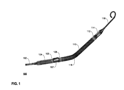
[0093] FIG. 1 depicts an exemplary intravascular blood pump 100
adapted for left heart support,
in accordance with aspects of the disclosure. In that regard, the
intravascular blood pump 100 includes
an elongate catheter 102, a motor 104, a cannula 110, a blood inflow cage 114
arranged at or near the
distal end 112 of the cannula 110, a blood outflow cage 106 arranged at or
near the proximal end 108
CA 03193572 2023- 3- 22
WO 2022/074136
PCT/EP2021/077732
9
of the can nula 110, and an optional atraumatic extension 116 arranged at the
distal end of the blood
inflow cage 114.
[0094]
Motor 104 is configured to rotatably drive an impeller (not shown),
thereby generating
suction sufficient to draw blood into cannula 110 through the blood inflow
cage 114, and to expel the
blood out of cannula 110 through the blood outflow cage 106. In that regard,
the impeller may be
positioned distal of the blood outflow cage 106, for example, within the
proximal end 108 of the cannula
110 or within a pump housing 107 coupled to the proximal end 108 of the
cannula 110. In some aspects
of the technology, rather than the impeller being driven by an on-board motor
104, the impeller may
instead be coupled to an elongate drive shaft which is driven by a motor
located external to the patient.
[0095]
Catheter 102 may house electrical lines coupling the motor 104 to one or
more electrical
controllers or other sensors. Alternatively, where the impeller is driven by
an external motor, an elongate
drive shaft may pass through catheter 102. Catheter 102 may also serve as a
conduit for one or more
wires (e.g., wire 502 of FIG. 5, described below) connecting the electrodes
described herein to one or
more controllers, power sources, etc. (e.g., as included in controller 302 of
FIG. 3, described below)
located outside the patient's body. Catheter 102 may also include a purge
fluid conduit, a lumen
configured to receive a guidewire, etc.
[0096]
The blood inflow cage 114 includes one or more apertures or openings
configured to allow
blood to be drawn into cannula 110 when the motor 104 is operating. Likewise,
blood outflow cage 106
includes one or more apertures or openings configured to allow blood to flow
from the cannula 110 out
of the intravascular blood pump 100. Blood inflow cage 114 and outflow cage
106 may be composed of
any suitable bio-compatible material(s). For example, blood inflow cage 114
and/or blood outflow cage
106 may be formed out of bio-compatible metals such as stainless steel,
titanium, or bioconnpatible
polymers such as polyurethane. In addition, the surfaces of blood inflow cage
114 and/or blood outflow
cage 106 may be treated in various ways, including, but not limited to
etching, texturing, or coating or
plating with another material. For example, the surfaces of blood inflow cage
114 and/or blood outflow
cage 106 may be laser textured.
[0097]
Cannula 110 may include a flexible hose portion. For example, cannula 110
may be
composed, at least in part, of a polyurethane material. In addition, cannula
110 may include a shape-
memory material. For example, cannula 110 may comprise a combination of a
polyurethane material
and one or more strands or coils of a shape-memory material such as Nitinol.
Cannula 110 may be
formed such that it includes one or more bends or curves in its relaxed state,
or it may be configured to
be straight in its relaxed state. In that regard, in the exemplary arrangement
shown in FIG. 1, the cannula
110 has a single pre-formed anatomical bend 118 based on the portion of the
left heart in which it is
intended to operate. Despite this bend 118, the cannula 110 may nevertheless
also be flexible, and may
thus be capable of straightening (e.g., during insertion over a guidewire), or
bending further (e.g., in a
patient whose anatomy has tighter dimensions). Further in that regard, cannula
110 may include a
shape-memory material configured to allow the cannula 110 to be a different
shape (e.g., straight or
mostly straight) at room temperatures, and to form bend 118 once the shape-
memory material is
exposed to the heat of a patient's body.
CA 03193572 2023- 3- 22
WO 2022/074136
PCT/EP2021/077732
[0098]
Atraumatic extension 116 may assist with stabilizing and positioning the
intravascular blood
pump 100 in the correct position in the patient's heart. Atraumatic extension
116 may be solid or tubular.
If tubular, atraumatic extension 116 may be configured to allow a guidewire to
be passed through it to
further assist in the positioning of the intravascular blood pump 100.
Atraumatic extension 116 may be
any suitable size. For example, atraumatic extension 116 may have an outer
diameter in the range of
4-8 Fr. Atraumatic extension 116 may be composed, at least in part, of a
flexible material, and may be
any suitable shape or configuration such as a straight configuration, a
partially curved configuration, a
pigtail-shaped configuration as shown in the example of FIG. 1, etc.
Atraumatic extension 116 may also
have sections with different stiffnesses. For example, atraumatic extension
116 may include a proximal
section that is stiff enough to prevent it from buckling, thereby keeping the
blood inflow cage 114 in the
desired location, and a distal section that is softer and has a lower
stiffness, thereby providing an
atraumatic tip for contact with a wall of the patient's heart and to allow for
guidewire loading. In such a
case, the proximal and distal sections of the atraumatic extension 116 may be
composed of different
materials, or may be composed of the same material, treated to provide
different stiffnesses.
[0099]
Notwithstanding the foregoing, as mentioned above, atraumatic extension
116 is an optional
structure. In that regard, the present technology may also be used with
intravascular blood pumps and
other intracardiac devices that include extensions of different types, shapes,
materials, and qualities.
Likewise, the present technology may be used with intravascular blood pumps
and other intracardiac
devices that have no distal extensions of any kind.
[0100]
Intravascular blood pump 100 may be inserted percutaneously. For example,
when used
for left heart support, intravascular blood pump 100 may be inserted via a
catheterization procedure
through the femoral artery or axillary artery, into the aorta, across the
aortic valve, and into the left
ventricle. Once positioned in this way, the intravascular blood pump 100 may
deliver blood from the
blood inflow cage 114, which may sit inside the left ventricle, through
cannula 110, to the blood outflow
cage 106, which may sit inside the ascending aorta. In some aspects of the
technology, intravascular
blood pump 100 may be configured such that bend 118 will rest against a
predetermined portion of the
patient's heart when the intravascular blood pump 100 is in a desired
location. Likewise, the atraumatic
extension 116 may be configured such that it rests against a different
predetermined portion of the
patient's heart when the intravascular blood pump 100 is in the desired
location.
[0101]
FIG. 2 depicts an exemplary intravascular blood pump 200 adapted for right
heart support,
in accordance with aspects of the disclosure. In that regard, the
intravascular blood pump 200 includes
an elongate catheter 202, a motor 204, a cannula 210, a blood inflow cage 214
arranged at or near the
proximal end 208 of the cannula 210, a blood outflow cage 206 arranged at or
near the distal end 212
of the cannula 210, and an optional atraumatic extension 216 arranged at the
distal end of the blood
outflow cage 206.
[0102]
As with the exemplary blood pump of FIG. 1, motor 204 is configured to
rotatably drive an
impeller (not shown), thereby generating suction sufficient to draw blood into
cannula 210 through the
blood inflow cage 214, and to expel the blood out of cannula 210 through the
blood outflow cage 206.
In that regard, the impeller may be positioned distal of the blood inflow cage
214, for example, within
CA 03193572 2023- 3- 22
WO 2022/074136
PCT/EP2021/077732
11
the proximal end 208 of the cannula 210 or within a pump housing 207 coupled
to the proximal end 208
of the cannula 210. Here as well, in some aspects of the technology, rather
than the impeller being
driven by an in-dwelling motor 204, the impeller may instead be coupled to an
elongate drive shaft which
is driven by a motor located external to the patient
[0103]
The cannula 210 of FIG. 2 may serve the same purpose, and may have the
same properties
and features described above with respect to cannula 110 of FIG. 1. However,
in the exemplary
arrangement shown in FIG. 2, the cannula 210 has two pre-formed anatomical
bends 218 and 220
based on the portion of the right heart in which it is intended to operate.
Here again, despite the existence
of bends 218 and 220, the cannula 210 may nevertheless also be flexible, and
may thus be capable of
straightening (e.g., during insertion over a guidewire), or bending further
(e.g., in a patient whose
anatomy has tighter dimensions). Further in that regard, cannula 210 may
include a shape-memory
material configured to allow the cannula 210 to be a different shape (e.g.,
straight or mostly straight) at
room temperatures, and to form bends 218 and/or 220 once the shape-memory
material is exposed to
the heat of a patient's body.
[0104]
The catheter 202 and atraumatic extension 216 of FIG. 2 serve the same
purpose and may
have the same properties and features described above with respect to catheter
102 and atraumatic
extension 116 of FIG. 1. Likewise, other than being located at opposite ends
of the cannula from those
of FIG. 1, the blood inflow cage 214 and blood outflow cage 206 of FIG. 2 are
similar to the blood inflow
cage 114 and blood outflow cage 106 of FIG. 1, and thus may have the same
properties and features
described above.
[0105]
Like the exemplary blood pump of FIG. 1, the intravascular blood pump 200
of FIG. 2 may
also be inserted percutaneously. For example, when used for right heart
support, intravascular blood
pump 200 may be inserted via a catheterization procedure through the femoral
vein, into the inferior
vena cava, through the right atrium, across the tricuspid valve, into the
right ventricle, through the
pulmonary valve, and into the pulmonary artery. Once positioned in this way,
the intravascular blood
pump 200 may deliver blood from the blood inflow cage 214, which may sit
inside the inferior vena cava,
through cannula 210, to the blood outflow cage 206, which may sit inside the
pulmonary artery.
[0106]
As described herein, the intravascular pump may be configured to assess
ventricular
volume (and thus cardiac performance and cardiac unloading) while the
intravascular blood pump or
other device remains within the patient's heart via one or more electrodes
that induce current and one
or more electrodes that measure voltage. FIG. 3 is a functional block diagram
of an exemplary system,
in accordance with aspects of this disclosure. In the example of FIG. 3, the
system 300 includes an
intravascular blood pump 318 and a controller 302. The intravascular blood
pump 318 may take any
form, including those shown in the exemplary intravascular blood pumps 100 and
200 of FIGS. 1 or 2,
respectively. As shown in the example of FIG. 3, the intravascular blood pump
318 of FIG. 3 may include
one or more pressure sensors 322 and a motor 324. The intravascular blood pump
318 may include an
attached electrode assembly patch 320 such as the electrode assembly patches
400, 600, 700, 800
shown in FIGS. 4A, 4B, 6A, 6B, 7A, 76, and 8.
CA 03193572 2023- 3- 22
WO 2022/074136
PCT/EP2021/077732
12
[0107] As described herein, the electrode assembly patch 320 may
include one or more electrodes.
For example, as shown in FIG. 40, the electrode assembly patch 400 may include
at least two electrodes
configured to provide (e.g., induce) a current (e.g., electrodes 454a and 454d
of FIG. 4D, the electrodes
of electrode tabs 606a and 606d of FIG. 6, the electrodes of electrode tabs
706a and 706d of FIG. 7,
and the electrodes 806a and 806d of FIG. 8, as described further below), and
at least two electrodes
configured to measure voltage (e.g., electrodes 454b and 454c of FIG. 40, the
electrodes of electrode
tabs 606b and 606c of FIG. 6, the electrodes of electrode tabs 706b and 706c
of FIG. 7, and the
electrodes 806b and 806c of FIG. 8, as described further below).
[0108] In some embodiments, one or more pressure sensors 322 may
include any suitable type of
pressure sensor or combination of pressure sensors configured to measure
pressure at or near the
electrodes of the electrode assembly patch 320. Thus, in some aspects of the
technology, the pressure
sensor(s) 322 may be a single pressure sensor positioned at or near the distal
end of the cannula (e.g.,
cannula 110 or 210). Likewise, in some aspects of the technology, the pressure
sensor(s) 322 may be
a combination of a pressure sensors whose readings may be combined to derive
an estimated pressure
in the vicinity of the set of electrodes of the electrode assembly patch 320.
[0109] In the example of FIG. 3, the controller 302 may include one
or more processors 304
coupled to memory 306 storing instructions 308 and data 310, a device
interface 312 with the
intravascular blood pump 318, a current source 314, a power source 316, and a
voltage measurement
unit 317. The device interface 312 may be any suitable type of interface
between controller 302 and
intravascular blood pump 318 that is capable of providing current from current
source 314 to the
electrodes of the electrode assembly patch 320, receiving voltage readings
from the electrodes of the
electrode assembly patch 320, receiving pressure readings from pressure
sensor(s) 322, and providing
power from power supply 316t0 motor 324. Current source 314 may be any device
capable of providing
a suitable current for performing conductance or admittance measurements. For
example, current
source 314 may be configured to provide a substantially constant alternating
current of 10 and 100 pA
at 20 kHz. As will be understood, in some aspects of the technology, current
source 314 and power
supply 316 may be implemented as a single unit configured to both power the
motor 324 and provide a
suitable current to the electrodes of the electrode assembly patch 320.
[0110] Controller 302 may take any form. In that regard, controller
302 may comprise a single
modular unit, or its components may be distributed between two or more
physical units. Controller 302
may further include any other components normally used in connection with a
computing device such
as a user interface. In that regard, controller 302 may have a user interface
that includes one or more
user inputs (e.g., buttons, touchscreen, keypad, keyboard, mouse, microphone,
etc.); one or more
electronic displays (e.g., a monitor having a screen or any other electrical
device that is operable to
display information, one or more lights, etc.); one or more speakers, chimes
or other audio output
devices; and/or one or more other output devices such as vibrating, pulsing,
or haptic elements.
[0111] The one or more processors 304 and memory 306 described herein
may be implemented
on any type of computing device(s), including customized hardware or any type
of general computing
device. Memory 306 may be of any non-transitory type capable of storing
information accessible by the
CA 03193572 2023- 3- 22
WO 2022/074136
PCT/EP2021/077732
13
processor(s) 304, such as a hard-drive, memory card, optical disk, solid-state
drive, tape memory, or
similar structure.
[0112]
Instructions 308 may include programming configured to receive and process
readings from
the set of electrodes 320 and the one or more pressure sensors 322. In that
regard, instructions 308
may include the programming necessary to calculate voltage drops and/or phase
shift (e.g., using
voltage measurement unit 317) between the voltage-reading electrodes of the
electrodes of the
electrode assembly patch 320 (e.g., electrodes 454b and 454c of FIG. 4D, the
electrodes of electrode
tabs 606b and 606c of FIG. 6, the electrodes of electrode tabs 706b and 706c
of FIG. 7, and the
electrodes 806b and 806c of FIG. 8, as described further below), calculate
conductance or admittance
based on the readings received from the electrodes of the electrode assembly
patch 320 and the one
or more pressure sensors 322, estimate ventricular volume based on conductance
or admittance
calculations, generate pressure-volume loops based on estimated ventricular
volume, generate
estimates of cardiac performance based on generated pressure-volume loops,
and/or generate
estimates of ventricular unloading provided by the operation of the
intravascular blood pump 318 based
on generated pressure-volume loops. Controller 302 may further be configured
to store readings from
the set of electrodes 320 and the one or more pressure sensors 322, and
calculations based thereon,
in memory 306. In some embodiments, the controller 302 also may be configured
to send readings from
the electrodes of the electrode assembly patch 320 and/or generated estimates
of ventricular unloading
or cardiac performance to an external device, such as to a user interface (not
shown) and/or to a cloud-
based storage devices where the readings and/or generated estimates may be
stored.
[0113]
Data 310 may include any relevant data for operating the intravascular
blood pump 318.
For example, data 310 may include lookup tables and other data relevant to
interpreting signals from
the intravascular blood pump 318, calibrating and/or interpreting the signals
of the electrodes of the
electrode assembly patch 320 or the one or more pressure sensors 322, etc.
[0114]
FIG. 4A depicts an exemplary electrode assembly patch 400, in accordance
with aspects
of the disclosure. As shown in FIG. 4D, the exemplary electrode assembly patch
400 is configured as a
multi-layered strip 404, extending longitudinally (e.g., in the direction of
line Y-Y) from a proximal end
402 to a distal end 410.
[0115]
In some embodiments, as shown in FIGS. 4A and 4B, the electrode assembly
patch 400
may include one or more tabs extending outwardly and away from the strip. For
example, one or more
tabs may extend outwardly and away from a first side of the strip in a first
direction and one or more
tabs may extend outwardly and away from a second, opposite side of the strip
in a second, opposite
direction. In some embodiments, the tabs may extend to the left and right of
the strip.
[0116]
As shown in FIGS. 4A and 4B, in some embodiments, the tabs may be
perpendicular to the
strip. In other embodiments, one or more tabs may extend at other suitable
angles relative to the strip.
For example, the tabs may extend 45 degrees relative to the latitudinal axis
of the strip. In some
embodiments, as shown in FIGS. 4A and 4B, the tabs may be positioned parallel
to one another. As will
be appreciated, in other embodiments, one or more tabs may extend in a
direction non-parallel to
another tab (or tabs as the case may be).
CA 03193572 2023- 3- 22
WO 2022/074136
PCT/EP2021/077732
14
[0117] As shown in FIG. 4A, the tabs labeled 406a, 406b, 4060, and
406d and extending to the
right of the strip 404 are electrode tabs. For purposes herein electrode tabs
include tabs in which an
electrode extends at least partially therein. As described herein, the
electrodes may induce a current in
some embodiments and/or measure voltage in other embodiments In some
embodiments, the tabs
labeled 408a and 408b and extending to the left of the strip are non-
conductive stabilizer tabs. In some
embodiments, the non-conductive stabilizer tabs may be used both to ensure
separation and proper
alignment of the electrode tabs (when wrapped around an intravascular device),
and to enhance
adhesion and stabilize the electrode assembly patch when it is being affixed
to a portion of an
intravascular blood pump or other device (e.g., using thermoforming, bonding,
gluing, etc.).
[0118] In some embodiments, as shown in FIG. 4E, when attached to the
intravascular device, the
electrode tabs (e.g., electrode tab 406a of FIG. 4E) are configured to wrap
around only a portion of an
intravascular device 470. That is, in such embodiments, the electrode tabs do
not encircle an entire
circumference of the device. In other words, in such embodiments, the
electrodes of the electrode
assembly patch do not form closed rings when the electrode assembly patch is
attached to the device
(e.g., a distal end of the electrode tab is spaced from the adjacent portion
of the strip).
[0119] Although the example of FIG. 4A depicts all of the electrode
tabs extending to the right of
strip 404, and all of the stabilizer tabs extending to the left of the strip
404, it will be understood that any
suitable arrangement may be used. For example, in some aspects of the
technology, the directions of
each tab may be reversed from what is shown in FIG. 4A. Likewise, in some
aspects of the technology,
the tabs labeled 406a, 406b, and 408b may each extend to the left of strip
404, and the tabs labeled
408a, 406c, and 406d may each extend to the right of strip 404.
[0120] Although the example of FIG. 4A depicts an electrode assembly
patch with both electrode
tabs and stabilizertabs, in other embodiments, the electrode assembly patch
may include only electrode
tabs. As will be appreciated, in such an example, the electrodes tabs may have
any suitable
arrangement relative to the strip.
[0121] As shown in FIG. 4A, the strip 404 may have a tapered section
at or near its proximal end
402. In such embodiments, the strip 404 may be wider at or near the proximal
end 402 than at the distal
end 410 (or another suitable portion of the strip). In some embodiments, the
wider portion at or near the
proximal end 402 may be used for welding or bonding external wires (e.g.,
wires 504 of FIG. 5) to
contacts located at or near the proximal end 402 (e.g., contacts 462a-462d of
FIG. 5). In cases where
one or more wires are welded to each contact , a further layer of non-
conductive material may be applied
over top of the welds to electrically insulate the exposed wires and/or the
weld from ambient fluids.
[0122] Although the exemplary electrode assembly patch 400 of FIG. 4A
is shown with four
electrode tabs, in some aspects of the technology, it may be implemented with
additional or fewer
electrode tabs (e.g., such that the total number of electrode tabs is 2, 6, 8,
10, 12, etc.). In addition,
although the exemplary electrode assembly patch 400 is shown in FIGS. 4C and
4D having four layers,
any other number of layers and arrangement of conductors may be employed.
[0123] It will be understood that the exemplary electrode assembly
patch 400 of FIG. 4A may be
adapted to any suitable intravascular blood pump, and that its dimensions may
be customized to
CA 03193572 2023- 3- 22
WO 2022/074136
PCT/EP2021/077732
whatever device it is applied to. In that regard, FIG. 4B depicts a copy of
the exemplary electrode
assembly patch 400 of FIG. 4A, annotated to show various features and
dimensions that may be
modified to adapt the assembly to different intravascular blood pumps or other
devices. For purposes of
illustration, each of the features and dimensions depicted in FIG. 4B will be
described below using the
assumption that the electrode assembly patch is to be applied (e.g.,
thermoformed, glued, bonded, etc.)
to the outer surface of a cannula (e.g., cannula 110 of FIG. 1) of an
intravascular blood pump. It is further
assumed that the cannula has a length of at least 70 mm and a diameter of
about 14 Fr (4.67 mm).
Although FIGS. 4A and 4B depict the same exemplary electrode assembly patch
400, for clarity, the
elements identified in FIG. 4A have not been identified again in FIG. 4B.
[0124]
Using the assumptions set forth above, the electrode assembly patch 400 of
FIG. 4B may
have a total length 428 of 70 mm. The proximal end 402 of the strip 404 may
have a contact patch with
a width 420 of 6 mm and length 422 of 2.5 mm, which then tapers down to a
width 442 of 3 mm. The
tapered section may have a length 424 of 2.5 mm, and a taper angle 426 of
approximately 149 .
[0125]
The four electrode tabs may each have a width 446 of 3 mm, and may be
arranged such
that the first and second tabs (406a and 406b of FIG. 4A) and the third and
fourth tabs (406c and 406d
of FIG. 4A) are spaced apart by a distance 436 of 3 mm, and such that the
second and third tabs (406b
and 406c of FIG. 4A) are separated by a distance 430 of 10 mm. As such, the
set of four electrode tabs
may span a total length 432 of 28 mm. In some aspects of the technology, it
may be desirable to
maximize the distance 430 between the second and third tabs (406b and 406c of
FIG. 4A). As such,
where the dimensions of the intravascular blood pump and/or the patient's
anatomy allows distance 430
to be increased, it may be advantageous to do so, provided that all four
electrode tabs may still fit within
the volume to be measured (e.g., a patient's left ventricle).
[0126]
The length 444 of each electrode tab may be configured such that the end
of each tab will
approach, but not overlap, the left edge of the strip when the tab is wrapped
around the outside of the
cannula. In that regard, given that a cannula with a diameter of 14 Fr will
have a circumference of
approximately 14.66 mm, and given that the strip has a width 442 of 3 mm, each
electrode tab may have
a length 444 of 11.5 mm, such that a gap of approximately 0.16 mm remains when
the tab is wrapped
around the cannula. It will be understood that avoiding overlap is not
essential to the present technology,
but may provide advantages in certain cases. For example, if the electrode
assembly patch 400 is
thermoformed to a portion of an intravascular blood pump, an overlap may cause
the end of the
electrode tab to melt together with a portion of the strip, which may cause a
short to form between an
electrode (e.g., electrode 454a of FIG. 4C) and one of the conductors for
another electrode (e.g., wires
456b, 456c, or 456d of FIG. 4C). Likewise, as the material of electrode
assembly patch 400 may not
adhere to itself as strongly as it adheres to the cannula (or whatever other
portion of the intravascular
blood pump it may be applied to), an overlap may create an area of weakness
where the tab may begin
to peel up and delaminate. Further, avoiding overlap may be desirable for
minimizing the overall
diameter of the intravascular blood pump and/or to achieve a smoother outer
profile when the electrode
assembly patch 400 is applied to the surface of the intravascular blood pump.
CA 03193572 2023- 3- 22
WO 2022/074136
PCT/EP2021/077732
16
[0127]
In the example of FIGS. 4A and 4B, the first stabilizer tab (408a of FIG.
4A) is positioned
such that it may fit between the distal ends of the first and second electrode
tabs (406a and 406b of
FIG. 4A) when the electrode assembly patch 400 is wrapped around the
intravascular blood pump, and
the second stabilizer tab (408b of FIG. 4A) is positioned such that it may fit
between the distal ends of
the third and fourth electrode tabs (406c and 406d of FIG. 4A). Thus, in the
present example, the length
440 of each stabilizer tab may be 5 mm and the width 434 may be 2.5 mm. Using
a width 434 of 2.5 mm
allows for 0.25 mm of space to remain between the edges of each stabilizer tab
and its two neighboring
electrode tabs. Here as well, leaving a space between the edges of the
stabilizer tab and its neighboring
electrode tabs may be advantageous for ensuring that no overlaps are created
during manufacturing
that may adversely impact the overall diameter and/or smoothness of the outer
profile, create weak
points in the bond between the electrode assembly patch 400 and the cannula,
etc.
[0128]
Although each of the electrode tabs are showing as having the same width
and length in
FIG. 4A, it will be appreciated that the width and/or length of the tabs may
vary from tab to tab (or
between subsets of tabs). Similarly, although each of the stabilizer tabs are
showing as having the same
width and length in FIG. 4A, it will be appreciated that the width and/or
length of the tabs may vary from
tab to tab. Also, although each of the electrode and each of the stabilizer
tabs are shown as having a
uniform width, in other embodiments, one or more tabs may a width that varies
between the proximal
and distal ends (see e.g., the electrode tabs in FIG. 6A). For purposes
herein, the proximal end of a tab
is the end of the tab closest to the strip.
[0129]
FIGS. 4C and 4D depict exemplary cross-sectional views of the electrode
assembly patch
of FIG. 4A, in accordance with aspects of the disclosure. More specifically,
FIG. 40 depicts an exemplary
cross-sectional view of the electrode assembly patch of FIG. 4A taken along
line X-X, and thus shows
a lateral cross-section spanning from a left edge 450 of strip 404 to a right
edge 452 of electrode tab
406a. FIG. 4D depicts an exemplary cross-sectional view of the electrode
assembly patch of FIG. 4A
taken along line Y-Y, and thus shows a longitudinal cross-section spanning
from the proximal end 402
to the distal end 410 of the electrode assembly patch of FIG. 4A.
[0130]
As shown in the example of FIG. 40, the electrode assembly patch may
include four
sandwiched layers (labeled 1-4 in FIGS. 40 and 4D). Layer 1 may be a non-
conductive (dielectric) layer
configured to adhere to a particular portion of the intravascular blood pump
(or other device), and to
electrically insulate the second layer from whatever surface the electrode
assembly patch is applied to.
For example, where the electrode assembly patch is to be applied to a flexible
cannula (e.g., cannula
110 of FIG. 1) of an intravascular blood pump (e.g., intravascular blood pump
100 of FIG. 1), layer 1
may be made from a polymer (e.g., a polyamide film) suitable for gluing,
bonding, or thermoforming to
the can nula.
[0131]
Layer 2 may contain wires 456a-456d, each of which runs between a contact
patch (e.g.,
contact patch 462a) near the proximal end 402 of the electrode assembly patch
and a respective
electrode (454a-454d). Wires 456a-456d may be formed from any suitable metal
or other conductive
material, such as platinum, gold, silver, copper, etc. As shown in FIG. 40,
each of the wires 456a-456d
may be spaced apart and separated by a non-conductive material (all white
portions of layers 1-4
CA 03193572 2023- 3- 22
WO 2022/074136
PCT/EP2021/077732
17
represent non-conductive material). In addition, non-conductive material may
be also be used to fill the
space between wire 456d and the left edge 450 of strip 404, and between 456a
and the right edge of
strip 404, such that wires 456a and 456d will also remain insulated from
ambient fluids.
[0132]
In some aspects of the technology, one or more of the portions of non-
conductive material
in layer 2 may result from the insertion of non-conductive strips prior to
fusing the layers of the electrode
assembly patch together (e.g., using thermoforming). Likewise, in some aspects
of the technology,
where the layers of the electrode assembly patch are fused using
thermoforming, one or more of the
portions of non-conductive material in layer 2 may result from non-conductive
material melting and
flowing into layer 2 from one or more adjacent layers (e.g., layer 1 or 3)
during thermoforming. Here as
well, the non-conductive material may be a polymer (e.g., a polyamide) or
other suitable non-conductive
material, including any of the non-conductive materials used in other layers.
[0133]
Layer 3 may be another non-conductive layer configured to electrically
insulate the wires
456a-456d from layer 4, except where a conductive bridge is provided to
connect a given one of wires
(e.g., wire 456a) to its respective contact patch (e.g., contact patch 462a)
or its respective electrode
(e.g., electrode 454a). For example, as shown in FIGS. 4C and 40, a conductive
bridge 458a is provided
in a portion of layer 3 near electrode tab 406a in order to electrically
connect wire 456a to electrode
454a. Likewise, as shown in FIG. 4D, a conductive bridge 460a is provided in a
portion of layer 3 near
proximal end 402 to electrically connect wire 456a to contact patch 462a. Here
as well, the conductive
bridges (e.g. 458a, 460a) may be formed from any suitable metal or other
conductive material, such as
platinum, gold, silver, copper, etc.
[0134]
As above, one or more of the portions of non-conductive material in layer
3 may result from
the insertion of non-conductive strips prior to fusing the layers of the
electrode assembly patch together
(e.g., using thermoforming). Likewise, in some aspects of the technology,
where the layers of the
electrode assembly patch are fused using thermoforming, one or more of the
portions of non-conductive
material in layer 3 may result from non-conductive material melting and
flowing into layer 3 from one or
more adjacent layers (e.g., layer 2 or 4) during thermoforming. Here as well,
the non-conductive material
of layer 3 may be a polymer (e.g., a polyamide) or other suitable non-
conductive material, including any
of the non-conductive materials used in other layers.
[0135]
Layer 4 may contain the electrodes 454a-454d, each of which may be
arranged to coincide
with a corresponding electrode tab (406a-406d). As shown in FIG. 4D, each of
the electrodes 454a-
454d may be spaced apart and separated by a non-conductive material. Likewise,
FIG. 4C shows a
small amount of non-conductive material between the left end of electrode 454a
and the left edge 450
of strip 404, and another small amount of non-conductive material between the
right end of electrode
454a and the right edge 452 of electrode tab 406a. However, in some aspects of
the technology, the
electrode 454a may run the entire length from the left edge 450 of strip 404
to the right edge 452 of
electrode tab 406a.
[0136]
The top surface of each electrode 454a-454d may be exposed such that it
can be used to
provide a current to an ambient fluid (e.g., the blood within a patient's left
ventricle), or sense voltage
from that ambient fluid. Here as well, any suitable metal or other conductive
material may be used for
CA 03193572 2023- 3- 22
WO 2022/074136
PCT/EP2021/077732
18
electrodes 454a-454d, such as platinum, gold, silver, copper, etc. In
addition, electrodes 454a-454d
may include a combination of conductive materials. For example, in some
aspects of the technology,
the electrodes 454a-454d may be formed from gold, and then coated or plated
with a thin (e.g., a 100
nm) top layer of platinum.
[0137]
As above, one or more of the portions of non-conductive material in layer
4 may result from
the insertion of non-conductive strips prior to fusing the layers of the
electrode assembly patch together
(e.g., using thermoforming). Likewise, in some aspects of the technology,
where the layers of the
electrode assembly patch are fused using thermoforming, one or more of the
portions of non-conductive
material in layer 4 may result from non-conductive material melting and
flowing into layer 4 from an
adjacent layer (e.g., layer 3) during thermoforming. Here as well, the non-
conductive material of layer 4
may be a polymer (e.g., a polyamide) or other suitable non-conductive
material, including any of the
non-conductive materials used in other layers.
[0138]
Each of layers 1-4 may be any suitable thickness. For example, in some
aspects of the
technology, each layer may have a thickness of 5 pm, such that the electrode
assembly patch may have
a total thickness of 20 pm. Likewise, in some aspects of the technology, each
layer may have a thickness
between 1-10 pm. However, while FIGS. 4C and 4D show layers of equal
thickness, in some aspects
of the technology, one or more of the layers may be of a different thickness
than the others. Likewise,
although the example of FIGS. 4C and 4D show layers which have a constant
thickness, in some
aspects of the technology, the thickness of a layer may vary from left to
right or from proximal to distal.
For example, in some aspects of the technology, layers 1 and 2 may be formed
using a first pre-formed
sheet having a conductive film bonded to a non-conductive (dielectric) base
which is etched such that
only selected patches of the conductive film remain, and layers 3 and 4 may
similarly be formed from a
second pre-formed sheet of similar composition. In such cases, if the two
sheets are combined using
thermoforming, the non-conductive material from layers 1 and 3 may flow into
adjacent layers 2 and 4
to bond the two sheets together and seal against any conductive material that
remains in layers 2 and
4, resulting in the thickness of the electrode assembly patch varying slightly
in areas with and without
conductive film.
[0139]
In addition, the thickness and materials of layers 1-4 may be selected
such that suitable
material properties are obtained for a given application. For example, where
the electrode assembly
patch is to be affixed to a flexible section of an intravascular blood pump
such as the cannula (e.g.,
cannula 110 of FIG. 1), relatively thin layers may be used (e.g., 5 pm) and
relatively flexible materials
may be used for the non-conductive portions (e.g., polyamides) such that the
entire electrode assembly
patch will be capable of flexing with the section of the intravascular blood
pump to which it is affixed.
[0140]
FIG. 5 depicts an exemplary application of the electrode assembly patch of
FIG. 4A to a
portion of the exemplary blood pump of FIG. 1, in accordance with aspects of
the disclosure. In that
regard, FIG. 5 depicts a wire 502 routed along the outside of motor 104, along
one of the struts of the
blood outflow cage 106, where it fans out to individual wires 504, each of
which connects to a different
one of contact 462a-462d. In some aspects of the technology, wire 502 may
travel within the elongate
catheter 102 (not visible in FIG. 5), and may exit at a point near the
proximal end of motor 104. As noted
CA 03193572 2023- 3- 22
WO 2022/074136
PCT/EP2021/077732
19
above, a coating or layer of non-conductive material may be applied over top
of contact patches 462a-
462d to insulate them from ambient fluids. Likewise, in some aspects of the
technology, a coating or
layer of non-conductive material may also be applied over top of wires 504. In
some aspects of the
technology, the non-conductive material may be a polymer sleeve (e.g., a
polyamide sleeve) that is
thermoformed over top of wires 504 and/or contact 462a-462d.
[0141] As will be appreciated, the electrode assembly patch may be
joined to contacts located at
other suitable locations of the intravascular pump. For example, in one
embodiment, the electrode
assembly patch may extend over at least a portion of the outflow cage 106 and
extend into the catheter
of the intravascular blood pump. In such an embodiment, the contacts and the
electrode assembly patch
may be placed inside the catheter of the intravascular blood pump for
connection.
[0142] In the example of FIG. 5, the electrode assembly patch of FIG.
4A has been applied to the
flexible cannula 110. As can be seen, the proximal end 402 of the strip 404
may be positioned near the
proximal end 108 of the cannula 110, and the distal end 410 of the strip 404
may be positioned near the
distal end 112 of the cannula 110. For example, in some embodiments, the
distal end may be positioned
near an inlet inflow cage (not shown) attached to the distal end of the
cannula. In addition, each of the
electrode tabs 406a-406d are arranged distal of the pre-formed anatomical bend
118 in cannula 110. In
some aspects of the technology, the intravascular blood pump 100 may be
configured such that the
anatomical bend 118 will sit at or near the aortic valve. In such cases,
arranging the electrode tabs 406a-
406d distal of the pre-formed anatomical bend 118 may cause them to be
positioned within a patient's
left ventricle when the pump is in operation, such that they can be used to
measure left ventricular
volume.
[0143] In some aspects of the technology, the electrode assembly
patch may be configured and/or
applied such that the wires 456a-456d within strip 404 run along the side of
the cannula (as opposed to
running on the outside or the inside of anatomical bend 118). Although the
electrode assembly patch
may be formed to be thin and flexible (as described above), affixing it in
this way may reduce stress on
the wires 456a-456d which may lead to breakage, and/or may reduce the
likelihood of the electrode
assembly patch delaminating due to bending of the cannula 110.
[0144] The electrode assembly patch may be affixed to cannula 110
using any suitable method of
bonding, gluing, thermoforming, etc. For example, in some aspects of the
technology, the electrode
assembly patch of FIGS. 4A-4D may be formed using one or more polyamides as
the non-conductive
material, gold as the conductive material (with or without a platinum plating
on the top surface of
electrodes 454a-454d), and may be thermoformed to the outer surface of cannula
110. In such a case,
the electrode assembly patch may be laid over top of the cannula 110, covered
with heat shrink tubing,
and heated until the polyamide in layer 1 (and potentially some or all of the
polyamide at the edges of
other layers) fuses with the material of the cannula 110 (e.g., polyurethane).
[0145] FIG. 6A depicts another exemplary electrode assembly patch
600, in accordance with
aspects of the disclosure. Here as well, the exemplary electrode assembly
patch 600 may be configured
as a multi-layered strip 604, which may have any suitable number and
configuration of layers, including
a configuration based on that which is discussed above with respect to FIGS.
4C and 4D. Like the
CA 03193572 2023- 3- 22
WO 2022/074136
PCT/EP2021/077732
example of FIG. 4A, strip 604 extends longitudinally from a proximal end 602
to a distal end 610, with a
series of electrode tabs 606a, 606b, 606c, and 606d extending perpendicularly
to the right, and two
stabilizer tabs 608a and 608b extending to the left. In the example of FIG.
6A, the non-conductive
stabilizer tabs are not positioned in between the electrode tabs when wrapped
around the medical
device. In that regard, the stabilizer tabs may function to stabilize the
electrode assembly patch when it
is being applied to a portion of an intravascular blood pump or other device
(e.g., using thermoforming,
bonding, gluing, etc.), and enhance adhesion, although not functioning as a
separator tab. Similar to
FIG. 4A, the strip 604 has a tapered section near its proximal end 602, which
results in the strip 604
having a wider portion at proximal end 602 that may be used for welding or
bonding external wires to
contact located thereon.
[0146]
Here as well, although the example of FIG. 6A depicts all of the electrode
tabs extending to
the right of strip 604, and all of the stabilizer tabs extending to the left
of the strip 604, it will be understood
that any suitable arrangement may be used. For example, in some aspects of the
technology, the
directions of each tab may be reversed from what is shown in FIG. 6A.
Likewise, in some aspects of the
technology, the tabs labeled 606a, 606b, and 608b may each extend to the left
of strip 604, and the tabs
labeled 608a, 606c, and 606d may each extend to the right of strip 404.
Further, although the exemplary
electrode assembly patch 600 of FIG. 6A is shown with four electrode tabs, in
some aspects of the
technology, it may be implemented with more or fewer additional sets of
electrode tabs (e.g., such that
the total number of electrode tabs is 2, 6, 8, 10, 12, etc.). Again, as with
the above, although the electrode
assembly patch is shown with two stabilizer tabs, it will be appreciated that
the electrode assembly patch
need not include stabilizer tabs, or may have more or fewer tabs. Also, the
positions of the tabs along
the longitudinal axis of the strip may vary in other embodiments.
[0147]
It will be understood that the exemplary electrode assembly patch 600 of
FIG. 6A may be
adapted to any suitable intravascular blood pump, and that its dimensions may
be customized to
whatever device it is applied to. In that regard, FIG. 6B depicts a copy of
the exemplary electrode
assembly patch 600 of FIG. 6A, annotated to show various features and
dimensions that may be
modified to adapt the assembly to different intravascular blood pumps or other
devices. For purposes of
illustration, each of the features and dimensions depicted in FIG. 6B will be
described below using the
assumption that the electrode assembly patch is to be applied (e.g.,
thermoformed, glued, bonded, etc.)
to the outer surface of a cannula (e.g., cannula 110 of FIG. 1) of an
intravascular blood pump. It is further
assumed that the cannula has a length of at least 55 mm and a diameter of
about 14 Fr (4.67 mm).
Although FIGS. 6A and 6B depict the same exemplary electrode assembly patch
600, for clarity, the
elements identified in FIG. 6A have not be identified again in FIG. 6B.
[0148]
Using the assumptions set forth above, the electrode assembly patch 600 of
FIG. 6B may
have a total length 628 of 55 mm. The proximal end of the strip may have a
contact patch with a width
620 of 6 mm and length 622 of 2.5 mm, which then tapers down to a width 638 of
3 mm. The tapered
section may have a length 624 of 2.5 mm, and a taper angle 626 of
approximately 149 .
[0149]
The four electrode tabs may each have a width 642 of 3 mm, and may be
arranged such
that the first and second tabs (606a and 606b of FIG. 6A) and the third and
fourth tabs (606c and 606d
CA 03193572 2023- 3- 22
WO 2022/074136
PCT/EP2021/077732
21
of FIG. 6A) are spaced apart by a distance 644 of 3 mm, and such that the
second and third tabs (606b
and 606c of FIG. 6A) are separated by a distance 632 of 10 mm. As such, the
set of four electrode tabs
may span a total length 634 of 28 mm. Here as well, in some aspects of the
technology, it may be
desirable to maximize the distance 632 between the second and third tabs (606b
and 606c of FIG. BA)
As such, where the dimensions of the pump and/or the patient's anatomy allows
distance 632 to be
increased, it may be advantageous to do so, provided that all four electrode
tabs may still fit within the
volume to be measured (e.g., a patient's left ventricle).
[0150] As in FIG. 4B, the length 640 of each electrode tab may be
configured such that the end of
each tab will approach, but not overlap, the left edge of the strip when the
tab is wrapped around the
outside of the cannula. In that regard, given that a cannula with a diameter
of 14 Fr will have a
circumference of approximately 14.66 mm, and given that the strip has a width
638 of 3 mm, each
electrode tab may have a length 640 of 11.5 mm, such that a gap of
approximately 0.16 mm remains
when the tab is wrapped around the cannula. Here as well, it will be
understood that avoiding overlap is
not essential to the present technology, but may provide advantages in certain
cases, as discussed
above.
[0151] In the example of FIGS. 6A and 6B, the first stabilizer tab
(608a of FIG. 6A) is positioned
proximal of the first electrode tab (606a of FIG. 6A), and the second
stabilizer tab (608b of FIG. 6A) is
positioned between the second and third electrode tabs (606b and 606c of FIG.
6A) such that it may
stabilize and reinforce adhesion of electrode assembly patch in the area
between the second and third
electrode tabs. As the stabilizer tabs of FIGS. 6A and 6B do not need to fit
within the distance 644
between the first and second electrode tabs or between the third and fourth
electrode tabs, they may
have a broader range of dimensions than those of FIGS. 4A and 4B. In this
example, it is assumed that
each stabilizer tab has a length 636 of 5 mm and a width 630 of 3 mm.
[0152] As shown in FIGS. 6A and 6B, each of the stabilizer tabs 608a,
608b and each of the
electrode tabs 606a-606d have curved sections (e.g., 646) where they join with
strip 604. In some
embodiments, rounding the corners in this way may reduce the chance that
tearing and/or delamination
of the electrode assembly patch may occur at these junctions. Any suitable
profile may be used in these
curved sections. For example, in some aspects of the technology, the curved
sections may have a
constant radius (e.g., 1 mm).
[0153] FIG. 7A depicts a further exemplary electrode assembly patch
700, in accordance with
aspects of the disclosure. Here as well, the exemplary electrode assembly
patch 700 may be configured
as a multi-layered strip 704, which may have any suitable number and
configuration of layers, including
a configuration based on that which is discussed above with respect to FIGS.
4C and 4D. In the example
of FIG. 7A, strip 704 extends longitudinally from a proximal end 702 to a
distal end 708, with a series of
electrode tabs 706a, 706b, 706c, and 706d, each of which extends
perpendicularly to strip 704 in both
the left and the right direction. As with the above, in other embodiments, the
tabs may extend at other
suitable angles relative to the strip and to other tabs. As shown in the
example of FIG. 7A, the strip 704
may be wider in the section at or near the proximal end of the strip (e.g.,
proximal the first electrode strip
706a), which may be helpful for welding or bonding external wires to contact
patches located thereon.
CA 03193572 2023- 3- 22
WO 2022/074136
PCT/EP2021/077732
22
[0154]
Unlike the exemplary electrode assemblies 400 and 600 of FIGS. 4A and 6A,
the wider
portion of strip 704 at proximal end 702 directly abuts the first electrode
strip 706a. This may result in
the exemplary electrode assembly patch of 700 being shorter overall than the
exemplary electrode
assemblies 400 and 600 of FIGS. 4A and 6A, which may be advantageous in
instances where the
electrode assembly patch needs to be affixed to a shorter portion of an
intravascular blood pump or
other device, where wires to be connected to each contact patch are routed
within a lumen or a wall of
the cannula (e.g., cannula 110 of FIG. 1), etc. In contrast, the exemplary
electrode assemblies 400 and
600 of FIGS. 4A and 6A may be advantageous where the electrode tabs (e.g.,
tabs 406a-406d of FIG.
4A, tabs 606a-606d of FIG. 6A) need to be positioned a longer distance from
where the wires to be
connected to each contact patch protrude from the catheter (e.g., catheter 102
of FIG. 1), as the portion
of the strip (e.g., strip 404 of FIG. 4A, strip 604 of FIG. 6A) between the
proximal end (e.g., proximal end
402 of FIG. 4A, proximal end 602 of FIG. 6A) and the first electrode tab
(e.g., electrode tab 406a of FIG.
4A, electrode tab 606a of FIG. 6A) may be lower-profile, more flexible, more
durable, and/or easier to
affix to the cannula (e.g., cannula 110 of FIG. 1) than if a standard wire
(e.g., wire 502) were to be affixed
to the cannula.
[0155]
Although the example of FIG. 7A depicts all of the electrode tabs
extending both to the left
and the right of strip 704, any suitable arrangement may be used. For example,
in some aspects of the
technology, all of the tabs may extend only to the right, or only to the left.
Likewise, in some aspects of
the technology, the tabs labeled 706a and 706b may each extend to the right of
strip 704, and the tabs
labeled 706c and 706d may each extend to the left of strip 704, or vice versa.
Further, although the
exemplary electrode assembly patch 700 of FIG. 7A is shown with four electrode
tabs, in some aspects
of the technology, it may be implemented with more or fewer sets of electrode
tabs (e.g., such that the
total number of electrode tabs is 2, 6, 8, 10, 12, etc.).
[0156]
It will be understood that the exemplary electrode assembly patch 700 of
FIG. 7A may be
adapted to any suitable intravascular blood pump, and that its dimensions may
be customized to
whatever device it is applied to. In that regard, FIG. 7B depicts a copy of
the exemplary electrode
assembly patch 700 of FIG. 7A, annotated to show various features and
dimensions that may be
modified to adapt the assembly to different intravascular blood pumps or other
devices. For purposes of
illustration, each of the features and dimensions depicted in FIG. 7B will be
described below using the
assumption that the electrode assembly patch is configured to be applied
(e.g., thermoformed, glued,
bonded, etc.) to the outer surface of a cannula (e.g., cannula 110 of FIG. 1)
of an intravascular blood
pump. It is further assumed that the cannula has a length of at least 30 mm
and a diameter of about 14
Fr (4.67 mm). Although FIGS. 7A and 7B depict the same exemplary electrode
assembly patch 700, for
clarity, the elements identified in FIG. 7A have not be identified again in
FIG. 7B.
[0157]
Using the assumptions set forth above, the electrode assembly patch 700 of
FIG. 7B may
have a total length 730 of 30 mm. The proximal end of the strip may have a
contact patch with a width
720 of 4 mm and length 722 of 2 mm.
[0158]
The four electrode tabs may each have a width 726 of 3 mm, and may be
arranged such
that the first and second tabs (706a and 706b of FIG. 7A) and the third and
fourth tabs (706c and 706d
CA 03193572 2023- 3- 22
WO 2022/074136
PCT/EP2021/077732
23
of FIG. 7A) are spaced apart by a distance 724 of 3 mm, and such that the
second and third tabs (706b
and 706c of FIG. 7A) are separated by a distance 728 of 10 mm. Here as well,
in some aspects of the
technology, it may be desirable to maximize the distance 728 between the
second and third tabs (706b
and 706c of FIG. 7A). As such, where the dimensions of the pump and/or the
patient's anatomy allows
distance 728 to be increased, it may be advantageous to do so, provided that
all four electrode tabs
may still fit within the volume to be measured (e.g., a patient's left
ventricle).
[0159]
Each electrode tab may extend to the right and the left of the strip by a
distance 732 of 5.5
mm. Here as well, this distance 732 may be chosen such that the ends of each
tab will approach each
other, but not overlap. In that regard, given that a cannula with a diameter
of 14 Fr will have a
circumference of approximately 14.66 mm, and given that the strip has a width
734 of 3 mm, each
electrode tab may extend to the right and to the left by a distance 732 of 5.5
mm, such that a gap of
approximately 0.66 mm remains when the tab is wrapped around the cannula. Here
as well, it will be
understood that avoiding overlap is not essential to the present technology,
but may provide advantages
in certain cases, as discussed above.
[0160]
Although patches have been shown and described as having tabs into which
the electrodes
may extend, it will be appreciated, that the electrode assembly patch may
include only a strip, as shown
in FIG. 8, with the electrodes extending into different regions of the strip.
For example, as shown in FIG.
8, the electrode assembly patch 800 may include four electrodes (806a-806d).
In some embodiments,
the strip 804 may have a uniform thickness between the proximal end 802 and
distal end 808 that is
larger than that of the strips shown in the other illustrative patches (see,
e.g., FIGS. 4A and 6A). As with
the above, the distance between the electrodes may be maintained relative to
one another via the
electrode assembly patch 800 and may be similar to that noted above with
respect to the electrode
assembly patches with tabs. The length of the electrodes also may be the same
as the electrodes
extending into the electrode tabs shown in the illustrative patches above.
[0161]
From the foregoing and with reference to the various figures, those
skilled in the art will
appreciate that certain modifications can also be made to the present
disclosure without departing from
the scope of the same. While several aspects of the disclosure have been shown
in the figures, it is not
intended that the disclosure be limited thereto, as it is intended that the
disclosure be as broad in scope
as the art will allow and that the specification be read likewise. Therefore,
the above description should
not be construed as limiting, but merely as exemplifications of particular
aspects of the present
technology.
[0162]
In some embodiments, the electrode assembly patch may be configured to
form at least a
portion of the cannula of the intravascular blood pump. For example, in some
embodiments, the
electrode assembly patch may form the outer layer of the cannula of the
intravascular blood pump. In
such embodiments. The electrode assembly patch may be wrapped, rolled, or
otherwise placed around
a support structure. In one embodiment, the support structure may include one
or more strands or coils
of a shape-memory material, such as Nitinol. In some embodiments, the cannula
may include a
multilayered construction including a polyurethane inner layer, a layer formed
of the support structure
(e.g., Nitinol coils) and an outer layer formed of the electrode assembly
patch. In some embodiments,
CA 03193572 2023- 3- 22
WO 2022/074136
PCT/EP2021/077732
24
the non-conductive layer of the electrode assembly patch also may comprise
polyurethane as non-
conductive material.
EXEMPLARY IMPLEMENTATIONS
[0163] As already described, the technology described herein may be
implemented in various
ways. In that regard, the foregoing disclosure is intended to include, but not
be limited to, the systems,
methods, and combinations and subcombinations thereof that are set forth in
the following categories
of exemplary implementations.
[0164] Category A:
Al. An electrode assembly patch attachable to an intravascular device, the
electrode assembly
patch comprising:
a strip extending from a proximal end to a distal end;
a first electrode tab extending outwardly and away from the strip, the first
electrode tab
configured to provide a current to an ambient fluid;
a second electrode tab spaced from the first electrode tab, the second
electrode tab extending
outwardly and away from the strip, the second electrode tab configured to
measure voltage in the
ambient fluid;
a third electrode tab spaced from the second electrode tab, the third
electrode tab extending
outwardly and away from the strip, the third electrode tab configured to
measure voltage in the ambient
fluid; and
a fourth electrode tab spaced from the third tab, the fourth electrode tab
extending outwardly
and away from the strip, the fourth electrode tab configured to provide a
current to the ambient fluid.
A2. The electrode assembly patch of Al, wherein the first, second, third, and
fourth electrode
tabs extend outwardly and away from a first side of the strip in a first
direction.
A3. The electrode assembly patch of A2, further comprising:
a first stabilizing tab extending outwardly and away from a second side of the
strip in a second
direction opposite the first direction; and
a second stabilizing tab spaced from the first stabilizing tab and extending
outwardly away from
the strip in the second direction.
A4. The electrode assembly patch of A3, wherein the first stabilizing tab is
positioned laterally
in between the first and second electrode tabs.
A5. The electrode assembly patch of A4, wherein the second stabilizing tab is
positioned
laterally between the third and fourth electrode tabs.
CA 03193572 2023- 3- 22
WO 2022/074136
PCT/EP2021/077732
A6. The electrode assembly patch of one of Al to A5, wherein the electrode
assembly patch is
configured to be flexible.
A7. The electrode assembly patch of one of Al to A6, wherein the electrode
assembly patch is
configured to have a two-dimensional configuration in an undeployed state and
wherein the electrode
assembly patch is further configured to have a three-dimensional configuration
in a deployed state.
A8. The electrode assembly patch of Al to A7, wherein each of the first,
second, third, and
fourth electrode tab includes an electrode extending in the tab.
A9. The electrode assembly patch of A8, wherein the electrode includes one or
both of gold or
platinum.
A10. The electrode assembly patch of one of Al to A8, wherein the second tab
is spaced apart
from the first tab by a first distance, the third tab is spaced apart from the
second tab by a second
distance, and the fourth tab is spaced apart from the third tab by the first
distance.
All. The electrode assembly patch of Al 0, wherein the second distance is
greater than the first
and third distances.
Al2. The electrode assembly patch of one of A3 to All, wherein each of the
first, second, third
and fourth electrode tabs and each of the first and second stabilizing tabs
extend perpendicular to the
strip.
A13. The electrode assembly patch of one of A3 to Al2, wherein a width of the
first stabilizing
tab is less than or equal to a first lateral distances between the first and
second electrode tabs and
wherein a width of the second stabilizing tab is less than or equal to a
second lateral distance between
the third and fourth electrode tabs.
A14. The electrode assembly patch of one of Al to A13, wherein the patch
includes four layers,
each layer having a thickness of 5 pm.
[0165] Catedory B:
B15. A system for determining an admittance or conductance, the system
comprising:
an intravascular device configured to be inserted into a patient's heart; and
a flexible electrode assembly patch attached to at least a portion of the
intravascular device,
wherein the flexible electrode assembly patch includes two or more electrodes
configured to determine
an admittance and/or conductance.
CA 03193572 2023- 3- 22
WO 2022/074136
PCT/EP2021/077732
26
B16. The system of B15, wherein the flexible electrode assembly patch
includes:
a strip extending from a proximal end to a distal end;
a first electrode tab extending outwardly and away from the strip, the first
electrode tab
configured to provide a current to an ambient fluid;
a second electrode tab spaced from the first electrode tab, the second
electrode tab extending
outwardly and away from the strip, the second electrode tab configured to
measure voltage in the
ambient fluid;
a third electrode tab spaced from the second electrode tab, the third
electrode tab extending
outwardly and away from the strip, the third electrode tab configured to
measure voltage in the ambient
fluid; and
a fourth electrode tab spaced from the third tab, the fourth electrode tab
extending outwardly
and away from the strip, the fourth electrode tab configured to provide a
current to the ambient fluid.
B17. The system of B16, wherein the first, second, third, and fourth electrode
tabs extend
outwardly and away from a first side of the strip in a first direction.
B18. The system of B17, further comprising:
a first stabilizing tab extending outwardly and away from a second side of the
strip in a second
direction opposite the first direction; and
a second stabilizing tab spaced from the first stabilizing tab and extending
outwardly away from
the strip in the second direction.
B19. The system of B15 to B18, wherein the flexible electrode assembly patch
includes a strip
having a proximal end and a distal end.
B20. The system of one of B15 to B19, further comprising:
a controller electrically connected to the electrode assembly patch, the
controller comprising:
a current source;
a memory; and
one or more processors coupled to the memory and configured to:
provide an alternating current to electrodes of the first electrode tab and
the
fourth electrode tab;
measure voltages through electrodes of the second electrode tab and the third
electrode tab; and
determine an admittance or a conductance based on the measured voltages of
the second tab and the third tab.
[0166] Cateciory C:
C21. A system for determining an admittance or conductance, the system
comprising:
CA 03193572 2023- 3- 22
WO 2022/074136
PCT/EP2021/077732
27
an intravascular device configured to be inserted into a patient's heart; and
an electrode assembly patch attached to at least a portion of the
intravascular device, wherein
the electrode assembly patch includes a multi-layered construction comprising:
a first non-conductive layer configured to adhered to the portion of the
intravascular
device;
a second layer having one or more wires;
a third non-conductive layer configured to electrically insulate the one or
more wires;
and
a fourth layer including one or more electrodes.
C22. The system of C21, wherein the first non-conductive layer may be formed
from a polymer
material configured to be glued, bonded and/or thermoformed to the portion of
the intravascular device.
C23. The system of C21 or C22, wherein each of the one or more wires are
spaced apart by a
non-conductive material.
C24. The system of one of C21 to C23, wherein the one or more wires are formed
from a
conductive material.
C25. The system of C24, wherein the conductive material includes platinum,
gold, silver, and/or
copper.
026. The system of one of 021 to C25, wherein the one or more electrodes in
the fourth layer
are at least partially exposed.
027. The system of one of 021 to 026, wherein the multi-layered construction
includes four
sandwiched layers.
C28. The system of one of C21 to C27, wherein the layers are glued, bonded,
and/or
thermoformed together.
C29. The system of one of C21 to C28, wherein the electrode assembly patch
includes:
a strip extending from a proximal end to a distal end;
a first electrode tab extending outwardly and away from the strip, the first
electrode tab
configured to provide a current to an ambient fluid;
a second electrode tab spaced from the first electrode tab, the second
electrode tab extending
outwardly and away from the strip, the second electrode tab configured to
measure voltage in the
ambient fluid;
CA 03193572 2023- 3- 22
WO 2022/074136
PCT/EP2021/077732
28
a third electrode tab spaced from the second electrode tab, the third
electrode tab extending
outwardly and away from the strip, the third electrode tab configured to
measure voltage in the ambient
fluid; and
a fourth electrode tab spaced from the third tab, the fourth electrode tab
extending outwardly
and away from the strip, the fourth electrode tab configured to provide a
current to the ambient fluid.
C30. The system of C29, wherein the first, second, third, and fourth electrode
tabs extend
outwardly and away from a first side of the strip in a first direction.
C31. The system of C30, further comprising:
a first stabilizing tab extending outwardly and away from a second side of the
strip in a second
direction opposite the first direction; and
a second stabilizing tab spaced from the first stabilizing tab and extending
outwardly away from
the strip in the second direction.
C32. The system of one of C31 to C31, wherein the electrode assembly patch
includes a strip
having a proximal end and a distal end.
C33. The system of C16, further comprising:
a controller electrically connected to the electrode assembly patch, the
controller comprising:
a current source;
a memory; and
one or more processors coupled to the memory and configured to:
provide an alternating current to electrodes of the first electrode tab and
the fourth
electrode tab;
measure voltages through electrodes of the second electrode tab and the third
electrode tab; and
determine an admittance or a conductance based on the measured voltages of the
second tab and the third tab.
[0167] Category D:
D34. A method of forming a system for determining an admittance or
conductance, the method
comprising:
rolling and/or wrapping a flexible electrode assembly patch to at least a
portion of an
intravascular device configured to be inserted into a patient's heart; and
attaching the flexible electrode assembly patch to the portion of the
intravascular device.
D35. The method of D34, wherein the step of attaching includes, thermoforming
the flexible
electrode assembly patch to the portion of the intravascular device.
CA 03193572 2023- 3- 22
WO 2022/074136
PCT/EP2021/077732
29
D36. The method of D34 or 035, wherein the flexible electrode assembly patch
includes a multi-
layered construction.
D37. The method of one of D34 to D36, wherein the flexible electrode assembly
patch includes:
a strip extending from a proximal end to a distal end;
a first electrode tab extending outwardly and away from the strip, the first
electrode tab
configured to provide a current to an ambient fluid;
a second electrode tab spaced from the first electrode tab, the second
electrode tab extending
outwardly and away from the strip, the second electrode tab configured to
measure voltage in the
ambient fluid;
a third electrode tab spaced from the second electrode tab, the third
electrode tab extending
outwardly and away from the strip, the third electrode tab configured to
measure voltage in the ambient
fluid; and
a fourth electrode tab spaced from the third tab, the fourth electrode tab
extending outwardly
and away from the strip, the fourth electrode tab configured to provide a
current to the ambient fluid.
D38. The method of 037, wherein the first, second, third, and fourth electrode
tabs extend
outwardly and away from a first side of the strip in a first direction.
D39. The method of D38, wherein the flexible electrode assembly patch further
comprises:
a first stabilizing tab extending outwardly and away from a second side of the
strip in a second
direction opposite the first direction; and
a second stabilizing tab spaced from the first stabilizing tab and extending
outwardly away from
the strip in the second direction.
D40. The method of one of 034 to D39, wherein the flexible electrode assembly
patch includes
a two-dimensional configuration before the flexible electrode assembly patch
is rolled and/or wrapped
onto the intravascular device.
[0168] Cateciory E:
E41. An intravascular blood pump system, comprising:
An intravascular blood pump configured to pump blood through a cannula from a
blood inlet to
a blood outlet;
an electrode assembly coupled to at least a portion of the cannula, the
electrode assembly
comprising:
a strip extending from a proximal end to a distal end;
a first tab extending perpendicularly away from the strip, the first tab
having an electrode
configured to provide a current to an ambient fluid;
CA 03193572 2023- 3- 22
WO 2022/074136
PCT/EP2021/077732
a second tab positioned distal of the first tab and extending perpendicularly
away from
the strip, the second tab configured to measure voltage in the ambient fluid;
a third tab positioned distal of the second tab and extending perpendicularly
away from
the strip, the third tab configured to measure voltage in the ambient fluid;
and
a fourth tab positioned distal of the third tab and extending perpendicularly
away from
the strip, the fourth tab configured to provide a current to the ambient
fluid;
a controller electrically connected to the electrode assembly, the controller
comprising:
a current source;
a memory; and
one or more processors coupled to the memory and configured to:
provide an alternating current to the electrodes of the first tab and the
fourth
tab;
measure voltages through the electrodes of the second tab and the third tab;
and
determine an admittance or a conductance based on the measured voltages of
the second tab and the third tab.
E42. The system of E41, wherein the second tab is spaced apart distally from
the first tab by a
first distance, the third tab is spaced apart distally from the second tab by
a second distance, and the
fourth tab is spaced apart distally from the third tab by the first distance.
E43. The system of E42, wherein the electrode assembly further comprises:
a fifth tab positioned distal of the first tab and proximal of the second tab,
and extending
perpendicularly away from the strip in an opposite direction from the first
tab and the second tab; and
a sixth tab positioned distal of the third tab and proximal of the fourth tab,
and extending
perpendicularly away from the strip in an opposite direction from the third
tab and the fourth tab.
E44. The system of E43, wherein a width of the fifth tab and a width of the
sixth tab are
configured to be less than or equal to the first distance.
E45. The system of E44, wherein the first distance is 3 mm.
E46. The system of E45, wherein the width of the fifth tab and the width of
the sixth tab are 2.5
mm.
E47. The system of E45, wherein the second distance is 10 mm.
E48. The system of E42, wherein the electrode assembly further comprises:
CA 03193572 2023- 3- 22
WO 2022/074136
PCT/EP2021/077732
31
a fifth tab positioned proximal of the first tab, and extending
perpendicularly away from the strip
in an opposite direction from the first tab and the second tab; and
a sixth tab positioned distal of the second tab and proximal of the third tab,
and extending
perpendicularly away from the strip in an opposite direction from the third
tab and the fourth tab.
E49. The system of claim E48, wherein the first distance is 3 mm.
E50. The system of E49, wherein a width of the fifth tab and a width of the
sixth tab is 3 mm.
E51. The system of E49, wherein the second distance is 10 mm.
E52. The system of E41, wherein the electrode assembly is configured to be
flexible.
E53. The system of E41, wherein the electrodes of the first tab, second tab,
third tab, and fourth
tab comprise one or both of gold or platinum.
E54. The system of E41, wherein the electrode assembly comprises four layers,
each layer
having a thickness of 5 pm.
E55. The system of E41, wherein the current source is configured to provide a
substantially
constant alternating current of 10 and 100 pA at 20 kHz.
[0169] Category F:
F56. A system for determining admittance or conductance, comprising:
An intravascular device configured to be inserted into a patient's heart;
an electrode assembly coupled to at least a portion of the intravascular
device, the electrode
assembly comprising:
a strip extending from a proximal end to a distal end;
a first tab extending perpendicularly away from the strip, the first tab
having an electrode
configured to provide a current to an ambient fluid;
a second tab positioned distal of the first tab and extending perpendicularly
away from
the strip, the second tab configured to measure voltage in the ambient fluid;
a third tab positioned distal of the second tab and extending perpendicularly
away from
the strip, the third tab configured to measure voltage in the ambient fluid;
and
a fourth tab positioned distal of the third tab and extending perpendicularly
away from
the strip, the fourth tab configured to provide a current to the ambient
fluid;
a controller electrically connected to the electrode assembly, the controller
comprising:
a current source;
a memory; and
CA 03193572 2023- 3- 22
WO 2022/074136
PCT/EP2021/077732
32
one or more processors coupled to the memory and configured to:
provide an alternating current to the electrodes of the first tab and the
fourth
tab;
measure voltages through the electrodes of the second tab and the third tab;
and
determine an admittance or a conductance based on the measured voltages of
the second tab and the third tab.
F57. The system of F56, wherein the second tab is spaced apart distally from
the first tab by a
first distance, the third tab is spaced apart distally from the second tab by
a second distance, and the
fourth tab is spaced apart distally from the third tab by the first distance.
F58. The system of F57, wherein the electrode assembly further comprises:
a fifth tab positioned distal of the first tab and proximal of the second tab,
and extending
perpendicularly away from the strip in an opposite direction from the first
tab and the second tab; and
a sixth tab positioned distal of the third tab and proximal of the fourth tab,
and extending
perpendicularly away from the strip in an opposite direction from the third
tab and the fourth tab.
F59. The system of F58, wherein a width of the fifth tab and a width of the
sixth tab are
configured to be less than or equal to the first distance.
F60. The system of F59, wherein the first distance is 3 mm.
F61. The system of F60, wherein the width of the fifth tab and the width of
the sixth tab are 2.5
mm.
F62. The system of F60, wherein the second distance is 10 mm.
F63. The system of F57, wherein the electrode assembly further comprises:
a fifth tab positioned proximal of the first tab, and extending
perpendicularly away from the strip
in an opposite direction from the first tab and the second tab; and
a sixth tab positioned distal of the second tab and proximal of the third tab,
and extending
perpendicularly away from the strip in an opposite direction from the third
tab and the fourth tab.
F64. The system of F63, wherein the first distance is 3 mm.
F65. The system of F64, wherein a width of the fifth tab and a width of the
sixth tab is 3 mm.
F66. The system of F64, wherein the second distance is 10 mm.
CA 03193572 2023- 3- 22
WO 2022/074136
PCT/EP2021/077732
33
F67. The system of F56, wherein the electrode assembly is configured to be
flexible.
F68. The system of F56, wherein the electrodes of the first tab, second tab,
third tab, and fourth
tab comprise one or both of gold or platinum.
F69. The system of F56, wherein the electrode assembly comprises four layers,
each layer
having a thickness of 5 pm.
F70. The system of F56, wherein the current source is configured to provide a
substantially
constant alternating current of 10 and 100 pA at 20 kHz.
CA 03193572 2023- 3- 22