Note: Descriptions are shown in the official language in which they were submitted.
WO 2022/081551
PCT/US2021/054539
INTERLOCKING ROOFING PANEL SYSTEM AND METHOD
RELATED APPLICATION
[0001] This application claims priority to US Patent Application No.
17/068,464 filed on
October 12, 2020, the contents of which are incorporated herein by reference.
TECHNICAL FIELD
[0002] This disclosure relates to roofing, and in particular, to roofing
panels.
BACKGROUND
[0003] Because of their exposure to the elements, roofs are provided with
weather proofing
to prevent damage to the underlying interior structure. On residential
buildings in particular,
the roof is provided with a predetermined pitch to allow moisture to run off
the roof Secured
to the roof are shingles or panels, which are overlapped in accordance with
the pitch of the
roof to shed moisture and/or water off the roof A variety of materials are
used for roofing
shingles and panels such as, metal, wood, and petroleum-based materials.
Typically, a roof
will also contain a water barrier layer beneath the roof shingles and/or
panels such as tar
paper, to protect the roof so that the water does not enter the interior of
the building.
[0004] Some metal roofing structures include, for instance, long metal panels
that extend
from a roof ridge all the way to the eves of a roof. These roofing panels may
be connected
together along their edges with standing seams or they may be attached to a
roof deck with
overlapping ridges along their edges.
100051 In recent years, decorative metal roofing panels that, when assembled,
resemble other
traditional types of roofing have become popular. For example, decorative
metal roofing
panels that resemble cedar shakes, barrel shingles, or slate shingles are
among the available
choices for consumers. Although popular, decorative roofing panels have
suffered from a
variety of problems for installers and homeowners including difficult
installation,
susceptibility to wind and water penetration once installed, objectionable
brakes in geometry,
and ship lapped ends susceptible to water leakage.
[0006] In a typical roofing installation, roof shingles and/or panels are
installed beginning at
the lowest point of the roof and extending out over the bottom edge of the
roof The shingles
are mounted in rows or courses with the side edge of each shingle proximate to
the adjacent
shingle. The shingles in any one row are not connected together nor are they
overlapping
1
CA 03193595 2023- 3- 23
WO 2022/081551
PCT/US2021/054539
each other, and fasteners, generally nails, are used to attach the shingles to
the roof
Subsequent rows or courses of shingles generally are arranged to overlap the
shingles in the
immediately lower rows.
SUMMARY
[0007] In general, this disclosure relates to an interlocking panel system for
covering a base
surface. In some examples, the system comprises a first panel, an interlock
and a second
panel. The first panel can comprise a sheet-like section configured to cover a
portion of a
planar base surface with the sheet-like section having an outer face
configured to face away
from the planar base surface and an inner face configured to face toward the
planar base
surface. The first panel can also comprise a receptacle located at an end of
the first panel with
the sheet-like section connected to and extending away from the receptacle.
The receptacle
can have an opening proximate the inner face. The first panel can also
comprise a first
projection extending toward the inner face and a second projection extending
away from the
inner face. The system can also include an interlock with an interlock hook
portion and an
interlock receiving portion. The interlock hook portion can be configured to
be inserted into
the receptacle of the first panel with at least one of the interlock hook
portion or the
receptacle preventing the interlock from being withdrawn from the first panel.
The system
can also a second panel comprising a second panel hook portion located at an
end of the
second panel. The second panel can also comprise a sheet-like section
configured to cover a
portion of the planar base surface with the sheet-like section connected to
and extending
away from the second panel hook portion. The second panel hook portion can be
configured
to be inserted into the interlock receiving portion between the first panel
and the interlock.
The second panel hook portion can engage with the second projection during
insertion with at
least one of the second panel hook portion or the second projection deflecting
during the
engagement therebetween. At least one of the second panel hook portion or the
second
projection can prevent the second panel from being withdrawn from the
interlock receiving
portion.
[0008] This disclosure also includes a method of installing an interlocking
panel system for
covering a planar base surface. In some example, the method can include
securing a first
panel to the planar base surface. The first panel can comprise a sheet-like
section configured
to cover a portion of the planar base surface with the sheet like section
having an outer face
configured to face away from the planar base surface and an inner face
configured to face
toward the planar base surface. The first panel can further include a
receptacle located at an
2
CA 03193595 2023- 3- 23
WO 2022/081551
PCT/US2021/054539
end of the first panel with the sheet-like section connected to and extending
away from the
receptacle. The receptacle can have an opening proximate the inner face. The
first panel can
further comprise a first projection extending toward the inner face and a
second projection
extending away from the inner face. The method can further include securing an
interlock to
the first panel by inserting an interlock hook portion into the receptacle of
the first panel such
that the interlock hook portion engages the first projection. At least one of
the interlock hook
portion or the first projection can prevent the interlock from being withdrawn
from the first
panel. The method can also include securing the interlock to the planar base
surface with the
interlock comprising an interlock receiving portion. The method further
includes securing a
second panel to the first panel by inserting a second panel hook portion into
the interlock
receiving portion between the first panel and the interlock such that the
second panel hook
portion engages the second projection and at least one of the second panel
hook portion or the
second projection deflect during the engagement therebetween. The at least one
of the second
panel hook portion or the second projection preventing the second panel from
being
withdrawn from the interlock receiving portion.
[0009] This disclosure also includes an interlocking panel system for covering
a planar base surface.
The system can include a first panel comprising a receptacle located at an end
of the first panel and a
planar section configured to cover a portion of the planar base surface. The
planar section can be
connected to and extend away from the receptacle and can comprise an inner
face facing toward the
planar base surface and an outer face facing away from the planar base
surface. The first panel can
also comprise a first projection facing the inner surface and a second
projection facing the planar base
surface. The system can further include an interlock comprising a hook portion
and a receiving
portion with the hook portion configured to be inserted into the receptacle of
the first panel. At least
one of the hook portion or the receptacle can prevent the interlock from being
withdrawn from the
first panel. The system can also include a second panel comprising a hook
portion located at an end of
the second panel and a planar section configured to cover a portion of the
planar base surface with the
planar section connected to and extending away from the hook portion. The hook
portion can be
configured to be inserted into the receiving portion between the first panel
and the interlock with the
hook portion engaging with the second projection during insertion. At least
one of the hook portion or
the second projection can deflect during the engagement therebetween with at
least one of the hook
portion or the second projection preventing the second panel from being
withdrawn from the first
panel.
3
CA 03193595 2023- 3- 23
WO 2022/081551
PCT/US2021/054539
BRIEF DESCRIPTION OF DRAWINGS
[0010] FIG. 1 is a cross-sectional view of an example sloped roof with a
number of roofing
panels according to an aspect of the present disclosure.
[0011] FIG. 2 is a cross-sectional view of an example sloped roof with a first
panel and a
second panel coupled to a base surface and secured to each other via coupling
according to an
aspect of the present disclosure.
[0012] FIG. 3A is a cross-sectional view of an example part of the coupling of
FIG. 2
according to an aspect of the present disclosure.
[0013] FIG. 3B is a cross-sectional view of another example part of the
coupling of FIG. 2
according to an aspect of the present disclosure.
[0014] FIG. 3C is a cross-sectional view of another example part of the
coupling of FIG. 2
according to an aspect of the present disclosure.
100151 FIG. 4 is an enlarged, cross-sectional view of an example installed
coupling between
a first panel and a second panel according to an aspect of the present
disclosure.
[0016] FIG. 5A is atop-down view of an example method of installing a first
panel and a
second panel with an interlock to a base surface according to an example of
the present
disclosure.
[0017] FIG. 5B is a top-down view of another step of an example method of
installing a first
panel and a second panel with an interlock to a base surface according to an
example of the
present disclosure.
[0018] FIG. 5C is a top-down view of another step of an example method of
installing a first
panel and a second panel with an interlock to a base surface according to an
example of the
present disclosure.
[0019] FIG. 6A is a perspective view of an example step of installation of an
interlock to a
first panel and a base surface according to an aspect of the present
disclosure.
100201 FIG. 6B is a perspective view of an example step of installation of a
second panel to a
first panel according to an aspect of the present disclosure.
[0021] FIG. 6C is a perspective view of another example step of installation
of a second
panel to a first panel according to an aspect of the present disclosure.
100221 FIG. 6D is a perspective view of another example step of installation
of a second
panel to a first panel according to an aspect of the present disclosure.
[0023] FIG. 7A is a perspective view of an example step of installation of an
interlock to a
first panel according to an aspect of the present disclosure.
4
CA 03193595 2023- 3- 23
WO 2022/081551
PCT/US2021/054539
[0024] FIG. 7B is a perspective view of another example step of installation
of an interlock to
a first panel according to an aspect of the present disclosure.
[0025] FIG. 7C is a perspective view of another example step of installation
of an interlock to
a first panel according to an aspect of the present disclosure.
[0026] FIG. 7D is a perspective view of another example step of installation
of an interlock
to a first panel according to an aspect of the present disclosure.
[0027] FIG. 7E is a perspective view of another example step of installation
of an interlock to
a first panel according to an aspect of the present disclosure.
DETAILED DESCRIPTION
[0028] The following detailed description is exemplary in nature and is not
intended to limit
the scope, applicability, or configuration of the invention in any way.
Rather, the following
description provides some practical illustrations for implementing embodiments
of the
present invention. Examples of constructions, materials, and/or dimensions are
provided for
selected elements. Those skilled in the art will recognize that many of the
noted examples
have a variety of suitable alternatives.
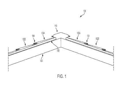
[0029] FIG. 1 is a cross-sectional view of an example roof 100 including
panels 102A, 102B
and couplings 104. The roof 100 includes a support structure 106 and a base
surface 108.
Base surface 108 is coupled to the support structure 106 and can provide a
generally planar
surface which can slope downward from a peak of the roof 110. In some
examples, the base
surface 108 is a planar base surface. The slope (e.g. pitch) of the roof can
be substantially
horizontal, substantially vertical, or any slope therebetween. In some
examples, the slope is a
minimum of 3/12 pitch. In some examples, panels 102A, 102B have a similar
slope as the
base surface, while in some examples, panels 102A, 102B have a different slope
than the base
surface. The roof can have a lower portion and an upper portion with the upper
portion
proximate to the peak of the roof 110 and the lower portion proximate an eave
of a roof In
some examples, base surface 108 can include multiple layers of material. In
some such
examples, base surface 108 can include a first layer of wood (e.g. oriented
strand board)
coupled to a support structure 106 with further layers on top of the first
layer of wood. In
some examples, the layers can include, insulation, tar paper, a vapor barrier,
felt
underlayment, nailing planks, a drip edge, and sheathing. One having skill in
the art will
understand that other layers can be used for base surface 108 and that any
combination of
layers can be used in any order.
CA 03193595 2023- 3- 23
WO 2022/081551
PCT/US2021/054539
[0030] Continuing with the example of FIG. 1, panels 102A, 102B are configured
to cover a
portion of base surface 108. Panels 102A, 102B are secured to each other by
couplings 104
that provide interconnection between at least two panels 102A, 102B. Panels
102A, 102B can
be further secured to the base surface 108 by fasteners (e.g. nails) and/or by
couplings 104.
Panels 102A, 102B and couplings 104 can be made from a rigid material such as
metal,
which can include aluminum, steel, or other alloys, or can be made from other
materials such
as plastics or wood. In some examples, panels 102A, 102B are made from a
combination of
materials. One example advantage of using metal for panels 102A, 102B is that
metal can
provide a more durable roof surface and can better withstand strong winds and
other weather
events, especially when compared to traditional asphalt shingles. In some
examples, panels
102A, 102B can have a textured surface. The textured surface can have many
designs and, in
some examples, can make the panels 102A, 102B appear to resemble traditional
shingles. In
some examples, each of panels 102A, 102B can be made from a single sheet of
rigid material
which can extend laterally across an entire roof, from a first edge to a
second edge. In some
examples, the first edge is a horizontal edge of a roof and the second edge is
the other
horizontal edge of the roof Using a single sheet of material which extends
laterally across the
roof can be advantageous as it can reduce the number of seams between panels.
Reducing the
number of seams can reduce the number of points of ingress for moisture, which
can further
protect the base surface 108 and the rest of a building from water damage.
Additionally,
reducing the number of seams can reduce the number of couplings 104 needed,
which can
allow for easier and faster installation of the panels 102A, 102B.
[0031] In the example of FIG. 1, panels 102A, proximate to the peak of the
roof 110, are
coupled to the peak of the roof 110. In some examples, panels 102A are
directly coupled to
the peak of the roof by fasteners. The peak of roof 110 can be a ridge cap
which, like the
panels, can be made of metal and resist water. In some examples, couplings 104
and the
coupling between the peak of roof 110 and panels 102A, are designed to resist
water from
penetrating the coupling, thereby preventing the exposure of the base surface
108 to water.
This can have the benefit of preventing water from leaking through the roof
100. In some
examples, the peak of the roof can be flat and, in some examples, panels 102A
can be
coupled together to form a peak of the roof
100321 Moving to FIG. 2, FIG. 2 is a cross-sectional view of an example sloped
roof 200
with a first panel 202A and a second panel 202B coupled to a base surface 208
and secured to
each other via coupling 204. In FIG. 2, second panel 202B extends downward
from the first
panel 202A to an cave trim 212 of the roof 200. In FIG. 2, the downward edge
of the second
6
CA 03193595 2023- 3- 23
WO 2022/081551
PCT/US2021/054539
panel 202B can wrap around the eave trim 212. By wrapping the downward edge of
the
second panel 202B around the eave trim 212, moisture can be prevented from
traveling up
under the second panel 202B or any panel located proximate to the eave trim
212. In some
examples, eave trim 212 can include a drip edge. In other examples the eave
trim can have an
integrated drip edge. A drip edge can help prevent water from getting under a
panel. FIG. 2
further includes a gutter 214 supported by a gutter hanger 216 coupled to the
roof 200 via a
fastener 218. The gutter 214 can transport water away from the roof 200 and
from the house
the roof sits atop.
100331 FIG. 2 also includes an underlayment 220 which is located above the
base surface 208
and below the panels 204A, 204B. The underlayment 220 can wrap over the bottom
edge of
the roof to a point on the side of the building as shown by 222. The
underlayment 220 can be
made of a material that is resistant to water and in some examples, resistant
to high
temperatures (e.g. 240 F). In some examples, the underlayment 220 can be self-
adhering to
the base surface 208, with one example being the Englert Metalman HT
underlayment. The
underlayment 220 can be a secondary barrier for preventing water from damaging
the base
surface 208 due to being under the panels and its water resistance.
[0034] Continuing with the example of FIG. 2, coupling 204 includes a
receptacle of the first
panel 204A, an interlock, and a hook portion of the second panel 204B. The
receptacle is
located proximate to the downward edge of the first panel 202A, the hook
portion is located
proximate to the upward edge of the second panel 202B, and the interlock is
located
proximate to the receptacle and the hook portion as is described further
herein. The coupling
204 further includes a sealant located between the receptacle portion and the
hook portion as
described further herein. The sealant can be any water-resistant material
(e.g. butyl) and can
prevent water from entering the coupling 204 between the first panel 204A and
the second
panel 204B. The sealant can be located anywhere within coupling 204 such that
it can prevent
water from entering the coupling. The sealant can be pre-applied or
alternatively the sealant
can be applied at any stage when securing the first panel and the second
panel.
[0035] Moving to FIG. 3A-3C, FIG. 3A-3C enlarged cross-sectional views of
example parts
of the coupling of FIG. 2. In FIG. 3A, a first panel 302A includes a sheet-
like (e.g. planar)
section which has an inner face 324, which faces a base surface, and an outer
face 326,
opposite the inward face, which faces away from the base surface. An end
portion of the first
panel 302A is folded such that the outward face 326 of the first panel 302A
faces toward the
base surface, thereby defining receptacle 328 having an opening proximate to
the inner face.
The receptacle 328 is located at an end of the first panel 302A and is
connected to the sheet-
7
CA 03193595 2023- 3- 23
WO 2022/081551
PCT/US2021/054539
like portion of the first panel 302A which extends away from the receptacle.
The first panel
302A also includes a first end and a second end with an opening defined by the
receptacle
328 facing toward the second end of the first panel 302A. The first panel
further includes a
first projection 330 and a second projection 332. The first projection 330 is
located proximate
to an end of the first panel 302A and extends upward away from the base
surface. The second
projection 332 is located proximate to the end of the first panel 302A and
extends away from
receptacle 328.
[0036] In the example of FIG. 3B, an interlock 334 includes an inner face 336,
which faces a
base surface, and an outer face 338, opposite the inward face 336, which faces
away from the
base surface. An end portion of the interlock 334 is folded such that the
outer face of the
interlock 334 faces toward the base surface, thereby defining a receptacle
340. Receptacle
340, in some examples, can be considered a second receptacle while receptacle
328 can be
considered a first receptacle. The interlock 334 further includes a hook
portion 342 which can
be an interlock hook portion and a receiving portion 344 which can be an
interlock receiving
portion. The interlock hook portion can terminate in an end which in some
examples can be
folded. The interlock receiving portion can form an opening. In some examples,
the interlock
opening and the end of the interlock hook portion face each other.
[0037] In the example of FIG. 3C, a second panel 302B includes a sheet-like
section which
has an inner face 346, which faces a base surface, and an outer face 348,
which faces away
from the base surface. The second panel 302B further includes a folded portion
350 which is
defined by the folding of the second panel into alternating peaks and troughs.
The second
panel 302 further includes a hook portion 352, which can be a second panel
hook portion,
proximate an end of the second panel 302 which extends away from the base
surface. The
sheet-like section of the second panel 302B is connected to and extends away
from the hook
portion 352. The sheet-like section of the second panel 302B can include a
raised section 355
which extends away from the folded portion 350, however in some examples, no
raised
section is included. Folded portion 350 is located proximate hook portion 352.
A sealant 354
is also located proximate to hook portion 352.
[0038] Moving to FIG 4, FIG. 4 is an enlarged, cross-sectional view of an
example installed
coupling 400. Coupling 400 includes first panel 402A, second panel 402B, and
interlock 434.
First panel 402A includes a receptacle 424, a first protrusion 430, and a
second protrusion
432. Line 458 extends from first panel 402A toward second panel 402B and
interlock 434,
defining a receiving area. Second panel 402B includes a folded portion 450, a
hook portion
452, and a sealant 454. Second panel 402B further includes a space 460 above
fastener 462.
8
CA 03193595 2023- 3- 23
WO 2022/081551
PCT/US2021/054539
Interlock 434 includes a receptacle portion 440, a hook portion 442, and a
receiving portion
444. FIG. 4 further includes a base surface 408 and an underlayment 420.
[0039] In an example installed operation, as shown in FIG. 4, first panel 402A
and second
panel 402B are connected to each other. Additionally, first panel 402A is
secured to the base
surface. The second projection 432 of the first panel 402A extends at an angle
toward second
panel 402B and toward base surface 408. The hook portion 452 of the second
panel 402B is
engaged with the second projection 432 of the first panel 402A with the hook
portion 452
being located above the second projection 432 relative to the base surface
408. In this
configuration, the second panel 402B resists downward movement toward an eave
of the roof
and is supported by first panel 402A. Sealant 454, which can be any sealant,
is located
proximate hook portion 452 of second panel 402B and further engages the second
projection
432 of first panel 402A. In some examples, sealant 454 can provide further
support to retain
second panel 402B to first panel 402A. In some examples, sealant 454 can
provide a water-
resistant barrier such that water cannot penetrate between first panel 402A
and second panel
402B. Further, in some examples, folded portion 450 of second panel 402B can
provide a
water-resistant barrier. In some such examples, water, which can flow upward
on the first
panel 402A toward second projection 432 due to capillary action, can adhere to
the folded
portion 450 and be directed away toward the eaves of the roof In some
examples, folded
portion 450 of second panel 402B can be in contact with the first panel 402A.
In the example
of FIG. 4, folded portion 450 can also provide a space 460 between second
panel 402B and
interlock 434. This can be advantageous as the space can prevent fastener 462
from touching
and/or rubbing against second panel 402 which could cause damage to the second
panel 402.
In some examples, second panel 402B can contract and expand with heat and
space 460 can
ensure that little to no wearing occurs between fastener 462 and second panel
402B. Further,
in some examples, folded portion 450 can lift the first panel 402A and can
further support the
first panel 402A such that the receptacle 424 of the first panel 402A is not
in contact with the
base surface 408, thereby providing a lifted section via its peaks. In some
examples, a raised
portion 455 lifts the first panel and can further support the first panel such
that the receptacle
424 of the first panel is not in contact with the base surface, thereby
providing a lifted
section. In some examples, folded portion 450 can lead into raised portion 455
of second
panel 402B while is some examples, the folded portion leads directly to the
sheet-like portion
of the second panel without raised portion 455.
[0040] Continuing with FIG. 4, interlock 434 secures first panel 402A and
second panel
402B to base surface 408 using fastener 462. When installed, the receptacle
portion 440 and
9
CA 03193595 2023- 3- 23
WO 2022/081551
PCT/US2021/054539
hook portion 442 of interlock 434 are situated within the receptacle portion
424 of the first
panel 402A. In some examples, receptacle 440 of interlock 434 is in direct
contact with the
receptacle portion 424 of the first panel 402A such that the first panel 402A
and the interlock
434 are in frictional connection with each other. In the example of FIG. 4,
the first projection
430 protrudes upwards, away from the base surface 408, such that it can
prevent the hook
portion 442 of the interlock from moving toward a peak of the roof, thereby
preventing the
interlock from moving toward the peak of the roof In some examples, the hook
portion 442
can be in contact with the first projection 430 such that the first panel 402A
is prevented from
being pulled downward to the eave of the roof due to interlock 434 being
secured to the base
surface 408 with fastener 462. In some examples, the interlock 434 can be made
of a thicker
and/or stronger material than the first panel 402A such that the interlock can
provide support
to the first panel 402A. Further in the example of FIG. 4, the hook portion
452 of the second
panel 402B is located within the receiving portion 444 of interlock 434. In
this configuration,
the first panel 402A and the second panel 402B cover the interlock 434
completely such that
no part of it is exposed to the exterior of the roof This configuration can be
advantageous as
the connection is hidden from view which can be aesthetically pleasing.
Additionally,
fastener 462 is completely covered by second panel 402B and is not exposed to
water or other
elements which could cause the fastener to rust or otherwise degrade.
Furthermore, this
configuration can be advantageous as water or other possibly damaging elements
can be
prevented from entering the coupling 400 (e.g. through a fastener hole),
thereby protecting
the coupling and the underlying base surface 408.
[0041] Moving to FIG. 5A-5C, FIG. 5A-5C are top-down views of an example
method of
installing a first panel 502A to a second panel 502B with an interlock 536. In
FIG. 5A, a first
panel 502A is provided with interlock 536 being inserted (e.g. slid) into a
side of the first
panel 502A and directed to a different side of the first panel 502A. In some
examples, the
first panel 502A is secured to base surface 508 before interlock 536 is
inserted into a side of
the first panel 502A. However, in some examples, first panel 502A is not
connected to a base
surface before interlock 536 is inserted. It can be advantageous to insert
interlock 536 into
first panel 502A before first panel 502A is secured to the base surface 508 as
it can be
difficult to insert interlock 536 into first panel 502A if first panel 502 is
connected to the base
surface 508. For example, inserting interlock 536 into a first panel 502A
which is already
secured to base surface 508 can require deflection (e.g. bending) of one or
both of first panel
502A and interlock 536. Interlock 536 can include one or more openings 568 in
which one or
more fasteners can be put through to secure interlock 536 to base surface 508.
Moving to
CA 03193595 2023- 3- 23
WO 2022/081551
PCT/US2021/054539
FIG. 5B, multiple interlocks 536 are inserted into first panel 502A. Further,
fasteners 562 are
inserted into openings 568 and fastened to base surface 508 such that
interlock 536 is secured
to base surface 508. Openings 568 can provide a guide for fasteners 562 which
can allow for
quicker and more precise installation. Openings 568 can be any shape including
circles,
ellipses, and rounded rectangles which can allow for various positioning of
fasteners 562
through the openings 568. In some examples, first panel 502A is connected to
base surface
508 prior to fasteners 562 being used to secure interlock 536 to base surface
508. However, in
some examples, interlock 536 is secured to the base surface 508 before first
panel 502A is
secured to the base surface 508. In FIG. 5B, second panel 502B is directed
upward toward
first panel 502A and toward the peak of the roof Moving to FIG. 5C, second
panel 502B is
connected to first panel 502A with interlock 536. One form of connecting
second panel 502B
to first panel 502A is described with reference to FIG. 6A-6D. As indicated by
the dashed
lines in FIG. 5C, interlock 536 is not visible when first panel 502A and
second panel 502B
are connected. This can be advantageous as appearing to have no seams between
panels can
be aesthetically pleasing.
[0042] While two individual interlocks 536 are shown in FIG. 5B, in some
examples, fewer
or more interlocks can be used. In some examples, a single interlock is used
and in some
further examples, the single interlock can stretch across the roof
substantially the same length
as the first and second panels. Various lengths and numbers of interlocks are
contemplated.
[0043] Moving to FIG. 6A-6D, FIG. 6A-6D are perspective views of an example
installation
of a second panel 602B above base surface 608 with a first panel 602A and an
interlock 634
already installed. In the example of FIG. 6A, the interlock 634 is secured to
the base surface
608 by fastener 662. Additionally, FIG. 6A includes an entrance 658 to a
receiving portion
646 of interlock 534. Moving to FIG. 6B, second panel 602B includes a hook
portion 652 at
an end of the second panel 602B. Second panel 602B extends further than shown
in FIG. 6B
as shown by break 666. In installation, second panel 602B can be directed
(e.g. inserted)
toward receiving portion 646 of interlock 634 and beneath first panel 602A. In
FIG. 6C, the
hook portion 652 of the second panel 602B engages the second projection 632 of
first panel
602A and can be deflected (e.g. compressed) by the second projection 632 of
first panel
602A as it passes through entrance 658. In some examples, the second
projection 632 is
deflected (e.g. compressed). However, in some examples, one or both of the
second
projection 632 and the hook portion 652 are not deflected. Second panel 602B
is further
directed upward toward the peak of the roof through entrance 658 and into the
receiving
portion 646 of interlock 634. In FIG. 6D, the hook portion of the 652 of the
second panel
11
CA 03193595 2023- 3- 23
WO 2022/081551
PCT/US2021/054539
602B is uncompressed and connects with the second projection 632 of the first
panel 602A.
Additionally, second projection 632 of first panel 602A is in contact with
sealant 654 of
second panel 602B. Thus, second panel 602B is connected to first panel 602A.
The hook
portion 652 is within the receiving portion 646 of interlock 634. In some
examples, to ensure
proper connection between first panel 602A and second panel 602B, second panel
602B is
directed toward the cave of the roof This can cause second projection 632 to
be further in
contact with sealant 654. As shown in FIG. 6D, folded portions 650 of second
panel 602B
can create a space 660 above fastener 662 which can prevent fastener 662 from
contacting the
bottom of second panel 602B. Further, folded portion 650 of second panel 602B
can lead
directly into a sheet-like portion of the second panel 602B.
[0044] Moving to FIG. 7A-7E, FIG. 7A-7E are perspective views of an example
installation
of an interlock 734 to a first panel 702A above a base surface 708. Starting
with FIG. 7A, a
first panel 710A includes a receptacle portion 724 and a second projection
732. First panel
702A extends further than what is shown by FIG. 7A and the extension is shown
by break
764. In some examples, first panel 702A is secured to the base surface 708
prior to
installation of interlock 734 upward of break 764. However, in some examples,
first panel
702A is not secured to the base surface prior to installation of interlock
734. Interlock 734
includes a receptacle portion 740 and a hook portion 742. In FIG. 7A,
interlock 734 is
directed (e.g. inserted) beneath first panel 702A and forward toward a peak of
the roof In
FIG. 7B, interlock 734 is partially beneath first panel 702A and is passing
through entrance
758. As interlock 734 passes beneath first panel 702A, the interlock 734 and
the first panel
702A can engage with each other. During the engagement, in some examples, the
receptacle
portion 740 and/or hook portion 742 of the interlock 734 can be deflected
(e.g. compressed)
by first panel 702A. Additionally or alternatively, the receptacle 724 of the
first panel 702A
can be deflected (e.g. compressed) by interlock 734. In some examples, the end
of panel
702A which includes the receptacle portion 724 and second projection 732 lifts
upward away
from base surface 708 such that interlock 734 can be passed underneath the
first panel 702A.
In some such examples, compression of interlock 734 can be minimized. Moving
to FIG. 7C,
interlock 734 is beneath first panel 702A and is directed downward toward an
cave of the
roof so interlock 734 can fully interlock with first panel 702A. Specifically,
interlock 734 is
directed such that hook portion 742 is directed into receptacle portion 724 of
the first panel.
In FIG. 7D, the receptacle 724 of first panel 702A is expanded as the
interlock 234 is moved
past first projection 730 of the first panel 702A. Interlock 734 is further
directed downward
(e.g. toward the cave of the roof) until it reaches the position of FIG. 7E.
In FIG. 7E, the hook
12
CA 03193595 2023- 3- 23
WO 2022/081551
PCT/US2021/054539
portion 742 of interlock 734 is in an uncompressed state and receptacle 724 is
also in an
uncompressed state. In this configuration, receptacle 740 and hook portion 742
of the
interlock 734 are located within receptacle 724 of the first panel 702A.
Further, hook portion
742 of the interlock 734 is prevented from moving the interlock substantially
upward toward
the peak of the roof by the first projection 730 of the first panel 702A.
Thus, interlock 734 is
connected with first panel 702A such that they are not easily separated from
each other.
[0045] The example steps of installing panels on a roof as provided in FIG. 5A-
5E, FIG. 6A-
6D, and FIG. 7A-7C can be repeated with additional panels. In some examples,
the steps of
installing are repeated in succession for any additional panels. In some
examples, a user can
secure a first panel to a base surface at a first point using an inserted
interlock. Subsequently,
the user can secure a second panel to the first panel and secure the second
panel to the base
surface using an interlock at a second point. In some examples, the second
point is below the
first point, toward the eaves of a structure. In some examples, the First
point, and thus the First
panel, is located closer to the upper portion of the roof In some examples,
after securing a
second panel to the first panel and the base surface, a third panel can be
secured to the second
panel using a second interlock at a third point below the first and second
points. In such
examples, a user can install panels for a roof in a top-down manner; from a
peak of a
structure to the eaves of the structure. One advantage of installing panels in
a top-down
manner is that a user can avoid contacting a panel that was previously secured
to the base
surface. By not contacting the already installed panels, possible damage from
said contact can
be avoided. For example, a user can avoid stepping on and scratching and/or
bending the
panels. An additional and/or alternative advantage by installing the panels in
a top-down
manner is that the installation can take less time than it would take to
install the panels in a
bottom-to-top fashion. Furthermore, installation can be less complicated than
traditional
installation of panel roofing as a user only needs to push the second panel
under the first
panel and above the interlock to secure the second panel to the first panel.
[0046] In some examples, a portion of a roofing panel can hang over an edge of
the base
surface which can be undesirable. In these examples, a user can remove a
portion of the panel
which hangs over the edge of the base structure. The remaining portion of the
panel can then
be bent over the edge of the base surface to aid in protecting the base
surface from moisture
ingress.
[0047] In the various examples described, the first panel and the second panel
can contain
substantially the same structural design and can be interchangeable. For
example, the first
panel can be swapped with the second panel such that the first panel becomes
the second
13
CA 03193595 2023- 3- 23
WO 2022/081551
PCT/US2021/054539
panel and the second panel becomes the first panel. Further panels can be
similarly attached
to the first panel and the second panel as well as to the base surface. In
some examples, the
first and second panels as well as the further panels can cover an entire
structure, thereby
creating a roof which can protect an underlying structure from weather and in
particular,
ingress of water.
[0048] Various examples have been described. These and other examples are
within the
scope of the following numbered embodiments.
14
CA 03193595 2023- 3- 23