Note: Descriptions are shown in the official language in which they were submitted.
WO 2022/076024
PCT/US2021/016784
PANEL ASSEMBLY WITH MOLDED FOAM BACKING
CROSS-REFERENCE TO RELATED APPLICATIONS
[0001] This application claims priority to and all the benefits of United
States Provisional
Application No. 62/910,705, filed on October 4, 2019 and is also a
continuation-in-part of
International Application No. PCT/US2019/035244, filed June 3, 2019, which
claims priority
to United States Provisional Application No. 62/679,053, filed on June 1,
2018, and United
States Provisional Application No. 62/845,928, filed on May 10, 2019, all of
which are hereby
incorporated by reference in their entireties.
BACKGROUND OF THE INVENTION
1. Field of the Invention
[0002] The present invention relates to a process for molding cover materials
and the cover
materials formed using this molding process. More particularly, the invention
relates to a
process for forming 3-dimensional cover materials and automotive seat trim
covers formed by
this molding process.
2. Description of Related Art
[0003] Automotive vehicles typically include one or more seat assemblies
having a seat
cushion and a seat back for supporting a passenger above a vehicle floor.
Generally, each of
the seat cushion and seat back comprise a foam pad supported by a frame. A
cover is assembled
with the foam pad to provide a finished surface. Each of the seat cushion and
seat back
generally have one or more contoured surfaces and generally require a
contoured cover. The
contoured cover generally comprises a seating surface portion (referred to
hereafter as a trim
cover panel or trim cover) fastened and/or sewn to one or more side pieces.
[0004] Various processes for forming 3-dimensional automotive seat trim covers
are known in
the art. One commonly known method for forming a contoured trim cover is to
cut pieces of
a cover material into desired shapes and sew the pieces together along edges
to form the
contoured trim cover. This cut-and-sew process can be relatively expensive,
time consuming,
and difficult depending on the desired degree of contour in the trim cover.
Additional material
pieces are needed as the desired amount of contour increases. Further,
additional seams and
CA 03193670 2023- 3- 23
WO 2022/076024
PCT/US2021/016784
sew lines may be needed in the trim cover to obtain a desired style
appearance. There is a
practical limit to the amount of detail and the amount of contour that can be
created with a cut-
and-sew trim cover.
[0005] Other known methods for forming a contoured trim cover include a
variety of molding
processes. Molded seating surfaces are desirable for automotive applications
because molded
seating surfaces have reduced material and labor costs when compared to
traditional cut-and-
sew trim covers. Further, additional styling and deeper contours can be
achieved with molding
processes which would be difficult to obtain with cut-and-sew constructions.
Finally, molded
seating surfaces generally have improved craftmanship and improved
cleanability over cut-
and-sew construction because the molded seating surface has fewer sew seams.
[0006] One known method of molding a trim cover, commonly described as Uni-
TrimTm, is
disclosed in U.S. Patent No. 4,722,760. The Uni-TrimTm method generally
comprises the step
of forming a number of spaced apart recessed grooves on the surface of a foam
pad, placing a
cover material on a lower mold having projections corresponding to the
respective recessed
grooves in the surface of the foam pad, molding the cover material to have the
contour of the
lower mold, applying adhesive to the formed cover material, applying the
grooved foam pad
to the formed cover material, and bonding the formed cover material to the
foam pad. This
known process may produce more manufacturing scrap than traditional cut-and-
sew methods
since misbonded covers cannot be reclaimed or reused. In addition, this
process may require
cover materials with high fiber elongation, which increases the cost of the
cover materials while
also limiting the selection of suitable materials. Further, warranty costs are
higher than other
manufacturing methods since the cover material cannot be removed from the foam
pad, and
thus the entire cover and pad assembly must be replaced when damaged.
[0007] Another known method for assembling a trim cover, referred to as
SureBondTM, is
disclosed in U.S. Patent No. 4,692,199. The SureBondTM method generally
comprises applying
a thermoplastic adhesive film and a cover material to a formed cellular foam
pad and applying
superheated steam to diffuse the adhesive layer and permanently bond the cover
material to the
foam pad. The cover material can be reclaimed when defects occur during the
bonding process.
However, the cellular foam pad is typically not reclaimed. Using steam to
diffuse the adhesive
may result in cover material distortion and alter the shape of the cellular
foam pad. Superheated
steam can distort the nap in a fabric cover material during the bonding
process. When the cover
material and the cellular foam pad are not fully bonded, unbonded adhesive
film can give off
CA 03193670 2023- 3- 23
WO 2022/076024
PCT/US2021/016784
annoying crinkle "sounds" in a finished automotive seat. Warranty costs of
SureBondTM covers
are elevated over other known methods since the entire trim cover and foam pad
must be
replaced if there are any issues with either the cellular foam pad or the
cover material.
[0008] An alternate known method of bonding a trim cover to a foam pad is
disclosed in U.S.
Patent No. 5,231,746 and is commonly referred to as PureFitTM. The PureFitTM
process
generally comprises the steps of sewing a front fabric panel and a back fabric
panel together
with the exterior surfaces of the front and back panels facing one another to
form a bag-like
structure, sliding the bag-like structure onto a tongue-like mold, placing an
air impermeable
barrier film on the interior surface of the front panel and applying a vacuum
to form the front
panel around the tongue-like mold, contacting the front panel with a mold
surface of the tongue-
like mold, forming a body of foam material on the interior surface of the
front panel. and
inverting the bag-like structure such that the foam material is positioned
within the bag-like
structure. This known PureFitTM method has a high tooling cost. Further,
improperly formed
seat back covers cannot be reworked and the entire molded cover/foam assembly
is scrapped.
Also, the molded seat back cover is non-breathable since a barrier film is
required for the
vacuum-form process step. Airflow through the foam is restricted by the
barrier film, which
can cause moisture to build up between the automotive seat and an occupant of
the seat.
[0009] A generally known method of forming a seat upholstery panel, referred
to as Cover
Carving TechnologyTm (CCT), is disclosed in U.S. Patent No. 8,794,708. The CCT
method
generally comprises the steps of spraying a cellular foam on a polypropylene
substrate to form
a coated substrate, attaching the coated substrate to a reverse side of a
textile material in a press
comprising a die and punch, and actuating the press to impart a visible shape
in the foam
bonded with the textile material while the foam is in a viscous state. A
resulting seat upholstery
panel typically has little or no airflow through the panel since the cellular
foam is sprayed onto
a polypropylene sheet.
100101 Another known compression molding process developed by Actex, Inc. is
disclosed in
U.S. Patent No. 4,867,826. The Actex method generally comprises the steps of
applying a
heat-curable urethane adhesive to one surface of a compressible polyurethane
foam layer,
directly contacting the adhesive-bearing surface of the foam layer with a
layer of cover material
to form a bilayer, placing the bilayer on a platen, contacting the cover
material layer of the
bilayer with at least one heated projection of a mold tool at a temperature
from about 300 F to
about 480 F (about 150 C to about 250 C), compressing regions of the foam
layer adjacent the
CA 03193670 2023- 3- 23
WO 2022/076024
PCT/US2021/016784
heated projection, melting and collapsing the compressed regions of the foam
layer using the
heat of the projection for a period from about 30 to about 90 seconds to form
permanent
embossed lines in the bilayer, and removing the projections from the bilayer,
and solidifying
the melted collapsed regions of the foam layer. As generally described, the
laminated foam
article is compression molded against a flat lower surface, i.e., contours are
molded into the
foam layer by heated projections pressing into an upper surface of the foam
layer. While the
relatively high molding temperature of about 300 F to about 480 F allows for a
processing
time of about 30 to about 90 seconds as well as curing the urethane adhesive,
this molding
temperature range limits the choice of suitable fabrics. Also, since the foam
article is
compression-molded while maintaining a generally flat lower surface of the
foam layer
(commonly described as a 2-dimensional molding process), the foam article must
be bent to
take on a desired shape for assembly into an automotive seat which can create
cracking and
wrinkling in the finished seat. Warranty costs of Actex foam articles are
similarly elevated
over other known methods since the entire trim cover and foam layer must be
replaced if there
are any issues with either the foam layer or cover material.
100111 It is desirable, therefore, to form an automotive seat trim cover
having a 3-dimensional
shape with up to about 4 inches of localized contour for the seat surface.
Further, it is desirable
to have a seat trim cover that is releasably attached to a seat foam pad.
Also, it is desirable to
minimize the amount of required bending of the trim cover when it is assembled
to an
automotive seat. In addition, it is desirable to have a seat trim cover with a
smooth, seamless
styling surface with hidden tie downs. It is also desirable to have a pre-
defined selvage
extending around the outer perimeter of the seat trim cover that is free of
foam. Furthermore,
it is also desirable to form seat trim covers with increased contours and/or
detailed shapes to
deliver a styled appearance that is not normally achievable with traditional
cut-and-sew
designs. Additionally, it is desirable to integrate secondary features, such
as electronic sensors
and/or seat heaters, to the seat trim cover as part of the molding process.
Likewise, it is
desirable to mold other types of surface covers for automotive interiors and
household
products. Finally, it is desirable to provide seat trim covers with improved
breathability over
other molded trim technologies and comparable thermal comfort to traditional
cut-and-sew
trim covers.
CA 03193670 2023- 3- 23
WO 2022/076024
PCT/US2021/016784
SUMMARY OF THE INVENTION
[0012] A seat trim cover having a 3-dimensional shape for an automotive
vehicle seat is formed
by pre-cutting a laminate blank into a predefined shape having a predefined
selvage extending
around an outer periphery of the laminate blank, vacuum forming the laminate
blank in a 3-
dimensional mold to form a 3-dimensional laminate blank, and forming a molded
foam backing
on the 3-dimensional shaped laminate blank to form the seat trim cover. The
molded foam
backing has an outer perimeter that is spaced apart from the predefined
selvage such that the
predefined selvage is free of foam.
BRIEF DESCRIPTION OF THE DRAWINGS
[0013] Advantages of the present invention will be readily appreciated as the
same becomes
better understood by reference to the following detailed description when
considered in
connection with the accompanying drawings wherein:
100141 Figure 1 illustrates a front perspective view of a vehicle seat having
a molded seat back
trim cover and a molded seat cushion trim cover according to an embodiment of
the present
invention;
100151 Figure 2 illustrates a rear perspective view of the vehicle seat of
Figure 1 having a
molded back panel trim cover according to an embodiment of the present
invention;
[0016] Figure 3 illustrates an exploded view of the vehicle seat of Figure 1
according to an
embodiment of the present invention;
[0017] Figure 4 illustrates a front view of the molded seat back trim cover of
Figure 1 according
to an embodiment of the present invention;
[0018] Figure 5 illustrates a rear view of the molded back panel trim cover of
Figure 2
according to an embodiment of the present invention;
[0019] Figure 6 illustrates a cross-sectional view of the molded seat back
trim cover of Figure
4 taken along section line 6-6 shown in Figure 4 according to an embodiment of
the present
invention;
CA 03193670 2023- 3- 23
WO 2022/076024
PCT/US2021/016784
[0020] Figure 7 illustrates a cross-sectional view of the molded back panel
trim cover of Figure
taken along section line 7-7 shown in Figure 5 according to an embodiment of
the present
invention;
[0021] Figure 8 illustrates a perspective view of a prior art vehicle seat;
[0022] Figure 9A illustrates a cross-sectional view of a portion of the prior
art trim cover of
Figure 8 taken along section line 9A-9A shown in Figure 8;
[0023] Figure 9B illustrates a cross-sectional view of a portion of the prior
art trim cover of
Figure 8 taken along section line 9B-9B shown in Figure 8;
[0024] Figure 10 illustrates typical seat cover hook fasteners insert-molded
into a prior art base
foam pad;
[0025] Figure 11 illustrates prior art seat cover loop fasteners sewn to a
prior art cut-and-sew
trim cover;
[0026] Figure 12 illustrates a partially disassembled perspective view of a
portion of a prior art
scat having an integrated scat heater;
100271 Figure 13 illustrates an expanded view of a molded trilaminate
construction according
to an embodiment of the present invention;
[0028] Figure 14 illustrates a top view of a cover material blank, a moldable
foam interlayer
blank, and a non-woven scrim backing blank according to an embodiment of the
present
invention;
[0029] Figure 15 illustrates a perspective view of a portion of a trilaminate
assembly [laminate
blank] of the cover material layer, moldable foam interlayer, and the non-
woven scrim backing
layer of Figure 13 according to an embodiment of the present invention;
[0030] Figures 16A and 16B are schematic views of a first embodiment of a
laminate blank
having a heating element according to embodiments of the present invention;
[0031] Figure 16C is a perspective view of a molded seat back trim cover
having an integrated
seat heater according to another embodiment of the present invention;
CA 03193670 2023- 3- 23
WO 2022/076024
PCT/US2021/016784
[0032] Figures 17A and 17B are schematic views of a second embodiment of a
laminate blank
having a heating element according to embodiments of the present invention;
[0033] Figures 17C and 17D are perspective views of a molded seat back trim
cover having an
integrated heater according to another embodiment of the present invention;
[0034] Figure 18 illustrates a perspective view of a lower mold tool surface
and an upper mold
tool surface according to an embodiment of the present invention;
[0035] Figure 19 illustrates a perspective view of the trilaminate assembly of
Figure 15 inserted
between the lower mold tool surface and the upper mold tool surface of Figure
18 according to
an embodiment of the present invention;
[0036] Figure 20 illustrates a perspective view of the trilaminate assembly of
Figure 15 and
the mold tools of Figure 19 after a molding process according to an embodiment
of the present
invention;
[0037] Figures 21A, 21B, and 21C illustrate perspective views of an alternate
molding process
according to another embodiment of the present invention;
100381 Figure 22 illustrates a top view of a base foam pad having hook
fasteners according to
an embodiment of the present invention;
[0039] Figure 23 illustrates a bottom view of a molded seat trim cover with
locally attached
loop fasteners according to an embodiment of the present invention;
[0040] Figure 24 illustrates a bottom view a molded seat trim cover according
to an
embodiment of the present invention;
[0041] Figure 25 illustrates a top view of a molded seat trim cover according
to an embodiment
of the present invention;
[0042] Figure 26 illustrates atop view of the molded seat trim cover of Figure
25 after exposure
to environmental aging according to an embodiment of the present invention;
[0043] Figure 27A illustrates a rear view of a molded seat back panel having a
sew seam
between two materials prior to a molding process according to another
embodiment of the
present invention;
CA 03193670 2023- 3- 23
WO 2022/076024
PCT/US2021/016784
[0044] Figure 27B illustrates a partial rear view of the molded seat back
panel of Figure 27A
according to another embodiment of the present invention;
[0045] Figure 28 illustrates a rear view of a molded seat back panel with an
integrated pocket
according to another embodiment of the present invention;
[0046] Figure 29 illustrates a rear view of a molded seat back panel with a
full width pocket
according to another embodiment of the present invention;
[0047] Figures 30A-E illustrate front views of vehicle seats according to
embodiments of the
present invention;
[0048] Figure 31A illustrates a top view of a vehicle seat having molded
buckle pockets
according to another embodiment of the present invention;
[0049] Figures 31B and 31C illustrate partial top views of the molded buckle
pockets of Figure
31A according to another embodiment of the present invention;
[0050] Figure 32 illustrates a view of a molded seat back panel having a
predefined selvage
that is free of foam, according to another embodiment of the present
invention;
100511 Figure 33 shows a view of a pre-cut laminate blank having locating
features, according
to another embodiment of the present invention;
[0052] Figure 34 illustrates a 3-dimensional mold lid and mold base, according
to another
embodiment of the present invention;
[0053] Figure 35 illustrates an enlarged perspective view of a portion of the
mold base of
Figure 34 showing mold locating features and vacuum holes;
[0054] Figure 36 illustrates a perspective view of the pre-cut blank of Figure
33 being inserted
between the mold lid and mold base of Figure 34 such that the locating
features of the laminate
blank are aligned with the mold locating features;
[0055] Figure 37 illustrates a perspective view of the laminate blank of
Figure 33 inserted
within the mold base of Figure 34 with the mold locating features of the mold
base passing
through respective locating features of the laminate blank;
CA 03193670 2023- 3- 23
WO 2022/076024
PCT/US2021/016784
[0056] Figure 38 illustrates a perspective view of the laminate blank of
Figure 33 within the
mold base of Figure 34 after vacuum forming the laminate blank into a 3-
dimensional shape;
[0057] Figure 39 illustrates a cross-sectional view of assembly of the mold
lid and the mold
base of Figure 34 and the laminate blank of Figure 33 after the laminate blank
is vacuum
formed against the mold base and further illustrating liquid components being
injected through
a port in the mold lid into a cavity between the vacuum-formed laminate blank
and the mold
lid;
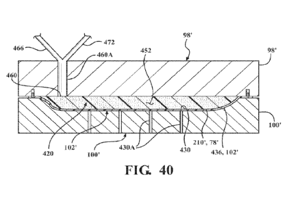
[0058] Figure 40 illustrates a cross-sectional view of the mold lid, the mold
base, and the
vacuum-formed laminate blank of Figure 39, after a molded foam backing is
formed within the
cavity between the vacuum-formed laminate blank and the mold lid;
[0059] Figure 41 shows a perspective view of the molded seat back panel within
the mold base
after forming the molded foam backing on the vacuum-formed laminate blank as
shown in
Figure 40;
[0060] Figure 42 shows a front view of a molded seat back panel illustrating
vacuum formed
surface contours and the pre-defined foam-free selvage, according to another
embodiment of
the present invention;
[0061] Figure 43 shows a rear view of the molded seat back panel of Figure 42,
illustrating the
molded foam backing adhered to the vacuum-formed laminate blank as well as
illustrating the
foam-free predefined selvage extending around the outer periphery of the
molded seat back
panel;
[0062] Figure 44 shows an enlarged view of portion 44 of Figure 43,
illustrating the foam-free
pre-defined selvage;
[0063] Figure 45 shows an enlarged perspective side view of an assembly of the
seat back
panel of Figure 42 with a side facing, illustrating a sew seam joining the
foam-free predefined
selvage of the seat back panel with an edge of the side facing; and
[0064] Figure 46 shows an enlarged perspective top view of the portion of the
trim cover
assembly of Figure 45, illustrating the sew seam being formed within the
predefined foam-free
selvage of the seat back panel.
CA 03193670 2023- 3- 23
WO 2022/076024
PCT/US2021/016784
DETAILED DESCRIPTION OF THE EMBODIMENTS
[0065] Figures 1-7 and 13-46 illustrate molded vehicle seat trim covers and/or
trim
components, vehicle seats having molded trim covers and/or trim components,
and processes
for manufacturing the seat trim covers and/or trim components according to
embodiments
described herein. Directional references employed or shown in the description,
figures or
claims, such as top, bottom, upper, lower, upward, downward, lengthwise,
widthwise, left,
right, and the like, are relative terms employed for ease of description and
are not intended to
limit the scope of the invention in any respect. Further, the Figures are not
necessarily shown
to scale. Referring to the Figures, like numerals indicate like or
corresponding parts throughout
the several views.
[0066] Figures 1 and 2 illustrate perspective views of a vehicle seat assembly
10 having
FreeFormTM molded trim covers 12 according to an embodiment of the present
invention. Trim
covers 12 and other components assembled and compression molded by way of a
process
disclosed herein are optionally described as FreeFormTM components. The
vehicle seat
assembly 10 has a seat back 14 rotatably connected to a seat cushion 16 and a
head restraint 18
coupled with the seat back 14 as is commonly known in the art. The seat
cushion 16 extends
between a front end 2() and an opposite rear end 22 adjacent the seat back 14.
The seat cushion
16 comprises a base foam pad 24 as well as other optional components. The seat
back 14
extends between a top end 26 and an opposite bottom end 28 adjacent the rear
end 22 of the
seat cushion 16. The seat back 14 includes a front surface 30 and a back
surface 32. The seat
back 14 comprises a base foam pad 40 as well as other optional components. As
shown in
Figure 3, each of the seat cushion 16 and the seat back 14 includes a frame
34, 36 for supporting
a molded base foam pad 24, 40. The seat cushion 16 and the front and rear
surfaces 30, 32 of
the seat back 14 are encased in molded trim covers 12 and other optional trim
components.
Each trim cover 12 comprises a molded trim component 45 optionally sewn or
assembled with
one or more side pieces 46 to form a trim cover assembly 48. A seat cushion
trim cover 50 is
assembled with the base foam pad 24 to form the seat cushion 16. A seat back
trim cover 52
and a seat back panel 54 are assembled with the base foam pad 40 to form the
seat back 14 as
shown in Figure 3.
[0067] The present invention relates to molded trim covers for vehicle seats
10. More
specifically, the disclosed molded seat trim covers 12 have an improved
appearance, a
CA 03193670 2023- 3- 23
WO 2022/076024
PCT/US2021/016784
reduction in required sew seams, and improved breathability over traditional
molded trim
covers.
[0068] The FreeFormTM molded seat back trim cover 52 and the FreeFormTM molded
seat back
panel 54 are shown in Figures 4 and 5, respectively, and illustrate molded
features 70, molded
lines 72 having the appearance of sew seams, surface concavity 74, and a 3-
dimensional shape.
Cross-sectional views of the seat back trim cover 52 and the seat back panel
54 are shown in
Figures 6 and 7, respectively. Both the seat back trim cover 52 and the seat
back panel 54
include at least a cover material layer 78 adhered to a moldable foam
interlayer 80. Optionally,
a scrim backing layer 82, typically a woven or non-woven fabric, is adhered to
a lower side 84
of the foam interlayer 80. The cover material layer 78 comprises one or more
of a fabric, vinyl,
and/or leather. Optionally, while not clearly shown in Figure 6, each seat
back trim cover 52
may have additional layers such as adhesives, spacer materials, and/or
functional elements,
such as embedded electronics and/or seat heaters. It will be appreciated that
a variety of
materials can be incorporated into the seat back trim cover 52 prior to
molding as suitable or
desired for an intended application. It will also be appreciated that the
layering construction
options of the seat back trim cover 52 and seat back panel 54 also apply to
the seat cushion
trim cover 50.
[0069] The molded trim covers and back panels 50, 52, 54 optionally have
portions with
sharply curved inclined surfaces 86 and/or gradual tapers 88 in their surface
contours. As
generally shown in Figures 6 and 7, the localized amount and change in slope
in an upper
surface 90 of the trim covers and back panels 50, 52, 54 results in the
appearance of deep
"strong" mold lines 92, shallow "weak" mold lines 94, surface concavity,
and/or localized
curvature providing a 3-dimensional shape. During the molding process
described below, the
trim covers and back panels 50, 52, 54 are molded into a final shape that is
generally retained
after they are removed from mold tools 96 (shown in Figure 18). The 3-
dimensional shape is
primarily created by compression molding the moldable foam interlayer 80
between 3-
dimensional upper and lower mold tools 98, 100 (shown in Figure 18). The mold
tools 96 are
heated to a range of about 150 F to about 320 F to create a temperature
gradient to the foam
interlayer 80. The foam interlayer 80 is moldable in a temperature range of
about 220 F to
about 260 F. The general shape of the trim covers and back panels 50, 52, 54
are maintained
even if they are flexed, i.e., the trim covers and back panels 50, 52, 54
generally return to the
molded shape when they are unrestrained.
CA 03193670 2023- 3- 23
WO 2022/076024
PCT/US2021/016784
[0070] In comparison, commonly known methods of trim cover construction
include known
molded trim technologies and traditional cut-and-sew construction. Figure 8
illustrates a
generally known automotive seat 108 having exemplary trim covers 110, 112 with
generally
known compression molded seams 114 as well as generally known cut-and-sew
seams 116.
The generally known compression molded seams 114, shown in Figures 8 and 9A,
are obtained
by applying a cover material 118 and adhesive (not shown) to a foam layer 120
to form a
cover/foam assembly 122 which is compression molded at high temperatures,
about 300 F to
about 480 F (about 150 C to about 250 C), to form the appearance of seams in
the exemplary
trim cover 110. A partial cross-sectional view of the exemplary seat trim
cover 110 is shown
in Figure 9A illustrating the appearance of the molded seams 114. The
resulting molded seams
114 are typically uniform in appearance with minimal contour in the resulting
upper surface
124 of trim cover 110. Further, the resulting trim cover 110 is typically
stiff and has little or
no breathability. The exemplary known trim cover 110 is generally formed in a
2-dimensional
tool and is bent to take on a desired 3-dimensional shape, which may result in
wrinkles in the
trim cover 110. Finally, the choice of cover materials is limited since the
compression molding
is done at high temperatures in the range of about 300 F to about 480 F.
[0071] A partial cross-sectional view of the exemplary seat trim cover 112 is
shown in Figure
9B illustrating the appearance of cut-and-sew seams 116. The resulting cut-and-
sew seams
116 are typically uniform in appearance with minimal contour in the resulting
upper surface
130 of trim cover 112. Traditional cut-and-sew trim covers 112 require pieces
of material 132,
134 to be cut into shapes and edges 136, 138 of the cut pieces 132, 134 to be
sewn together to
create the overall cut-and-sew trim cover 112, such as illustrated in Figures
8 and 9B. The cut-
and-sew trim cover 112 is expensive since a number of material pieces 132, 134
have to be cut
and sewn together. Further, the cost and complexity, of the cut-and-sew trim
cover 112 is
increased when additional design details are added such as surface contour
and/or seams 116.
[0072] Referring to Figures 10 and 11, a seat trim cover 142 is generally
attached to a base
foam pad 144 using fasteners 146. The base foam pad 144, shown in Figure 10,
includes a
plurality of hook fasteners 148. The seat trim cover 142 has a plurality of
loop fasteners 150
attached to a lower surface 152, 154 of the trim cover 142 as illustrated in
Figure 11. During
assembly, the loop fasteners 150 on the lower surface 154 are aligned with and
connected to
the hook fasteners 148 on the base foam pad 144. Generally, the number of
fasteners 146
required increases as the desired contour of the trim cover 142 increases. One
known method
CA 03193670 2023- 3- 23
WO 2022/076024
PCT/US2021/016784
to minimize fasteners is to permanently adhere the trim cover 142 to the base
foam pad 144.
Another known method is to form the trim cover 142 and foam base pad 144 as
one unit.
However, it is desirable to have a removable trim cover 142 so that the trim
cover 142 can be
replaced if desired.
[0073] Seat heaters 162 are often installed in automotive seat cushions and/or
seat backs. A
partially disassembled view of a typical automotive seat cushion assembly 164
is illustrated in
Figure 12. The typical seat cushion assembly 164 includes the seat heater 162,
a base cellular
foam pad 168, and a seat trim cover assembly 170. The seat trim cover assembly
170 comprises
a trim cover 172 haying a plurality of cover pieces 174, 176. Adjacent cover
pieces 174, 176
are sewn together along edges 178, 180 of the cover pieces 174, 176 to form
sew seams 182.
The cover pieces 174, 176 comprise a cover material layer 186 and a padding
layer 188. The
seat heater 162 typically lays underneath the trim cover 172 and is adhesively
bonded to the
base foam pad 168. Also illustrated are hook fasteners 192 attached to the
base foam pad 168
and loop fasteners 194 attached to the trim cover 172 for removably attaching
the trim cover
172 to the base foam pad 168.
[0074] Seat heaters 162 are generally evaluated based on the time-to-first
sensation (of heat)
for the seat occupant and the power consumption of the seat heater 162 design.
Most
commonly known seat heaters 162 have a time-to-first sensation of about 30 to
about 60
seconds and a power consumption of about 60 to about 90 watts. Time-to-first
sensation is
generally affected by the thickness of the trim cover 172, the density of the
foams and textiles
in the trim cover 172, and the power density / consumption of the seat heater
162 design.
[0075] Haying a thick, plush seat trim cover 172 is very desirable for
occupant comfort. Initial
softness of the cover material layer 186 provides a positive comfort stimulus
to the occupant.
Initial softness is a function of the trim cover 172 hardness and thickness.
Generally, a seat
design having substantial softness/plushness will generally be quite thick.
Plushness can also
be accomplished through softening of the trim cover 172 materials. Since the
seat heater 162
is adhered to the base foam pad 168 underneath the trim cover 172, thicker
trim covers 172
have poorer heat transfer and a longer time-to-first sensation for the
occupant when compared
to thinner trim covers 172.
[0076] Making the trim cover 172 softer will allow the weight of the occupant
to penetrate
deeper into the seat cushion assembly 164 and get physically closer to the
heating elements
CA 03193670 2023- 3- 23
WO 2022/076024
PCT/US2021/016784
200 of seat heater 162. However, excessively soft trim covers 172 can lead to
wrinkling on the
cover material layer 186 over time and deteriorate the craftsmanship and
appearance of the seat
cushion assembly 164.
[0077] Instead of making the trim cover 172 softer to improve time-to-first
sensation, the
power density of the heating elements 200 of the seat heater 162can be
increased to output
more heat to overcome the thickness of the trim cover 172. However, there are
practical limits
to amount of power consumption a seat heater 162 can safely consume. Typical
seat heaters
162 consume approximately 60 watts of energy, and high-performance seat
heaters 162
consume around 90 watts of energy. It is generally desirable to limit the seat
heater 162 power
consumption to 90 watts or less of energy. Certain automotive seat cushion
assembly 164
requirements restrict the seat heater 162 power usage to 90 watts or less.
[0078] The seat heater 162 can be moved closer to the occupant by making the
trim cover 172
thinner, which improves the seat heater 162 performance. However, thin trim
covers 172 can
be less comfortable and feel less plush than desired by the occupant. Thus,
plushness and
occupant comfort are in direct conflict to seat heater 162 performance and
time-to-first
sensation. A better alternative, which will be described below, is to
integrate the seat heater
162 into the trim cover 12 instead of attaching the seat heater 162 to the
base foam pad 168.
[0079] The disclosed Freef ormTm trim covers 12 and components overcome some
of these
limitations with the known seat covers when manufactured with the following
process. The
FreeFormTM trim covers 12 and the process for forming these trim covers 12,
according to
embodiments of the present disclosure, are described below and illustrated in
Figures 13-21.
[0080] A process for molding FreeFormTM trim covers 12 from preformed laminate
blanks
210, according to embodiments of the present invention, is illustrated in
Figures 13-21.
Generally, this process comprises the steps of 1) assembling a laminate blank
210, 2) placing
the laminate blank 210 in a 3-dimensional compression mold tool 96, 3) molding
the laminate
blank 210, at a mold tool temperature of about 150 F to about 320 F, and at a
mold tool
pressure of about 150 psi to about 250 psi, to form a 3-dimensional shaped
molded trim cover
12, and 4) removing the trim cover 12 from the mold tool 96. It will be
appreciated that the
disclosed process may include more or less processing steps, as well as a
different sequence of
steps, as desired for a specific intended application or manufacturing
process.
CA 03193670 2023- 3- 23
WO 2022/076024
PCT/US2021/016784
[0081] Referring to Figure 13, the laminate blank 210 comprises an assembly of
the cover
material layer 78, a first adhesive layer 214, the moldable foam interlayer
80, a second adhesive
layer 218, and the scrim backing layer 82. The cover material layer 78,
moldable foam
interlayer 80, and the scrim backing layer 82 can be described as a cover
material blank 212, a
foam interlayer blank 216, and a scrim backing blank 220, respectively, when
cut into a desired
blank shape 222 as illustrated in Figure 14.
[0082] Figure 15 shows a perspective view of the assembled laminate blank 210.
Generally,
the description of cover material layer 78 and cover material blank 212 are
used
interchangeably. Likewise, the description of moldable foam interlayer 80 and
scrim backing
layer 82 are described interchangeably as foam interlayer blank 216 and scrim
backing blank
220, respectively. It will be appreciated that the phrases "cover material
layer- 78 and "cover
material blank" 212 may be used interchangeably for purposes of this
disclosure. In a similar
fashion, the phrases -foam interlayer" 80 and -scrim backing layer" 82 may be
used
interchangeably with "foam interlayer blank" 216 and "scrim backing blank"
220, respectively.
Further, it will be appreciated that the cover material blank 212, the
moldable foam interlayer
blank 216, and the scrim backing blank 220 can be precut into a desired blank
shape 222 prior
to assembling into the laminate blank 210. Alternatively, the cover material
layer 212, the
moldable foam interlayer 216, and optionally, the scrim backing layer 220 can
be assembled
and adhered into a laminated assembly prior to cutting the laminate blank 210.
Two or more
layers of the laminate blank 210 can be assembled in sheet form and cut into
the desired blank
shape 222 after pre-bonding or pre-attaching the two or more layers. Gerber
cutting is an
exemplary process to pre-cut the layers into the blank shape 222 and/or cut
the laminate blank
210 shape out of two or more assembled layers.
[0083] It will be appreciated that more or less layers may be included in the
laminate blank
210 as desired for a particular application. Further, it will be appreciated
that additional layers
may be added to the laminate blank 210, such as a seat heater or an additional
foam layer having
a different density, to form a quad-layer laminate or a multi-layer laminate.
Likewise, when
the scrim backing layer 220 is omitted, the laminated blank 210 of the cover
material layer 212
and the moldable foam interlayer 216 can be described as a "bilaminate blank-.
Optionally, a
laminated blank 210 of the cover material layer 212, the foam interlayer 216,
and a scrim
backing layer 220 can be referred to as a "trilaminate blank". The term
"laminate blank" 210
describes two or more materials laminated together and cut into a desired
blank shape 222.
CA 03193670 2023- 3- 23
WO 2022/076024
PCT/US2021/016784
Thus, it will be appreciated that the laminate blank 210 may comprise more or
less layers than
illustrated in Figures 13 and 15.
[0084] Generally, the laminate blank 210 has a 2-dimensional shape, i.e. the
laminate blank
210 is generally flat when resting unconstrained on a flat surface.
Preferably, the laminate
blank 210 shape and size are configured so that minimal or no trimming is
required after
molding the trim cover 12 and prior to assembly with other components. An
upper surface 224
of the cover material layer 212 and a lower surface 226 of the scrim backing
layer 220, as
orientated and assembled into the laminate blank 210, are generally referred
to as "A-surface"
and "B-surface", respectively, of the molded trim cover 12.
[0085] One or more adhesive layers 214, 218 fasten the cover material layer
212 and,
optionally, the scrim backing layer 220 to the moldable foam interlayer 216 as
illustrated in
Figures 13 and 15. The selection of an adhesive and/or adhesive method is
based in part on
the choice of materials for the cover material layer 212 and the scrim backing
layer 220. A
variety of known adhesives, such as thermoplastic adhesives, and one-part or
two-part urethane
adhesives (referred to as "1K" and "2K" adhesives), are suitable for bonding
certain cover
material layers 212 and scrim backing layers 220 to the foam interlayer 216.
The adhesive can
be applied by spraying, or can alternatively be a film or web construction.
Thermoplastic
adhesive can be roll-coated onto one or more surfaces to be bonded.
Thermoplastic adhesive
can be remelted at elevated temperatures to separate the cover material layer
212 from the foam
interlayer 216, and then reassemble the cover material layer 212 to the foam
interlayer 216 to
correct defects at any time in the life cycle of the trim cover 12. Both 1K
and 2K type adhesives
have a delayed curing response and act like thermoplastic adhesive in the
first 4 hours,
permitting rebonding if needed. The 1K and 2K adhesives cure to a permanent
bond within 24
hours. Both 1K and 2K adhesive systems eventually become thermosetting
materials, so the
bond between the layers becomes irreversible.
[0086] As an alternative to adhesive, the cover material layer 212 and/or
scrim backing layer
220 can be bonded to the foam interlayer 216 by flame lamination. Flame
lamination is a
commonly known process to bond one or more layers of material to a foam layer
after passing
the foam layer past a flame to melt the surface of the foam. Flame lamination
produces a
permanent bond between the foam interlayer 216, the cover material layer 212,
and/or the scrim
backing layer 220. One or more of the adhesive layers 214, 218 may be
optionally replaced by
flame lamination. The cover material layer 212, the moldable foam interlayer
216, the optional
CA 03193670 2023- 3- 23
WO 2022/076024
PCT/US2021/016784
scrim backing layer 220, and/or other material layers, as desired, may be
adhered to one another
with flame lamination such that one or more adhesive layers 214, 218 are
omitted between the
respective layers 212, 216, 220.
[0087] Additionally, two or more layers 212, 216, 220 may be adhered by flame
lamination
prior to or after adhering one or more additional layers 212, 216, 220 with
adhesive if desired.
It will be appreciated that the selection of adhesive type (such as 1K or 2K
urethane adhesives)
and/or flame lamination is based in part on the selected cover material layer
212 and the desired
processing methods. As is generally well known to those skilled in the art,
certain materials
are suitable for being adhered using flame lamination. Other materials may be
more suitably
bonded with a 1K or 2K urethane adhesive or other known adhesive. For example,
certain
leathers may be unsuitable for being adhered to the moldable foam interlayer
216 using flame
lamination.
100881 Further, additional adhesive layers may be used when the laminate blank
210 includes
more than three layers. Also, individual layers may be adhered to an adjoining
layer prior to
or after cutting the layers into the blank shape 222. For example, the scrim
backing layer 220
and the foam interlayer 216 may be bonded together using flame lamination or
adhesive and
then cut into a foam/scrim blank (not shown). The foam/scrim blank may be
adhered to a pre-
cut cover material blank 212 using an adhesive or flame lamination. It will be
understood that
any combination of adhesive, flame lamination, pre-cutting, and post-cutting,
as well as
material selection and number of layers, may be selected based on the desired
finished trim
cover 12 for a given application and/or preferred manufacturing method.
[0089] Suitable cover material layers 212 include a variety of textiles,
vinyls, and leathers.
Exemplary textiles include polyester, polyester blends, acrylic blends, rayon,
nylon, and similar
fabrics. The selection of a textile for a desired application depends on the
amount of elongation
in the lengthwise and the crosswise direction of the textile in conjunction
with the amount of
forming required during the molding process. Generally, cover material layers
212 having
about 10% to about 25% elongation in both the lengthwise and crosswise
directions have been
found to be desirable. However, cover material layers 212 with more or less
elongation may
be suitable depending on the desired 3-dimensional molded shape and the amount
of concavity
in the mold tools. Fabrics can have a flat surface, a knap construction,
and/or be woven or non-
woven, depending on the desired appearance of the molded trim cover 12.
Optionally, fabrics
CA 03193670 2023- 3- 23
WO 2022/076024
PCT/US2021/016784
can be laminated with foam materials or spacer fabric constructions to
generate a desired
appearance of the molded trim cover 12.
[0090] A wide selection of cover material layers 212 are suitable for use with
the disclosed
molding process since the mold tool 96 temperature range, about 150 F to about
320 F, is
below the distortion temperatures for a variety of fabrics. Molding the trim
cover 12 by
applying heat in a temperature range of about 150 F to about 320 F allows for
an expanded
selection of cover material layers 212, including a variety of fabrics,
vinyls, and leathers.
Certain fabrics are unsuitable for use in known prior art molding processes
having molding
temperatures in a range of about 300 F to about 480 F since these fabrics may
get distorted or
damaged by the higher level of heat. Lowering the mold tool 96 temperature to
a range of
about 150 F to about 320 F reduces and/or prevents fabric distortion during
the molding
process. Further, the lower molding temperatures used in the disclosed process
allows for an
increase in obtainable contour of the 3-dimensional shape of the molded trim
cover 12 without
distorting or damaging the cover material layer 212. Additional materials
and/or laminate
layers can be molded into a 3-dimensional shape by optionally adding vacuum
assist and a
removable barrier film to the molding process, as will be described below.
100911 As shown in Figures 14 and 15, the moldable foam interlayer 216
underneath the cover
material layer 212 is used to achieve the desired final molded shape and to
provide a soft and
comfortable feel in the molded trim cover 12. The firmness, density, and
thickness of the
moldable foam interlayer 216 are selected to achieve a desired look or feel of
the vehicle scat
assembly 10. The moldable foam interlayer 216 is an open cell polyurethane
(PU) foam
formulated to be moldable at temperatures between about 220 F to about 260 F
as desired for
an intended application.
[0092] As is generally known in the art of manufacturing polyurethane foams,
the glass
transition temperature (Tg) of polyurethane foam is related to the upper limit
of service
temperature of the PU foam as well as the temperature at which the PU foam can
be molded.
Further, it is well known in the art that the Tg of a PU foam is affected by
the foam chemistry,
and in particular, the amount of cross-linking in the PU foam. Adding a graft
polyol as well as
adjusting diol content is one method of adjusting the Tg of PU foam. The Tg of
PU foam can
be controlled such that a selected moldable PU foam can be molded at
temperatures between
220 F to about 260 F and still maintain support for the occupant and pass all
applicable testing
requirements, including life cycle, durability, and heat-aging.
CA 03193670 2023- 3- 23
WO 2022/076024
PCT/US2021/016784
[0093] Typical PU foam formulations used in vehicle seating applications are
generally
moldable at temperatures greater than about 320 F. These foam formulations
have previously
been selected in order to assure that vehicle seat assemblies 10 have
acceptable performance
over the life of a vehicle and to permit short manufacturing cycle times.
However, the PU
foams with higher Tg values are difficult to mold and require expensive and/or
complex
molding methods. Further, the high mold temperatures restrict options for the
cover material
layers 212 because some materials are unsuitable for molding at temperatures
above about
320 F. In addition, some of these known molding processes result in trim
covers 110 having
reduced breathability.
[0094] It has been found that by reducing the Tg in moldable PU foam,
satisfactory results can
be obtained molding trim covers 12 with a foam molding temperature of about
220 F to about
260 F, as disclosed in the present invention. Further, since the foam molding
temperature is
about 260 F or less, the cost and complexity of the mold tools 96 is reduced
and the range of
suitable cover material layers 212 is increased.
[0095] The optional scrim backing blank 220 is illustrated in Figure 14. As
shown, the scrim
backing layer 82 has been pre-cut into the scrim backing blank 220 prior to
assembly into the
laminate blank 210. The scrim backing layer 82 improves the handling of the
molded trim
cover 12 when sewn to other components in an assembled trim cover 12. However,
it will be
appreciated that the scrim backing layer 220 may be omitted if desired.
[0096] While the scrim backing layer 82 may be a woven or non-woven fabric,
the elongation
in the fibers of the scrim backing layer 82 impacts the formability of the
laminate blank 210
during the molding process. Fabrics with greater elongation in the fibers are
preferred over
fabrics with less elongation in the fibers when molding highly-contoured
molded trim covers
12. Further, selecting a cover material layer 78 and scrim backing layer 82
having similar
elongation in the fibers is preferred. Some common non-woven scrim backing
layers 82 have
suitable properties for both elongation and loop attachment behavior. Non-
woven scrim
backing layers 82 are inexpensive and pass typical warranty criteria, assembly
criteria, and
disassembly criteria.
[0097] An embodiment of the present invention is illustrated in Figures 16A-
1611 showing a
laminate blank 252 having a seat heater 254 positioned adjacent an A-surface
cover material
layer 256. Seat heaters 254 are a desired option for automotive seats. Molded
trim covers 12
CA 03193670 2023- 3- 23
WO 2022/076024
PCT/US2021/016784
can have improved comfort over traditional cut-and-sew cover designs. Further,
the seat heater
254 can be placed closer to the occupant when the seat heater 254 is
integrated into the molded
trim cover 12 than when the seat heater 254 is placed beneath the trim cover
12. The seat
heater 254 is included in the laminate blank 252 prior to compression molding
the laminate
blank 252 into the molded trim cover 12.
[0098] A schematic view showing the construction of the laminate blank 252
having the
integrated seat heater 254 is shown in Figures 16A. The laminate blank 252 is
assembled by
adhering an upper surface 258 of the seat heater 254 to a lower side 260 of
the A-surface cover
material layer 256. Adhesive layer 264 can be applied to one or both of the
upper surface 258
of the seat heater 254 and/or the lower surface 260 of the A-surface cover
material layer 256
as full surface coverage or applied in local areas as desired for a specific
application. A lower
surface 266 of the seat heater 254 is adhered to an upper surface 268 of a
moldable foam
interlayer 270 by applying an adhesive layer 272 to one or both of the lower
surface 266 of the
seat heater 254 and/or the upper surface 268 of the moldable foam interlayer
270 with local
application or full coverage of adhesive as desired. A non-woven scrim backing
layer 274 is
adhered to a lower surface 276 of the moldable foam interlayer 270 using
adhesive layer 278.
Figure 16B illustrates a schematic view of the laminate blank 252 with the
integrated seat heater
254 after the layers shown in Figure 16A are adhered together.
[0099] It will be appreciated that the individual layers shown in Figure 16A
can be assembled
in any order suitable for an intended application and desired manufacturing
process. Further,
it will be appreciated that any suitable adhesive may be selected based on the
desired
manufacturing process and composition of the A-surface cover material layer
256. In addition,
it will be appreciated that adhesive layer 278 can be replaced with flame
lamination as is
generally known in the art. For example, the non-woven scrim backing layer 274
may be
adhered to the moldable foam interlayer 270 using adhesive or using flame
lamination.
Optionally, the non-woven scrim backing layer 274 can be prebonded to the
moldable foam
interlayer 270 via adhesive or flame lamination, optionally cut into the
desired blank shape 222
before or after bonding, and supplied as a subassembly S to be adhered with
the seat heater 254
and A-surface cover material layer 256. Thus, the laminate blank 252 can be
assembled from
one or more precut blanks (A-surface cover material layer 256, seat heater
254, moldable foam
interlayer 270, scrim backing layer 274, etc.) and/or assembled from precut
blanks comprising
a single layer or subassemblies of at least two layers, and/or assembled as a
laminate assembly
CA 03193670 2023- 3- 23
WO 2022/076024
PCT/US2021/016784
and cut into the final laminate blank shape after the layers are bonded
together. It will also be
appreciated that additional layers can be incorporated into the laminate blank
252 and that
certain layers, such as the scrim backing layer 274, may be optionally omitted
as desired.
[00100]
Adhering the seat heater 254 directly to the lower side 260 of the A-
surface
cover material layer 256 helps minimize the time-to-first sensation for a seat
occupant.
However, there is a risk of the seat heater 254 reading through certain A-
surface cover material
layers 256 as shown in Figure 16C. Figure 16C shows a molded seat back trim
cover 280
having the integrated seat heater 254 adhered to the lower side 260 of the A-
surface cover
material layer 256 after compression molding the laminate blank 252 shown in
Figure 16B.
Seat heater electrical wires 282 extend from an edge 283 of the molded seat
back trim cover
280. The seat heater 254 may slightly read though the A-surface cover material
layer 256 as
indicated by 284 in Figure 16C. For some thin A-surface cover material layers
256, the shape
and texture of the seat heater 254 may be visibly evident and/or the seat
heater 254 may reduce
comfort for the occupant. However, the design and construction of the trim
cover 12 can be
adjusted to minimize the visual impression of the seat heater 254. For
example, placement of
molded lines 72 and molded surface concavity 74 can render the read through of
the seat heater
254 imperceptible to the occupant.
[00101]
An alternate embodiment of a laminate blank 286 construction incorporating
a
seat heater 254 is shown in Figures 17A and 17B that reduces the visible
appearance of the seat
heater 254 on the surface of the molded trim cover 12. Figures 17A and 17B
illustrate
schematic views of layers before they are assembled into the laminate blank
286 and after they
are adhered into a laminate blank 286, respectively. The construction of the
laminate blank
286 is similar to the embodiment shown in Figures 16A and 16B with an
additional layer of
foam lining 288 prelaminated to the lower side 260 of the A-surface cover
material layer 256.
The prelaminated foam lining 288 can be adhered to the A-surface cover
material layer 256
using adhesive or flame lamination as desired and as suitable for the choice
of A-surface cover
material layer 256. Furthermore, the moldable foam interlayer 270 may be
adhered to the
optional scrim backing layer 274 prior to assembling the laminate blank 286.
The prelaminated
foam interlayer/scrim backing layers 270, 274 and the prelaminated A-surface
cover material
layer/foam lining 256, 288 are adhesively bonded to a respective side of the
seat heater 254 as
illustrated in Figures 17A and 17B. A molded seat back trim cover 289 with an
integrated seat
heater 254 is shown in Figures 17C and 17D. The foam lining 288 prelaminated
to the A-
CA 03193670 2023- 3- 23
WO 2022/076024
PCT/US2021/016784
surface cover material layer 256 reduces and/or eliminates the read through of
the seat heater
254 through the A-surface cover material layer 256 as illustrated in Figure
17C. Seat heater
electrical wires 282 extend from an edge 290 of the molded seat back trim
cover 289. Figure
17D is atop perspective view of the molded seat back trim cover 289 shown in
Figure 17C and
illustrates the plushness of the trim cover 289 after the compression molding
process. The
inclusion of the foam lining 288 between the seat heater 254 and the A-surface
cover material
layer 256 somewhat increases the apparent plushness of the trim cover 289.
[00102]
As in the prior embodiment shown in Figures 16A and 16B, the selection of
adhesive layer 278 or flame lamination, as well as the desired coverage of
adhesive layers 264,
272 is based on the intended application and preferred manufacturing methods.
Likewise, the
individual layers can be adhered into an assembly prior to cutting the
laminate blank 286 out
of the adhered layers. Alternatively, the individual layers can be precut into
the desired blank
shape 222 prior to assembly. It will be appreciated that any combination and
order of cutting,
assembling, and adhering desired for an intended application can be selected.
For example,
the A-surface cover material layer 256 can be prelaminated to the foam lining
288 using an
adhesive or using flame lamination. Similarly, the moldable foam interlayer
270 can be
prelaminated to the scrim backing layer 274 using an adhesive or using flame
lamination.
[00103]
Further, it will be appreciated that more or less layers can be
incorporated into
the laminate blank 286 than shown in the Figures. It will be appreciated that
one or more
sensors, electrical circuits, and/or alternate materials such as fiber batting
in place of and/or in
addition to the foam lining 288 can be incorporated into laminate blank 286 if
desired. Also,
while not specifically shown in the Figures, the A-surface cover material
layer 256 can
comprise one or more pieces of material fastened together along a seam and/or
layered together
if desired. For example, a pocket can be pre-sewn to the A-surface cover
material layer 256
and/or two or more materials sewn together along seams to create a desired
style, as will be
further described below with respect to Figures 27A-30E.
[00104]
A tool for molding trim covers 12 from preformed laminate blanks 210,
according to one embodiment of the present invention, is illustrated in
Figures 18-20.
Generally, the molding process comprises the steps of 1) assembling a laminate
blank 210, 2)
placing the laminate blank 210 in a 3-dimensional compression mold tool 96, 3)
molding the
laminate blank 210, at a mold tool temperature of about 150 F to about 320 F,
and at a mold
tool pressure of about 150 psi to about 250 psi, to form a 3-dimensional
shaped molded trim
CA 03193670 2023- 3- 23
WO 2022/076024
PCT/US2021/016784
cover 12, and 4) removing the trim cover 12 from the mold tool 96. It will be
appreciated that
the disclosed process may include more or less processing steps, as well as a
different sequence
of steps, as desired for a specific intended application or manufacturing
process.
[00105]
Exemplary upper and lower mold tools 98, 100 are shown in Figure 18. The
upper and lower mold tools 98, 100 have molding surfaces 300, 302 with a 3-
dimensional
shape, optionally one or more protrusions 304, and optionally one or more
recessed areas 306.
The upper and lower mold tools 98, 100 can have different surface temperatures
to be more
compatible with various constructions of the cover material layer 212 and foam
interlayer 216.
The 3-dimensional shape is formed in a trim cover 12 by placing a laminate
blank 210 between
the upper 3-dimensionally shaped mold tool 98 and the lower 3-dimensionally
shaped mold
tool 100, as generally illustrated in Figure 19, compressing the laminate
blank 210 between the
upper and lower mold tools 98, 100 with about 150 psi to about 250 psi, and
applying heat in
a temperature range of about 150 F to about 320 F to shape and compress the
moldable foam
interlayer 216, and removing the upper mold tool 98 from the molded trim cover
12 (illustrated
in Figure 20) after a processing time of about 90 seconds to about 10 minutes.
The amount of
localized compression, as well as the formed induced surface inclination,
results in a formed
3-dimensional trim cover 12 after molding which generally retains the desired
3-dimensional
shape.
[00106]
It will be appreciated that the compression molding process may
incorporate
vacuum assist as desired for certain selected materials, thickness of the
laminate blank 210, as
well as the degree of contour in the upper and lower molding surfaces 300,
302. While not
shown in the Figures, integrating vacuum assist as well as overall heating
and/or spot heating
into the upper and lower mold tools 98, 100 is generally known to one skilled
in the art of
fabricating molding tools.
[00107]
As illustrated in Figures 21A, 21B, and 21C, an alternate embodiment of
the
disclosed process includes a step of vacuum-form assist prior to a compression
molding step.
Alternatively, the vacuum-form assist step can be performed during the
compression molding
step if desired. Improved appearance, increased 3-dimensional depth, and
improved molded
details can be obtained with certain materials, such a leather and/or thicker
materials or
laminate blanks 210 with more than three layers, by adding vacuum assist
during the molding
process to partially or completely pre-form the laminate blank 210 against the
lower molding
surface 100.
CA 03193670 2023- 3- 23
WO 2022/076024
PCT/US2021/016784
[00108]
Referring to Figure 21A, a laminate blank 210 is placed (arrow 311) on the
lower molding tool 100 and a barrier film 312 is placed (arrow 313) on top of
the laminate
blank 210. Vacuum 314 is applied through the lower mold tool 100 to partially
or fully form
the laminate blank 210 to the lower mold tool 100 as illustrated in Figure
21B. The upper
molding tool 98 is compressed 316 against the barrier film 312 and the
laminate blank 210
while the upper and/or lower molding tools 98, 100 are heated to a temperature
of about 150 F
to about 320 F to shape and compress the moldable foam interlayer 216. The
molding tools
98, 100 optionally may be uniformly heated or may have localized areas with
increased heat
temperature, as desired for an intended application and laminate blank 210
construction.
[00109]
The upper molding tool 98 is removed from the barrier film 312 and molded
trim cover 12 (arrow 317) as shown in Figure 21C. The barrier film 312 is
removed from the
molded trim cover 12 (arrow 318), and the molded trim cover 12 is removed from
the lower
molding tool 100. Optionally, the barrier film 312 can be removed from the
vacuum-formed
laminate blank 210 prior to the laminate blank 210 being compressed by the
upper mold tool
98 and heated to a temperature of about 150 F to about 320 F. Breathability of
the molded
trim cover 12 is generally retained since the barrier film 312 is only used
during the vacuum
forming process 314 and, optionally, during the compression molding process
316, and
removed from the molded trim cover 12 prior to assembling the molded trim
cover 12 into a
finished assembly. It will be appreciated that the disclosed process may
include more or less
processing steps, as well as a different sequence of steps, as desired for a
specific application
or manufacturing process.
[00110]
The selection of the molding temperature range and the location of zone
heating
in the mold are based, in part, on the selected cover material layer 212, the
number of layers in
the laminate blank 210, the selected mold design, and the amount of concavity
and molding
details being formed in the molded trim cover 12. Generally, utilizing a mold
temperature
range of about 150 F to about 320 F is desired. This will allow the foam
interlayer 216 to
mold at a temperature range of about 220 F to about 260 F, producing
acceptable molded trim
covers 12 with machine cycle times from about 90 seconds to about 10 minutes
depending on
the forming aggressiveness and thickness of the laminate blank 210.
[00111]
Compression molding pressures of about 150 psi to about 250 psi are
generally
sufficient to produce satisfactory results. It will be appreciated that more
or less molding
pressure may be desired depending on a specific application, laminate blank
210 construction,
CA 03193670 2023- 3- 23
WO 2022/076024
PCT/US2021/016784
machine configuration, and other factors such as machine cycle time. A
pneumatic cylinder
press is generally adequate to provide the desired amount of compression force
during the
molding process. Aluminum molding tools are generally suitable for the
disclosed molding
process since the desired molding temperature range is generally equal or less
than about 320 F
and the molding pressures are generally equal or less than about 250 psi. The
disclosed
molding process does not require steel molding tools and/or hydraulic presses,
and thus, the
disclosed molding process can use lower cost molding tools and lower cost
machines than
previously known molding methods for trim covers 12. Further, the molding
tools 98, 100 can
have self-contained heating systems (not shown) and can be adapted to have
zonal heating as
needed to facilitate more or less aggressive contours and styling lines.
Vacuum assist can be
integrated in the molding tools when desired for a particular application
and/or laminate blank
210 construction.
[00112]
Since the tooling requirements, as well as the manufacturing process
requirements, are generally moderate (aluminum tools with self-contained
heating in a
temperature range of about 150 F to about 320 F, compression pressures of
about 150 psi to
about 250 psi, and cycle times from about 90 seconds to about 10 minutes), an
exemplary
manufacturing process can comprise about 3 compression molding machines with a
single
operator loading and unloading these molding machines. By assembling and
cutting the
laminate blank 210 prior to the molding process, the operator can load the
laminate blank 210
into each molding machine and remove the molded trim covers 12 after the
molding process is
completed. It is desirable to cut the laminate blanks 210 into a size and
shape prior to molding
such that the molded trim covers 12 require minimal and/or no trimming prior
to assembly into
final trim cover assemblies. By pre-bonding or pre-attaching the laminate
blank 210 layers,
the operator loads the laminate blank 210 into the compression molding machine
instead of
having to load multiple pieces.
[00113]
However, it will be appreciated that more than one blank 210 can be loaded
onto
the lower molding tool 100 prior to initiating the compression molding process
if desired for a
particular application. One example process generally comprises the steps of:
1) placing a
cover material blank 212 and a barrier film 312 onto the lower molding tool
100, 2) vacuum
forming the cover material blank 212 to generally contour around the lower
mold tool 100, 3)
removing the barrier film 312 and placing a seat heater 254 on the pre-formed
cover material
blank 212, 4) placing a foam interlayer blank 216 on top of the seat heater
254, 5) compression
CA 03193670 2023- 3- 23
WO 2022/076024
PCT/US2021/016784
molding the cover material blank 212, the seat heater 254, and foam interlayer
blank 216 to
form a molded trim cover 12, and 6) removing the molded trim cover 12 from the
molding
tools 96. Another example process generally comprises the steps of: 1) loading
a laminate
blank 210 onto the lower molding tool 100, 2) placing a pre-sewn pocket blank
on top of the
laminate blank 210, 3) compression molding the laminate blank 210 and the
pocket blank to
form a trim cover 12 having a pocket, and 4) removing the trim cover 12 having
a pocket from
the compression molding tools 96.
[00114]
Compared to known trim covers 110 molded in 2-dimensional shapes, minimal
bending of the trim cover 12 is required when assembling the trim cover 12
into a trim cover
assembly 48 and when applying the trim cover assembly 48 to a vehicle seat 10.
A reduction
in the necessary bending or folding of the 3-dimensional molded trim cover 12
reduces the
wrinkling induced compared to a 2-dimensional molded trim cover 110. While
less bending
of the trim cover 12 is required when the trim cover 12 is assembled to a
vehicle seat 10, the
trim cover 12 can be bent and twisted during assembly with additional seat
cover components
without permanently distorting the molded trim cover 12. When the trim cover
12 is
unrestrained, the trim cover 12 tends to generally return to the as-molded
shape.
1001151 Edges of the molded trim cover 12 are optionally trimmed and/or skived
prior to
assembling and/or sewing with other seat cover components to form the finished
trim cover
assembly 48.
[00116] The molded trim cover 12 can be permanently or releasably attached to
the base foam
pad 24 to form a padded assembly or during assembly of the vehicle seat 10. A
simplified
"hook & loop" attachment system can be integrated with the molded trim cover
12 and the base
foam pad 24 that cannot be felt by the occupant of the vehicle seat 10. As
shown in Figure 22,
the base foam pad 24 includes hook fasteners 344 of a "hook & loop- attachment
system insert-
molded to an upper surface 346 of the base foam pad 24. As shown in Figure 23,
loop fasteners
348 of a "hook & loop- attachment system are insert-molded to the "B-surface"
of the molded
trim cover 12. Alternatively, the loop fasteners 348 can be assembled with the
lower surface
of the laminate blank prior to the laminate blank 210 being molded into the
trim cover 12 such
that the loop fasteners 348 are permanently adhered to the lower surface of
the trim cover 12
during the compression molding process. Further, the loop fasteners 348 can be
adhered to the
trim cover 12 prior to assembling the trim cover with the base foam pad 24.
The molded trim
cover 12 can be releasably coupled with the base foam pad 24 of the vehicle
seat 10 after the
CA 03193670 2023- 3- 23
WO 2022/076024
PCT/US2021/016784
loop fasteners 348 on the molded trim cover 12 are attached to the hook
fasteners 344 on the
base foam pad 24. Alternatively, some commonly used non-woven scrim backing
layers 82
act as a "loop" fastener 348 of the "hook & loop" attachment system for
attaching the trim
cover 12 to the base foam pad 24, as shown in Figure 24. It will be
appreciated that other
fastening methods may be suitable for an intended application including
directly adhering the
trim cover 12 to the base foam pad 24 with an adhesive. In some applications,
the number and
type of fasteners are reduced over certain known trim covers since the
disclosed molded trim
cover 12 has a 3-dimensional shape and generally retains the molded contours
without
additional fasteners.
[00117] After the trim cover 12 is assembled into a final seat cover assembly
48 (by adding
side components and optional fasteners if needed), the seat cover assembly 48
is placed on the
base foam pad 24 and forms the seat cushion 16 or seat back 14 of the vehicle
seat 10, as
illustrated in Figure 3. The base foam pad 24 provides the main support
surface of a seating
system as well as providing stability to maintain the contours of the overall
seat design. The
base foam pad 24 does not require any design features when desired design
features and styling
lines are formed in molded "A-Surface" trim cover 12. Thus, a standardized
base foam pad 24
can be used with many vehicle seat 10 designs when combined with a variety of
trim cover 12
designs. Using a standardized base foam pad 24 reduces complexity in the foam
manufacturing
plants and seat assembly processes. There is a reduction in scrap and rework
during the
manufacturing process by including the design features in a removable trim
cover 12 in
combination with a simplified base foam pad 24.
[00118] Figures 25 and 26 show a molded trim cover 12 before and after,
respectively,
undergoing GMW 14124 Cycle Q environmental aging. The GMW 14124 Cycle Q, a
General
Motors Worldwide standard test protocol, subjects samples to 176 F temperature
and 75%
humidity over 400 hours to evaluate the trim cover 12 for durability and
suitability for an
automotive interior environment. The trim cover 12 must exhibit no
delamination, no color
distortion, and no un-forming of the foam interlayer 80 during the test. As
illustrated in Figure
26, the trim cover 12 demonstrated no delamination, no color distortion, and
no un-forming of
the foam interlayer 80 after undergoing the GMW 14124 Cycle Q environmental
testing.
[00119] While not shown in the Figures, trim covers 12 were evaluated for
volatile organic
carbon compound (VOC) emission using Ford WSS-M99P2222-F1 test method by
testing a
trim cover 12 at 149 F for 120 minutes and recording key emissions from the
trim cover 12.
CA 03193670 2023- 3- 23
WO 2022/076024
PCT/US2021/016784
A first trim cover 12 with a fabric cover material layer 78 and a first foam
interlayer 80 and a
second trim cover 12 with a vinyl cover material layer 78 with a second foam
interlayer 80
were evaluated. Both test samples had acceptable test results.
[00120] Further, various trim covers 12 were evaluated for breathability by
measuring airflow
rate through the trim cover 12. The breathability of a trim cover 12 is
measured by placing a
sample of the trim cover 12 in a Gurley Densometer and measuring the time to
pass 300 ml of
air through the trim cover 12 per ASTM D-726-58 and AS TM D-202-77 test
methods. Samples
of trim covers, manufactured with the traditional cut-and-sew method, the
PureFitTM method,
the Cover Carving TechnologyTm (CCT), and the disclosed molding process, were
evaluated
for breathability. The airflow rate through the cut-and-sew trim cover sample
was about 150
ml/sec. The airflow through the CCT trim cover sample and the PureFitTM trim
cover sample
were about 15 ml/sec and about 10 ml/sec, respectively. In comparison, the
sample of the trim
cover 12 prepared by the disclosed molding process had an airflow rate of
about 100 ml/sec.
Thus, trim covers 12 prepared by the disclosed molding process allow about 6
to 10 times more
airflow through the trim cover 12when compared to trim covers manufactured
using the CCT
method or the PureFitTM method. While the airflow through the trim covers 12
prepared using
the disclosed molding process is less than the airflow through traditional cut-
and-sew trim
covers, the thermal comfort to an occupant of an assembled vehicle seat 10 is
comparable to
the cut-and-sew trim cover.
[00121] Alternate embodiments of the scat back panel 54 construction arc shown
in Figures
27A- 29. Two or more pieces 350, 352 of cover material 78 can be sewn together
along seams
354 as shown in Figures 27A and 27B if desired. The sewn cover material 78 can
be included
into the laminate blank 210 as the A-surface cover material layer 78. The sew
seams 354 are
encased and molded flush during the molding process. The resulting molded seat
back panel
54 can include additional styling and design details by combining one or more
materials into
the A-surface cover material layer 78 of the laminate blank 210 prior to
molding.
[00122] While not specifically shown in the Figures, some complex seat trim
covers 12 may
be assembled by sewing / adhering one or more preformed sections of the trim
cover 12
together along seams to form more complex shapes of finished trim covers 12.
Further,
secondary processes, such as sewing and/or adhering pockets and other design
details, can be
done after the molding of the trim cover 12. It will be appreciated that cover
materials 78 with
sew seams 354 can be incorporated into the laminate blank 210 for any trim
cover part 12, such
CA 03193670 2023- 3- 23
WO 2022/076024
PCT/US2021/016784
as the seat cushion trim cover 50, seat back trim cover 52, seat back panel
54, and any other
similar trim cover 12.
[00123] Further, as illustrated in Figures 28 and 29, secondary features such
as pockets 356
can be integrated into the laminate blank 210 prior to molding the trim cover
12. Figure 28
shows a pocket 356 sewn into seams 354 of the A-surface cover material layer
78 prior to being
integrated into a laminate blank 210. The sew seams 354 are encased and molded
flush when
the laminate blank 210 is compression molded. A molded seat back panel 54
having a full
overlay pocket 358 is shown in Figure 29. The pocket 358 can be sewn or
adhered to the A-
surface cover material layer 78 prior to being integrated into the laminate
blank 210.
Alternatively, the pocket 358 can be placed on top of the laminate blank 210
after the laminate
blank 210 is placed on the lower molding tool 100 if desired. Further, the
pocket 358 can be
molded into a 3-dimensional shape and then sewn or adhered along the edges to
a molded trim
cover 12. It will be appreciated that the disclosed process may include more
or less processing
steps, as well as a different sequence of steps, as desired for a specific
intended application,
selected materials, and/or desired manufacturing process.
[00124] Figures 30A-30E illustrate non-limiting examples of vehicle seats 10
having a variety
of trim cover 12 designs according to embodiments of the present disclosure.
Seat 10A (Figure
30A) illustrates a single A-surface cover material layer 78 with trim covers
12A having
strongly contoured mold lines 364, subtle mold lines 366 flowing across the
seat cushion 16A,
scat back 14A, and head restraint 18A and fading flush to the local surface at
the end 368 of
the mold lines 366. Seat 10B (Figure 30B) illustrates a seat back trim cover
52B having two
cover materials 350, 352 sewn along seams 354 prior to assembling the laminate
blank 210 and
molding the trim cover 12B. Also shown in Figure 30B are surface embossments
372 formed
in the trim cover 12B during the molding process. Seat 10C demonstrates
stylized
embossments 374 and strong contoured mold lines 364, as well as an integrated
head restraint
18C, as shown in Figure 30C. A variation is illustrated in Figure 30D of two
materials 350,
352 sewn along seams 354 to form the sewn cover material 78 prior to
assembling the laminate
blank 210 and molding the trim cover 12D. Seat 10D also illustrates the first
material 350
having a napped fabric and the second material 352 being perforated leather,
as well illustrating
strong stylized contoured design features 376 and subtle surface contour 378.
[00125] Contours with greater than about 4 inches of concavity can optionally
be formed by
joining smaller molded trim cover sections 382, 384, 386 such as shown in
Figure 30E.
CA 03193670 2023- 3- 23
WO 2022/076024
PCT/US2021/016784
Alternatively, for certain laminate constructions and/or A-surface cover
material layers 78, a
trim cover 12E having substantially greater than about 4 inches of overall
concavity can be
molded using the disclosed process. Generally, up to about 4 inches of
localized concavity is
desired. Sharp bends 390 and gradual changes 392 in surface profile 394 can
increase the
overall concavity well beyond the recommended localized concavity
recommendations. Thus,
depending on the laminate blank 210 construction, the seat back trim cover 52
of seat 10E
shown in Figure 30E can be formed as a single molded seat back trim cover 52
or formed by
joining smaller molded trim cover sections 382, 384, 386 as desired.
[00126] Another embodiment is illustrated in Figures 31A- 31C where portions
of the seat
cushion trim cover 50 include molded seat belt pockets 396, 398. Certain known
vehicle seat
covers have highly contoured sections that are formed by cutting and sewing
multiple small
pieces of material together. One example is seat belt pockets for rear seat
cushions. Typically,
multiple pieces of material are cut and sewn together along seams to form
generally complex
contours required for a seat belt pocket. Cutting and sewing multiple small
pieces is costly and
labor intensive. These multi-piece sewn seat belt pockets can be replaced by
molded seat belt
pockets 396, 398 compression molded from laminate blanks 210 with the
disclosed process.
Seat pocket 396, shown in Figures 31A and 31B, illustrates a molded complex
pocket shape
sewn to a seat cushion trim cover 50. In comparison, seat pocket 398
illustrates a narrow U-
shape pocket with a tight bend at the base 400 of the U-shape (shown in
Figures 31A and 31C).
[00127] It will be appreciated that any combination of materials, fabrics, and
number of pieces
may be used to create the desired styling of trim covers 12 and similar
components. While not
specifically shown in the Figures, the molded trim covers 12 are suitable for
any interior
component of a vehicle, including armrests or door panels. While the above
disclosure is
directed primarily towards vehicle seat trim covers 12, this process can be
used to form any
cover piece for automotive interiors or for household products. Complex shapes
can be molded
from the laminate blank 210, eliminating sewing of multiple pieces to form
complex shapes.
[00128] An alternate embodiment of the seat back panel 54' is shown in Figure
32 illustrating
a predefined selvage 410' that is free of foam extending around an outer
periphery 283' of the
seat back panel 54'. One embodiment of a manufacturing process for forming the
seat back
panel 54' of Figure 32 is illustrated in Figures 33 ¨ 41. Both the seat back
panels 54, 54' include
a molded cover material 78, 78' having molded features 70, 70' and molded
lines 72. 72'.
Further, both embodiments of the seat back panels 54, 54' are produced using a
manufacturing
CA 03193670 2023- 3- 23
WO 2022/076024
PCT/US2021/016784
process wherein a laminate blank 210, 210' is formed to produce the seat back
panel 54, 54', as
illustrated in Figures 18-20 and Figures 34-41.
[00129] In back-of-back applications, such as the seat back panel 54, 54', the
foam interlayer
80, 420 is preferably formed of a relatively dense foam so that the seat back
panel 54, 54' has
a smooth appearance while retaining the desired shape. In the embodiment shown
in Figures
18-20, the foam interlayer 80 is integrated within the laminate blank 210
prior to vacuum
forming and/or compression molding the laminate blank 210. In the embodiment
illustrated in
Figures 34 through 41, the foam interlayer 80 is replaced by a molded foam
backing 420
(shown in Figure 43) that is formed on the laminate blank 210' after the
laminate blank 210' is
vacuum-formed into a 3-dimensional shape. As such, the seat back panel 54' of
Figure 32
illustrates vacuum formed lines and features 72', 70' with additional molded
features 70C, 72B,
70B illustrated in the seat back panel 54" of Figure 43 described below.
Certain formed
features and lines 70', 72' optionally have a curved surface profile, an
embossed appearance,
and/or have the appearance of a sew seam. While a seat back panel 54', 54" is
illustrated,
alternate embodiments include trim covers including seat back trim covers,
seat cushion trim
covers, as well as other trim cover components such as side facings, and the
like.
1001301 The molded seat back panel 54' of Figure 32 includes the predefined
selvage 410'
extending around an outer periphery 283' of the seat back panel 54' that is
free of foam 420. In
contrast, the seat back panel 54 of Figure 5 is formed from a laminate blank
210 having a foam
interlayer 80 extending across the full width and length of the laminate blank
210, as shown in
Figure 15. As illustrated in Figure 5, the foam interlayer 80 is compressed
near the outer edge
283 of the seat back panel 54 during the molding process to provide a
compression molded
selvage 410 extending around the outer periphery 283. The selvage 410, 410'
can be used for
joining the outer periphery 283, 283' of the seat back panel 54, 54 to one or
more other trim
pieces to create a trim cover assembly 416, 416' such as illustrated by the
seat back panel trim
cover assembly 416 shown in Figure 3 and further described below with respect
to Figures 45
and 46. The compression molded selvage 410 that is formed by compression
molding a
relatively dense foam 80, 216 results in a relatively stiff selvage 410 which
is more difficult to
sew through than a foam-free selvage 410' shown in Figure 32. It is desirable
to have a seat
back panel 54, 54' with an improved sewing capability. The foam-free selvage
410', 410" of
the seat back panels 54', 54" shown in Figures 32, 42, and 43 have improved
sewing capability
CA 03193670 2023- 3- 23
WO 2022/076024
PCT/US2021/016784
over the embodiment shown in Figure 5 since the foam-free selvage 410', 410"
is less stiff than
the compression molded selvage 410.
[00131] The foam-free selvage 410', 410" of the seat back panel 54', 54" shown
in Figures 32,
42, and 43 is preferred in some embodiments over the compression molded
selvage 410 of the
seat back panel 54 shown in Figure 5 since the foam-free selvage 410', 410"
has less layers to
be included in the sew seam 418, 418' than with the compression molded selvage
410. Further,
the foam-free selvage 410', 410" is more flexible than the compression molded
selvage 410
since the foam-free selvage 410', 410" lacks the relatively stiff foam 80,
216, 420.
[00132] Referring to Figure 33, the seat back panel 54' is formed from a
laminate blank 210'
comprising at least a cover material 78'. A first surface 210A of the laminate
blank 210' forms
the A-surface 210A of the seat back panel 54', as illustrated in Figure 32. An
opposing second
surface 210B of the laminate blank 210' is shown in Figure 33. The laminate
blank 210' is pre-
cut into a predetermined shape having an outer periphery 283'. A plurality of
locating holes
422 are punched through the laminate blank 210' near the outer periphery 283'.
Any number,
shape, size, and location of pre-punched locating holes 422 can be included in
the laminate
blank 210' as desired for specific embodiments. The locating holes 422 can be
punched before,
during, or after the laminate blank 210' is cut from the cover material 78'.
Preferably, each
locating hole 422 passes through the predefined selvage 410' of the laminate
blank 210'. The
predefined selvage 410' extends between a predefined boundary 410C and the
outer periphery
283' of the laminate blank 210', as shown in Figure 33.
[00133] While a single layer laminate blank 210' is illustrated in Figure 33
comprising a cover
material 78', any number of additional layers can be included within the
laminate blank 210' as
desired for specific embodiments, including but not limited to, one or more
layers of foam,
scrim backing, pre-sewn sections of material forming a single layer within the
laminate blank
210', and partial layers such as pre-sewn pockets, and the like. Further,
other components such
as heating elements, a seat heater, electrical sensors, attachment devices,
fasteners, and the like
can be integrated within the laminate blank 210' and/or assembled with the
laminate blank 210'
during the manufacturing process.
[00134] Preferably, the laminate blank 210' includes the pre-punched locating
holes 422. In
some embodiments, the laminate blank 210' can include alternate locating
features such as
slots, slits, tabs, and the like as non-limiting examples. Further, in some
embodiments, the
CA 03193670 2023- 3- 23
WO 2022/076024
PCT/US2021/016784
locating holes 422 can be omitted if the locating holes 422 are not required
to position the
laminate blank 210' within the molding tools 98', 100'.
[00135] Figure 34 shows one embodiment of molding tools 98', 100' suitable for
forming the
seat back panel 54'. The exemplary molding tools 98', 100' include a mold lid
98' and a mold
base 100'. The mold base 100' includes a 3-dimensional mold bowl 102' having a
desired
molded shape for the seat back panel 54'. An outer periphery 424 of the 3-
dimensional mold
bowl 102' includes a plurality of spaced apart locating pins 426. The number
and position of
the locating pins 426 is selected based in part on the size and shape of the
outer periphery 424
of the 3-dimensional mold bowl 102'.
[00136] An enlarged view of portion 35 of the mold base 100' of Figure 34 is
shown in Figure
35, illustrating the locating pins 426 positioned around the outer periphery
424 of the 3-
dimensional mold bowl 102'. Also shown in Figure 35, the 3-dimensional mold
bowl 102'
includes a plurality of vacuum holes 430 distributed across a lower surface
436 of the mold
bowl 102'. In one embodiment, the vacuum holes 430 have an outer diameter of
about 0.003-,
however, larger and/or smaller diameter vacuum holes 430 can be used if
desired based on
specific requirements of an embodiment.
[00137] As shown in Figure 34, the mold lid 98' includes a plurality of lid
holes 426B
configured to matingly engage with the locating pins 426 around the outer
periphery 424 of the
mold bowl 102'. More specifically, the locating pins 426 and the lid holes
426B are configured
such that an upper end 426A of each locating pin 426 fits within a respective
one of the lid
holes 426B when the mold lid 98' is placed in a closed position in frictional
engagement with
the mold base 100'.
1001381 Figures 36 through 41 illustrate an exemplary manufacturing process
for forming the
seat back panel 54' of Figure 32. Referring to Figure 36, the laminate blank
210' is inserted
between the mold lid 98' and the mold base 100'. More specifically, the
laminate blank 210' is
assembled with the 3-dimensional mold bowl 102' by aligning the locating holes
422 in the
laminate blank 210 with the locating pins 426 extending vertically from the
mold base 100'.
As illustrated in Figure 37, the laminate blank 210' is positioned against the
mold base 100'
such that the locating pins 426 extend through the locating holes 422 in the
laminate blank
210'. Prior to fixedly coupling the mold lid 98' to the mold base 100', an
upper molding surface
440 of the mold lid 98' is preferably coated with a mold release. The upper
molding surface
CA 03193670 2023- 3- 23
WO 2022/076024
PCT/US2021/016784
440 of the mold lid 98' has a 3-dimensional mold surface 440 for forming the B-
surface 488 of
the molded foam backing 420.
[00139] The laminate blank 210' is vacuum formed to conform to the contour of
the 3-
dimensional mold bowl 102', as illustrated in Figure 38. Air is drawn through
the vacuum holes
430 in the lower surface 436 of the 3-dimensional mold bowl 102' during the
vacuum forming
process. The vacuum forming process can be performed before or after placing
the mold lid
98' against the mold base 100'. The locating holes 422 in the laminate blank
210' assembled
with the locating pins 426 retains the outer periphery 283' of the laminate
blank 210' in a
desired position during the vacuum forming process. Molded features 70' and
molded lines 72'
are formed in the laminate blank 210' during the vacuum forming process, as
shown in Figure
38.
[00140] Figure 39 shows a cross-sectional view of the mold lid 98' fixedly
coupled to the mold
base 100'. The vacuum formed laminate blank 210' is positioned against the 3-
dimensional
mold bowl 102' with the outer periphery 283' of the laminate blank 210'
retained by the locating
pills 426 passing through the locating holes 422 in the laminate blank 210'.
The upper end 426A
of each locating pin 426 is inserted within a respective mating lid hole 426B
in the mold lid
98'. The outer periphery 283' of the laminate blank 210' is pinched between
the mold lid 98'
and the mold base 100', forming a seal around the outer periphery 424 of the 3-
dimensional
mold bowl 102'. In other embodiments, the laminate blank 210' can be fully
contained within
the 3-dimensional mold bowl 102' such that the outer periphery 283' of the
laminate blank 210'
is spaced apart from the mold lid 98'. In one embodiment, the mold base 100'
and mold lid 98'
are configured to provide about a 0.5 mm parting line gap to accommodate the
outer periphery
283' of the laminate blank 210'.
[00141] Also shown in Figure 39, each vacuum hole 430 in the 3-dimensional
mold bowl 102'
is fluidically coupled to a respective vacuum air channel 430A. A vacuum
pressure is applied
to the vacuum air channels 430A during the vacuum process to draw the laminate
blank 210'
against the lower surface 436 of the 3-dimensional mold bowl 102'. Vacuum
forming the
laminate blank 210' against the lower surface 436 of the 3-dimensional mold
bowl 102' forms
a cavity 452 between the laminate blank 210' and the mold lid 98', as shown in
Figure 39.
Preferably, the mold base 100' and/or the mold lid 98' are heated to a
temperature between
about 140 F to about 150 F. However, other molding temperatures can be
selected in other
embodiments depending on requirements of specific manufacturing processes.
CA 03193670 2023- 3- 23
WO 2022/076024
PCT/US2021/016784
[00142] Referring to Figures 34 and 39, the mold lid 98' includes an inlet
port 460 for injecting
liquid into the cavity 452. The inlet port 460 is fluidically connected to an
inlet channel 460A
passing through the mold lid 98', as illustrated in Figure 39. The inlet
channel 460A is
fluidically coupled to at least a first fill line 466 and a second fill line
472. The first and second
fill lines 466, 472 are configured to provide a first liquid 466A and a second
liquid 472A,
respectively, into the inlet channel 460A. In other embodiments, the inlet
channel 460A is
fluidically coupled to a plurality of fill lines 466, 472 with each fill line
466, 472 configured to
provide one liquid additive 466A, 472A to the inlet channel 460A. The first
and second liquids
466A, 472A are mixed within the inlet channel 460A to form a mixed liquid 460B
that is
injected through the inlet port 460 and into the cavity 452. The first and
second liquids 466A,
472A, along with potentially other selected components based on the specific
requirements of
a selected seat back panel 54', can comprise in part a blended polyol 466A and
isocyanate (ISO)
472A, as a non-limiting example. The blended polyol 466A and the isocyanate
472A are
injected and/or poured through the first fill line 466 and second fill line
472, respectively, and
into the inlet channel 460A. Mixing and injecting the blended polyol 466A and
isocyanate
472A into the cavity 452 within the mold 98', 100' causes the blended polyol
466A and the
isocyanate 472A to react and form a molded polyurethane foam backing 420
within the cavity
452. The molded foam backing 420 is adhered to the laminate blank 210' during
the reaction
process. The assembly of the molded foam backing 420 and the laminate blank
210' forms the
seat back panel 54' shown in Figure 32. In some embodiments of the seat back
panel 54', the
molded foam backing 420 has a density of about 425 kg/m', a thickness of about
3 mm, and a
cure time of about 2 minutes.
[00143] Referring to Figure 41, once the foam reaction process is complete,
the mold lid 98'
is removed from the mold base 100'. As shown in Figure 41, the outer periphery
283' of the
laminate blank 210' is free of foam. The molded foam backing 420 has an outer
periphery 420A
spaced apart from the outer periphery 283' of the laminate blank 210' to form
the foam-free
selvage 410' extending around the outer periphery 283' of the seat back panel
54'. The
predefined selvage 410' of the laminate blank 210' that forms a gasket between
the mold lid
98' and the mold base 100' is spaced apart from the molded foam backing 420
that is formed
by the reaction of the blended polyol 466A and the isocyanate 472A within the
cavity 452.
After the mold lid 98' is removed from the mold base 100', the seat back panel
54' can be
removed from the 3-dimensional mold bowl 102'. Optionally, the seat back panel
54' is placed
CA 03193670 2023- 3- 23
WO 2022/076024
PCT/US2021/016784
in a cooling fixture after removal from the mold base 100', allowing the
molded foam backing
420 to cool down.
[00144] Figures 42 and 43 show another embodiment of the seat back panel 54"
produced
using the manufacturing process illustrated in Figures 34 through 41. Figures
42 and 43 show
the A-surface 486 and B-surface 488 of the seat back panel 54", respectively.
The A-surface
486 of the seat back panel 54" faces outward from the vehicle seat 10 with the
B-surface 488
facing towards the interior of the vehicle seat 10, as further illustrated in
Figure 3.
[00145] As with the seat back panel 54' shown in Figure 32, the seat back
panel 54" of Figure
42 includes a laminate blank 210" comprising a cover material 78" that forms
the A-surface
486 of the seat back panel 54". In the embodiment shown in Figure 42, the
cover material 78"
comprises a vinyl textile, however, other materials such as fabric and/or
leather can be
substituted for the vinyl textile. In addition, the laminate blank 210"
forming the A-surface 486
of the seat back panel 54" can include a plurality of layers if desired for
specific embodiments,
including but not limited to a pre-sewn pocket layer, a foam interlayer, a
scrim backing layer,
and the like. Further, while the A-surface 486 of the laminate blank 210" is
shown in Figure
42 comprising a single piece of cover material 78", other embodiments of the A-
surface 486 of
the laminate blank 210" can comprise a plurality of pre-sewn pieces 350, 352,
such as
illustrated in Figure 27A, and/or a pre-sewn pocket 356, such as illustrated
in Figure 28.
Alternatively, the laminate blank 210" can include a secondary A-surface 358,
such as a pre-
sewn pocket layer 358 such as illustrated in the scat back panel 54 shown in
Figure 29.
[00146] The A-surface 486 of the seat back panel 54" shown in Figure 42
includes molded
features 70" and molded lines 72" formed during the vacuum forming step
described with
respect to Figure 38. Various embodiments can include any number, contour, and
combination
of molded features 70" and molded lines 72" as desired for specific
applications.
[00147] Further, the width of the foam-free selvage 410', 410" can vary as
required for specific
applications, as illustrated in Figures 32 and 42. For example, in the
embodiment shown in
Figure 32, the seat back panel 54' has a foam-free selvage 410' having a
generally uniform
width of approximately 8 mm extending around the outer periphery 283' of the
seat back panel
54'. In contrast, in the embodiment shown in Figure 42, the seat back panel
54" has a foam-
free selvage 410" comprising sections 410A having a width of about 8 mm as
well as
comprising sections 410B having a width greater than about 8 mm. While a foam-
free selvage
CA 03193670 2023- 3- 23
WO 2022/076024
PCT/US2021/016784
410', 410" having a width of about 8 mm is preferred, the selected width of
the foam-free
selvage 410', 410" can be larger and/or smaller than about 8 mm as desired for
different
embodiments. For example, a wider foam-free selvage 410', 410" may be
desirable depending
in part on a selected manufacturing process, the complexity of the vehicle
seat cover 12 design,
and the like.
[00148] In the embodiment of the seat back panel 54" shown in Figure 43, the
molded foam
backing 420 on the B-surface 488 has an outer periphery 420A that corresponds
to a molded
line 72A on the A-surface 486 shown in Figure 42 Also, the molded foam backing
420 of the
seat back panel 54" shown in Figure 43 includes molded lines 72B and molded
features 70B,
70C that correspond to respective molded lines 72B" and molded features 70B",
70C" visible
on the A-surface 486 shown in Figure 42. Each of the molded features 70C on
the B-surface
488 of the seat back panel 54" includes an aperture 70D that is free of foam.
The laminate blank
210" extends across the apertures 70D. The apertures 70D are optionally
pierced during an
additional manufacturing process, providing a passageway 70D through the seat
back panel
54" for a fastener. Additional molded features 492, 495, such as a foam gate
492 formed by the
inlet port 460 in the mold lid 98' and auto-vent marks 495 formed by venting
channels within
the mold lid 98' are visible on the B-surface 488 of the seat back panel 54".
Features such as
the molded features 70B, 70C, molded lines 72B, molded apertures 70D, foam
gate 492, and
the auto-vent marks 495 will vary in location, size, number, and the like, in
various
embodiments of seat back panels 54', 54" formed using the above manufacturing
process
described in Figures 34 through 41. In some embodiments certain features can
be omitted
entirely.
[00149] An enlarged view of portion 44 of the B-surface 488 of the seat back
panel 54" of
Figure 43 is shown in Figure 44, further illustrating the foam-free selvage
410" extending
between the outer periphery 420A of the molded foam backing 420 and the outer
periphery
283" of the laminate blank 210". The foam-free selvage 410" includes both
generally uniform
narrow sections 410A having an approximate width of about 8 mm and wider
sections 410B.
The specific width of the foam-free selvage 410", including foam-free sections
such as 410B,
is selected based on the requirements of specific embodiments. The foam-free
selvage 410" is
formed by pinching the outer periphery 283" of the laminate blank 210" between
the mold lid
98' and the mold base 100', preventing the adhesion of the molded foam backing
420 in these
CA 03193670 2023- 3- 23
WO 2022/076024
PCT/US2021/016784
areas. Also shown in Figure 44 are locating holes 422 extending around the
outer periphery
283" of the laminate blank 210".
[00150] Figures 45 and 46 illustrate perspective views of a sew seam 418
between the foam-
free selvage 410" of the seat back panel 54" and a side facing 540. In the
embodiment shown
in Figures 45 and 46, the side facing 540 comprises a layered assembly of a
scrim backing layer
540A, a foam interlayer 540B, and a fabric A-surface layer 540C. However, the
side facing
540 can comprise any number of layers 540A, 540B, 540C, including being a
single A-surface
layer 540C. The seat back panel 54" is assembled with the side facing 540 and
other trim pieces
(not shown) to form a seat back panel trim cover assembly 416'. The A-surfaces
486, 540C of
the seat back panel 54" and the side facing 540 are assembled facing one
another with the outer
periphery 283" of the seat back panel 54" aligned with an outer periphery of
the side facing
540. Once the seat back panel 54" is assembled with the side facing 540, a sew
seam 418' is
sewn through the layers of the 540A, 540B, 540C of the side facing 540 and the
foam-free
selvage 410" of the seat back panel 54" to form the seat back panel trim cover
assembly 416'.
The foam-free selvage 410" of the seat back panel 54" minimizes the thickness
of the sew seam
418' since the outer periphery 420A of the molded foam backing 420 is spaced
apart from the
sew seam 418'.
[00151] The disclosed FreeFormTM trim covers and other component manufactured
using the
FreeFormTM processes have many benefits over other known methods of
manufacturing trim
covers. One benefit is the FrecFormTM trim covers have similar breathability
to traditional cut-
and-sew trim covers while eliminating most or all of the sew seams. A second
benefit is the
amount of styling details, contours, and complexity in the trim cover can be
increased over
what is practical with the traditional cut-and-sew covers. A third benefit is
the manufacturing
process has a low tooling cost which further permits quickly updating styling
changes by
replacing the lower cost mold tools. A fourth benefit is the integration of
seat heaters and other
components directly into the trim cover during the preparation of the laminate
blank. A fifth
benefit is a seat trim cover having a seamless styling surface with hidden tie
downs. A sixth
benefit is forming a predefined selvage extending around the outer perimeter
of the seat trim
cover that is free of foam. Another benefit is the FreeFormTM process is
suitable for
manufacturing other contoured covers and similar parts for a variety of
automotive and
household applications.
CA 03193670 2023- 3- 23
WO 2022/076024
PCT/US2021/016784
[00152] The invention has been described in an illustrative manner, and it is
to be understood
that the terminology, which has been used, is intended to be in the nature of
words of
description rather than of limitation. Many modifications and variations of
the present
invention are possible in light of the above teachings. It is, therefore, to
be understood that
within the scope of the appended claims, the invention may be practiced other
than as
specifically described.
CA 03193670 2023- 3- 23